EP3473482B1 - Loading system having an energy module, refuse truck with such a system and implementing method - Google Patents
Loading system having an energy module, refuse truck with such a system and implementing method Download PDFInfo
- Publication number
- EP3473482B1 EP3473482B1 EP18201301.1A EP18201301A EP3473482B1 EP 3473482 B1 EP3473482 B1 EP 3473482B1 EP 18201301 A EP18201301 A EP 18201301A EP 3473482 B1 EP3473482 B1 EP 3473482B1
- Authority
- EP
- European Patent Office
- Prior art keywords
- energy
- loading system
- lifting
- energy module
- bin
- Prior art date
- Legal status (The legal status is an assumption and is not a legal conclusion. Google has not performed a legal analysis and makes no representation as to the accuracy of the status listed.)
- Active
Links
Images
Classifications
-
- B—PERFORMING OPERATIONS; TRANSPORTING
- B60—VEHICLES IN GENERAL
- B60L—PROPULSION OF ELECTRICALLY-PROPELLED VEHICLES; SUPPLYING ELECTRIC POWER FOR AUXILIARY EQUIPMENT OF ELECTRICALLY-PROPELLED VEHICLES; ELECTRODYNAMIC BRAKE SYSTEMS FOR VEHICLES IN GENERAL; MAGNETIC SUSPENSION OR LEVITATION FOR VEHICLES; MONITORING OPERATING VARIABLES OF ELECTRICALLY-PROPELLED VEHICLES; ELECTRIC SAFETY DEVICES FOR ELECTRICALLY-PROPELLED VEHICLES
- B60L1/00—Supplying electric power to auxiliary equipment of vehicles
- B60L1/003—Supplying electric power to auxiliary equipment of vehicles to auxiliary motors, e.g. for pumps, compressors
-
- B—PERFORMING OPERATIONS; TRANSPORTING
- B60—VEHICLES IN GENERAL
- B60L—PROPULSION OF ELECTRICALLY-PROPELLED VEHICLES; SUPPLYING ELECTRIC POWER FOR AUXILIARY EQUIPMENT OF ELECTRICALLY-PROPELLED VEHICLES; ELECTRODYNAMIC BRAKE SYSTEMS FOR VEHICLES IN GENERAL; MAGNETIC SUSPENSION OR LEVITATION FOR VEHICLES; MONITORING OPERATING VARIABLES OF ELECTRICALLY-PROPELLED VEHICLES; ELECTRIC SAFETY DEVICES FOR ELECTRICALLY-PROPELLED VEHICLES
- B60L50/00—Electric propulsion with power supplied within the vehicle
- B60L50/40—Electric propulsion with power supplied within the vehicle using propulsion power supplied by capacitors
-
- B—PERFORMING OPERATIONS; TRANSPORTING
- B60—VEHICLES IN GENERAL
- B60L—PROPULSION OF ELECTRICALLY-PROPELLED VEHICLES; SUPPLYING ELECTRIC POWER FOR AUXILIARY EQUIPMENT OF ELECTRICALLY-PROPELLED VEHICLES; ELECTRODYNAMIC BRAKE SYSTEMS FOR VEHICLES IN GENERAL; MAGNETIC SUSPENSION OR LEVITATION FOR VEHICLES; MONITORING OPERATING VARIABLES OF ELECTRICALLY-PROPELLED VEHICLES; ELECTRIC SAFETY DEVICES FOR ELECTRICALLY-PROPELLED VEHICLES
- B60L50/00—Electric propulsion with power supplied within the vehicle
- B60L50/50—Electric propulsion with power supplied within the vehicle using propulsion power supplied by batteries or fuel cells
-
- B—PERFORMING OPERATIONS; TRANSPORTING
- B60—VEHICLES IN GENERAL
- B60L—PROPULSION OF ELECTRICALLY-PROPELLED VEHICLES; SUPPLYING ELECTRIC POWER FOR AUXILIARY EQUIPMENT OF ELECTRICALLY-PROPELLED VEHICLES; ELECTRODYNAMIC BRAKE SYSTEMS FOR VEHICLES IN GENERAL; MAGNETIC SUSPENSION OR LEVITATION FOR VEHICLES; MONITORING OPERATING VARIABLES OF ELECTRICALLY-PROPELLED VEHICLES; ELECTRIC SAFETY DEVICES FOR ELECTRICALLY-PROPELLED VEHICLES
- B60L7/00—Electrodynamic brake systems for vehicles in general
- B60L7/10—Dynamic electric regenerative braking
-
- B—PERFORMING OPERATIONS; TRANSPORTING
- B65—CONVEYING; PACKING; STORING; HANDLING THIN OR FILAMENTARY MATERIAL
- B65F—GATHERING OR REMOVAL OF DOMESTIC OR LIKE REFUSE
- B65F3/00—Vehicles particularly adapted for collecting refuse
-
- B—PERFORMING OPERATIONS; TRANSPORTING
- B65—CONVEYING; PACKING; STORING; HANDLING THIN OR FILAMENTARY MATERIAL
- B65F—GATHERING OR REMOVAL OF DOMESTIC OR LIKE REFUSE
- B65F3/00—Vehicles particularly adapted for collecting refuse
- B65F3/02—Vehicles particularly adapted for collecting refuse with means for discharging refuse receptacles thereinto
- B65F3/04—Linkages, pivoted arms, or pivoted carriers for raising and subsequently tipping receptacles
-
- B—PERFORMING OPERATIONS; TRANSPORTING
- B65—CONVEYING; PACKING; STORING; HANDLING THIN OR FILAMENTARY MATERIAL
- B65G—TRANSPORT OR STORAGE DEVICES, e.g. CONVEYORS FOR LOADING OR TIPPING, SHOP CONVEYOR SYSTEMS OR PNEUMATIC TUBE CONVEYORS
- B65G65/00—Loading or unloading
- B65G65/23—Devices for tilting and emptying of containers
-
- B—PERFORMING OPERATIONS; TRANSPORTING
- B60—VEHICLES IN GENERAL
- B60L—PROPULSION OF ELECTRICALLY-PROPELLED VEHICLES; SUPPLYING ELECTRIC POWER FOR AUXILIARY EQUIPMENT OF ELECTRICALLY-PROPELLED VEHICLES; ELECTRODYNAMIC BRAKE SYSTEMS FOR VEHICLES IN GENERAL; MAGNETIC SUSPENSION OR LEVITATION FOR VEHICLES; MONITORING OPERATING VARIABLES OF ELECTRICALLY-PROPELLED VEHICLES; ELECTRIC SAFETY DEVICES FOR ELECTRICALLY-PROPELLED VEHICLES
- B60L2200/00—Type of vehicles
- B60L2200/36—Vehicles designed to transport cargo, e.g. trucks
-
- B—PERFORMING OPERATIONS; TRANSPORTING
- B65—CONVEYING; PACKING; STORING; HANDLING THIN OR FILAMENTARY MATERIAL
- B65F—GATHERING OR REMOVAL OF DOMESTIC OR LIKE REFUSE
- B65F3/00—Vehicles particularly adapted for collecting refuse
- B65F3/02—Vehicles particularly adapted for collecting refuse with means for discharging refuse receptacles thereinto
- B65F2003/0286—Means mounted on the vehicle for opening the lid or cover of the receptacle
-
- B—PERFORMING OPERATIONS; TRANSPORTING
- B65—CONVEYING; PACKING; STORING; HANDLING THIN OR FILAMENTARY MATERIAL
- B65F—GATHERING OR REMOVAL OF DOMESTIC OR LIKE REFUSE
- B65F3/00—Vehicles particularly adapted for collecting refuse
- B65F3/02—Vehicles particularly adapted for collecting refuse with means for discharging refuse receptacles thereinto
- B65F2003/0293—Means mounted on the vehicle for supporting the refuse receptacle in the tipping position
-
- B—PERFORMING OPERATIONS; TRANSPORTING
- B65—CONVEYING; PACKING; STORING; HANDLING THIN OR FILAMENTARY MATERIAL
- B65F—GATHERING OR REMOVAL OF DOMESTIC OR LIKE REFUSE
- B65F3/00—Vehicles particularly adapted for collecting refuse
- B65F3/02—Vehicles particularly adapted for collecting refuse with means for discharging refuse receptacles thereinto
- B65F2003/0293—Means mounted on the vehicle for supporting the refuse receptacle in the tipping position
- B65F2003/0296—Means mounted on the vehicle for supporting the refuse receptacle in the tipping position the supporting means mounted on the discharging means
-
- Y—GENERAL TAGGING OF NEW TECHNOLOGICAL DEVELOPMENTS; GENERAL TAGGING OF CROSS-SECTIONAL TECHNOLOGIES SPANNING OVER SEVERAL SECTIONS OF THE IPC; TECHNICAL SUBJECTS COVERED BY FORMER USPC CROSS-REFERENCE ART COLLECTIONS [XRACs] AND DIGESTS
- Y02—TECHNOLOGIES OR APPLICATIONS FOR MITIGATION OR ADAPTATION AGAINST CLIMATE CHANGE
- Y02T—CLIMATE CHANGE MITIGATION TECHNOLOGIES RELATED TO TRANSPORTATION
- Y02T10/00—Road transport of goods or passengers
- Y02T10/60—Other road transportation technologies with climate change mitigation effect
- Y02T10/70—Energy storage systems for electromobility, e.g. batteries
-
- Y—GENERAL TAGGING OF NEW TECHNOLOGICAL DEVELOPMENTS; GENERAL TAGGING OF CROSS-SECTIONAL TECHNOLOGIES SPANNING OVER SEVERAL SECTIONS OF THE IPC; TECHNICAL SUBJECTS COVERED BY FORMER USPC CROSS-REFERENCE ART COLLECTIONS [XRACs] AND DIGESTS
- Y02—TECHNOLOGIES OR APPLICATIONS FOR MITIGATION OR ADAPTATION AGAINST CLIMATE CHANGE
- Y02W—CLIMATE CHANGE MITIGATION TECHNOLOGIES RELATED TO WASTEWATER TREATMENT OR WASTE MANAGEMENT
- Y02W30/00—Technologies for solid waste management
- Y02W30/10—Waste collection, transportation, transfer or storage, e.g. segregated refuse collecting, electric or hybrid propulsion
Definitions
- the present invention relates to a loading system for a refuse truck.
- a loading system is used particularly to empty bins, filled for instance with waste, into a refuse truck or collection container.
- a lifting system i.e. a lifting and tilting mechanism, provides for the gripping of the waste bin by the loading system and the subsequent movement for emptying the bin into the collector.
- a number of conventional loading systems make use of an electrical drive system which has to be provided with energy by making use of an energy source from a refuse truck, such as the vehicle battery thereof.
- An electrical drive for the loading system is described for instance in EP 2 347 978 A1 and CA2825719 A1 (Haul All Equipment Ltd.) . It is hereby possible to have the loading system function more independently of a vehicle, particularly of the fuel engine thereof.
- a problem which occurs during emptying of waste bins is that a peak capacitance is necessary here for short periods during lifting and tilting of the bin. This causes peak loads for the drive system, which hereby has to take a larger form or is periodically overloaded, and may therefore have for instance a shorter working life.
- the present invention house for its object to provide a loading system with which the above stated problems are obviated, or at least reduced.
- the loading system for lifting and emptying a bin into a collector according to the invention, the loading system comprising:
- a collector preferably in the form of a collection container or a refuse truck
- bins filled for instance with waste including domestic refuse, green waste and paper can be emptied into this collector.
- the frame with coupling means By attaching the frame with coupling means to the collector such bins can be picked up and subsequently emptied in effective manner.
- the lifting mechanism is provided for this purpose with a lifting drive system.
- the lifting drive system comprises a lifting drive configured to drive the lifting mechanism, as well as an energy module.
- the lifting drive can for instance be embodied in similar manner as described in the above stated patent document EP 2 347 978 A1 , wherein it is noted that alternative (electrical) embodiments are also possible.
- Providing the loading system with a separate energy module achieves that the energy required during a peak demand or peak load can be supplied wholly or partially by the energy module. This means that for this peak demand or peak load the loading system is substantially independent of the energy system of for instance the collector or refuse truck, or wherein the required energy is supplied at least partially by the energy module.
- Providing the energy module with a capacitor according to the invention enables the required energy to be actively provided during the peak moments to the lifting drive in effective manner via the power supply connection.
- a capacitor can store energy in effective manner and generate energy within a relatively short period of time. Charging of the capacitor can take place outside the peak moments.
- Peak loads occur during lifting of heavy bins in particular, wherein relatively high currents flow through the power cables. It is found in practice that in conventional systems a loss of voltage of up to 5 V can hereby occur in the case of a battery or battery pack operating at 24 V. This limits the capacitance of the loading system. By applying the energy module according to the invention, which wholly or partially meets the peak load, this loss can be limited under similar conditions to less than 1 V. This has the particular advantage that the capacitance of the loading system increases significantly, by as much as 20-25%, without the loading system having to be further modified. This enhances the effectiveness of the loading system according to the invention.
- the energy module is provided with a charging circuit for charging a capacitor. It is hereby possible to charge the capacitor in effective manner outside the peak moments following generation of the energy during a peak moment. This charging can for instance take place by making use of the energy source of the collector or refuse truck on which the loading system is provided.
- the capacitor comprises a supercapacitor.
- Providing a so-called supercapacitor enables the desired amount of energy to be stored in effective manner and generated in a relatively short period of time. It is preferably even possible here to have the total energy of a complete emptying cycle provided by the supercapacitor.
- This has the additional advantage that the loading system can if desired be wholly driven with energy from the energy module. This is possible for instance in the case the refuse truck is applied in the case of periodic emptying of a bin with a certain interval between separate emptying operations or separate groups of emptying operations, wherein the interval can be used to charge the capacitor.
- the energy module is provided with an energy module relay arranged between the capacitor and lifting mechanism.
- Providing an energy module relay makes it possible to carry out charging of the capacitor in controlled manner. Use is preferably made here of a controller which is provided for the loading system and which can switch the relay on and off.
- the energy module is provided with connecting means for connecting the energy module operatively to an energy supply.
- the energy supply makes it possible to provide the energy module with energy for charging the capacitor, preferably the supercapacitor.
- a main relay is arranged here between the energy supply and the energy module. This functions as additional safeguard and is preferably switched by the controller of the loading system.
- the energy supply is for instance a battery pack or battery of the collector and/or refuse truck provided with a loading system according to the invention.
- a battery is for instance a vehicle battery, in a currently preferred embodiment a 24 V vehicle battery.
- the voltage supplied to the loading system is constant to a greater extent when compared to conventional systems.
- Such conventional systems have a relatively large voltage dip at a peak demand of several amperes. It has been found that the loading system according to the invention does not display such a dip, or in any case does so to lesser extent, during use of the energy module.
- the energy supply connection is provided with first connecting means for providing energy from the energy module and second connecting means for providing energy from the energy supply. This provides for a greater flexibility in the supply of required energy to the loading system.
- the loading system preferably comprises a lifting control for controlling the lifting mechanism, wherein the lifting control is configured to control the energy module as controller.
- the loading system comprises energy recovery means for charging a capacitor of the energy module during setting down of a bin.
- the energy recovery means enables energy to be recovered for the purpose of charging the capacitor.
- An energy-efficient system is hereby obtained.
- the energy recovery means can be embodied in various ways, for instance using coils, magnets, cylinders and the like.
- the invention further relates to a refuse truck provided with a loading system according to the invention.
- Such a refuse truck provides the same effects and advantages as stated in respect of the loading system.
- the refuse truck comprises an energy recovery system for recovering energy from the vehicle and charging a capacitor of the energy module therewith. It is hereby possible for instance to make use of braking energy of the vehicle so as to thereby enable energy to be provided in effective manner to the loading system, in particular the energy module thereof.
- the invention also relates to a method for emptying a bin, the method comprising the steps of:
- the method comprises the step of providing energy to the lifting mechanism with the energy module such that the lifting mechanism can perform a full emptying cycle with pick-up, emptying and setting down of a bin.
- An effective emptying cycle can in this way be performed, wherein during emptying no energy is required from another energy supply, including for instance a vehicle battery.
- Refuse truck 2 ( Figure 1 ) with a collector and press is provided with loading system 4.
- Loading system 4 is used to empty bins 6.
- Bins 6 are, among others, bins of the type EN 840-1, -2, -3 and -4 with respective volumes of 80-360 litres, 500-1200 litres, 770, 1100, 1300 litres, and 750-1700 litres. It is optionally also possible to use refuse truck 2 to place refuse bags therein. Bin 6 is emptied into loading opening 8 which is bounded on the sides by side walls or side shields 10 provided on refuse truck 2.
- loading system 4 is provided with substantially the same width as that of refuse truck 2.
- the widest possible loading opening 8 is hereby provided and bins of diverse dimensions can be emptied with optimal flexibility.
- Uprights 12 form the connection between loading system 4 and refuse truck 2.
- Mounted on uprights 12 in the shown embodiment are lifting arms 14 with which engaging mechanism 16 can be moved for the purpose of lifting bin 6.
- Engaging mechanism 16 is provided here with lifting shaft 18.
- Refuse truck 2 is also provided with footboard 20. A dustman for instance can take up position on footboard 20 during movement of refuse truck 2.
- Buffers or carrier 22 are provided such that a bin 6 for emptying can rest thereon during the pivoting movement. The pivoting movement of bin 6 is carried out from ground surface 24.
- guides 26 are provided on or close to the top part of loading system 4 for pushing open the lid of bin 6.
- Stop member 28 is preferably arranged here, preferably along substantially the whole width of loading opening 8, in order to avoid bin 6 rotating too far, at least during the pivoting movement.
- Comb 30 of engaging mechanism 16 can engage under an edge of bin 6.
- Clamping plate or enclosing plate 32 is used to clamp the bin edge between this plate 32 and comb 30.
- Couplings 34 connect loading system 4 to refuse truck 2 in preferably releasable manner.
- Bin 6 is picked up during the emptying cycle using comb 30 and clamping plate 32. During the lifting and tilting movement bin 6 rests on buffers or carriers 22. Bin 6 is tilted by rotation around lifting shaft 18, wherein by opening the lid of bin 6 the content thereof is emptied into refuse truck 2.
- energy module 36 is arranged as separate module for the purpose of providing energy to drive 38 of loading system 4.
- Drive system 38 of loading system 4 is of the electro-hydraulic type in the shown embodiment, in accordance with for instance that shown in EP 2 347 978 A1 .
- refuse truck 2 is provided with battery or battery pack 40 which is charged by combustion engine 44 using dynamo 42.
- Dynamo 42 is connected for this purpose to battery or battery pack 40 via connecting line 46.
- Battery or battery pack 40 is connected via cable 48 to separate energy module 50.
- Module 50 is operatively connected to control 52 of loading system 8 by cable 54.
- Refuse truck 2 ( Figure 2 ) is provided with a conventional connection 56 for electricity users.
- Connection 56 is arranged at battery or battery pack 40 which is charged with charging current device or dynamo 42 using engine 44.
- Energy module 50 is connected via main relay 58 to connection 56 of refuse truck 2.
- energy module 50 is provided with charging device 60 which is connected via cable 48 to main relay 58.
- Charging device 60 charges capacitor 62 via charging cable 64.
- Capacitor 62 is connected via energy module relay 68 and cable 70 to loading system 4.
- Control 52 is operatively connected via connection 74 to loading system 4 for the purpose of passing commands to loading system 4.
- Control 52 is operatively connected via connection 76 to relay 68 for switching thereof.
- Capacitor 62 can be controlled or read by control 52 via connection 78.
- energy module 50 is provided as separate module at loading system 4. This also makes application possible with existing electrically driven loading systems. It will be apparent that it is likewise possible according to the invention to provide energy module 50 in integrated manner in or on loading system 4.
- capacitor 62 is provided with a voltage of between 2 and 3 V, preferably about 2.85 V, and has a capacitance of 3400 F. It will be apparent that more than one capacitor 62 can also be used in an alternative configuration of energy module 50.
Landscapes
- Engineering & Computer Science (AREA)
- Mechanical Engineering (AREA)
- Power Engineering (AREA)
- Transportation (AREA)
- Life Sciences & Earth Sciences (AREA)
- Sustainable Development (AREA)
- Sustainable Energy (AREA)
- Refuse-Collection Vehicles (AREA)
- Electric Propulsion And Braking For Vehicles (AREA)
Description
- The present invention relates to a loading system for a refuse truck. Such a loading system is used particularly to empty bins, filled for instance with waste, into a refuse truck or collection container.
- Known in practice are loading systems with which refuse bins, or waste bins, are emptied into a refuse truck. The bins are raised here using a loading seat and then tilted into the opening of the collector. Such loading systems are usually provided on the rear side of a refuse truck. A lifting system, i.e. a lifting and tilting mechanism, provides for the gripping of the waste bin by the loading system and the subsequent movement for emptying the bin into the collector.
- A number of conventional loading systems make use of an electrical drive system which has to be provided with energy by making use of an energy source from a refuse truck, such as the vehicle battery thereof. An electrical drive for the loading system is described for instance in
EP 2 347 978 A1CA2825719 A1 (Haul All Equipment Ltd.) . It is hereby possible to have the loading system function more independently of a vehicle, particularly of the fuel engine thereof. - A problem which occurs during emptying of waste bins is that a peak capacitance is necessary here for short periods during lifting and tilting of the bin. This causes peak loads for the drive system, which hereby has to take a larger form or is periodically overloaded, and may therefore have for instance a shorter working life.
- The present invention house for its object to provide a loading system with which the above stated problems are obviated, or at least reduced.
- This object is achieved with the loading system for lifting and emptying a bin into a collector according to the invention, the loading system comprising:
- a frame attachable with coupling means to the collector;
- a lifting mechanism arranged on the frame for picking up and lifting the bin;
- a lifting drive system operatively connected to the lifting mechanism, wherein the lifting drive system comprises:
- a lifting drive provided with a power supply connection and configured to drive the lifting mechanism; and
- an energy module comprising a capacitor for providing energy to the lifting drive via the power supply connection and characterised by further features included in claim 1.
- By providing a collector, preferably in the form of a collection container or a refuse truck, bins filled for instance with waste including domestic refuse, green waste and paper, can be emptied into this collector. By attaching the frame with coupling means to the collector such bins can be picked up and subsequently emptied in effective manner. The lifting mechanism is provided for this purpose with a lifting drive system. According to the invention the lifting drive system comprises a lifting drive configured to drive the lifting mechanism, as well as an energy module. The lifting drive can for instance be embodied in similar manner as described in the above stated
patent document EP 2 347 978 A1 , wherein it is noted that alternative (electrical) embodiments are also possible. - Providing the loading system with a separate energy module according to the invention achieves that the energy required during a peak demand or peak load can be supplied wholly or partially by the energy module. This means that for this peak demand or peak load the loading system is substantially independent of the energy system of for instance the collector or refuse truck, or wherein the required energy is supplied at least partially by the energy module.
- Providing the energy module with a capacitor according to the invention enables the required energy to be actively provided during the peak moments to the lifting drive in effective manner via the power supply connection. Such a capacitor can store energy in effective manner and generate energy within a relatively short period of time. Charging of the capacitor can take place outside the peak moments.
- This has the advantage that operation is possible within specifications of an existing energy source of a collector and/or refuse truck, wherein the energy module responds to peak demands or peak loads. This avoids the vehicle specifications being exceeded. This therefore reduces the risk of malfunctions and other problems.
- Peak loads occur during lifting of heavy bins in particular, wherein relatively high currents flow through the power cables. It is found in practice that in conventional systems a loss of voltage of up to 5 V can hereby occur in the case of a battery or battery pack operating at 24 V. This limits the capacitance of the loading system. By applying the energy module according to the invention, which wholly or partially meets the peak load, this loss can be limited under similar conditions to less than 1 V. This has the particular advantage that the capacitance of the loading system increases significantly, by as much as 20-25%, without the loading system having to be further modified. This enhances the effectiveness of the loading system according to the invention.
- In a preferred embodiment according to the invention the energy module is provided with a charging circuit for charging a capacitor. It is hereby possible to charge the capacitor in effective manner outside the peak moments following generation of the energy during a peak moment. This charging can for instance take place by making use of the energy source of the collector or refuse truck on which the loading system is provided.
- In a currently preferred embodiment the capacitor comprises a supercapacitor.
- Providing a so-called supercapacitor enables the desired amount of energy to be stored in effective manner and generated in a relatively short period of time. It is preferably even possible here to have the total energy of a complete emptying cycle provided by the supercapacitor. This has the additional advantage that the loading system can if desired be wholly driven with energy from the energy module. This is possible for instance in the case the refuse truck is applied in the case of periodic emptying of a bin with a certain interval between separate emptying operations or separate groups of emptying operations, wherein the interval can be used to charge the capacitor. In an alternative embodiment, wherein for instance relatively large numbers of bins always have to be emptied in a relatively short period of time at a collection site, it is possible to also couple the central energy source or central power supply to the lifting drive of the loading system. The peak moments are then wholly or partially dealt with by the capacitor, for instance a supercapacitor, and outside these moments the energy required for the loading system is supplied by the co-acting energy supplies, viz. the energy module and the conventional power supply such as a vehicle battery.
- In an advantageous embodiment according to the invention the energy module is provided with an energy module relay arranged between the capacitor and lifting mechanism.
- Providing an energy module relay makes it possible to carry out charging of the capacitor in controlled manner. Use is preferably made here of a controller which is provided for the loading system and which can switch the relay on and off.
- In an advantageous embodiment the energy module is provided with connecting means for connecting the energy module operatively to an energy supply.
- The energy supply makes it possible to provide the energy module with energy for charging the capacitor, preferably the supercapacitor. In a currently preferred embodiment of the invention a main relay is arranged here between the energy supply and the energy module. This functions as additional safeguard and is preferably switched by the controller of the loading system. The energy supply is for instance a battery pack or battery of the collector and/or refuse truck provided with a loading system according to the invention. Such a battery is for instance a vehicle battery, in a currently preferred embodiment a 24 V vehicle battery.
- It has been found that, when the energy module according to the invention is applied in combination with a 24 V vehicle battery, the voltage supplied to the loading system is constant to a greater extent when compared to conventional systems. Such conventional systems have a relatively large voltage dip at a peak demand of several amperes. It has been found that the loading system according to the invention does not display such a dip, or in any case does so to lesser extent, during use of the energy module.
- As indicated above, it is possible to have the energy supply feed energy directly to the capacitor, and optionally to also connect it directly to the lifting drive of the loading system. In such an embodiment according to the invention the power supply connection is provided with first connecting means for providing energy from the energy module and second connecting means for providing energy from the energy supply. This provides for a greater flexibility in the supply of required energy to the loading system.
- The loading system preferably comprises a lifting control for controlling the lifting mechanism, wherein the lifting control is configured to control the energy module as controller.
- In an advantageous embodiment according to the invention the loading system comprises energy recovery means for charging a capacitor of the energy module during setting down of a bin.
- Providing energy recovery means enables energy to be recovered for the purpose of charging the capacitor. An energy-efficient system is hereby obtained. The energy recovery means can be embodied in various ways, for instance using coils, magnets, cylinders and the like.
- The invention further relates to a refuse truck provided with a loading system according to the invention.
- Such a refuse truck provides the same effects and advantages as stated in respect of the loading system.
- In a possible embodiment the refuse truck comprises an energy recovery system for recovering energy from the vehicle and charging a capacitor of the energy module therewith. It is hereby possible for instance to make use of braking energy of the vehicle so as to thereby enable energy to be provided in effective manner to the loading system, in particular the energy module thereof.
- The invention also relates to a method for emptying a bin, the method comprising the steps of:
- providing a loading system and/or refuse truck according to the invention;
- picking up the bin to be emptied with the loading system;
- lifting and emptying the bin; and
- setting down the emptied bin.
- Such a method provides the same effects and advantages as stated in respect of the loading system and/or refuse truck.
- In an advantageous embodiment according to the invention the method comprises the step of providing energy to the lifting mechanism with the energy module such that the lifting mechanism can perform a full emptying cycle with pick-up, emptying and setting down of a bin. An effective emptying cycle can in this way be performed, wherein during emptying no energy is required from another energy supply, including for instance a vehicle battery.
- Further advantages, features and details of the invention are elucidated on the basis of preferred embodiments thereof, wherein reference is made to the accompanying drawings, in which:
-
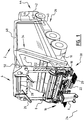
Figure 1 shows a view of a refuse truck provided with a loading system according to the invention; and -
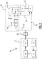
Figure 2 shows a schematic representation of the system according to the invention. - Refuse truck 2 (
Figure 1 ) with a collector and press is provided withloading system 4.Loading system 4 is used to empty bins 6. Bins 6 are, among others, bins of the type EN 840-1, -2, -3 and -4 with respective volumes of 80-360 litres, 500-1200 litres, 770, 1100, 1300 litres, and 750-1700 litres. It is optionally also possible to userefuse truck 2 to place refuse bags therein. Bin 6 is emptied intoloading opening 8 which is bounded on the sides by side walls or side shields 10 provided onrefuse truck 2. - In the shown
embodiment loading system 4 is provided with substantially the same width as that ofrefuse truck 2. The widestpossible loading opening 8 is hereby provided and bins of diverse dimensions can be emptied with optimal flexibility. Uprights 12 form the connection betweenloading system 4 and refusetruck 2. Mounted on uprights 12 in the shown embodiment are lifting arms 14 with which engagingmechanism 16 can be moved for the purpose of lifting bin 6.Engaging mechanism 16 is provided here with liftingshaft 18. Refusetruck 2 is also provided withfootboard 20. A dustman for instance can take up position onfootboard 20 during movement ofrefuse truck 2. Buffers orcarrier 22 are provided such that a bin 6 for emptying can rest thereon during the pivoting movement. The pivoting movement of bin 6 is carried out fromground surface 24. In the shown embodiment guides 26 are provided on or close to the top part ofloading system 4 for pushing open the lid of bin 6.Stop member 28 is preferably arranged here, preferably along substantially the whole width ofloading opening 8, in order to avoid bin 6 rotating too far, at least during the pivoting movement.Comb 30 of engagingmechanism 16 can engage under an edge of bin 6. Clamping plate or enclosingplate 32 is used to clamp the bin edge between thisplate 32 andcomb 30.Couplings 34connect loading system 4 to refusetruck 2 in preferably releasable manner. - Bin 6 is picked up during the emptying
cycle using comb 30 and clampingplate 32. During the lifting and tilting movement bin 6 rests on buffers orcarriers 22. Bin 6 is tilted by rotation around liftingshaft 18, wherein by opening the lid of bin 6 the content thereof is emptied intorefuse truck 2. - In the shown
embodiment energy module 36 is arranged as separate module for the purpose of providing energy to drive 38 ofloading system 4.Drive system 38 ofloading system 4 is of the electro-hydraulic type in the shown embodiment, in accordance with for instance that shown inEP 2 347 978 A1truck 2 is provided with battery orbattery pack 40 which is charged bycombustion engine 44 usingdynamo 42.Dynamo 42 is connected for this purpose to battery orbattery pack 40 via connectingline 46. Battery orbattery pack 40 is connected viacable 48 to separateenergy module 50.Module 50 is operatively connected to control 52 ofloading system 8 bycable 54. - Refuse truck 2 (
Figure 2 ) is provided with aconventional connection 56 for electricity users.Connection 56 is arranged at battery orbattery pack 40 which is charged with charging current device ordynamo 42 usingengine 44.Energy module 50 is connected viamain relay 58 toconnection 56 ofrefuse truck 2. - In the shown
embodiment energy module 50 is provided with chargingdevice 60 which is connected viacable 48 tomain relay 58. Chargingdevice 60charges capacitor 62 via chargingcable 64.Capacitor 62 is connected viaenergy module relay 68 andcable 70 toloading system 4.Control 52 is operatively connected viaconnection 74 toloading system 4 for the purpose of passing commands toloading system 4.Control 52 is operatively connected viaconnection 76 to relay 68 for switching thereof.Capacitor 62 can be controlled or read bycontrol 52 viaconnection 78. - In the shown embodiment it is possible to provide the total energy required for
loading system 4 fromenergy module 50, and inparticular capacitor 62. This latter is charged fromrefuse truck 2 via chargingcable 48 between emptying of bins 6. It is optionally also possible to use energy from battery orbattery pack 40 via connectingcable 72 for the purpose of controllingloading system 4. This is particularly relevant when it is not possible to sufficiently chargecapacitor 62 between emptying of one or more bins 6. - In the shown
embodiment energy module 50 is provided as separate module atloading system 4. This also makes application possible with existing electrically driven loading systems. It will be apparent that it is likewise possible according to the invention to provideenergy module 50 in integrated manner in or onloading system 4. - In the shown
embodiment capacitor 62 is provided with a voltage of between 2 and 3 V, preferably about 2.85 V, and has a capacitance of 3400 F. It will be apparent that more than onecapacitor 62 can also be used in an alternative configuration ofenergy module 50. - It will likewise be apparent that further alternative configurations are also possible according to the invention. It is thus possible for instance to replace or supplement battery or battery packs 40 with other energy supplies, including for instance a fuel cell. It is also possible to have battery or
battery pack 40 alternatively or additionally charged with charging systems from external charging sources. - Experiments with
loading system 4 demonstrate that it is possible, with a correct dimensioning ofenergy module 50, and inparticular capacitor 62, to perform a complete emptying cycle of bin 6. It is thus even possible to empty three to four bins 6 with a single charge ofcapacitor 62. In such an embodiment it is possible to have the power supply toloading system 4 for the purpose of emptying bins 6 provided wholly byenergy module 50. In an alternative embodiment battery orbattery pack 40 is also operatively connected toloading system 4 for the purpose of supplying energy, for instance when a plurality of bins 6 have to be emptied in quick succession. Experiments have demonstrated that by applyingmodule 50 it is possible to comply with the energy-specific construction guidelines usually applying to the chassis ofrefuse truck 2. - Further experiments demonstrate that, when
conventional loading systems 4 are used inconventional refuse trucks 2, i.e. withoutenergy module 50, relatively high currents flow through connectingcables 48, particularly during lifting of heavy bins 6. A loss of voltage of up to 5 V can hereby occur in a battery orbattery pack 40 operating at 24 V. This limits the capacitance ofloading system 4. By applyingenergy module 50 this loss can be limited in similar conditions to less than 1 V such that the capacitance ofloading system 4 increases significantly without components of the loading system having to be modified. This is achieved in thatenergy module 50 provides for the necessary high current peak. It is thus found that during lifting of bins 6 with maximum load the current drawn frombattery 40 and chargingdevice 42 is about 60% lower than in similar conventional loading systems. - The present invention is by no means limited to the above described preferred embodiments thereof. The rights sought are defined by the following claims, within the scope of which many modifications can be envisaged.
Claims (13)
- Loading system (4) for lifting and emptying a bin (6) into a collector, the loading system (4) comprising:- a frame attachable with coupling means to the collector;- a lifting mechanism (14, 16) arranged on the frame for picking up and lifting the bin (6);- a lifting drive system (38) operatively connected to the lifting mechanism (14, 16),
wherein the lifting drive system (38) comprises:- a lifting drive (38) provided with a power supply connection (70,72) and configured to drive the lifting mechanism; and- an energy module (50) comprising a capacitor (62) for providing energy to the lifting drive via the power supply connection, characterised in that the energy module (50) is provided with connecting means (48) for operatively connecting the energy module (50) to an energy supply (36), and wherein the power supply connection (70,72) is provided with first connecting means (70) for providing energy from the energy module (50) and second connecting means (72) for providing energy from the energy supply (36). - Loading system (4) as claimed in claim 1, wherein the energy module (50) comprises a charging circuit (60) for charging the capacitor (62).
- Loading system (4) as claimed in claim 1 or 2, wherein the capacitor (62) comprises a supercapacitor.
- Loading system (4) as claimed in claim 1, 2 or 3, wherein the energy module (50) is provided with an energy module relay (68) arranged between the capacitor and the lifting mechanism.
- Loading system (4) as claimed in any of the foregoing claims, further comprising a main relay (58) arranged between the energy module (50) and energy supply (36).
- Loading system (4) as claimed in claim 1 or 5, wherein the energy supply (36) comprises a vehicle battery (40).
- Loading system (4) as claimed in claim 6, wherein the vehicle battery (40) comprises a 24 V battery.
- Loading system (4) as claimed in any of the foregoing claims, further comprising a lifting control (52) for controlling the lifting mechanism (14, 16), wherein the lifting control (52) is configured to control the energy module (50).
- Loading system as claimed in any of the foregoing claims, further comprising energy recovery means for charging the capacitor (62) of the energy module (50) during setting down of a bin (6).
- Refuse truck (2) provided with a loading system (4) as claimed in any of the foregoing claims.
- Refuse truck (2) as claimed in claim 10, further comprising an energy recovery system for recovering energy from the vehicle and charging the capacitor (62) of the energy module (50) therewith.
- Method for emptying a bin (6), the method comprising the steps of:- providing a loading system (4) and/or refuse truck (2) as claimed in any of the foregoing claims;- picking up the bin (6) to be emptied with the loading system (4);- lifting and emptying the bin (6); and- setting down the emptied bin (6).
- Method as claimed in claim 12, further comprising the step of providing energy to the lifting mechanism (14, 16) with the energy module (50) such that the lifting mechanism (14, 16) can perform a full emptying cycle with pick-up, lifting, emptying and setting down of a bin (6).
Priority Applications (1)
| Application Number | Priority Date | Filing Date | Title |
|---|---|---|---|
| PL18201301T PL3473482T3 (en) | 2017-10-18 | 2018-10-18 | Loading system having an energy module, refuse truck with such a system and implementing method |
Applications Claiming Priority (1)
| Application Number | Priority Date | Filing Date | Title |
|---|---|---|---|
| NL2019751A NL2019751B1 (en) | 2017-10-18 | 2017-10-18 | LOADING SYSTEM PROVIDED FOR AN ENERGY MODULE, WASTE CAR PROVIDED THEREOF AND METHOD THEREFOR |
Publications (2)
| Publication Number | Publication Date |
|---|---|
| EP3473482A1 EP3473482A1 (en) | 2019-04-24 |
| EP3473482B1 true EP3473482B1 (en) | 2020-12-02 |
Family
ID=60294375
Family Applications (1)
| Application Number | Title | Priority Date | Filing Date |
|---|---|---|---|
| EP18201301.1A Active EP3473482B1 (en) | 2017-10-18 | 2018-10-18 | Loading system having an energy module, refuse truck with such a system and implementing method |
Country Status (7)
| Country | Link |
|---|---|
| EP (1) | EP3473482B1 (en) |
| DK (1) | DK3473482T3 (en) |
| ES (1) | ES2847474T3 (en) |
| LT (1) | LT3473482T (en) |
| NL (1) | NL2019751B1 (en) |
| PL (1) | PL3473482T3 (en) |
| PT (1) | PT3473482T (en) |
Family Cites Families (5)
| Publication number | Priority date | Publication date | Assignee | Title |
|---|---|---|---|---|
| WO2009087552A2 (en) * | 2007-12-31 | 2009-07-16 | Renault Trucks | Hybrid vehicle for transportation of a refrigerated commercial load |
| NL2004148C2 (en) * | 2010-01-26 | 2011-07-27 | Terberg Machines | LOADING SYSTEM, DIRTY CAR AND METHOD FOR THIS. |
| EP2383859A1 (en) * | 2010-04-28 | 2011-11-02 | Fabio Brucchi | Fast rechargeable electric system for stand-alone power sources |
| WO2013008331A1 (en) * | 2011-07-14 | 2013-01-17 | 新明和工業株式会社 | Refuse collection vehicle |
| CA2825719C (en) * | 2013-08-27 | 2016-05-10 | Haul-All Equipment Ltd. | Waste collection vehicle with raised and sloped hopper |
-
2017
- 2017-10-18 NL NL2019751A patent/NL2019751B1/en not_active IP Right Cessation
-
2018
- 2018-10-18 PT PT182013011T patent/PT3473482T/en unknown
- 2018-10-18 PL PL18201301T patent/PL3473482T3/en unknown
- 2018-10-18 ES ES18201301T patent/ES2847474T3/en active Active
- 2018-10-18 EP EP18201301.1A patent/EP3473482B1/en active Active
- 2018-10-18 DK DK18201301.1T patent/DK3473482T3/en active
- 2018-10-18 LT LTEP18201301.1T patent/LT3473482T/en unknown
Non-Patent Citations (1)
| Title |
|---|
| None * |
Also Published As
| Publication number | Publication date |
|---|---|
| NL2019751B1 (en) | 2019-04-25 |
| EP3473482A1 (en) | 2019-04-24 |
| LT3473482T (en) | 2021-02-25 |
| PT3473482T (en) | 2021-02-03 |
| ES2847474T3 (en) | 2021-08-03 |
| DK3473482T3 (en) | 2021-02-01 |
| PL3473482T3 (en) | 2021-05-31 |
Similar Documents
| Publication | Publication Date | Title |
|---|---|---|
| JP4862153B2 (en) | Power load leveling method and system | |
| US20110180287A1 (en) | Implement having a hybrid drive | |
| CN1208230C (en) | Apparatus and method for reducing mains connection power of elevator installations | |
| US9056752B2 (en) | Crane, in particular mobile port crane, comprising a hybrid drive system | |
| CA2769622C (en) | Electric charging apparatus | |
| DK2372864T3 (en) | Autonomous motorization system | |
| EP2527219A1 (en) | Drive control device for working vehicle | |
| CN102470762A (en) | Electric-vehicle propulsion power-conversion device | |
| WO2007048112A2 (en) | Lift truck with hybrid power source | |
| EP2151097A2 (en) | Energy recapture for an industrial vehicle | |
| US20210146780A1 (en) | System for an electrically driven vehicle, and vehicle therewith and method therefor | |
| EP2653339A2 (en) | A piggyback forklift truck and a method of operating same | |
| CN110915092A (en) | Power supply apparatus and track-type vehicle | |
| JP5015073B2 (en) | Charging system | |
| CN116587901B (en) | Standing driving type mobile charging vehicle | |
| US11374430B2 (en) | Device for the emergency supply of a high voltage onboard network | |
| EP2501015B1 (en) | Power supply system | |
| DE102008012406A1 (en) | Drive arrangement for ground conveyor, has fuel cell and short-time storage, where battery is provided as additional energy storage, and battery is designed as lead-acid battery | |
| GB2607995A (en) | Road building machine, and method for operating the road building machine | |
| CN215322084U (en) | Energy storage type direct current charging pile | |
| EP2347978B1 (en) | Loading system for lifting and emptying a container | |
| CN108162769A (en) | The dynamical system and its control method of off-highway electric power wheel self-discharging vehicle | |
| EP3473482A1 (en) | Loading system having an energy module, refuse truck with such a system and implementing method | |
| DE102010013670A1 (en) | Double hybrid storage system | |
| JP6189010B2 (en) | Crane and power supply method for crane |
Legal Events
| Date | Code | Title | Description |
|---|---|---|---|
| PUAI | Public reference made under article 153(3) epc to a published international application that has entered the european phase |
Free format text: ORIGINAL CODE: 0009012 |
|
| STAA | Information on the status of an ep patent application or granted ep patent |
Free format text: STATUS: THE APPLICATION HAS BEEN PUBLISHED |
|
| AK | Designated contracting states |
Kind code of ref document: A1 Designated state(s): AL AT BE BG CH CY CZ DE DK EE ES FI FR GB GR HR HU IE IS IT LI LT LU LV MC MK MT NL NO PL PT RO RS SE SI SK SM TR |
|
| AX | Request for extension of the european patent |
Extension state: BA ME |
|
| STAA | Information on the status of an ep patent application or granted ep patent |
Free format text: STATUS: REQUEST FOR EXAMINATION WAS MADE |
|
| 17P | Request for examination filed |
Effective date: 20191011 |
|
| RBV | Designated contracting states (corrected) |
Designated state(s): AL AT BE BG CH CY CZ DE DK EE ES FI FR GB GR HR HU IE IS IT LI LT LU LV MC MK MT NL NO PL PT RO RS SE SI SK SM TR |
|
| RIC1 | Information provided on ipc code assigned before grant |
Ipc: B65G 65/23 20060101ALI20200317BHEP Ipc: B65F 3/00 20060101ALI20200317BHEP Ipc: B65F 3/02 20060101ALI20200317BHEP Ipc: B60L 1/00 20060101AFI20200317BHEP Ipc: B60L 7/10 20060101ALI20200317BHEP Ipc: B60L 50/40 20190101ALN20200317BHEP Ipc: B60L 50/50 20190101ALN20200317BHEP Ipc: B65F 3/24 20060101ALI20200317BHEP |
|
| RIC1 | Information provided on ipc code assigned before grant |
Ipc: B60L 50/50 20190101ALN20200529BHEP Ipc: B65F 3/24 20060101ALI20200529BHEP Ipc: B65G 65/23 20060101ALI20200529BHEP Ipc: B65F 3/02 20060101ALI20200529BHEP Ipc: B60L 7/10 20060101ALI20200529BHEP Ipc: B60L 1/00 20060101AFI20200529BHEP Ipc: B65F 3/00 20060101ALI20200529BHEP Ipc: B60L 50/40 20190101ALN20200529BHEP |
|
| GRAP | Despatch of communication of intention to grant a patent |
Free format text: ORIGINAL CODE: EPIDOSNIGR1 |
|
| STAA | Information on the status of an ep patent application or granted ep patent |
Free format text: STATUS: GRANT OF PATENT IS INTENDED |
|
| INTG | Intention to grant announced |
Effective date: 20200713 |
|
| GRAS | Grant fee paid |
Free format text: ORIGINAL CODE: EPIDOSNIGR3 |
|
| GRAA | (expected) grant |
Free format text: ORIGINAL CODE: 0009210 |
|
| STAA | Information on the status of an ep patent application or granted ep patent |
Free format text: STATUS: THE PATENT HAS BEEN GRANTED |
|
| AK | Designated contracting states |
Kind code of ref document: B1 Designated state(s): AL AT BE BG CH CY CZ DE DK EE ES FI FR GB GR HR HU IE IS IT LI LT LU LV MC MK MT NL NO PL PT RO RS SE SI SK SM TR |
|
| REG | Reference to a national code |
Ref country code: GB Ref legal event code: FG4D |
|
| REG | Reference to a national code |
Ref country code: AT Ref legal event code: REF Ref document number: 1340538 Country of ref document: AT Kind code of ref document: T Effective date: 20201215 Ref country code: CH Ref legal event code: EP |
|
| REG | Reference to a national code |
Ref country code: IE Ref legal event code: FG4D |
|
| REG | Reference to a national code |
Ref country code: DE Ref legal event code: R096 Ref document number: 602018010360 Country of ref document: DE |
|
| REG | Reference to a national code |
Ref country code: NL Ref legal event code: FP |
|
| REG | Reference to a national code |
Ref country code: DK Ref legal event code: T3 Effective date: 20210126 |
|
| REG | Reference to a national code |
Ref country code: PT Ref legal event code: SC4A Ref document number: 3473482 Country of ref document: PT Date of ref document: 20210203 Kind code of ref document: T Free format text: AVAILABILITY OF NATIONAL TRANSLATION Effective date: 20210126 |
|
| REG | Reference to a national code |
Ref country code: SE Ref legal event code: TRGR |
|
| REG | Reference to a national code |
Ref country code: EE Ref legal event code: FG4A Ref document number: E020415 Country of ref document: EE Effective date: 20210210 |
|
| REG | Reference to a national code |
Ref country code: NO Ref legal event code: T2 Effective date: 20201202 |
|
| PG25 | Lapsed in a contracting state [announced via postgrant information from national office to epo] |
Ref country code: RS Free format text: LAPSE BECAUSE OF FAILURE TO SUBMIT A TRANSLATION OF THE DESCRIPTION OR TO PAY THE FEE WITHIN THE PRESCRIBED TIME-LIMIT Effective date: 20201202 Ref country code: FI Free format text: LAPSE BECAUSE OF FAILURE TO SUBMIT A TRANSLATION OF THE DESCRIPTION OR TO PAY THE FEE WITHIN THE PRESCRIBED TIME-LIMIT Effective date: 20201202 Ref country code: GR Free format text: LAPSE BECAUSE OF FAILURE TO SUBMIT A TRANSLATION OF THE DESCRIPTION OR TO PAY THE FEE WITHIN THE PRESCRIBED TIME-LIMIT Effective date: 20210303 |
|
| PG25 | Lapsed in a contracting state [announced via postgrant information from national office to epo] |
Ref country code: BG Free format text: LAPSE BECAUSE OF FAILURE TO SUBMIT A TRANSLATION OF THE DESCRIPTION OR TO PAY THE FEE WITHIN THE PRESCRIBED TIME-LIMIT Effective date: 20210302 |
|
| PG25 | Lapsed in a contracting state [announced via postgrant information from national office to epo] |
Ref country code: HR Free format text: LAPSE BECAUSE OF FAILURE TO SUBMIT A TRANSLATION OF THE DESCRIPTION OR TO PAY THE FEE WITHIN THE PRESCRIBED TIME-LIMIT Effective date: 20201202 |
|
| PG25 | Lapsed in a contracting state [announced via postgrant information from national office to epo] |
Ref country code: RO Free format text: LAPSE BECAUSE OF FAILURE TO SUBMIT A TRANSLATION OF THE DESCRIPTION OR TO PAY THE FEE WITHIN THE PRESCRIBED TIME-LIMIT Effective date: 20201202 Ref country code: SM Free format text: LAPSE BECAUSE OF FAILURE TO SUBMIT A TRANSLATION OF THE DESCRIPTION OR TO PAY THE FEE WITHIN THE PRESCRIBED TIME-LIMIT Effective date: 20201202 Ref country code: SK Free format text: LAPSE BECAUSE OF FAILURE TO SUBMIT A TRANSLATION OF THE DESCRIPTION OR TO PAY THE FEE WITHIN THE PRESCRIBED TIME-LIMIT Effective date: 20201202 Ref country code: CZ Free format text: LAPSE BECAUSE OF FAILURE TO SUBMIT A TRANSLATION OF THE DESCRIPTION OR TO PAY THE FEE WITHIN THE PRESCRIBED TIME-LIMIT Effective date: 20201202 |
|
| REG | Reference to a national code |
Ref country code: ES Ref legal event code: FG2A Ref document number: 2847474 Country of ref document: ES Kind code of ref document: T3 Effective date: 20210803 |
|
| REG | Reference to a national code |
Ref country code: DE Ref legal event code: R097 Ref document number: 602018010360 Country of ref document: DE |
|
| PG25 | Lapsed in a contracting state [announced via postgrant information from national office to epo] |
Ref country code: IS Free format text: LAPSE BECAUSE OF FAILURE TO SUBMIT A TRANSLATION OF THE DESCRIPTION OR TO PAY THE FEE WITHIN THE PRESCRIBED TIME-LIMIT Effective date: 20210402 |
|
| PLBE | No opposition filed within time limit |
Free format text: ORIGINAL CODE: 0009261 |
|
| STAA | Information on the status of an ep patent application or granted ep patent |
Free format text: STATUS: NO OPPOSITION FILED WITHIN TIME LIMIT |
|
| PG25 | Lapsed in a contracting state [announced via postgrant information from national office to epo] |
Ref country code: AL Free format text: LAPSE BECAUSE OF FAILURE TO SUBMIT A TRANSLATION OF THE DESCRIPTION OR TO PAY THE FEE WITHIN THE PRESCRIBED TIME-LIMIT Effective date: 20201202 |
|
| 26N | No opposition filed |
Effective date: 20210903 |
|
| PG25 | Lapsed in a contracting state [announced via postgrant information from national office to epo] |
Ref country code: SI Free format text: LAPSE BECAUSE OF FAILURE TO SUBMIT A TRANSLATION OF THE DESCRIPTION OR TO PAY THE FEE WITHIN THE PRESCRIBED TIME-LIMIT Effective date: 20201202 |
|
| REG | Reference to a national code |
Ref country code: CH Ref legal event code: PL |
|
| PG25 | Lapsed in a contracting state [announced via postgrant information from national office to epo] |
Ref country code: IS Free format text: LAPSE BECAUSE OF FAILURE TO SUBMIT A TRANSLATION OF THE DESCRIPTION OR TO PAY THE FEE WITHIN THE PRESCRIBED TIME-LIMIT Effective date: 20210402 |
|
| PG25 | Lapsed in a contracting state [announced via postgrant information from national office to epo] |
Ref country code: MC Free format text: LAPSE BECAUSE OF FAILURE TO SUBMIT A TRANSLATION OF THE DESCRIPTION OR TO PAY THE FEE WITHIN THE PRESCRIBED TIME-LIMIT Effective date: 20201202 |
|
| PG25 | Lapsed in a contracting state [announced via postgrant information from national office to epo] |
Ref country code: LU Free format text: LAPSE BECAUSE OF NON-PAYMENT OF DUE FEES Effective date: 20211018 |
|
| PG25 | Lapsed in a contracting state [announced via postgrant information from national office to epo] |
Ref country code: LI Free format text: LAPSE BECAUSE OF NON-PAYMENT OF DUE FEES Effective date: 20211031 Ref country code: CH Free format text: LAPSE BECAUSE OF NON-PAYMENT OF DUE FEES Effective date: 20211031 |
|
| REG | Reference to a national code |
Ref country code: AT Ref legal event code: UEP Ref document number: 1340538 Country of ref document: AT Kind code of ref document: T Effective date: 20201202 |
|
| P01 | Opt-out of the competence of the unified patent court (upc) registered |
Effective date: 20230515 |
|
| PG25 | Lapsed in a contracting state [announced via postgrant information from national office to epo] |
Ref country code: CY Free format text: LAPSE BECAUSE OF FAILURE TO SUBMIT A TRANSLATION OF THE DESCRIPTION OR TO PAY THE FEE WITHIN THE PRESCRIBED TIME-LIMIT Effective date: 20201202 |
|
| PG25 | Lapsed in a contracting state [announced via postgrant information from national office to epo] |
Ref country code: HU Free format text: LAPSE BECAUSE OF FAILURE TO SUBMIT A TRANSLATION OF THE DESCRIPTION OR TO PAY THE FEE WITHIN THE PRESCRIBED TIME-LIMIT; INVALID AB INITIO Effective date: 20181018 |
|
| PG25 | Lapsed in a contracting state [announced via postgrant information from national office to epo] |
Ref country code: MK Free format text: LAPSE BECAUSE OF FAILURE TO SUBMIT A TRANSLATION OF THE DESCRIPTION OR TO PAY THE FEE WITHIN THE PRESCRIBED TIME-LIMIT Effective date: 20201202 |
|
| PG25 | Lapsed in a contracting state [announced via postgrant information from national office to epo] |
Ref country code: MT Free format text: LAPSE BECAUSE OF FAILURE TO SUBMIT A TRANSLATION OF THE DESCRIPTION OR TO PAY THE FEE WITHIN THE PRESCRIBED TIME-LIMIT Effective date: 20201202 |
|
| PGFP | Annual fee paid to national office [announced via postgrant information from national office to epo] |
Ref country code: NL Payment date: 20251026 Year of fee payment: 8 |
|
| PGFP | Annual fee paid to national office [announced via postgrant information from national office to epo] |
Ref country code: PT Payment date: 20251002 Year of fee payment: 8 |
|
| PG25 | Lapsed in a contracting state [announced via postgrant information from national office to epo] |
Ref country code: TR Free format text: LAPSE BECAUSE OF FAILURE TO SUBMIT A TRANSLATION OF THE DESCRIPTION OR TO PAY THE FEE WITHIN THE PRESCRIBED TIME-LIMIT Effective date: 20201202 |
|
| PGFP | Annual fee paid to national office [announced via postgrant information from national office to epo] |
Ref country code: DE Payment date: 20251029 Year of fee payment: 8 |
|
| PGFP | Annual fee paid to national office [announced via postgrant information from national office to epo] |
Ref country code: LT Payment date: 20251001 Year of fee payment: 8 Ref country code: GB Payment date: 20251027 Year of fee payment: 8 |
|
| PGFP | Annual fee paid to national office [announced via postgrant information from national office to epo] |
Ref country code: NO Payment date: 20251029 Year of fee payment: 8 |
|
| PGFP | Annual fee paid to national office [announced via postgrant information from national office to epo] |
Ref country code: AT Payment date: 20251029 Year of fee payment: 8 |
|
| PGFP | Annual fee paid to national office [announced via postgrant information from national office to epo] |
Ref country code: DK Payment date: 20251027 Year of fee payment: 8 Ref country code: IT Payment date: 20251021 Year of fee payment: 8 |
|
| PGFP | Annual fee paid to national office [announced via postgrant information from national office to epo] |
Ref country code: FR Payment date: 20251027 Year of fee payment: 8 |
|
| PGFP | Annual fee paid to national office [announced via postgrant information from national office to epo] |
Ref country code: BE Payment date: 20251027 Year of fee payment: 8 |
|
| PGFP | Annual fee paid to national office [announced via postgrant information from national office to epo] |
Ref country code: SE Payment date: 20251027 Year of fee payment: 8 |
|
| PGFP | Annual fee paid to national office [announced via postgrant information from national office to epo] |
Ref country code: IE Payment date: 20251027 Year of fee payment: 8 |
|
| PGFP | Annual fee paid to national office [announced via postgrant information from national office to epo] |
Ref country code: LV Payment date: 20251001 Year of fee payment: 8 |
|
| PGFP | Annual fee paid to national office [announced via postgrant information from national office to epo] |
Ref country code: PL Payment date: 20251003 Year of fee payment: 8 |
|
| PGFP | Annual fee paid to national office [announced via postgrant information from national office to epo] |
Ref country code: EE Payment date: 20251009 Year of fee payment: 8 |
|
| PGFP | Annual fee paid to national office [announced via postgrant information from national office to epo] |
Ref country code: ES Payment date: 20251103 Year of fee payment: 8 |