EP3473437B2 - Mehrlagiger folienverbund sowie verfahren zur herstellung eines mehrlagigen folienverbundes - Google Patents
Mehrlagiger folienverbund sowie verfahren zur herstellung eines mehrlagigen folienverbundes Download PDFInfo
- Publication number
- EP3473437B2 EP3473437B2 EP18196314.1A EP18196314A EP3473437B2 EP 3473437 B2 EP3473437 B2 EP 3473437B2 EP 18196314 A EP18196314 A EP 18196314A EP 3473437 B2 EP3473437 B2 EP 3473437B2
- Authority
- EP
- European Patent Office
- Prior art keywords
- film
- film composite
- embossed
- welding
- pattern
- Prior art date
- Legal status (The legal status is an assumption and is not a legal conclusion. Google has not performed a legal analysis and makes no representation as to the accuracy of the status listed.)
- Active
Links
Images



Classifications
-
- B—PERFORMING OPERATIONS; TRANSPORTING
- B29—WORKING OF PLASTICS; WORKING OF SUBSTANCES IN A PLASTIC STATE IN GENERAL
- B29C—SHAPING OR JOINING OF PLASTICS; SHAPING OF MATERIAL IN A PLASTIC STATE, NOT OTHERWISE PROVIDED FOR; AFTER-TREATMENT OF THE SHAPED PRODUCTS, e.g. REPAIRING
- B29C66/00—General aspects of processes or apparatus for joining preformed parts
- B29C66/01—General aspects dealing with the joint area or with the area to be joined
- B29C66/05—Particular design of joint configurations
- B29C66/306—Applying a mark during joining
-
- B—PERFORMING OPERATIONS; TRANSPORTING
- B29—WORKING OF PLASTICS; WORKING OF SUBSTANCES IN A PLASTIC STATE IN GENERAL
- B29C—SHAPING OR JOINING OF PLASTICS; SHAPING OF MATERIAL IN A PLASTIC STATE, NOT OTHERWISE PROVIDED FOR; AFTER-TREATMENT OF THE SHAPED PRODUCTS, e.g. REPAIRING
- B29C65/00—Joining or sealing of preformed parts, e.g. welding of plastics materials; Apparatus therefor
- B29C65/02—Joining or sealing of preformed parts, e.g. welding of plastics materials; Apparatus therefor by heating, with or without pressure
- B29C65/18—Joining or sealing of preformed parts, e.g. welding of plastics materials; Apparatus therefor by heating, with or without pressure using heated tools
-
- B—PERFORMING OPERATIONS; TRANSPORTING
- B29—WORKING OF PLASTICS; WORKING OF SUBSTANCES IN A PLASTIC STATE IN GENERAL
- B29C—SHAPING OR JOINING OF PLASTICS; SHAPING OF MATERIAL IN A PLASTIC STATE, NOT OTHERWISE PROVIDED FOR; AFTER-TREATMENT OF THE SHAPED PRODUCTS, e.g. REPAIRING
- B29C65/00—Joining or sealing of preformed parts, e.g. welding of plastics materials; Apparatus therefor
- B29C65/74—Joining or sealing of preformed parts, e.g. welding of plastics materials; Apparatus therefor by welding and severing, or by joining and severing, the severing being performed in the area to be joined, next to the area to be joined, in the joint area or next to the joint area
- B29C65/743—Joining or sealing of preformed parts, e.g. welding of plastics materials; Apparatus therefor by welding and severing, or by joining and severing, the severing being performed in the area to be joined, next to the area to be joined, in the joint area or next to the joint area using the same tool for both joining and severing, said tool being monobloc or formed by several parts mounted together and forming a monobloc
- B29C65/7437—Joining or sealing of preformed parts, e.g. welding of plastics materials; Apparatus therefor by welding and severing, or by joining and severing, the severing being performed in the area to be joined, next to the area to be joined, in the joint area or next to the joint area using the same tool for both joining and severing, said tool being monobloc or formed by several parts mounted together and forming a monobloc the tool being a perforating tool
-
- B—PERFORMING OPERATIONS; TRANSPORTING
- B29—WORKING OF PLASTICS; WORKING OF SUBSTANCES IN A PLASTIC STATE IN GENERAL
- B29C—SHAPING OR JOINING OF PLASTICS; SHAPING OF MATERIAL IN A PLASTIC STATE, NOT OTHERWISE PROVIDED FOR; AFTER-TREATMENT OF THE SHAPED PRODUCTS, e.g. REPAIRING
- B29C66/00—General aspects of processes or apparatus for joining preformed parts
- B29C66/004—Preventing sticking together, e.g. of some areas of the parts to be joined
- B29C66/0042—Preventing sticking together, e.g. of some areas of the parts to be joined of the joining tool and the parts to be joined
-
- B—PERFORMING OPERATIONS; TRANSPORTING
- B29—WORKING OF PLASTICS; WORKING OF SUBSTANCES IN A PLASTIC STATE IN GENERAL
- B29C—SHAPING OR JOINING OF PLASTICS; SHAPING OF MATERIAL IN A PLASTIC STATE, NOT OTHERWISE PROVIDED FOR; AFTER-TREATMENT OF THE SHAPED PRODUCTS, e.g. REPAIRING
- B29C66/00—General aspects of processes or apparatus for joining preformed parts
- B29C66/01—General aspects dealing with the joint area or with the area to be joined
- B29C66/05—Particular design of joint configurations
- B29C66/10—Particular design of joint configurations particular design of the joint cross-sections
- B29C66/11—Joint cross-sections comprising a single joint-segment, i.e. one of the parts to be joined comprising a single joint-segment in the joint cross-section
- B29C66/112—Single lapped joints
- B29C66/1122—Single lap to lap joints, i.e. overlap joints
-
- B—PERFORMING OPERATIONS; TRANSPORTING
- B29—WORKING OF PLASTICS; WORKING OF SUBSTANCES IN A PLASTIC STATE IN GENERAL
- B29C—SHAPING OR JOINING OF PLASTICS; SHAPING OF MATERIAL IN A PLASTIC STATE, NOT OTHERWISE PROVIDED FOR; AFTER-TREATMENT OF THE SHAPED PRODUCTS, e.g. REPAIRING
- B29C66/00—General aspects of processes or apparatus for joining preformed parts
- B29C66/01—General aspects dealing with the joint area or with the area to be joined
- B29C66/05—Particular design of joint configurations
- B29C66/10—Particular design of joint configurations particular design of the joint cross-sections
- B29C66/13—Single flanged joints; Fin-type joints; Single hem joints; Edge joints; Interpenetrating fingered joints; Other specific particular designs of joint cross-sections not provided for in groups B29C66/11 - B29C66/12
- B29C66/133—Fin-type joints, the parts to be joined being flexible
-
- B—PERFORMING OPERATIONS; TRANSPORTING
- B29—WORKING OF PLASTICS; WORKING OF SUBSTANCES IN A PLASTIC STATE IN GENERAL
- B29C—SHAPING OR JOINING OF PLASTICS; SHAPING OF MATERIAL IN A PLASTIC STATE, NOT OTHERWISE PROVIDED FOR; AFTER-TREATMENT OF THE SHAPED PRODUCTS, e.g. REPAIRING
- B29C66/00—General aspects of processes or apparatus for joining preformed parts
- B29C66/01—General aspects dealing with the joint area or with the area to be joined
- B29C66/05—Particular design of joint configurations
- B29C66/20—Particular design of joint configurations particular design of the joint lines, e.g. of the weld lines
- B29C66/21—Particular design of joint configurations particular design of the joint lines, e.g. of the weld lines said joint lines being formed by a single dot or dash or by several dots or dashes, i.e. spot joining or spot welding
-
- B—PERFORMING OPERATIONS; TRANSPORTING
- B29—WORKING OF PLASTICS; WORKING OF SUBSTANCES IN A PLASTIC STATE IN GENERAL
- B29C—SHAPING OR JOINING OF PLASTICS; SHAPING OF MATERIAL IN A PLASTIC STATE, NOT OTHERWISE PROVIDED FOR; AFTER-TREATMENT OF THE SHAPED PRODUCTS, e.g. REPAIRING
- B29C66/00—General aspects of processes or apparatus for joining preformed parts
- B29C66/01—General aspects dealing with the joint area or with the area to be joined
- B29C66/05—Particular design of joint configurations
- B29C66/20—Particular design of joint configurations particular design of the joint lines, e.g. of the weld lines
- B29C66/22—Particular design of joint configurations particular design of the joint lines, e.g. of the weld lines said joint lines being in the form of recurring patterns
- B29C66/229—Other specific patterns not provided for in B29C66/221 - B29C66/227
-
- B—PERFORMING OPERATIONS; TRANSPORTING
- B29—WORKING OF PLASTICS; WORKING OF SUBSTANCES IN A PLASTIC STATE IN GENERAL
- B29C—SHAPING OR JOINING OF PLASTICS; SHAPING OF MATERIAL IN A PLASTIC STATE, NOT OTHERWISE PROVIDED FOR; AFTER-TREATMENT OF THE SHAPED PRODUCTS, e.g. REPAIRING
- B29C66/00—General aspects of processes or apparatus for joining preformed parts
- B29C66/01—General aspects dealing with the joint area or with the area to be joined
- B29C66/05—Particular design of joint configurations
- B29C66/20—Particular design of joint configurations particular design of the joint lines, e.g. of the weld lines
- B29C66/23—Particular design of joint configurations particular design of the joint lines, e.g. of the weld lines said joint lines being multiple and parallel or being in the form of tessellations
- B29C66/234—Particular design of joint configurations particular design of the joint lines, e.g. of the weld lines said joint lines being multiple and parallel or being in the form of tessellations said joint lines being in the form of tessellations
-
- B—PERFORMING OPERATIONS; TRANSPORTING
- B29—WORKING OF PLASTICS; WORKING OF SUBSTANCES IN A PLASTIC STATE IN GENERAL
- B29C—SHAPING OR JOINING OF PLASTICS; SHAPING OF MATERIAL IN A PLASTIC STATE, NOT OTHERWISE PROVIDED FOR; AFTER-TREATMENT OF THE SHAPED PRODUCTS, e.g. REPAIRING
- B29C66/00—General aspects of processes or apparatus for joining preformed parts
- B29C66/40—General aspects of joining substantially flat articles, e.g. plates, sheets or web-like materials; Making flat seams in tubular or hollow articles; Joining single elements to substantially flat surfaces
- B29C66/41—Joining substantially flat articles ; Making flat seams in tubular or hollow articles
- B29C66/43—Joining a relatively small portion of the surface of said articles
- B29C66/432—Joining a relatively small portion of the surface of said articles for making tubular articles or closed loops, e.g. by joining several sheets ; for making hollow articles or hollow preforms
- B29C66/4322—Joining a relatively small portion of the surface of said articles for making tubular articles or closed loops, e.g. by joining several sheets ; for making hollow articles or hollow preforms by joining a single sheet to itself
-
- B—PERFORMING OPERATIONS; TRANSPORTING
- B29—WORKING OF PLASTICS; WORKING OF SUBSTANCES IN A PLASTIC STATE IN GENERAL
- B29C—SHAPING OR JOINING OF PLASTICS; SHAPING OF MATERIAL IN A PLASTIC STATE, NOT OTHERWISE PROVIDED FOR; AFTER-TREATMENT OF THE SHAPED PRODUCTS, e.g. REPAIRING
- B29C66/00—General aspects of processes or apparatus for joining preformed parts
- B29C66/40—General aspects of joining substantially flat articles, e.g. plates, sheets or web-like materials; Making flat seams in tubular or hollow articles; Joining single elements to substantially flat surfaces
- B29C66/41—Joining substantially flat articles ; Making flat seams in tubular or hollow articles
- B29C66/45—Joining of substantially the whole surface of the articles
-
- B—PERFORMING OPERATIONS; TRANSPORTING
- B29—WORKING OF PLASTICS; WORKING OF SUBSTANCES IN A PLASTIC STATE IN GENERAL
- B29C—SHAPING OR JOINING OF PLASTICS; SHAPING OF MATERIAL IN A PLASTIC STATE, NOT OTHERWISE PROVIDED FOR; AFTER-TREATMENT OF THE SHAPED PRODUCTS, e.g. REPAIRING
- B29C66/00—General aspects of processes or apparatus for joining preformed parts
- B29C66/70—General aspects of processes or apparatus for joining preformed parts characterised by the composition, physical properties or the structure of the material of the parts to be joined; Joining with non-plastics material
- B29C66/71—General aspects of processes or apparatus for joining preformed parts characterised by the composition, physical properties or the structure of the material of the parts to be joined; Joining with non-plastics material characterised by the composition of the plastics material of the parts to be joined
-
- B—PERFORMING OPERATIONS; TRANSPORTING
- B29—WORKING OF PLASTICS; WORKING OF SUBSTANCES IN A PLASTIC STATE IN GENERAL
- B29C—SHAPING OR JOINING OF PLASTICS; SHAPING OF MATERIAL IN A PLASTIC STATE, NOT OTHERWISE PROVIDED FOR; AFTER-TREATMENT OF THE SHAPED PRODUCTS, e.g. REPAIRING
- B29C66/00—General aspects of processes or apparatus for joining preformed parts
- B29C66/70—General aspects of processes or apparatus for joining preformed parts characterised by the composition, physical properties or the structure of the material of the parts to be joined; Joining with non-plastics material
- B29C66/72—General aspects of processes or apparatus for joining preformed parts characterised by the composition, physical properties or the structure of the material of the parts to be joined; Joining with non-plastics material characterised by the structure of the material of the parts to be joined
- B29C66/723—General aspects of processes or apparatus for joining preformed parts characterised by the composition, physical properties or the structure of the material of the parts to be joined; Joining with non-plastics material characterised by the structure of the material of the parts to be joined being multi-layered
-
- B—PERFORMING OPERATIONS; TRANSPORTING
- B29—WORKING OF PLASTICS; WORKING OF SUBSTANCES IN A PLASTIC STATE IN GENERAL
- B29C—SHAPING OR JOINING OF PLASTICS; SHAPING OF MATERIAL IN A PLASTIC STATE, NOT OTHERWISE PROVIDED FOR; AFTER-TREATMENT OF THE SHAPED PRODUCTS, e.g. REPAIRING
- B29C66/00—General aspects of processes or apparatus for joining preformed parts
- B29C66/80—General aspects of machine operations or constructions and parts thereof
- B29C66/81—General aspects of the pressing elements, i.e. the elements applying pressure on the parts to be joined in the area to be joined, e.g. the welding jaws or clamps
- B29C66/812—General aspects of the pressing elements, i.e. the elements applying pressure on the parts to be joined in the area to be joined, e.g. the welding jaws or clamps characterised by the composition, by the structure, by the intensive physical properties or by the optical properties of the material constituting the pressing elements, e.g. constituting the welding jaws or clamps
- B29C66/8122—General aspects of the pressing elements, i.e. the elements applying pressure on the parts to be joined in the area to be joined, e.g. the welding jaws or clamps characterised by the composition, by the structure, by the intensive physical properties or by the optical properties of the material constituting the pressing elements, e.g. constituting the welding jaws or clamps characterised by the composition of the material constituting the pressing elements, e.g. constituting the welding jaws or clamps
-
- B—PERFORMING OPERATIONS; TRANSPORTING
- B29—WORKING OF PLASTICS; WORKING OF SUBSTANCES IN A PLASTIC STATE IN GENERAL
- B29C—SHAPING OR JOINING OF PLASTICS; SHAPING OF MATERIAL IN A PLASTIC STATE, NOT OTHERWISE PROVIDED FOR; AFTER-TREATMENT OF THE SHAPED PRODUCTS, e.g. REPAIRING
- B29C66/00—General aspects of processes or apparatus for joining preformed parts
- B29C66/80—General aspects of machine operations or constructions and parts thereof
- B29C66/81—General aspects of the pressing elements, i.e. the elements applying pressure on the parts to be joined in the area to be joined, e.g. the welding jaws or clamps
- B29C66/814—General aspects of the pressing elements, i.e. the elements applying pressure on the parts to be joined in the area to be joined, e.g. the welding jaws or clamps characterised by the design of the pressing elements, e.g. of the welding jaws or clamps
- B29C66/8141—General aspects of the pressing elements, i.e. the elements applying pressure on the parts to be joined in the area to be joined, e.g. the welding jaws or clamps characterised by the design of the pressing elements, e.g. of the welding jaws or clamps characterised by the surface geometry of the part of the pressing elements, e.g. welding jaws or clamps, coming into contact with the parts to be joined
- B29C66/81433—General aspects of the pressing elements, i.e. the elements applying pressure on the parts to be joined in the area to be joined, e.g. the welding jaws or clamps characterised by the design of the pressing elements, e.g. of the welding jaws or clamps characterised by the surface geometry of the part of the pressing elements, e.g. welding jaws or clamps, coming into contact with the parts to be joined being toothed, i.e. comprising several teeth or pins, or being patterned
-
- B—PERFORMING OPERATIONS; TRANSPORTING
- B29—WORKING OF PLASTICS; WORKING OF SUBSTANCES IN A PLASTIC STATE IN GENERAL
- B29C—SHAPING OR JOINING OF PLASTICS; SHAPING OF MATERIAL IN A PLASTIC STATE, NOT OTHERWISE PROVIDED FOR; AFTER-TREATMENT OF THE SHAPED PRODUCTS, e.g. REPAIRING
- B29C66/00—General aspects of processes or apparatus for joining preformed parts
- B29C66/80—General aspects of machine operations or constructions and parts thereof
- B29C66/83—General aspects of machine operations or constructions and parts thereof characterised by the movement of the joining or pressing tools
- B29C66/832—Reciprocating joining or pressing tools
- B29C66/8322—Joining or pressing tools reciprocating along one axis
-
- B—PERFORMING OPERATIONS; TRANSPORTING
- B29—WORKING OF PLASTICS; WORKING OF SUBSTANCES IN A PLASTIC STATE IN GENERAL
- B29C—SHAPING OR JOINING OF PLASTICS; SHAPING OF MATERIAL IN A PLASTIC STATE, NOT OTHERWISE PROVIDED FOR; AFTER-TREATMENT OF THE SHAPED PRODUCTS, e.g. REPAIRING
- B29C66/00—General aspects of processes or apparatus for joining preformed parts
- B29C66/80—General aspects of machine operations or constructions and parts thereof
- B29C66/83—General aspects of machine operations or constructions and parts thereof characterised by the movement of the joining or pressing tools
- B29C66/834—General aspects of machine operations or constructions and parts thereof characterised by the movement of the joining or pressing tools moving with the parts to be joined
- B29C66/8341—Roller, cylinder or drum types; Band or belt types; Ball types
- B29C66/83411—Roller, cylinder or drum types
- B29C66/83413—Roller, cylinder or drum types cooperating rollers, cylinders or drums
-
- B—PERFORMING OPERATIONS; TRANSPORTING
- B29—WORKING OF PLASTICS; WORKING OF SUBSTANCES IN A PLASTIC STATE IN GENERAL
- B29C—SHAPING OR JOINING OF PLASTICS; SHAPING OF MATERIAL IN A PLASTIC STATE, NOT OTHERWISE PROVIDED FOR; AFTER-TREATMENT OF THE SHAPED PRODUCTS, e.g. REPAIRING
- B29C66/00—General aspects of processes or apparatus for joining preformed parts
- B29C66/80—General aspects of machine operations or constructions and parts thereof
- B29C66/84—Specific machine types or machines suitable for specific applications
- B29C66/851—Bag or container making machines
- B29C66/8511—Bag making machines
-
- B—PERFORMING OPERATIONS; TRANSPORTING
- B32—LAYERED PRODUCTS
- B32B—LAYERED PRODUCTS, i.e. PRODUCTS BUILT-UP OF STRATA OF FLAT OR NON-FLAT, e.g. CELLULAR OR HONEYCOMB, FORM
- B32B27/00—Layered products comprising a layer of synthetic resin
- B32B27/06—Layered products comprising a layer of synthetic resin as the main or only constituent of a layer, which is next to another layer of the same or of a different material
-
- B—PERFORMING OPERATIONS; TRANSPORTING
- B32—LAYERED PRODUCTS
- B32B—LAYERED PRODUCTS, i.e. PRODUCTS BUILT-UP OF STRATA OF FLAT OR NON-FLAT, e.g. CELLULAR OR HONEYCOMB, FORM
- B32B3/00—Layered products comprising a layer with external or internal discontinuities or unevennesses, or a layer of non-planar shape; Layered products comprising a layer having particular features of form
- B32B3/26—Layered products comprising a layer with external or internal discontinuities or unevennesses, or a layer of non-planar shape; Layered products comprising a layer having particular features of form characterised by a particular shape of the outline of the cross-section of a continuous layer; characterised by a layer with cavities or internal voids ; characterised by an apertured layer
- B32B3/266—Layered products comprising a layer with external or internal discontinuities or unevennesses, or a layer of non-planar shape; Layered products comprising a layer having particular features of form characterised by a particular shape of the outline of the cross-section of a continuous layer; characterised by a layer with cavities or internal voids ; characterised by an apertured layer characterised by an apertured layer, the apertures going through the whole thickness of the layer, e.g. expanded metal, perforated layer, slit layer regular cells B32B3/12
-
- B—PERFORMING OPERATIONS; TRANSPORTING
- B32—LAYERED PRODUCTS
- B32B—LAYERED PRODUCTS, i.e. PRODUCTS BUILT-UP OF STRATA OF FLAT OR NON-FLAT, e.g. CELLULAR OR HONEYCOMB, FORM
- B32B9/00—Layered products comprising a layer of a particular substance not covered by groups B32B11/00 - B32B29/00
- B32B9/02—Layered products comprising a layer of a particular substance not covered by groups B32B11/00 - B32B29/00 comprising animal or vegetable substances, e.g. cork, bamboo, starch
-
- B—PERFORMING OPERATIONS; TRANSPORTING
- B32—LAYERED PRODUCTS
- B32B—LAYERED PRODUCTS, i.e. PRODUCTS BUILT-UP OF STRATA OF FLAT OR NON-FLAT, e.g. CELLULAR OR HONEYCOMB, FORM
- B32B9/00—Layered products comprising a layer of a particular substance not covered by groups B32B11/00 - B32B29/00
- B32B9/04—Layered products comprising a layer of a particular substance not covered by groups B32B11/00 - B32B29/00 comprising such particular substance as the main or only constituent of a layer, which is next to another layer of the same or of a different material
- B32B9/045—Layered products comprising a layer of a particular substance not covered by groups B32B11/00 - B32B29/00 comprising such particular substance as the main or only constituent of a layer, which is next to another layer of the same or of a different material of synthetic resin
-
- B—PERFORMING OPERATIONS; TRANSPORTING
- B29—WORKING OF PLASTICS; WORKING OF SUBSTANCES IN A PLASTIC STATE IN GENERAL
- B29C—SHAPING OR JOINING OF PLASTICS; SHAPING OF MATERIAL IN A PLASTIC STATE, NOT OTHERWISE PROVIDED FOR; AFTER-TREATMENT OF THE SHAPED PRODUCTS, e.g. REPAIRING
- B29C66/00—General aspects of processes or apparatus for joining preformed parts
- B29C66/90—Measuring or controlling the joining process
- B29C66/91—Measuring or controlling the joining process by measuring or controlling the temperature, the heat or the thermal flux
- B29C66/919—Measuring or controlling the joining process by measuring or controlling the temperature, the heat or the thermal flux characterised by specific temperature, heat or thermal flux values or ranges
-
- B—PERFORMING OPERATIONS; TRANSPORTING
- B29—WORKING OF PLASTICS; WORKING OF SUBSTANCES IN A PLASTIC STATE IN GENERAL
- B29C—SHAPING OR JOINING OF PLASTICS; SHAPING OF MATERIAL IN A PLASTIC STATE, NOT OTHERWISE PROVIDED FOR; AFTER-TREATMENT OF THE SHAPED PRODUCTS, e.g. REPAIRING
- B29C66/00—General aspects of processes or apparatus for joining preformed parts
- B29C66/90—Measuring or controlling the joining process
- B29C66/92—Measuring or controlling the joining process by measuring or controlling the pressure, the force, the mechanical power or the displacement of the joining tools
- B29C66/929—Measuring or controlling the joining process by measuring or controlling the pressure, the force, the mechanical power or the displacement of the joining tools characterized by specific pressure, force, mechanical power or displacement values or ranges
-
- B—PERFORMING OPERATIONS; TRANSPORTING
- B29—WORKING OF PLASTICS; WORKING OF SUBSTANCES IN A PLASTIC STATE IN GENERAL
- B29C—SHAPING OR JOINING OF PLASTICS; SHAPING OF MATERIAL IN A PLASTIC STATE, NOT OTHERWISE PROVIDED FOR; AFTER-TREATMENT OF THE SHAPED PRODUCTS, e.g. REPAIRING
- B29C66/00—General aspects of processes or apparatus for joining preformed parts
- B29C66/90—Measuring or controlling the joining process
- B29C66/94—Measuring or controlling the joining process by measuring or controlling the time
- B29C66/949—Measuring or controlling the joining process by measuring or controlling the time characterised by specific time values or ranges
-
- B—PERFORMING OPERATIONS; TRANSPORTING
- B29—WORKING OF PLASTICS; WORKING OF SUBSTANCES IN A PLASTIC STATE IN GENERAL
- B29L—INDEXING SCHEME ASSOCIATED WITH SUBCLASS B29C, RELATING TO PARTICULAR ARTICLES
- B29L2031/00—Other particular articles
- B29L2031/712—Containers; Packaging elements or accessories, Packages
- B29L2031/7128—Bags, sacks, sachets
- B29L2031/7129—Bags, sacks, sachets open
-
- B—PERFORMING OPERATIONS; TRANSPORTING
- B32—LAYERED PRODUCTS
- B32B—LAYERED PRODUCTS, i.e. PRODUCTS BUILT-UP OF STRATA OF FLAT OR NON-FLAT, e.g. CELLULAR OR HONEYCOMB, FORM
- B32B2250/00—Layers arrangement
- B32B2250/03—3 layers
-
- B—PERFORMING OPERATIONS; TRANSPORTING
- B32—LAYERED PRODUCTS
- B32B—LAYERED PRODUCTS, i.e. PRODUCTS BUILT-UP OF STRATA OF FLAT OR NON-FLAT, e.g. CELLULAR OR HONEYCOMB, FORM
- B32B2250/00—Layers arrangement
- B32B2250/40—Symmetrical or sandwich layers, e.g. ABA, ABCBA, ABCCBA
-
- B—PERFORMING OPERATIONS; TRANSPORTING
- B32—LAYERED PRODUCTS
- B32B—LAYERED PRODUCTS, i.e. PRODUCTS BUILT-UP OF STRATA OF FLAT OR NON-FLAT, e.g. CELLULAR OR HONEYCOMB, FORM
- B32B2255/00—Coating on the layer surface
- B32B2255/10—Coating on the layer surface on synthetic resin layer or on natural or synthetic rubber layer
-
- B—PERFORMING OPERATIONS; TRANSPORTING
- B32—LAYERED PRODUCTS
- B32B—LAYERED PRODUCTS, i.e. PRODUCTS BUILT-UP OF STRATA OF FLAT OR NON-FLAT, e.g. CELLULAR OR HONEYCOMB, FORM
- B32B2255/00—Coating on the layer surface
- B32B2255/20—Inorganic coating
- B32B2255/205—Metallic coating
-
- B—PERFORMING OPERATIONS; TRANSPORTING
- B32—LAYERED PRODUCTS
- B32B—LAYERED PRODUCTS, i.e. PRODUCTS BUILT-UP OF STRATA OF FLAT OR NON-FLAT, e.g. CELLULAR OR HONEYCOMB, FORM
- B32B2307/00—Properties of the layers or laminate
- B32B2307/30—Properties of the layers or laminate having particular thermal properties
- B32B2307/31—Heat sealable
-
- B—PERFORMING OPERATIONS; TRANSPORTING
- B32—LAYERED PRODUCTS
- B32B—LAYERED PRODUCTS, i.e. PRODUCTS BUILT-UP OF STRATA OF FLAT OR NON-FLAT, e.g. CELLULAR OR HONEYCOMB, FORM
- B32B2307/00—Properties of the layers or laminate
- B32B2307/40—Properties of the layers or laminate having particular optical properties
- B32B2307/402—Coloured
- B32B2307/4026—Coloured within the layer by addition of a colorant, e.g. pigments, dyes
-
- B—PERFORMING OPERATIONS; TRANSPORTING
- B32—LAYERED PRODUCTS
- B32B—LAYERED PRODUCTS, i.e. PRODUCTS BUILT-UP OF STRATA OF FLAT OR NON-FLAT, e.g. CELLULAR OR HONEYCOMB, FORM
- B32B2307/00—Properties of the layers or laminate
- B32B2307/40—Properties of the layers or laminate having particular optical properties
- B32B2307/412—Transparent
-
- B—PERFORMING OPERATIONS; TRANSPORTING
- B32—LAYERED PRODUCTS
- B32B—LAYERED PRODUCTS, i.e. PRODUCTS BUILT-UP OF STRATA OF FLAT OR NON-FLAT, e.g. CELLULAR OR HONEYCOMB, FORM
- B32B2307/00—Properties of the layers or laminate
- B32B2307/70—Other properties
- B32B2307/732—Dimensional properties
-
- B—PERFORMING OPERATIONS; TRANSPORTING
- B32—LAYERED PRODUCTS
- B32B—LAYERED PRODUCTS, i.e. PRODUCTS BUILT-UP OF STRATA OF FLAT OR NON-FLAT, e.g. CELLULAR OR HONEYCOMB, FORM
- B32B2307/00—Properties of the layers or laminate
- B32B2307/70—Other properties
- B32B2307/75—Printability
-
- B—PERFORMING OPERATIONS; TRANSPORTING
- B32—LAYERED PRODUCTS
- B32B—LAYERED PRODUCTS, i.e. PRODUCTS BUILT-UP OF STRATA OF FLAT OR NON-FLAT, e.g. CELLULAR OR HONEYCOMB, FORM
- B32B2439/00—Containers; Receptacles
- B32B2439/02—Open containers
- B32B2439/06—Bags, sacks, sachets
-
- B—PERFORMING OPERATIONS; TRANSPORTING
- B32—LAYERED PRODUCTS
- B32B—LAYERED PRODUCTS, i.e. PRODUCTS BUILT-UP OF STRATA OF FLAT OR NON-FLAT, e.g. CELLULAR OR HONEYCOMB, FORM
- B32B38/00—Ancillary operations in connection with laminating processes
- B32B38/06—Embossing
Definitions
- the invention relates to a multilayer film composite and a method for producing a multilayer film composite, in particular in the sense of a container made of cellulose-based film for storing or transporting objects or materials.
- Coated cellulose-based films are currently processed using a heat-sealing process, for example, into bags or similar containers for the storage or transport of objects or materials.
- a heat-sealing process for example, into bags or similar containers for the storage or transport of objects or materials.
- heat-sealing processes at least two opposing layers of at least one film are bonded together in one area under the influence of temperature, pressure, and time.
- a resin layer applied over the entire surface of the joining area fuses the film layers together.
- the heat-sealing process typically involves welding bars or welding wheels, which are pressed against each other under pressure and bond the intervening film layers in this area. The resulting connection is referred to as a weld or sealed seam.
- One object of the invention is to realize a cellulose-based film composite with an increased mechanical strength of the weld seam.
- a further object of the invention is to define a method by which cellulose-based films are bonded together with a higher strength.
- This object is achieved according to the invention by a method for producing a multilayer film composite from at least one cellulose-based film according to claim 8.
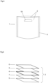
- FIG. 1 A perspective view of a film composite (1) according to the invention is shown.
- the film composite (1) formed from two film layers (2), has a sealed seam (3) on each of its three edges.
- the upper side is unsealed and open, creating a bag-like body.
- FIG. 2 A further embodiment of a film composite (1) according to the invention is shown.
- a film (2) is joined together by a sealed seam (3) on two opposite sides before folding, thus forming a tubular body.
- FIG. 3 An embodiment of a film composite (1) according to the invention with a penetration (19) of the film (2) at two locations is shown.
- the penetration (19) of the film (2) is arranged at opposite positions of the film (2) in the film composite (1), so that the holes (19) can be used as a gripping device.
- a hole (19) can be elongated with rounded corners, circular, or designed as a Euro hole.
- Various designs are also envisaged for the number and position of the hole(s).
- a film composite according to the invention can have no hole (19), exactly one hole (19), two holes (19), or more holes (19).
- the positioning of the holes (19) or the hole can be, for example, in an upper region centrally in a film composite (1) according to the invention or at any other location.
- a cellulose-based film (2) which can be used for a film composite (1) according to the invention.
- the core layer (4) consists of cellulose and, in one advantageous embodiment, makes up 89% to 93% of the total weight of the film (2). A proportion of 90% cellulose is particularly advantageous.
- the cellulose core (4) can be transparent and clear or pigmented.
- the film (2) also has two resin layers (5).
- the resin layers (5) are transparent and, due to their thermoplastic properties, facilitate a heat-sealing process for joining films (2). Furthermore, the sealing of the cellulose core (4) by the resin layers (5) facilitates the printing of corresponding films (2).
- a metal layer (7) can be vapor-deposited onto the cellulose core (4) between the cellulose core (4) and at least one resin layer (5).
- the film (2) can be printed on at least one side, creating at least one further layer (6) of printing ink.
- Further components of the film (2) are water in a weight proportion of preferably 4% to 6%, particularly preferably 4.5%, and glycerin in a weight proportion of 4% to 6%, particularly preferably 5%, as well as a coating in a weight proportion of approximately 0.5% of the film.
- the glycerin can be used as a plasticizer.
- the composition of the film varies within a certain range depending on the film thickness.
- the film (2) has a thickness of preferably 19 ⁇ m to 45 ⁇ m.
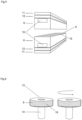
- Fig. 5 shows a perspective view of a welding device in the form of a pair of welding bars.
- the welding bars (8) are cuboid-shaped and each accommodates a heating element (10) in a groove.
- a pair of welding bars can, for example, consist of two welding bars (8) made of a non-adherent metallic material, such as aluminum, or of one welding bar (8) made of a non-adherent metallic material and one welding bar (8) made of a non-adherent plastic, such as silicone.
- the surfaces (9) of the welding device facing a film (2) to be welded have a structure (15) that enables the embossing of a sealing seam (3).
- a shock absorber (12) is attached between the fastening device (11) on a heat-sealing machine and a welding bar (8).
- FIG. 6 An alternative embodiment of a pair of welding devices is shown.
- This pair is designed as a pair of welding wheels (13) which, in a heat-sealing process, perform a counter-rotating movement around an axis (14) centrally connected to a welding wheel (13) and having an integrated heating element (10).
- the surfaces (9) of the welding wheels (13) have an embossed structure (15).
- At least one of the welding bars (8) or one of the welding wheels (13) has an embossed structure (15) on its embossed surface (9).
- At least one welding device (8, 13) of the pair of welding devices is heated in pulsed or continuous operation via a heating element (10). This produces temperatures between 80°C and 200°C, which are required for fusing the thermoplastic layers (5) of the film layers (2).
- the sealing time, during which the film layers (2) are pressed together between the welding devices (8) under a contact pressure, is preferably between 0.1 s and 1 s.
- the contact pressure is preferably 5 N/cm 2 to 30 N/cm 2 .
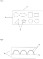
- Fig. 7 shows a plan view of the embossed surface (9) of a welding device (8).
- the embossed surface (9) on the side of the welding device (8) facing the film layers (2) to be sealed has differently shaped elevations and depressions, which in their entirety define the embossed pattern (15) of the welding device (8) and thus also of a sealing seam (3).
- the embossed pattern (15) is designed as a combination of various geometric shapes, such as, for example, a circle, an ellipse, a square, and a triangle.
- the structural size of the embossed surface (9) is adapted to the deformability of the material of the at least one foil (2).
- FIG. 8 A partial view of a section through a pair of welding devices, designed as welding bars (8), is shown.
- the embossed pattern (15) of the pair of welding bars (8) shown is semicircular and one-sided in the embossing direction, which means that the embossed structure (15) extends from a plane E1 essentially in one direction.
- FIG. 9 A partial cross-sectional view of an alternative embodiment of a pair of welding devices, configured as two welding bars (8), is shown.
- the embossed pattern (15) of the pair of welding bars (8) shown is semicircular and two-sided in the embossing direction, meaning that the embossed structure (15) extends from a plane E2 in two directions.
- Fig. 10 shows a top view of a partial view of five additional embossed patterns (15) in the area of the surface (9) of a welding device (8).
- Each of the individual embossed patterns (15) shown has a basic pattern that repeats regularly.
- the basic pattern can consist of one or more basic shapes, such as circles, rectangles, honeycombs, triangles, or trapezoids.
- FIG. 11 A section of a vertical section of a welding device is shown.
- the embossed structure (15) is designed in its basic form as a uniform distribution of hemispheres as recesses in the surface (9) of the welding device (8). Furthermore, the embossed structure (15) has further recesses in the surfaces of the hemispheres, which form a fractal structure.
- the hemispheres preferably have a diameter of approximately 4 mm, while the fractal structure size is in the order of magnitude of preferably 0.5 mm.
- the aim of the combination of a higher-level Structure with a fractal structure as embossed structure (15) is the creation of the largest possible surface in the connecting area (3) of the film layers (2).
- Fig. 12 shows a vertical section of a pair of welding bars (8).
- the embossed pattern (15) is irregularly formed in the illustrated embodiment and follows the principle of diversity.
- the embossed structure (15) has the greatest possible number of different lengths, radii, and angles in its cross-section.
- the diversity is achieved by combining various basic shapes and free forms to form a two-sided embossed pattern (15).
- a welding device (8, 13) can be provided with a one-sided or two-sided embossed pattern (15) according to the principle of diversity.
- Fig. 13 shows a top view of an embodiment of a welding bar (8) based on the principle of diversity.
- many different shapes as possible are arranged in the embossed surface (9) as an embossed structure (15).
- at least three different shapes are used, and particularly advantageously, at least ten different shapes are used.
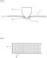
- FIG. 14 A perforation element (17) of one embodiment of a welding device is shown.
- the perforation element (17) protrudes in the base as a cylindrical body from the surface (9) of a welding device and tapers in the direction facing away from the welding device in the shape of a cone.
- two film layers (2) are shown, which are connected to one another in the region of the perforation element (17) by a weld seam (3). The connection is made by a perforation of the film layers (2) with the perforation element (17 of the welding device. and welding the resin layers (5).
- a thermoplastic bead (18) is formed by the perforation welding.
- FIG. 15 An exemplary representation of a sealing seam (3) produced by a heat sealing process with perforation elements (17) is shown in Fig. 15 shown as a top view. Arranged at regular intervals, thermoplastic beads (18) can be seen around the film openings.
Landscapes
- Engineering & Computer Science (AREA)
- Mechanical Engineering (AREA)
- Ceramic Engineering (AREA)
- Lining Or Joining Of Plastics Or The Like (AREA)
- Laminated Bodies (AREA)
Description
- Die Erfindung betrifft einen mehrlagigen Folienverbund sowie ein Verfahren zur Herstellung eines mehrlagigen Folienverbundes, insbesondere im Sinne eines Behältnisses aus auf Cellulose basierender Folie zur Lagerung oder zum Transport von Gegenständen oder Materialien.
- Beschichtete auf Cellulose basierende Folien werden aktuell durch ein Heißsiegelverfahren beispielsweise zu Beuteln oder ähnlichen Behältnissen zur Lagerung oder zum Transport von Gegenständen oder Materialien verarbeitet. In bekannten Heißsiegelverfahren werden mindestens zwei gegenüberliegende Lagen mindestens einer Folie in einem Bereich unter der Einwirkung von Temperatur, Druck und Zeit miteinander verbunden. Eine im Verbindungsbereich vollflächig aufgebrachte Harzschicht verschmilzt dabei die Folienlagen miteinander. In industriellem Umfeld werden für das Heißsiegelverfahren in der Regel Schweißbalken oder Schweißräder eingesetzt, die unter einem Druck gegeneinandergepresst werden und die zwischenliegenden Folienlagen in diesem Bereich verbinden. Die entstandene Verbindung wird als Schweiß- oder Siegelnaht bezeichnet.
- Aus der
WO 9323310 WO 9316931 - Weitere Vorrichtungen zur Herstellung von Folienverbunden unter Verwendung von Heißsiegelverfahren werden in der
US 4997504 , derWO 2007046974 , derDE 10 20 10 093 089 sowie derWO 2010055516 beschrieben. - Ein Problem, das bei den mithilfe bekannter Vorrichtungen und Verfahren hergestellten Schweißnähten zur Verbindung cellulosebasierter Folien auftritt, ist eine geringe mechanische Stabilität und Belastbarkeit der Schweißnähte.
- Eine Aufgabe der Erfindung ist es, einen Folienverbund auf Cellulosebasis mit einer erhöhten mechanischen Belastbarkeit der Schweißnaht zu realisieren.
- Diese Aufgabe wird erfindungsgemäß durch einen Folienverbund gemäß Patentanspruch 1 gelöst. Dadurch wird sowohl die Oberfläche im Verbindungsbereich vergrößert, als auch eine zusätzliche mechanische Verbindung durch ein Ineinandergreifen der Folienlagen erreicht.
- Eine weitere Aufgabe der Erfindung ist es, ein Verfahren zu definieren, durch das auf Cellulose basierende Folien mit einer höheren Festigkeit miteinander verbunden werden.
- Diese Aufgabe wird erfindungsgemäß durch ein Verfahren zur Herstellung eines mehrlagigen Folienverbundes aus mindestens einer cellulosebasierten Folie gemäß Patentanspruch 8 gelöst.
- Im Folgenden wird der erfindungsgemäße Folienverbund in beispielhafter Ausführungsform erläutert. Es zeigt:
- Fig. 1
- eine perspektivische Ansicht eines erfindungsgemäßen Folienverbundes mit drei Schweißnähten,
- Fig. 2
- eine perspektivische Darstellung eines erfindungsgemäßen Folienverbundes mit einer Schweißnaht,
- Fig. 3
- eine perspektivische Ansicht eines erfindungsgemäßen Folienverbundes mit Griffloch,
- Fig. 4
- eine perspektivische Ansicht einer auf Cellulose basierenden Folie im Schichtaufbau,
- Fig. 5
- eine perspektivische Ansicht einer Schweißvorrichtung zur Verbindung cellulosebasierter Folien,
- Fig. 6
- eine perspektivische Ansicht einer alternativen Ausführungsform einer Schweißvorrichtung zur Verbindung cellulosebasierter Folien,
- Fig. 7
- eine Teilansicht eines Schweißbalkens,
- Fig. 8
- einen Querschnitt eines Schweißbalkens mit einseitiger Prägung,
- Fig. 9
- einen Querschnitt eines Schweißbalkens mit zweiseitiger Prägung,
- Fig. 10
- fünf Teilansichten verschiedener Schweißbalken,
- Fig. 11
- einen Querschnitt durch einen Schweißbalken mit zusätzlicher fraktaler Struktur,
- Fig. 12
- einen Querschnitt durch ein Schweißbalkenpaar nach dem Prinzip der Verschiedenartigkeit,
- Fig. 13
- eine Draufsicht auf einen Schweißbalken nach dem Prinzip der Verschiedenartigkeit,
- Fig. 14
- einen Schnitt durch ein Perforationswerkzeug als Element eines Schweißbalkens und
- Fig. 15
- eine Ansicht einer Heißsiegelnaht einer auf Cellulose basierten Folie.
- In
Fig. 1 ist ein erfindungsgemäßer Folienverbund (1) in einer perspektivischen Ansicht dargestellt. Der aus zwei Folienlagen (2) ausgebildete Folienverbund (1) weist an drei seiner Ränder jeweils eine Siegelnaht (3) auf. Die obere Seite ist nicht versiegelt und geöffnet, sodass ein beutelartiger Körper entsteht. - In
Fig. 2 ist eine weitere Ausführungsform eines erfindungsgemäßen Folienverbunds (1) dargestellt. Eine Folie (2) ist dabei an zwei vor dem Umschlagen gegenüberliegenden Seiten durch eine Siegelnaht (3) miteinander verbunden, sodass ein schlauchartiger Körper entsteht. - In
Fig. 3 ist eine Ausführungsform eines erfindungsgemäßen Folienverbunds (1) mit einer Durchdringung (19) der Folie (2) an zwei Stellen dargestellt. Die Durchdringung (19) der Folie (2) ist an gegenüberliegenden Positionen der Folie (2) im Folienverbund (1) angeordnet, sodass die Löcher (19) als Griffvorrichtung nutzbar sind. - Es ist bei der Form des Loches (19) oder der Löcher, das bzw. die in einem erfindungsgemäßen Folienverbund (1) angeordnet sein können an verschiedene Ausbildungsformen gedacht. Beispielsweise kann ein Loch (19) länglich mit abgerundeten Ecken, kreisrund oder als Euroloch ausgebildet sein. Auch ist bei der Anzahl und der Position des bzw. der Löcher an verschiedene Ausführungsformen gedacht. So kann ein erfindungsgemäßer Folienverbund in vorteilhaften Ausführungsformen kein Loch (19), genau ein Loch (19), zwei Löcher (19) oder mehr Löcher (19) aufweisen. Die Positionierung der Löcher (19) bzw. des Loches kann beispielsweise in einem oberen Bereich mittig in einem erfindungsgemäßen Folienverbund (1) oder an beliebigen anderen Orten erfolgen.
- In
Fig. 4 ist ein beispielhafter Schichtaufbau einer auf Cellulose basierenden Folie (2) dargestellt, die für einen erfindungsgemäßen Folienverbund (1) genutzt werden kann. Die Kernschicht (4) besteht aus Cellulose und macht in einer vorteilhaften Ausführungsform 89 % bis 93 % des Gesamtgewichtes der Folie (2) aus. Besonders vorteilhaft ist ein Anteil von 90 % Cellulose. Der Cellulosekern (4) kann transparent und klar oder pigmentiert ausgebildet sein. Zusätzlich verfügt die Folie (2) über zwei Harzschichten (5). Die Harzschichten (5) sind transparent und begünstigen durch ihre thermoplastischen Eigenschaften ein Heißsiegelverfahren zur Verbindung von Folien (2). Zudem begünstigt die Versiegelung des Cellulosekerns (4) durch die Harzschichten (5) das Bedrucken entsprechender Folien (2). Zwischen dem Cellulosekern (4) und mindestens einer Harzschicht (5) kann eine Metallschicht (7) auf den Cellulosekern (4) aufgedampft sein. Die Folie (2) kann mindestens einseitig bedruckt sein, wodurch mindestens eine weitere Schicht (6) aus Druckfarbe entsteht. Weitere Bestandteile der Folie (2) sind Wasser mit einem Gewichtsanteil von bevorzugt 4 % bis 6 %, insbesondere bevorzugt 4,5 %, und Glycerin mit einem Anteil von 4 % bis 6 %, besonders bevorzugt von 5 %, sowie eine Beschichtung mit einem Gewichtsanteil von etwa 0,5 % der Folie. Das Glycerin kann als Weichmacher genutzt werden. Die Zusammensetzung der Folie variiert mit der Stärke der Folie in einem gewissen Bereich. Die Folie (2) hat eine Stärke von bevorzugt 19 µm bis 45 µm. -
Fig. 5 zeigt eine perspektivische Ansicht einer Schweißvorrichtung in Form eines Schweißbalkenpaares. Die Schweißbalken (8) sind quaderförmig ausgebildet und nehmen in einer Nut jeweils ein Heizelement (10) auf. Ein Schweißbalkenpaar kann sich beispielsweise aus zwei Schweißbalken (8) aus einem nicht anhaftenden metallischen Werkstoff, wie zum Beispiel Aluminium, oder aus einem Schweißbalken (8) aus einem nicht anhaftenden metallischen Werkstoff und einem Schweißbalken (8) aus einem nicht anhaftenden Kunststoff, wie zum Beispiel Silikon, zusammensetzen. Die einer zu verschweißenden Folie (2) zugewandte Oberflächen (9) der Schweißvorrichtung weisen eine Struktur (15) auf, die eine Prägung einer Sieglenaht (3) ermöglicht. Zwischen der Befestigungseinrichtung (11) an einer Heißsiegelmaschine und einem Schweißbalken (8) ist ein Stoßdämpfer (12) angebracht. - In
Fig. 6 ist eine alternative Ausführungsform eines Schweißvorrichtungspaares dargestellt. Dieses ist als ein Paar von Schweißrädern (13) ausgebildet, die in einem Heißsiegelverfahren eine gegenläufige Rotationsbewegung um eine jeweils zentral mit einem Schweißrad (13) verbundene Achse (14) mit einem integrierten Heizelement (10) durchführen. Die Oberflächen (9) der Schweißräder (13) weisen eine Prägestruktur (15) auf. - In alternativen Ausführungsformen von Schweißvorrichtungspaaren weist mindestens einer der Schweißbalken (8) bzw. eines der Schweißräder (13) auf seiner Prägeoberfläche (9) eine Prägestruktur (15) auf.
- Im erfindungsgemäßen Heißsiegelverfahren wird mindestens eine Schweißvorrichtung (8, 13) des Schweißvorrichtungspaares über ein Heizelement (10) im Impuls- oder Dauerbetrieb beheizt. Dabei entstehen Temperaturen zwischen 80 °C und 200 °C, die für das Verschmelzen der thermoplastischen Schichten (5) der Folienlagen (2) erforderlich sind. Die Siegelzeit, in der die Folienlagen (2) zwischen den Schweißvorrichtungen (8) unter einem Anpressdruck zusammengepresst werden, beträgt vorzugsweise zwischen 0,1 s und 1s. Der Anpressdruck beträgt bevorzugt 5 N/cm2 bis 30 N/cm2. Mit dem erfindungsgemäßen Verfahren zur Heißsiegelverbindung von Folien (2) werden Siegelnahtbreiten von bevorzugt 4 mm bis 20 mm erreicht. Die mithilfe der mindestens einen Prägeoberfläche (9) des Schweißvorrichtungspaares durch die Lagen des Folienverbundes hindurch geprägte Struktur im Bereich einer Schweißnaht, sorgt für eine zusätzliche Verbindung der Folienlagen (2) durch einen Formschluss zwischen den verbundenen Lagen (2).
-
Fig. 7 zeigt eine Draufsicht auf die Prägeoberfläche (9) einer Schweißvorrichtung (8). Die Prägeoberfläche (9) auf der den zu versiegelnden Folienlagen (2) zugewandten Seite der Schweißvorrichtung (8) weist verschieden geformte Erhöhungen und Vertiefungen auf, die in ihrer Gesamtheit das Prägemuster (15) der Schweißvorrichtung (8) und damit auch einer Siegelnaht (3) definieren. Erfindungsgemäß ist das Prägemuster (15) als eine Kombination verschiedener geometrischer Formen wie beispielsweise einem Kreis, einer Ellipse, einem Quadrat und einem Dreieck ausgebildet. Die Strukturgröße der Prägeoberfläche (9) ist an die Verformbarkeit des Materials der mindestens einen Folie (2) angepasst. - In
Fig. 8 ist eine Teilansicht eines Schnittes durch ein Schweißvorrichtungspaar, ausgebildet als Schweißbalken (8), dargestellt. Das Prägemuster (15) des gezeigten Schweißbalkenpaares (8) ist in Prägerichtung halbkreisartig und einseitig ausgebildet, was bedeutet, dass sich die Prägestruktur (15) aus einer Ebene E1 im Wesentlichen in eine Richtung erstreckt. - In
Fig. 9 ist eine Teilansicht eines Schnittes durch eine alternative Ausführungsform eines Schweißvorrichtungspaares, ausgebildet als zwei Schweißbalken (8), dargestellt. Das Prägemuster (15) des gezeigten Schweißbalkenpaares (8) ist in Prägerichtung halbkreisartig und zweiseitig ausgebildet, was bedeutet, dass sich die Prägestruktur (15) aus einer Ebene E2 in zwei Richtungen erstreckt. -
Fig. 10 zeigt eine Draufsicht auf eine Teilansicht von fünf weiteren Prägemustern (15) im Bereich der Oberfläche (9) einer Schweißvorrichtung (8). Jedes der dargestellten individuellen Prägemuster (15) besitzt ein Grundmuster, das sich regelmäßig wiederholt. Das Grundmuster kann aus einer oder mehreren Grundformen, wie beispielsweise Kreisen, Rechtecken, Waben, Dreiecken oder Trapezen, bestehen. - In
Fig. 11 ist ein Ausschnitt eines vertikalen Schnitts einer Schweißvorrichtung dargestellt. Die Prägestruktur (15) ist in ihrer Grundform als eine gleichmäßige Verteilung von Halbkugeln als Aussparungen in der Oberfläche (9) der Schweißvorrichtung (8) ausgebildet. Weiterhin weist die Prägestruktur (15) in den Oberflächen der Halbkugeln weitere Aussparungen auf, die ein fraktale Struktur bilden. Die Halbkugeln weisen bevorzugt einen Durchmesser vom etwa 4 mm auf, während die fraktale Strukturgröße in einer Größenordnung von bevorzugt 0,5 mm liegt. Ziel der Kombination einer übergeordneten Struktur mit einer fraktalen Struktur als Prägestruktur (15) ist die Erzeugung einer möglichst großen Oberfläche im Verbindungsbereich (3) der Folienlagen (2). -
Fig. 12 zeigt einen vertikalen Schnitt eines Schweißbalkenpaares (8). Das Prägemuster (15) ist in der gezeigten Ausführungsform ungleichmäßig ausgebildet und folgt dem Prinzip der Verschiedenartigkeit. Die Prägestruktur (15) weist in ihrem Querschnitt dabei eine möglichst hohe Anzahl verschiedener Strecken, Radien und Winkel auf. Die Verschiedenartigkeit wird in der dargestellten Ausführungsform durch die Kombination verschiedener Grundformen und freier Formen zu einem zweiseitig ausgebildeten Prägemuster (15) erreicht. - Eine Schweißvorrichtung (8, 13) kann mit einem einseitig oder einem zweiseitig ausgebildeten Prägemuster (15) nach dem Prinzip der Verschiedenartigkeit versehen sein.
-
Fig. 13 stellt eine Draufsicht auf eine Ausführungsform eines Schweißbalkens (8) nach dem Prinzip der Verschiedenartigkeit dar. In der Prägeoberfläche (9) sind möglichst viele verschiedene Formen als Prägestruktur (15) angeordnet. Vorteilhaft werden mindestens drei verschiedene Formen, besonders vorteilhaft mindestens zehn verschiedene Formen, genutzt. - In
Fig. 14 ist ein Perforationselement (17) einer Ausführungsform einer Schweißvorrichtung dargestellt. Das Perforationselement (17) ragt in der Basis als zylindrischer Körper aus der Oberfläche (9) einer Schweißvorrichtung heraus und verjüngt sich in von der Schweißvorrichtung abgewandter Richtung in Form eines Kegels. Weiterhin ist sind zwei Folienlagen (2) dargestellt, die im Bereich des Perforationselementes (17) durch eine Schweißnaht (3) miteinander verbunden sind. Die Verbindung ist durch eine Perforation der Folienlagen (2) mit dem Perforationselement (17) der Schweißvorrichtung und einem Verschweißen der Harzschichten (5) realisiert. Auf der dem Perforationselement (17) abgewandten Seite des Folienverbundes (1) ist durch die Perforationsverschweißung ein thermoplastischer Wulst (18) ausgebildet. - In einem erfindungsgemäßen Heißsiegelverfahren zur Verbindung von cellulosebasierten Folienlagen (2) unter Verwendung einer Schweißvorrichtung mit Perforationselementen (17) werden die Folienlagen (2) unter der Einwirkung von Hitze, Druck und Zeit verformt und in den Bereichen der Perforationselemente (17) durchdrungen. Je nach Form der Perforationselemente (17) kann diese Durchdringung kreisrund, für ein als Kreiskegel ausgebildetes Perforationselement (17), oder beispielsweise eckig, für ein als Pyramide ausgebildetes Perforationselement (17), sein. Das thermoplastische Material (5) wird durch die Hitzeeinwirkung geschmolzen, durch die Folienöffnung gedrückt, wirft sich an den Rändern der Folienöffnung in der Form eines Wulstes (18) auf und erkaltet nachdem sich die thermoplastischen Schichten (5) der Folienlagen (2) verschmolzen haben.
- Eine beispielhafte Darstellung einer durch ein Heißsiegelverfahren mit Perforationselementen (17) erzeugten Siegelnaht (3) ist in
Fig. 15 als Draufsicht dargestellt. In regelmäßigen Abständen angeordnet, sind thermoplastischen Wulste (18) um die Folienöffnungen herum zu erkennen. - Dadurch, dass im Bereich einer Heißsiegelmaschine im Vergleich zu einer herkömmlichen Heißsiegelvorrichtung für Folien aus thermoplastischem Kunststoff im Wesentlichen nur die Schweißvorrichtungen ausgetauscht werden müssen, sind vorhandene Maschinen einfach und kostengünstig derart umrüstbar, dass mithilfe der Schweißvorrichtungen das erfindungsgemäße Heißsiegelverfahren zur Herstellung eines erfindungsgemäßen Folienverbundes (1) umsetzbar ist.
Claims (11)
- Folienverbund (1) aus mindestens zwei Lagen mindestens einer cellulosebasierten Folie (2), wobei die Verbindung durch mindestens eine Schweiß- bzw. Siegelnaht (3) realisiert ist, in der sich dreidimensional geprägte Strukturen mindestens bereichsweise durch die mindestens zwei verbundenen Lagen (2) erstrecken, wobei die mindestens eine Folie (2) aus mehreren Schichten aufgebaut ist und wobei die mindestens eine Folie (2) mindestens aus einer Kernschicht (4) aus überwiegend Cellulose und zwei thermoplastischen Schichten (5) besteht, dadurch gekennzeichnet, dass die geprägten Strukturen im Bereich der Siegelnaht (3) ein Prägemuster (15) bilden, das als eine Kombination verschiedener geometrischer Formen ausgebildet ist.
- Folienverbund nach Anspruch 1, dadurch gekennzeichnet, dass die thermoplastischen Schichten (5) als Harzschichten realisiert sind.
- Folienverbund (1) nach mindestens einem der vorstehenden Ansprüche, dadurch gekennzeichnet, dass die geprägten Strukturen im Bereich der Siegelnaht (3) ein Prägemuster (15) bilden, das als ein sich wiederholendes Muster, als ein Muster mit mindestens drei verschiedenen Elementen, bevorzugt mit mindestens zehn verschiedenen Elementen, oder als eine Perforation ausgebildet ist.
- Folienverbund nach Anspruch 3, dadurch gekennzeichnet, dass das Prägemuster (15) ein Grundmuster besitzt, das sich regelmäßig wiederholt.
- Folienverbund nach einem der Ansprüche 3 und 4, dadurch gekennzeichnet, dass das Prägemuster (15) als ein zweiseitiges Prägemuster (15) ausgebildet ist.
- Folienverbund nach Anspruch 3, dadurch gekennzeichnet, dass das Prägemuster (15) Perforationen mit thermoplastischem Wulst (18) aufweist.
- Folienverbund (1) nach mindestens einem der vorstehenden Ansprüche, dadurch gekennzeichnet, dass der Folienverbund (1) als ein Behältnis zum Transport oder zur Lagerung von Materialien oder Gegenständen ausgebildet ist.
- Verfahren zur Herstellung eines mehrlagigen Folienverbundes (1) aus mindestens einer cellulosebasierten Folie (2), dadurch gekennzeichnet, dass ein mehrlagiger Folienverbund gemäß einem der Ansprüche 1 bis 7 hergestellt wird, dass es sich um ein Heißsiegelverfahren handelt und dass eine Schweißvorrichtung mit dreidimensional ausgebildeter Prägeoberfläche (9) verwendet wird.
- Verfahren nach Anspruch 8, dadurch gekennzeichnet, dass eine Siegeltemperatur zwischen 80°C und 200°C genutzt wird.
- Verfahren nach mindestens einem der Ansprüche 8 und 9, dadurch gekennzeichnet, dass die Siegelzeit zwischen 0,1 s und 1 s beträgt.
- Verfahren nach mindestens einem der Ansprüche 8 bis 10, dadurch gekennzeichnet, dass ein Anpressdruck zwischen 5 N/cm2 und 30 N/cm2 genutzt wird.
Applications Claiming Priority (1)
| Application Number | Priority Date | Filing Date | Title |
|---|---|---|---|
| DE102017009889.1A DE102017009889A1 (de) | 2017-10-19 | 2017-10-19 | Mehrlagiger Folienverbund sowie Verfahren und Vorrichtung zur Herstellung eines mehrlagigen Folienverbundes |
Publications (4)
| Publication Number | Publication Date |
|---|---|
| EP3473437A2 EP3473437A2 (de) | 2019-04-24 |
| EP3473437A3 EP3473437A3 (de) | 2019-07-31 |
| EP3473437B1 EP3473437B1 (de) | 2022-10-12 |
| EP3473437B2 true EP3473437B2 (de) | 2025-04-30 |
Family
ID=63683089
Family Applications (1)
| Application Number | Title | Priority Date | Filing Date |
|---|---|---|---|
| EP18196314.1A Active EP3473437B2 (de) | 2017-10-19 | 2018-09-24 | Mehrlagiger folienverbund sowie verfahren zur herstellung eines mehrlagigen folienverbundes |
Country Status (5)
| Country | Link |
|---|---|
| EP (1) | EP3473437B2 (de) |
| DE (1) | DE102017009889A1 (de) |
| DK (1) | DK3473437T3 (de) |
| ES (1) | ES2935344T3 (de) |
| PL (1) | PL3473437T3 (de) |
Families Citing this family (1)
| Publication number | Priority date | Publication date | Assignee | Title |
|---|---|---|---|---|
| DE102017009889A1 (de) | 2017-10-19 | 2019-04-25 | Superseven Gmbh | Mehrlagiger Folienverbund sowie Verfahren und Vorrichtung zur Herstellung eines mehrlagigen Folienverbundes |
Citations (1)
| Publication number | Priority date | Publication date | Assignee | Title |
|---|---|---|---|---|
| DE69309265T2 (de) † | 1992-05-15 | 1997-10-30 | Int Paper Co | Flexibler behälter mit nicht aneinanderhaftenden innenoberflächen |
Family Cites Families (18)
| Publication number | Priority date | Publication date | Assignee | Title |
|---|---|---|---|---|
| FR1384846A (fr) | 1963-11-29 | 1965-01-08 | Cellophane Sa | Procédé perfectionné d'application d'enduits imperméables, scellables à chaud, sur des pellicules hydrophiles |
| US3534901A (en) * | 1968-12-09 | 1970-10-20 | Dow Chemical Co | Bag construction |
| US4151916A (en) * | 1970-07-15 | 1979-05-01 | Ab Anero | Packaging materials |
| US4044528A (en) * | 1974-09-03 | 1977-08-30 | American Brands, Inc. | Method and apparatus for forming sealed packages |
| US4997504A (en) * | 1978-10-10 | 1991-03-05 | Wood James R | Method and apparatus for high speed pouch and bag making |
| DE3343635A1 (de) | 1983-12-02 | 1985-06-13 | Hoechst Ag, 6230 Frankfurt | Folie aus faserverstaerkter regenerierter cellulose mit gasundurchlaessiger schicht zur herstellung von schlauchhuellen |
| CA2027640A1 (en) * | 1989-10-16 | 1991-04-17 | Peter Raphael Hudetz | Packaging bag for insertion into a publication |
| WO1993016931A1 (en) * | 1992-02-25 | 1993-09-02 | Simple Packaging Solutions, Inc. | Apparatus and method for making a reclosable bag |
| JP3678361B2 (ja) * | 2001-06-08 | 2005-08-03 | 大日本印刷株式会社 | ガスバリアフィルム |
| DE10311125A1 (de) | 2002-03-30 | 2003-11-27 | Henkel Kgaa | Mehrschichten-Folien |
| ITTO20020470A1 (it) | 2002-05-31 | 2003-12-01 | Tetra Laval Holdings E Finance | Ganascia di formatura per la realizzazione di una successione di confezioni sigillate a partire da un tubo di materiale di confezionamento i |
| DE202005020833U1 (de) | 2005-06-30 | 2006-11-02 | Huhtamaki Ronsberg, Zweigniederlassung Der Huhtamaki Deutschland Gmbh & Co. Kg | Behälter, insbesondere Verpackungsbehälter, mit Siegelung |
| US20070093157A1 (en) | 2005-10-20 | 2007-04-26 | Kimberly-Clark Worldwide, Inc. | High speed, pressure bonded, thin sheet laminate |
| JP4490493B2 (ja) * | 2008-07-11 | 2010-06-23 | 株式会社悠心 | 逆止機能ノズルを備えるフレキシブル包装袋 |
| WO2010055516A1 (en) * | 2008-11-14 | 2010-05-20 | L.C.S. Tech Ltd | System and method for configurationally heat soldering plastic bags |
| DE102010039089B4 (de) * | 2010-08-09 | 2013-06-27 | Widmann Maschinen GmbH & Co. KG | Schweißvorrichtung |
| DE102017218176A1 (de) | 2017-10-11 | 2019-04-11 | Huhtamaki Flexible Packaging Germany Gmbh & Co. Kg | Verwendung einer Zellglasfolie zur Verpackung von pastösen, wasserlöslichen Lebensmitteln in geometrisch bestimmter Gestalt |
| DE102017009889A1 (de) | 2017-10-19 | 2019-04-25 | Superseven Gmbh | Mehrlagiger Folienverbund sowie Verfahren und Vorrichtung zur Herstellung eines mehrlagigen Folienverbundes |
-
2017
- 2017-10-19 DE DE102017009889.1A patent/DE102017009889A1/de active Pending
-
2018
- 2018-09-24 EP EP18196314.1A patent/EP3473437B2/de active Active
- 2018-09-24 PL PL18196314.1T patent/PL3473437T3/pl unknown
- 2018-09-24 DK DK18196314.1T patent/DK3473437T3/da active
- 2018-09-24 ES ES18196314T patent/ES2935344T3/es active Active
Patent Citations (1)
| Publication number | Priority date | Publication date | Assignee | Title |
|---|---|---|---|---|
| DE69309265T2 (de) † | 1992-05-15 | 1997-10-30 | Int Paper Co | Flexibler behälter mit nicht aneinanderhaftenden innenoberflächen |
Also Published As
| Publication number | Publication date |
|---|---|
| EP3473437B1 (de) | 2022-10-12 |
| EP3473437A3 (de) | 2019-07-31 |
| DK3473437T3 (da) | 2023-01-09 |
| EP3473437A2 (de) | 2019-04-24 |
| PL3473437T3 (pl) | 2023-02-20 |
| ES2935344T3 (es) | 2023-03-06 |
| DE102017009889A1 (de) | 2019-04-25 |
Similar Documents
| Publication | Publication Date | Title |
|---|---|---|
| EP2845820B1 (de) | Seitenfaltenbeutel aus einem Kunststoffgewebeverbund | |
| EP3194681A1 (de) | Wabe, insbesondere verformbare wabe, für leichtbauteile, entsprechendes herstellungsverfahren und sandwichbauteil | |
| EP1492672B1 (de) | Vorrichtung und verfahren zur herstellung von verbundwerkstoffen | |
| DE102015005407A1 (de) | Rührreibschweißen von Thermoplasten | |
| DE102014201296A1 (de) | Verfahren zum Fügen von faserverstärktem Kunststoffmaterial | |
| DE3445524A1 (de) | Verfahren und vorrichtung zum verschweissen von kunststoffolien | |
| DE4114506A1 (de) | Luftkissenfolie, verfahren zu ihrer herstellung und vorrichtung zur durchfuehrung des verfahrens | |
| EP3473437B1 (de) | Mehrlagiger folienverbund sowie verfahren zur herstellung eines mehrlagigen folienverbundes | |
| EP2504150A1 (de) | Verfahren zum verschliessen eines sackkörpers | |
| EP1535723A2 (de) | Vorrichtung zum Verschweissen von mehrlagigen Laminaten | |
| EP2720850B1 (de) | Verfahren zum herstellen von rohrkörpern für verpackungstuben sowie verpackungstube mit rohrkörper | |
| DE2656804C3 (de) | Verfahren zum T- oder Stumpfschweißen von Schichtkörpern mit einer Innenschicht aus thermoplastischem Schaumkunststoff | |
| DE102010021703A1 (de) | Verpackungseinheit | |
| DE102016005379A1 (de) | Hybrider, textilverstärker Multi-Material-Verbundwerkstoff und Verfahren zu seiner Herstellung | |
| WO2011050380A1 (de) | VERFAHREN ZUM VERSCHLIEßEN EINES SACKKÖRPERS | |
| DE102012003969B4 (de) | Aufblasbarer Körper | |
| DE2165620C3 (de) | Vorrichtung zum flächenmässigen Ultraschallverschweissen kunststoffhaltiger oder kunststoffbeschichteter Folien | |
| WO2015149090A1 (de) | Verfahren und vorrichtungzur herstellung von säcken aus einem gewebeschlauch | |
| DE102010031362A1 (de) | Verbundfolie, Verfahren zur Herstellung einer Verbundfolie, eines aus wenigstens einer Verbundfolie bestehenden Folienverbundes sowie Vorrichtung zur Herstellung einer Verbundfolie | |
| EP2707132B1 (de) | Verfahren zur herstellung eines rohrs oder rohrhalbzeugs und rohr oder rohrhalbzeug für den chemischen apparatebau | |
| EP3835035A1 (de) | Verfahren zum verbinden von werkstücken und zusammengesetzter gegenstand | |
| DE3741692C2 (de) | Verfahren zur Herstellung eines Verbundteiles sowie Verbundteil | |
| DE20107626U1 (de) | Mit Fluorpolymeren verbundene Polytetrafluorethylen-Formkörper | |
| DE202017104240U1 (de) | Vorstufe für einen keramischen Filter und keramisches Filter | |
| DE19813387C2 (de) | Verfahren zur Herstellung eines rohrförmigen Hohlkörpers aus Polytetrafluorethylen oder aus einem PTFE-Recyclat |
Legal Events
| Date | Code | Title | Description |
|---|---|---|---|
| PUAI | Public reference made under article 153(3) epc to a published international application that has entered the european phase |
Free format text: ORIGINAL CODE: 0009012 |
|
| STAA | Information on the status of an ep patent application or granted ep patent |
Free format text: STATUS: THE APPLICATION HAS BEEN PUBLISHED |
|
| AK | Designated contracting states |
Kind code of ref document: A2 Designated state(s): AL AT BE BG CH CY CZ DE DK EE ES FI FR GB GR HR HU IE IS IT LI LT LU LV MC MK MT NL NO PL PT RO RS SE SI SK SM TR |
|
| AX | Request for extension of the european patent |
Extension state: BA ME |
|
| PUAL | Search report despatched |
Free format text: ORIGINAL CODE: 0009013 |
|
| AK | Designated contracting states |
Kind code of ref document: A3 Designated state(s): AL AT BE BG CH CY CZ DE DK EE ES FI FR GB GR HR HU IE IS IT LI LT LU LV MC MK MT NL NO PL PT RO RS SE SI SK SM TR |
|
| AX | Request for extension of the european patent |
Extension state: BA ME |
|
| RIC1 | Information provided on ipc code assigned before grant |
Ipc: B32B 38/06 20060101ALI20190625BHEP Ipc: B32B 23/08 20060101AFI20190625BHEP Ipc: B29C 65/00 20060101ALI20190625BHEP |
|
| STAA | Information on the status of an ep patent application or granted ep patent |
Free format text: STATUS: REQUEST FOR EXAMINATION WAS MADE |
|
| 17P | Request for examination filed |
Effective date: 20200130 |
|
| STAA | Information on the status of an ep patent application or granted ep patent |
Free format text: STATUS: EXAMINATION IS IN PROGRESS |
|
| 17Q | First examination report despatched |
Effective date: 20201221 |
|
| REG | Reference to a national code |
Ref country code: DE Ref legal event code: R079 Ref document number: 502018010813 Country of ref document: DE Free format text: PREVIOUS MAIN CLASS: B32B0023080000 Ipc: B29C0065180000 |
|
| RIC1 | Information provided on ipc code assigned before grant |
Ipc: B65D 75/30 20060101ALI20220516BHEP Ipc: B29C 65/18 20060101AFI20220516BHEP |
|
| GRAP | Despatch of communication of intention to grant a patent |
Free format text: ORIGINAL CODE: EPIDOSNIGR1 |
|
| STAA | Information on the status of an ep patent application or granted ep patent |
Free format text: STATUS: GRANT OF PATENT IS INTENDED |
|
| INTG | Intention to grant announced |
Effective date: 20220627 |
|
| GRAS | Grant fee paid |
Free format text: ORIGINAL CODE: EPIDOSNIGR3 |
|
| GRAA | (expected) grant |
Free format text: ORIGINAL CODE: 0009210 |
|
| STAA | Information on the status of an ep patent application or granted ep patent |
Free format text: STATUS: THE PATENT HAS BEEN GRANTED |
|
| AK | Designated contracting states |
Kind code of ref document: B1 Designated state(s): AL AT BE BG CH CY CZ DE DK EE ES FI FR GB GR HR HU IE IS IT LI LT LU LV MC MK MT NL NO PL PT RO RS SE SI SK SM TR |
|
| REG | Reference to a national code |
Ref country code: GB Ref legal event code: FG4D Free format text: NOT ENGLISH |
|
| REG | Reference to a national code |
Ref country code: CH Ref legal event code: EP |
|
| REG | Reference to a national code |
Ref country code: DE Ref legal event code: R096 Ref document number: 502018010813 Country of ref document: DE |
|
| REG | Reference to a national code |
Ref country code: IE Ref legal event code: FG4D Free format text: LANGUAGE OF EP DOCUMENT: GERMAN |
|
| REG | Reference to a national code |
Ref country code: AT Ref legal event code: REF Ref document number: 1523902 Country of ref document: AT Kind code of ref document: T Effective date: 20221115 |
|
| REG | Reference to a national code |
Ref country code: NL Ref legal event code: FP |
|
| REG | Reference to a national code |
Ref country code: DK Ref legal event code: T3 Effective date: 20230106 |
|
| REG | Reference to a national code |
Ref country code: SE Ref legal event code: TRGR |
|
| REG | Reference to a national code |
Ref country code: LT Ref legal event code: MG9D |
|
| REG | Reference to a national code |
Ref country code: ES Ref legal event code: FG2A Ref document number: 2935344 Country of ref document: ES Kind code of ref document: T3 Effective date: 20230306 |
|
| PG25 | Lapsed in a contracting state [announced via postgrant information from national office to epo] |
Ref country code: PT Free format text: LAPSE BECAUSE OF FAILURE TO SUBMIT A TRANSLATION OF THE DESCRIPTION OR TO PAY THE FEE WITHIN THE PRESCRIBED TIME-LIMIT Effective date: 20230213 Ref country code: NO Free format text: LAPSE BECAUSE OF FAILURE TO SUBMIT A TRANSLATION OF THE DESCRIPTION OR TO PAY THE FEE WITHIN THE PRESCRIBED TIME-LIMIT Effective date: 20230112 Ref country code: LT Free format text: LAPSE BECAUSE OF FAILURE TO SUBMIT A TRANSLATION OF THE DESCRIPTION OR TO PAY THE FEE WITHIN THE PRESCRIBED TIME-LIMIT Effective date: 20221012 Ref country code: FI Free format text: LAPSE BECAUSE OF FAILURE TO SUBMIT A TRANSLATION OF THE DESCRIPTION OR TO PAY THE FEE WITHIN THE PRESCRIBED TIME-LIMIT Effective date: 20221012 |
|
| PG25 | Lapsed in a contracting state [announced via postgrant information from national office to epo] |
Ref country code: RS Free format text: LAPSE BECAUSE OF FAILURE TO SUBMIT A TRANSLATION OF THE DESCRIPTION OR TO PAY THE FEE WITHIN THE PRESCRIBED TIME-LIMIT Effective date: 20221012 Ref country code: LV Free format text: LAPSE BECAUSE OF FAILURE TO SUBMIT A TRANSLATION OF THE DESCRIPTION OR TO PAY THE FEE WITHIN THE PRESCRIBED TIME-LIMIT Effective date: 20221012 Ref country code: IS Free format text: LAPSE BECAUSE OF FAILURE TO SUBMIT A TRANSLATION OF THE DESCRIPTION OR TO PAY THE FEE WITHIN THE PRESCRIBED TIME-LIMIT Effective date: 20230212 Ref country code: HR Free format text: LAPSE BECAUSE OF FAILURE TO SUBMIT A TRANSLATION OF THE DESCRIPTION OR TO PAY THE FEE WITHIN THE PRESCRIBED TIME-LIMIT Effective date: 20221012 Ref country code: GR Free format text: LAPSE BECAUSE OF FAILURE TO SUBMIT A TRANSLATION OF THE DESCRIPTION OR TO PAY THE FEE WITHIN THE PRESCRIBED TIME-LIMIT Effective date: 20230113 |
|
| REG | Reference to a national code |
Ref country code: DE Ref legal event code: R026 Ref document number: 502018010813 Country of ref document: DE |
|
| PLBI | Opposition filed |
Free format text: ORIGINAL CODE: 0009260 |
|
| PLAX | Notice of opposition and request to file observation + time limit sent |
Free format text: ORIGINAL CODE: EPIDOSNOBS2 |
|
| PG25 | Lapsed in a contracting state [announced via postgrant information from national office to epo] |
Ref country code: SM Free format text: LAPSE BECAUSE OF FAILURE TO SUBMIT A TRANSLATION OF THE DESCRIPTION OR TO PAY THE FEE WITHIN THE PRESCRIBED TIME-LIMIT Effective date: 20221012 Ref country code: RO Free format text: LAPSE BECAUSE OF FAILURE TO SUBMIT A TRANSLATION OF THE DESCRIPTION OR TO PAY THE FEE WITHIN THE PRESCRIBED TIME-LIMIT Effective date: 20221012 Ref country code: EE Free format text: LAPSE BECAUSE OF FAILURE TO SUBMIT A TRANSLATION OF THE DESCRIPTION OR TO PAY THE FEE WITHIN THE PRESCRIBED TIME-LIMIT Effective date: 20221012 |
|
| 26 | Opposition filed |
Opponent name: TECHNIKUM LAUBHOLZ GMBH Effective date: 20230712 |
|
| PG25 | Lapsed in a contracting state [announced via postgrant information from national office to epo] |
Ref country code: SK Free format text: LAPSE BECAUSE OF FAILURE TO SUBMIT A TRANSLATION OF THE DESCRIPTION OR TO PAY THE FEE WITHIN THE PRESCRIBED TIME-LIMIT Effective date: 20221012 Ref country code: AL Free format text: LAPSE BECAUSE OF FAILURE TO SUBMIT A TRANSLATION OF THE DESCRIPTION OR TO PAY THE FEE WITHIN THE PRESCRIBED TIME-LIMIT Effective date: 20221012 |
|
| PG25 | Lapsed in a contracting state [announced via postgrant information from national office to epo] |
Ref country code: SI Free format text: LAPSE BECAUSE OF FAILURE TO SUBMIT A TRANSLATION OF THE DESCRIPTION OR TO PAY THE FEE WITHIN THE PRESCRIBED TIME-LIMIT Effective date: 20221012 |
|
| PLBB | Reply of patent proprietor to notice(s) of opposition received |
Free format text: ORIGINAL CODE: EPIDOSNOBS3 |
|
| RAP4 | Party data changed (patent owner data changed or rights of a patent transferred) |
Owner name: SUPERSEVEN GMBH |
|
| PG25 | Lapsed in a contracting state [announced via postgrant information from national office to epo] |
Ref country code: MC Free format text: LAPSE BECAUSE OF FAILURE TO SUBMIT A TRANSLATION OF THE DESCRIPTION OR TO PAY THE FEE WITHIN THE PRESCRIBED TIME-LIMIT Effective date: 20221012 |
|
| REG | Reference to a national code |
Ref country code: IE Ref legal event code: MM4A |
|
| PG25 | Lapsed in a contracting state [announced via postgrant information from national office to epo] |
Ref country code: IE Free format text: LAPSE BECAUSE OF NON-PAYMENT OF DUE FEES Effective date: 20230924 |
|
| PG25 | Lapsed in a contracting state [announced via postgrant information from national office to epo] |
Ref country code: IE Free format text: LAPSE BECAUSE OF NON-PAYMENT OF DUE FEES Effective date: 20230924 |
|
| PGFP | Annual fee paid to national office [announced via postgrant information from national office to epo] |
Ref country code: DK Payment date: 20240923 Year of fee payment: 7 |
|
| PGFP | Annual fee paid to national office [announced via postgrant information from national office to epo] |
Ref country code: NL Payment date: 20240918 Year of fee payment: 7 |
|
| PGFP | Annual fee paid to national office [announced via postgrant information from national office to epo] |
Ref country code: CZ Payment date: 20240913 Year of fee payment: 7 |
|
| PGFP | Annual fee paid to national office [announced via postgrant information from national office to epo] |
Ref country code: PL Payment date: 20240912 Year of fee payment: 7 |
|
| PGFP | Annual fee paid to national office [announced via postgrant information from national office to epo] |
Ref country code: SE Payment date: 20240919 Year of fee payment: 7 Ref country code: IT Payment date: 20240924 Year of fee payment: 7 |
|
| PG25 | Lapsed in a contracting state [announced via postgrant information from national office to epo] |
Ref country code: BG Free format text: LAPSE BECAUSE OF FAILURE TO SUBMIT A TRANSLATION OF THE DESCRIPTION OR TO PAY THE FEE WITHIN THE PRESCRIBED TIME-LIMIT Effective date: 20221012 |
|
| PG25 | Lapsed in a contracting state [announced via postgrant information from national office to epo] |
Ref country code: BG Free format text: LAPSE BECAUSE OF FAILURE TO SUBMIT A TRANSLATION OF THE DESCRIPTION OR TO PAY THE FEE WITHIN THE PRESCRIBED TIME-LIMIT Effective date: 20221012 |
|
| PGFP | Annual fee paid to national office [announced via postgrant information from national office to epo] |
Ref country code: ES Payment date: 20241028 Year of fee payment: 7 |
|
| PUAH | Patent maintained in amended form |
Free format text: ORIGINAL CODE: 0009272 |
|
| STAA | Information on the status of an ep patent application or granted ep patent |
Free format text: STATUS: PATENT MAINTAINED AS AMENDED |
|
| 27A | Patent maintained in amended form |
Effective date: 20250430 |
|
| AK | Designated contracting states |
Kind code of ref document: B2 Designated state(s): AL AT BE BG CH CY CZ DE DK EE ES FI FR GB GR HR HU IE IS IT LI LT LU LV MC MK MT NL NO PL PT RO RS SE SI SK SM TR |
|
| REG | Reference to a national code |
Ref country code: DE Ref legal event code: R102 Ref document number: 502018010813 Country of ref document: DE |
|
| PG25 | Lapsed in a contracting state [announced via postgrant information from national office to epo] |
Ref country code: CY Free format text: LAPSE BECAUSE OF FAILURE TO SUBMIT A TRANSLATION OF THE DESCRIPTION OR TO PAY THE FEE WITHIN THE PRESCRIBED TIME-LIMIT; INVALID AB INITIO Effective date: 20180924 |
|
| PG25 | Lapsed in a contracting state [announced via postgrant information from national office to epo] |
Ref country code: HU Free format text: LAPSE BECAUSE OF FAILURE TO SUBMIT A TRANSLATION OF THE DESCRIPTION OR TO PAY THE FEE WITHIN THE PRESCRIBED TIME-LIMIT; INVALID AB INITIO Effective date: 20180924 |
|
| PG25 | Lapsed in a contracting state [announced via postgrant information from national office to epo] |
Ref country code: NL Free format text: LAPSE BECAUSE OF FAILURE TO SUBMIT A TRANSLATION OF THE DESCRIPTION OR TO PAY THE FEE WITHIN THE PRESCRIBED TIME-LIMIT Effective date: 20221012 |
|
| REG | Reference to a national code |
Ref country code: SE Ref legal event code: NAV |
|
| REG | Reference to a national code |
Ref country code: CH Ref legal event code: U11 Free format text: ST27 STATUS EVENT CODE: U-0-0-U10-U11 (AS PROVIDED BY THE NATIONAL OFFICE) Effective date: 20251001 |
|
| PG25 | Lapsed in a contracting state [announced via postgrant information from national office to epo] |
Ref country code: ES Free format text: LAPSE BECAUSE OF FAILURE TO SUBMIT A TRANSLATION OF THE DESCRIPTION OR TO PAY THE FEE WITHIN THE PRESCRIBED TIME-LIMIT Effective date: 20250430 |
|
| PGFP | Annual fee paid to national office [announced via postgrant information from national office to epo] |
Ref country code: DE Payment date: 20250919 Year of fee payment: 8 |
|
| PGFP | Annual fee paid to national office [announced via postgrant information from national office to epo] |
Ref country code: LU Payment date: 20250919 Year of fee payment: 8 |
|
| PGFP | Annual fee paid to national office [announced via postgrant information from national office to epo] |
Ref country code: BE Payment date: 20250918 Year of fee payment: 8 Ref country code: GB Payment date: 20250919 Year of fee payment: 8 |
|
| PGFP | Annual fee paid to national office [announced via postgrant information from national office to epo] |
Ref country code: FR Payment date: 20250922 Year of fee payment: 8 Ref country code: AT Payment date: 20250919 Year of fee payment: 8 |
|
| PG25 | Lapsed in a contracting state [announced via postgrant information from national office to epo] |
Ref country code: CZ Free format text: LAPSE BECAUSE OF FAILURE TO SUBMIT A TRANSLATION OF THE DESCRIPTION OR TO PAY THE FEE WITHIN THE PRESCRIBED TIME-LIMIT Effective date: 20221012 |
|
| PG25 | Lapsed in a contracting state [announced via postgrant information from national office to epo] |
Ref country code: TR Free format text: LAPSE BECAUSE OF FAILURE TO SUBMIT A TRANSLATION OF THE DESCRIPTION OR TO PAY THE FEE WITHIN THE PRESCRIBED TIME-LIMIT Effective date: 20221012 |
|
| PG25 | Lapsed in a contracting state [announced via postgrant information from national office to epo] |
Ref country code: DK Free format text: LAPSE BECAUSE OF FAILURE TO SUBMIT A TRANSLATION OF THE DESCRIPTION OR TO PAY THE FEE WITHIN THE PRESCRIBED TIME-LIMIT Effective date: 20250430 |
|
| PGFP | Annual fee paid to national office [announced via postgrant information from national office to epo] |
Ref country code: CH Payment date: 20251001 Year of fee payment: 8 |
|
| PG25 | Lapsed in a contracting state [announced via postgrant information from national office to epo] |
Ref country code: IT Free format text: LAPSE BECAUSE OF NON-PAYMENT OF DUE FEES Effective date: 20250924 |