EP3473418A1 - Method for manufacturing an ophthalmic lens, support and manufacturing system - Google Patents
Method for manufacturing an ophthalmic lens, support and manufacturing system Download PDFInfo
- Publication number
- EP3473418A1 EP3473418A1 EP17306425.4A EP17306425A EP3473418A1 EP 3473418 A1 EP3473418 A1 EP 3473418A1 EP 17306425 A EP17306425 A EP 17306425A EP 3473418 A1 EP3473418 A1 EP 3473418A1
- Authority
- EP
- European Patent Office
- Prior art keywords
- ophthalmic lens
- support
- manufacturing
- peripheral region
- optical surface
- Prior art date
- Legal status (The legal status is an assumption and is not a legal conclusion. Google has not performed a legal analysis and makes no representation as to the accuracy of the status listed.)
- Granted
Links
Images

Classifications
-
- B—PERFORMING OPERATIONS; TRANSPORTING
- B29—WORKING OF PLASTICS; WORKING OF SUBSTANCES IN A PLASTIC STATE IN GENERAL
- B29D—PRODUCING PARTICULAR ARTICLES FROM PLASTICS OR FROM SUBSTANCES IN A PLASTIC STATE
- B29D11/00—Producing optical elements, e.g. lenses or prisms
- B29D11/00009—Production of simple or compound lenses
-
- B—PERFORMING OPERATIONS; TRANSPORTING
- B29—WORKING OF PLASTICS; WORKING OF SUBSTANCES IN A PLASTIC STATE IN GENERAL
- B29C—SHAPING OR JOINING OF PLASTICS; SHAPING OF MATERIAL IN A PLASTIC STATE, NOT OTHERWISE PROVIDED FOR; AFTER-TREATMENT OF THE SHAPED PRODUCTS, e.g. REPAIRING
- B29C64/00—Additive manufacturing, i.e. manufacturing of three-dimensional [3D] objects by additive deposition, additive agglomeration or additive layering, e.g. by 3D printing, stereolithography or selective laser sintering
- B29C64/10—Processes of additive manufacturing
- B29C64/106—Processes of additive manufacturing using only liquids or viscous materials, e.g. depositing a continuous bead of viscous material
- B29C64/124—Processes of additive manufacturing using only liquids or viscous materials, e.g. depositing a continuous bead of viscous material using layers of liquid which are selectively solidified
-
- B—PERFORMING OPERATIONS; TRANSPORTING
- B29—WORKING OF PLASTICS; WORKING OF SUBSTANCES IN A PLASTIC STATE IN GENERAL
- B29C—SHAPING OR JOINING OF PLASTICS; SHAPING OF MATERIAL IN A PLASTIC STATE, NOT OTHERWISE PROVIDED FOR; AFTER-TREATMENT OF THE SHAPED PRODUCTS, e.g. REPAIRING
- B29C64/00—Additive manufacturing, i.e. manufacturing of three-dimensional [3D] objects by additive deposition, additive agglomeration or additive layering, e.g. by 3D printing, stereolithography or selective laser sintering
- B29C64/40—Structures for supporting 3D objects during manufacture and intended to be sacrificed after completion thereof
-
- B—PERFORMING OPERATIONS; TRANSPORTING
- B29—WORKING OF PLASTICS; WORKING OF SUBSTANCES IN A PLASTIC STATE IN GENERAL
- B29D—PRODUCING PARTICULAR ARTICLES FROM PLASTICS OR FROM SUBSTANCES IN A PLASTIC STATE
- B29D11/00—Producing optical elements, e.g. lenses or prisms
- B29D11/00009—Production of simple or compound lenses
- B29D11/00432—Auxiliary operations, e.g. machines for filling the moulds
-
- B—PERFORMING OPERATIONS; TRANSPORTING
- B33—ADDITIVE MANUFACTURING TECHNOLOGY
- B33Y—ADDITIVE MANUFACTURING, i.e. MANUFACTURING OF THREE-DIMENSIONAL [3D] OBJECTS BY ADDITIVE DEPOSITION, ADDITIVE AGGLOMERATION OR ADDITIVE LAYERING, e.g. BY 3D PRINTING, STEREOLITHOGRAPHY OR SELECTIVE LASER SINTERING
- B33Y10/00—Processes of additive manufacturing
-
- B—PERFORMING OPERATIONS; TRANSPORTING
- B33—ADDITIVE MANUFACTURING TECHNOLOGY
- B33Y—ADDITIVE MANUFACTURING, i.e. MANUFACTURING OF THREE-DIMENSIONAL [3D] OBJECTS BY ADDITIVE DEPOSITION, ADDITIVE AGGLOMERATION OR ADDITIVE LAYERING, e.g. BY 3D PRINTING, STEREOLITHOGRAPHY OR SELECTIVE LASER SINTERING
- B33Y30/00—Apparatus for additive manufacturing; Details thereof or accessories therefor
-
- B—PERFORMING OPERATIONS; TRANSPORTING
- B33—ADDITIVE MANUFACTURING TECHNOLOGY
- B33Y—ADDITIVE MANUFACTURING, i.e. MANUFACTURING OF THREE-DIMENSIONAL [3D] OBJECTS BY ADDITIVE DEPOSITION, ADDITIVE AGGLOMERATION OR ADDITIVE LAYERING, e.g. BY 3D PRINTING, STEREOLITHOGRAPHY OR SELECTIVE LASER SINTERING
- B33Y40/00—Auxiliary operations or equipment, e.g. for material handling
-
- B—PERFORMING OPERATIONS; TRANSPORTING
- B33—ADDITIVE MANUFACTURING TECHNOLOGY
- B33Y—ADDITIVE MANUFACTURING, i.e. MANUFACTURING OF THREE-DIMENSIONAL [3D] OBJECTS BY ADDITIVE DEPOSITION, ADDITIVE AGGLOMERATION OR ADDITIVE LAYERING, e.g. BY 3D PRINTING, STEREOLITHOGRAPHY OR SELECTIVE LASER SINTERING
- B33Y80/00—Products made by additive manufacturing
-
- B—PERFORMING OPERATIONS; TRANSPORTING
- B29—WORKING OF PLASTICS; WORKING OF SUBSTANCES IN A PLASTIC STATE IN GENERAL
- B29L—INDEXING SCHEME ASSOCIATED WITH SUBCLASS B29C, RELATING TO PARTICULAR ARTICLES
- B29L2011/00—Optical elements, e.g. lenses, prisms
- B29L2011/0016—Lenses
Definitions
- the invention relates to the manufacturing of ophthalmic lenses.
- the invention relates to a method for manufacturing an ophthalmic lens, a support designed to sustain the ophthalmic lens being manufactured and a manufacturing system.
- an additive manufacturing technology to manufacture an ophthalmic lens is of interest because the obtained ophthalmic lens is directly shaped to fit the frame that shall carry the ophthalmic lens and/or the obtained ophthalmic lens complies with the wearer's optical prescription.
- the additive manufacturing process needs to be precisely performed; in particular a new layer needs to be positioned very accurately on the already polymerised layer to correctly manufacture the ophthalmic lens. This delicate process leads to manufacture the ophthalmic lens on a support which will maintain the ophthalmic lens during the whole additive manufacturing process.
- Document WO2015092017 describes a method to print a three-dimensional structure, such as an ophthalmic lens, by superposing layers of different materials.
- the whole printing structure lies on a support and some layers may be removed during the process to get the final three-dimensional structure.
- the final three-dimensional structure is not ready for use as the useful surface presents some optical defects due to the contact with the support and other layers. Some heavy post-processing steps on the final structure, such as polishing, are thus necessary.
- the invention provides a method for manufacturing an ophthalmic lens using an additive manufacturing technology in order to directly obtain an ophthalmic lens ready for use, without any post-processing treatment.
- the invention consists in a method for manufacturing an ophthalmic lens using an additive manufacturing technology, said ophthalmic lens having at least one useful optical surface and a peripheral region surrounding at least in part said useful optical surface, the method comprising the steps of:
- the ophthalmic lens being manufactured is borne by the support contacting the peripheral region.
- This peripheral region corresponds to a non-useful optical part and the useful optical surface of the ophthalmic lens is manufactured being free from any contact with the support.
- this optical surface is manufactured with the correct optical characteristics and is free from any optical defects.
- Post-processing treatments needed to modify the optical surface of the ophthalmic lens are thus not necessary and the ophthalmic lens can be directly used in a frame. This does not exclude however the possibility to add any type of coating on the ophthalmic lens.
- the invention also provides a support designed to bear a part of an ophthalmic lens being manufactured by an additive manufacturing technology, the ophthalmic lens having at least one useful optical surface and a peripheral region surrounding at least in part said useful optical surface, the support being configured so that when the support bears the part of the ophthalmic lens being manufactured by a portion of the peripheral region, the useful optical surface is free from any contact with the support.
- the support has shape and dimensions determined by features of the useful optical surface of the ophthalmic lens to be manufactured.
- the support is manufactured using said additive manufacturing technology.
- the invention also describes a manufacturing system comprising:
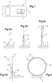
- Figure 1 shows a manufacturing system 1 adapted to manufacture an ophthalmic lens.
- the manufacturing system 1 comprises a device 3 and a support 5.
- the device 3 is suitable for manufacturing a part 7 of the ophthalmic lens using an additive manufacturing technology.
- additive manufacturing technology refers to processes that manufacture solid objects by juxtaposing volume elements or voxels. In the case of the present invention, the part 7 of the ophthalmic lens is thus manufactured volume element by volume element, layer by layer.
- the additive manufacturing technology may be in practice stereolithography (SLA) or polymer jetting or continuous liquid interface production (CLIP) technology.
- the device 3 comprises a control unit (not shown on Figure 1 ).
- This control unit includes a microprocessor and a memory.
- the memory stores instructions that allow the manufacturing system 1 to implement a method for manufacturing the ophthalmic lens as described below when these instructions are executed by the microprocessor.
- the part 7 of the ophthalmic lens comprises at least one useful optical surface and a peripheral region surrounding at least in part said useful optical surface.
- the part 7 of the ophthalmic lens comprises two opposite faces and an edge extending between the two faces.
- the peripheral region of the part 7 of the ophthalmic lens comprises at least a portion of the edge and a portion of at least one of the two faces.
- the peripheral region is a non-useful optical part.
- useful optical surface is understood to mean the surface of the ophthalmic lens adapted to modify the propagation and the transmission of an optical beam going through said ophthalmic lens.
- the useful optical surface is thus the portion of the ophthalmic lens adapted to the wearer's optical prescription. Said differently, the useful optical surface is the portion of the ophthalmic lens that may be crossed by the wearer's gaze direction when the ophthalmic lens is worn by the wearer.
- the memory comprised in the device 3 also stores elements for defining the ophthalmic lens to be manufactured, especially features defining the useful optical surface.
- the support 5 shown on Figure 1 is designed to sustain the part 7 of the ophthalmic lens being manufactured.
- the word “ bear” is understood to mean maintaining the part 7 of the ophthalmic lens in a certain position thanks to the support 5.
- the word “ bear " is in no way intended to limit the contact region between the part 7 of the ophthalmic lens and the support 5 to a contact from the bottom of said part 7 of the ophthalmic lens.
- the support 5 may thus bear the part 7 of the ophthalmic lens from the top of said part 7, as further described below.
- the support 5 is manufactured by the additive manufacturing technology.
- the support 5 is configured and dimensioned so that when the support bears the part 7 of the ophthalmic lens being manufactured, the useful optical surface is free from any contact with said support 5.
- the shape and dimensions of the support 5 are determined considering the features of the useful optical surface of the ophthalmic lens being manufactured. These features include the shape of the manufactured ophthalmic lens (concave or convex) and/or the optical prescription and/or the shape and dimensions of a frame in which the ophthalmic lens will be mounted.
- the manufacturing system 1 shown on Figure 1 and described previously is suitable to execute a method for manufacturing an ophthalmic lens using the additive manufacturing technology.
- This method comprises a step of providing the support 5 (for instance by producing the support 5 by additive manufacturing) as described previously.
- the method also comprises a step of manufacturing the part 7 of the ophthalmic lens, using the additive manufacturing technology.
- a portion of the peripheral region of the part 7 of the ophthalmic lens is in contact with the support 5 so that the support 5 bears the part 7 of the ophthalmic lens being manufactured.
- the useful optical surface is free from any contact with the support 5.
- Figures 2a, 2b and 2c schematically show a concave ophthalmic lens at different manufacturing stages according to a first exemplary embodiment of the manufacturing method just mentioned.
- This first embodiment corresponds to the manufacturing of the ophthalmic lens from the bottom to the top of the ophthalmic lens.
- Figure 2a represents a first part 21 of the ophthalmic lens manufactured on the support 5 by the additive manufacturing technology at a first stage of the step of manufacturing.
- Figure 2b shows a second part 23 of the ophthalmic lens manufactured at a second stage of the step of manufacturing.
- the second part 23 is obtained from the first part 21 by adding layers by additive manufacturing on the first part 21.
- Figure 2c shows a final concave ophthalmic lens 25 obtained by adding layers on the second part 23.
- the centre of gravity G of the current part (i.e. the first part 21, the second part 23 or the third part 25) of the ophthalmic lens being manufactured is represented on Figures 2a, 2b and 2c .
- the vertical line L going through the centre of gravity G of said current part (i.e. the first part 21, the second part 23 or the third part 25) is also identified on Figures 2a, 2b and 2c .
- the support 5 bears the concerned part (i.e. the first part 21, the second part 23 or the third part 25) of the ophthalmic lens.
- Said concerned part (i.e. the first part 21, the second part 23 or the third part 25) of the ophthalmic lens thus lies on a bearing surface of the support 5.
- the bearing surface is defined as the contact surface between the concerned part (i.e. the first part 21, the second part 23 or the third part 25) of the ophthalmic lens and the support 5.
- the vertical line L going through the centre of gravity G crosses said bearing surface.
- the support 5 is arranged according to the ophthalmic lens to be manufactured. As an example, the support 5 is arranged before the step of manufacturing, depending on the predetermined geometry of the ophthalmic lens to be manufactured. The support 5 is thus arranged in shape and orientation to prevent the concerned part (i.e. the first part 21, the second part 23 or the third part 25) of the ophthalmic lens from collapsing or being deformed while being manufactured.
- the support is in a fixed position during the manufacturing process.
- the support 5 may be tilted by a tilt angle ⁇ .
- Figure 2d schematically shows the second stage of manufacturing for which the support has been tilted to prevent the final concave ophthalmic lens from collapsing.
- the second part 23 is represented with the remaining part 24 to manufacture to obtain the final concave ophthalmic lens 25.
- the tilt angle ⁇ is determined according to the predetermined geometry of the ophthalmic lens.
- the centre of gravity G of the part 23 of the ophthalmic lens and the vertical line L going through the centre of gravity G of said part 7 are also identified on Figure 2d .
- the tilt angle ⁇ is defined as the angle between the vertical line L going through the centre of gravity G of the part 23 of the ophthalmic lens and a direction perpendicular to the plane defined by the bearing surface.
- Said tilt angle ⁇ may be fixed during said step of manufacturing.
- Said tilt angle ⁇ corresponds to the optimal angle to prevent the concerned part (i.e. the first part 21, the second part 23 or the third part 25) of the ophthalmic lens from collapsing or being deformed while being manufactured.
- the tilt angle ⁇ is substantially at 0°.
- the shape and the orientation of the support 5 are continuously varied during the step of manufacturing.
- the tilt angle ⁇ is continuously modified during the step of manufacturing in order to prevent the part of the ophthalmic lens from collapsing or being deformed at each stage of manufacturing.
- the support 5 lies in a resin bath while said part 7 of the ophthalmic lens is manufactured in order to reduce the impact of the gravity.
- the part 7 of the ophthalmic lens is formed by hardening a resin.
- the part 7 of the ophthalmic lens is thus plunged into said resin bath.
- a layer of the resin is polymerised in an upper surface of the resin bath.
- the support 5 is moved down to polymerise another layer and so on until the ophthalmic lens is completely formed.
- Figure 3 shows a front view of a concave ophthalmic lens on a support according to this first exemplary embodiment.
- the final concave ophthalmic lens 25 comprises a peripheral region 31 and a useful optical surface 33.
- the peripheral region 31 surrounds the useful optical surface 33.
- the peripheral region 31 is considered as a non-useful optical surface.
- the support 5 sustains the final concave ophthalmic lens 25 contacting the peripheral region 31.
- the part 7 of the ophthalmic lens may contact the support 5 via a frangible portion (not shown on Figure 3 ) possibly made by additive manufacturing.
- the frangible portion secures the part 7 of the ophthalmic lens to the support 5 and eases later separation of the ophthalmic lens from the support 5.
- Figure 4 schematically shows a front view of a convex ophthalmic lens on the support according to a second exemplary embodiment of the proposed manufacturing method.
- a final convex ophthalmic lens 45 comprises the peripheral region 31 and the useful optical surface 33.
- the support 5 sustains the final convex ophthalmic lens 45, contacting the peripheral region 31.
- the support 5 fits closely the peripheral region 31 of the ophthalmic lens.
- the support 5 has a shape which is complementary to the portion of the peripheral region 31.
- Figure 5 schematically shows a side view of the final convex ophthalmic lens on the support according to the second exemplary embodiment.
- the final convex ophthalmic lens is sustained by the support 5 by imbedding itself in the support 5.
- the support 5 is contacting the final convex ophthalmic lens only via the peripheral region 31.
- the useful optical surface 33 is free from any contact with the support 5.
- the contact between the part 7 of the ophthalmic lens via the peripheral region 31 and the support 5 is discontinuous.
- the ophthalmic lens further comprises a discontinuous linking portion between said part 7 of the ophthalmic lens and said support 5. This continuous linking is adapted to easily remove the manufactured ophthalmic lens from the support.
- Figure 6 schematically shows a side view of a convex ophthalmic lens on a support according to a third exemplary embodiment of the invention.
- the stability of the ophthalmic lens being manufactured is realised thanks to a lattice framework 60, as shown on Figure 6 .
- the lattice framework 60 maintains the part 7 of the ophthalmic lens being manufactured by being fixed on the peripheral region 31.
- the useful optical surface 33 is free from any contact with the lattice framework 60.
- the lattice framework 60 is adapted to prevent the part 7 of the ophthalmic lens from collapsing or being deformed while being manufactured.
- the centre of gravity G of the part 7 of the ophthalmic lens is identified on Figure 6 .
- the vertical line L going through the centre of gravity G of said part 7 is also identified.
- the vertical line L intersects said bearing surface in order to prevent the part 7 of the ophthalmic lens from collapsing or being deformed while being manufactured.
- the support 5 is adapted to sustain a plurality of ophthalmic lenses while being manufactured. Only one support 5 sustains the plurality of ophthalmic lenses.
- the support 5 may be formed by an assembly of several individual supports, each part 7 of the plurality of the ophthalmic lenses being sustained by its own individual support.
- Figure 7 schematically shows a front view of multiple concave ophthalmic lenses sustained on the support 5 according to a fourth exemplary embodiment of the invention.
- the plurality of parts 7 of the ophthalmic lenses comprises the peripheral region 31 and the useful optical surface 33.
- the support 5 is contacting the plurality of parts 7 of the ophthalmic lenses only via the peripheral region 31.
- the lattice framework 60 maintains the plurality of parts 7 of the ophthalmic lenses.
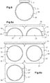
- Figure 8 schematically shows a front view of a concave ophthalmic lens on a support according to a fifth exemplary embodiment of the invention.
- This fifth embodiment corresponds to the manufacturing of the ophthalmic lens from the top to the bottom of the ophthalmic lens.
- the final concave ophthalmic lens 25 also comprises the peripheral region 31 and the useful optical surface 33.
- the support 5 upholds the final concave ophthalmic lens 25 contacting the peripheral region 31.
- the support 5 is adapted to prevent the part 7 of the ophthalmic lens from falling down or being deformed while being manufactured.
- FIGS 9a and 9b schematically show a front view of a plurality of ophthalmic lenses at two different manufacturing stages according to a sixth embodiment of the invention.
- the support 5 sticks to a tray 90.
- the tray 90 is controlled by the control unit previously mentioned.
- the tray 90 is made of a durable material, such as metal.
- the ophthalmic lens is manufactured from the top to the bottom.
- the support 5 and the part 7 of the ophthalmic lens are simultaneously manufactured by additive manufacturing.
- Figure 9a represents two first parts 91, 91' of two ophthalmic lenses manufactured with the support 5 by the additive manufacturing technology at a first stage of the step of manufacturing.
- the two first parts 91, 91' of the ophthalmic lenses comprise the peripheral region 31, 31' and the useful optical surface 33, 33'.
- the support 5 is formed with an assembly of two individual supports 50, 51. The individual support 50 upholds the part 91 of the ophthalmic lens and the individual support 51 upholds the part 91' of the ophthalmic lens.
- the support 5 is contacting the two first parts 91, 91' of the ophthalmic lenses only via the peripheral region 31, 31'.
- Figure 9b shows the plurality of the ophthalmic lenses manufactured at a final stage of the step of manufacturing.
- the final ophthalmic lenses 95, 95' are obtained from the first parts 91, 91' by adding layers by additive manufacturing below the first parts 91, 91'.
- the final ophthalmic lens 95" is completely manufactured after the manufacturing of the final ophthalmic lenses 95, 95'.
- the support 5 is adapted to uphold more than two ophthalmic lenses as shown on Figure 9b .
- the support 5 is formed by an assembly of several individual supports 50, 51, 52. Each of the plurality of ophthalmic lenses is upheld by its own individual support 50, 51, 52. Each individual support 50, 51, 52 contacts with each other, allowing the manufacturing of the plurality of the ophthalmic lenses in any direction.
- the plurality of ophthalmic lenses is manufactured at once.
- the final ophthalmic lens is directly obtained from the proposed manufacturing method.
- the final ophthalmic lens comprises two opposite faces and an edge extending between the two faces.
- the peripheral region of the final ophthalmic lens comprises at least a portion of the edge and a portion of at least one of the two faces.
- the final ophthalmic lens is configured to be mounted in a rim of a frame.
- the rim has an inner face.
- the edge of the ophthalmic lens, extending between the two faces, substantially matches the inner face of the rim.
Landscapes
- Engineering & Computer Science (AREA)
- Manufacturing & Machinery (AREA)
- Chemical & Material Sciences (AREA)
- Materials Engineering (AREA)
- Mechanical Engineering (AREA)
- Physics & Mathematics (AREA)
- Optics & Photonics (AREA)
- Health & Medical Sciences (AREA)
- Ophthalmology & Optometry (AREA)
- Eyeglasses (AREA)
Abstract
- providing a support (5),
- manufacturing a part of the ophthalmic lens comprising a portion of said peripheral region (31), and being in contact with the support (5) by said portion of the peripheral region (31) so that the support (5) bears the part of the ophthalmic lens being manufactured while said useful optical surface (31) is free from any contact with the support (5).
Description
- The invention relates to the manufacturing of ophthalmic lenses.
- More precisely the invention relates to a method for manufacturing an ophthalmic lens, a support designed to sustain the ophthalmic lens being manufactured and a manufacturing system.
- Using an additive manufacturing technology to manufacture an ophthalmic lens is of interest because the obtained ophthalmic lens is directly shaped to fit the frame that shall carry the ophthalmic lens and/or the obtained ophthalmic lens complies with the wearer's optical prescription.
- The additive manufacturing process needs to be precisely performed; in particular a new layer needs to be positioned very accurately on the already polymerised layer to correctly manufacture the ophthalmic lens. This delicate process leads to manufacture the ophthalmic lens on a support which will maintain the ophthalmic lens during the whole additive manufacturing process.
- Document
WO2015092017 describes a method to print a three-dimensional structure, such as an ophthalmic lens, by superposing layers of different materials. The whole printing structure lies on a support and some layers may be removed during the process to get the final three-dimensional structure. - The final three-dimensional structure is not ready for use as the useful surface presents some optical defects due to the contact with the support and other layers. Some heavy post-processing steps on the final structure, such as polishing, are thus necessary.
- In this context, the invention provides a method for manufacturing an ophthalmic lens using an additive manufacturing technology in order to directly obtain an ophthalmic lens ready for use, without any post-processing treatment.
- The invention consists in a method for manufacturing an ophthalmic lens using an additive manufacturing technology, said ophthalmic lens having at least one useful optical surface and a peripheral region surrounding at least in part said useful optical surface, the method comprising the steps of:
- providing a support,
- manufacturing a part of the ophthalmic lens comprising a portion of said peripheral region and being in contact with the support by said portion of the peripheral region so that the support bears the part of the ophthalmic lens being manufactured while said useful optical surface is free from any contact with the support.
- Thanks to the invention, the ophthalmic lens being manufactured is borne by the support contacting the peripheral region. This peripheral region corresponds to a non-useful optical part and the useful optical surface of the ophthalmic lens is manufactured being free from any contact with the support. Thus, this optical surface is manufactured with the correct optical characteristics and is free from any optical defects. Post-processing treatments needed to modify the optical surface of the ophthalmic lens are thus not necessary and the ophthalmic lens can be directly used in a frame. This does not exclude however the possibility to add any type of coating on the ophthalmic lens.
- Other advantageous features of the invention are the following ones:
- said support has a shape complementary to the portion of the peripheral region of the ophthalmic lens;
- said support sustains said part of the ophthalmic lens;
- said part of the ophthalmic lens lies on a bearing surface of said support, the vertical line going through the centre of gravity of said part of the ophthalmic lens intersecting said bearing surface of the support;
- the geometry or the orientation of the support is arranged before the step of manufacturing the ophthalmic lens in order to prevent said part of the ophthalmic lens from collapsing or being deformed while being manufactured;
- the orientation of the support is continuously varied during the step of manufacturing the ophthalmic lens in order to prevent said part of the ophthalmic lens from collapsing or being deformed while being manufactured;
- said support upholds said part of the ophthalmic lens;
- the ophthalmic lens further comprises a discontinuous linking portion between said part of the ophthalmic lens and said support;
- the ophthalmic lens directly obtained from the manufacturing comprises two opposite faces and an edge extending between the two faces, the peripheral region comprising a portion of at least one of the two faces; and
- the ophthalmic lens is configured to be mounted in a rim of a frame, said rim having an inner face, wherein the ophthalmic lens directly obtained from the manufacturing comprises two opposite faces and an edge extending between the two faces, said edge substantially matching the inner face of the rim.
- The invention also provides a support designed to bear a part of an ophthalmic lens being manufactured by an additive manufacturing technology, the ophthalmic lens having at least one useful optical surface and a peripheral region surrounding at least in part said useful optical surface, the support being configured so that when the support bears the part of the ophthalmic lens being manufactured by a portion of the peripheral region, the useful optical surface is free from any contact with the support.
- The support has shape and dimensions determined by features of the useful optical surface of the ophthalmic lens to be manufactured. The support is manufactured using said additive manufacturing technology.
- The invention also describes a manufacturing system comprising:
- a support designed to bear a part of an ophthalmic lens being manufactured by an additive manufacturing technology, the ophthalmic lens having at least one useful optical surface and a peripheral region surrounding at least in part said useful optical surface; and
- a device suitable for manufacturing said part of the ophthalmic lens using said additive manufacturing technology,
- The following description, given with regard to the appended drawings, which are given by way of non-limiting examples, will allow what the invention consists of and how it can be carried out to be understood.
- In the appended drawings:
-
Figure 1 shows an exemplary manufacturing system adapted to manufacture an ophthalmic lens according to the invention; -
Figures 2a, 2b, 2c and 2d schematically show a concave ophthalmic lens at different manufacturing stages according to a first exemplary embodiment of the invention; -
Figure 3 schematically shows a front view of a concave ophthalmic lens on a support according to the first exemplary embodiment of the invention; -
Figure 4 schematically shows a front view of a convex ophthalmic lens on a support according to a second exemplary embodiment of the invention; -
Figure 5 schematically shows a side view of a convex ophthalmic lens on a support according to the second exemplary embodiment of the invention; -
Figure 6 schematically shows a side view of a convex ophthalmic lens on a support according to a third exemplary embodiment of the invention; -
Figure 7 schematically shows a front view of multiple concave ophthalmic lenses on a support according to a fourth exemplary embodiment of the invention; -
Figure 8 schematically shows a front view of a concave ophthalmic lens on a support according to a fifth exemplary embodiment of the invention; and -
Figures 9a and 9b schematically show a front view of a plurality of ophthalmic lenses at two different manufacturing stages according to a sixth embodiment of the invention. -
Figure 1 shows amanufacturing system 1 adapted to manufacture an ophthalmic lens. - The
manufacturing system 1 comprises adevice 3 and asupport 5. Thedevice 3 is suitable for manufacturing apart 7 of the ophthalmic lens using an additive manufacturing technology. The expression "additive manufacturing technology" refers to processes that manufacture solid objects by juxtaposing volume elements or voxels. In the case of the present invention, thepart 7 of the ophthalmic lens is thus manufactured volume element by volume element, layer by layer. The additive manufacturing technology may be in practice stereolithography (SLA) or polymer jetting or continuous liquid interface production (CLIP) technology. - The
device 3 comprises a control unit (not shown onFigure 1 ). This control unit includes a microprocessor and a memory. The memory stores instructions that allow themanufacturing system 1 to implement a method for manufacturing the ophthalmic lens as described below when these instructions are executed by the microprocessor. - The
part 7 of the ophthalmic lens comprises at least one useful optical surface and a peripheral region surrounding at least in part said useful optical surface. Thepart 7 of the ophthalmic lens comprises two opposite faces and an edge extending between the two faces. The peripheral region of thepart 7 of the ophthalmic lens comprises at least a portion of the edge and a portion of at least one of the two faces. The peripheral region is a non-useful optical part. The expression "useful optical surface" is understood to mean the surface of the ophthalmic lens adapted to modify the propagation and the transmission of an optical beam going through said ophthalmic lens. The useful optical surface is thus the portion of the ophthalmic lens adapted to the wearer's optical prescription. Said differently, the useful optical surface is the portion of the ophthalmic lens that may be crossed by the wearer's gaze direction when the ophthalmic lens is worn by the wearer. - The memory comprised in the
device 3 also stores elements for defining the ophthalmic lens to be manufactured, especially features defining the useful optical surface. - The
support 5 shown onFigure 1 is designed to sustain thepart 7 of the ophthalmic lens being manufactured. The word "bear" is understood to mean maintaining thepart 7 of the ophthalmic lens in a certain position thanks to thesupport 5. The word "bear" is in no way intended to limit the contact region between thepart 7 of the ophthalmic lens and thesupport 5 to a contact from the bottom of saidpart 7 of the ophthalmic lens. Thesupport 5 may thus bear thepart 7 of the ophthalmic lens from the top of saidpart 7, as further described below. - In these examples described here, the
support 5 is manufactured by the additive manufacturing technology. Thesupport 5 is configured and dimensioned so that when the support bears thepart 7 of the ophthalmic lens being manufactured, the useful optical surface is free from any contact with saidsupport 5. - The shape and dimensions of the
support 5 are determined considering the features of the useful optical surface of the ophthalmic lens being manufactured. These features include the shape of the manufactured ophthalmic lens (concave or convex) and/or the optical prescription and/or the shape and dimensions of a frame in which the ophthalmic lens will be mounted. - The
manufacturing system 1 shown onFigure 1 and described previously is suitable to execute a method for manufacturing an ophthalmic lens using the additive manufacturing technology. - This method comprises a step of providing the support 5 (for instance by producing the
support 5 by additive manufacturing) as described previously. The method also comprises a step of manufacturing thepart 7 of the ophthalmic lens, using the additive manufacturing technology. During the step of manufacturing, a portion of the peripheral region of thepart 7 of the ophthalmic lens is in contact with thesupport 5 so that thesupport 5 bears thepart 7 of the ophthalmic lens being manufactured. During the step of manufacturing, the useful optical surface is free from any contact with thesupport 5. -
Figures 2a, 2b and 2c schematically show a concave ophthalmic lens at different manufacturing stages according to a first exemplary embodiment of the manufacturing method just mentioned. This first embodiment corresponds to the manufacturing of the ophthalmic lens from the bottom to the top of the ophthalmic lens. -
Figure 2a represents afirst part 21 of the ophthalmic lens manufactured on thesupport 5 by the additive manufacturing technology at a first stage of the step of manufacturing.Figure 2b shows asecond part 23 of the ophthalmic lens manufactured at a second stage of the step of manufacturing. Thesecond part 23 is obtained from thefirst part 21 by adding layers by additive manufacturing on thefirst part 21.Figure 2c shows a final concaveophthalmic lens 25 obtained by adding layers on thesecond part 23. - The centre of gravity G of the current part (i.e. the
first part 21, thesecond part 23 or the third part 25) of the ophthalmic lens being manufactured is represented onFigures 2a, 2b and 2c .The vertical line L going through the centre of gravity G of said current part (i.e. thefirst part 21, thesecond part 23 or the third part 25) is also identified onFigures 2a, 2b and 2c . - As shown on
Figures 2a, 2b and 2c , thesupport 5 bears the concerned part (i.e. thefirst part 21, thesecond part 23 or the third part 25) of the ophthalmic lens. Said concerned part (i.e. thefirst part 21, thesecond part 23 or the third part 25) of the ophthalmic lens thus lies on a bearing surface of thesupport 5. The bearing surface is defined as the contact surface between the concerned part (i.e. thefirst part 21, thesecond part 23 or the third part 25) of the ophthalmic lens and thesupport 5. The vertical line L going through the centre of gravity G crosses said bearing surface. - The
support 5 is arranged according to the ophthalmic lens to be manufactured. As an example, thesupport 5 is arranged before the step of manufacturing, depending on the predetermined geometry of the ophthalmic lens to be manufactured. Thesupport 5 is thus arranged in shape and orientation to prevent the concerned part (i.e. thefirst part 21, thesecond part 23 or the third part 25) of the ophthalmic lens from collapsing or being deformed while being manufactured. - In the example just described, the support is in a fixed position during the manufacturing process. According to a possible variation, the
support 5 may be tilted by a tilt angle α.Figure 2d schematically shows the second stage of manufacturing for which the support has been tilted to prevent the final concave ophthalmic lens from collapsing. Thesecond part 23 is represented with the remainingpart 24 to manufacture to obtain the final concaveophthalmic lens 25. - The tilt angle α is determined according to the predetermined geometry of the ophthalmic lens. The centre of gravity G of the
part 23 of the ophthalmic lens and the vertical line L going through the centre of gravity G of saidpart 7 are also identified onFigure 2d . The tilt angle α is defined as the angle between the vertical line L going through the centre of gravity G of thepart 23 of the ophthalmic lens and a direction perpendicular to the plane defined by the bearing surface. Said tilt angle α may be fixed during said step of manufacturing. Said tilt angle α corresponds to the optimal angle to prevent the concerned part (i.e. thefirst part 21, thesecond part 23 or the third part 25) of the ophthalmic lens from collapsing or being deformed while being manufactured. As an example, onFigures 2a, 2b and 2c , the tilt angle α is substantially at 0°. - As an alternative, the shape and the orientation of the
support 5 are continuously varied during the step of manufacturing. As an example, the tilt angle α is continuously modified during the step of manufacturing in order to prevent the part of the ophthalmic lens from collapsing or being deformed at each stage of manufacturing. - As another alternative, the
support 5 lies in a resin bath while saidpart 7 of the ophthalmic lens is manufactured in order to reduce the impact of the gravity. This may for instance be the case when thepart 7 of the ophthalmic lens is formed by hardening a resin. Thepart 7 of the ophthalmic lens is thus plunged into said resin bath. A layer of the resin is polymerised in an upper surface of the resin bath. Thesupport 5 is moved down to polymerise another layer and so on until the ophthalmic lens is completely formed. -
Figure 3 shows a front view of a concave ophthalmic lens on a support according to this first exemplary embodiment. The final concaveophthalmic lens 25 comprises aperipheral region 31 and a usefuloptical surface 33. Theperipheral region 31 surrounds the usefuloptical surface 33. Theperipheral region 31 is considered as a non-useful optical surface. Thesupport 5 sustains the final concaveophthalmic lens 25 contacting theperipheral region 31. - As an example, the
part 7 of the ophthalmic lens may contact thesupport 5 via a frangible portion (not shown onFigure 3 ) possibly made by additive manufacturing. The frangible portion secures thepart 7 of the ophthalmic lens to thesupport 5 and eases later separation of the ophthalmic lens from thesupport 5. -
Figure 4 schematically shows a front view of a convex ophthalmic lens on the support according to a second exemplary embodiment of the proposed manufacturing method. - As shown in
Figure 4 , a final convexophthalmic lens 45 comprises theperipheral region 31 and the usefuloptical surface 33. As described previously for the concave ophthalmic lens, thesupport 5 sustains the final convexophthalmic lens 45, contacting theperipheral region 31. However, in this case, thesupport 5 fits closely theperipheral region 31 of the ophthalmic lens. Thesupport 5 has a shape which is complementary to the portion of theperipheral region 31. -
Figure 5 schematically shows a side view of the final convex ophthalmic lens on the support according to the second exemplary embodiment. As shown onFigure 5 , the final convex ophthalmic lens is sustained by thesupport 5 by imbedding itself in thesupport 5. Thesupport 5 is contacting the final convex ophthalmic lens only via theperipheral region 31. The usefuloptical surface 33 is free from any contact with thesupport 5. - As an alternative, the contact between the
part 7 of the ophthalmic lens via theperipheral region 31 and thesupport 5 is discontinuous. The ophthalmic lens further comprises a discontinuous linking portion between saidpart 7 of the ophthalmic lens and saidsupport 5. This continuous linking is adapted to easily remove the manufactured ophthalmic lens from the support. -
Figure 6 schematically shows a side view of a convex ophthalmic lens on a support according to a third exemplary embodiment of the invention. According to this embodiment, the stability of the ophthalmic lens being manufactured is realised thanks to alattice framework 60, as shown onFigure 6 . Thelattice framework 60 maintains thepart 7 of the ophthalmic lens being manufactured by being fixed on theperipheral region 31. The usefuloptical surface 33 is free from any contact with thelattice framework 60. Thelattice framework 60 is adapted to prevent thepart 7 of the ophthalmic lens from collapsing or being deformed while being manufactured. - The centre of gravity G of the
part 7 of the ophthalmic lens is identified onFigure 6 . The vertical line L going through the centre of gravity G of saidpart 7 is also identified. The vertical line L intersects said bearing surface in order to prevent thepart 7 of the ophthalmic lens from collapsing or being deformed while being manufactured. - In the present example, the
support 5 is adapted to sustain a plurality of ophthalmic lenses while being manufactured. Only onesupport 5 sustains the plurality of ophthalmic lenses. As an alternative, thesupport 5 may be formed by an assembly of several individual supports, eachpart 7 of the plurality of the ophthalmic lenses being sustained by its own individual support. -
Figure 7 schematically shows a front view of multiple concave ophthalmic lenses sustained on thesupport 5 according to a fourth exemplary embodiment of the invention. The plurality ofparts 7 of the ophthalmic lenses comprises theperipheral region 31 and the usefuloptical surface 33. Thesupport 5 is contacting the plurality ofparts 7 of the ophthalmic lenses only via theperipheral region 31. Thelattice framework 60 maintains the plurality ofparts 7 of the ophthalmic lenses. -
Figure 8 schematically shows a front view of a concave ophthalmic lens on a support according to a fifth exemplary embodiment of the invention. This fifth embodiment corresponds to the manufacturing of the ophthalmic lens from the top to the bottom of the ophthalmic lens. As described in the previous embodiments, the final concaveophthalmic lens 25 also comprises theperipheral region 31 and the usefuloptical surface 33. Thesupport 5 upholds the final concaveophthalmic lens 25 contacting theperipheral region 31. According to this embodiment, thesupport 5 is adapted to prevent thepart 7 of the ophthalmic lens from falling down or being deformed while being manufactured. -
Figures 9a and 9b schematically show a front view of a plurality of ophthalmic lenses at two different manufacturing stages according to a sixth embodiment of the invention. According to this sixth embodiment, thesupport 5 sticks to atray 90. Thetray 90 is controlled by the control unit previously mentioned. Thetray 90 is made of a durable material, such as metal. - According to this embodiment, the ophthalmic lens is manufactured from the top to the bottom. The
support 5 and thepart 7 of the ophthalmic lens are simultaneously manufactured by additive manufacturing. -
Figure 9a represents twofirst parts 91, 91' of two ophthalmic lenses manufactured with thesupport 5 by the additive manufacturing technology at a first stage of the step of manufacturing. The twofirst parts 91, 91' of the ophthalmic lenses comprise theperipheral region 31, 31' and the usefuloptical surface 33, 33'. Thesupport 5 is formed with an assembly of twoindividual supports individual support 50 upholds thepart 91 of the ophthalmic lens and theindividual support 51 upholds the part 91' of the ophthalmic lens. Thesupport 5 is contacting the twofirst parts 91, 91' of the ophthalmic lenses only via theperipheral region 31, 31'. -
Figure 9b shows the plurality of the ophthalmic lenses manufactured at a final stage of the step of manufacturing. The finalophthalmic lenses 95, 95' are obtained from thefirst parts 91, 91' by adding layers by additive manufacturing below thefirst parts 91, 91'. The finalophthalmic lens 95" is completely manufactured after the manufacturing of the finalophthalmic lenses 95, 95'. Thesupport 5 is adapted to uphold more than two ophthalmic lenses as shown onFigure 9b . Thesupport 5 is formed by an assembly of severalindividual supports individual support individual support - The final ophthalmic lens is directly obtained from the proposed manufacturing method. The final ophthalmic lens comprises two opposite faces and an edge extending between the two faces. The peripheral region of the final ophthalmic lens comprises at least a portion of the edge and a portion of at least one of the two faces.
- In practice, the final ophthalmic lens is configured to be mounted in a rim of a frame. The rim has an inner face. In this case, the edge of the ophthalmic lens, extending between the two faces, substantially matches the inner face of the rim.
Claims (14)
- Method for manufacturing an ophthalmic lens using an additive manufacturing technology, said ophthalmic lens having at least one useful optical surface (33; 33') and a peripheral region (31; 31') surrounding at least in part said useful optical surface (33; 33'), the method comprising the steps of:- providing a support (5),- manufacturing a part (7; 21; 23; 25; 91; 91') of the ophthalmic lens comprising a portion of said peripheral region (31; 31'), and being in contact with the support (5) by said portion of the peripheral region (31; 31') so that the support (5) bears the part (7; 21; 23; 25; 91; 91') of the ophthalmic lens being manufactured while said useful optical surface (33; 33') is free from any contact with the support (5).
- Method according to claim 1, wherein said support (5) has a shape complementary to the portion of the peripheral region (31; 31') of the ophthalmic lens.
- Method according to claim 1 or 2, wherein said support (5) sustains said part (7; 21; 23; 25; 91; 91') of the ophthalmic lens.
- Method according to claim 3, wherein said part (7; 21; 23; 25; 91; 91') of the ophthalmic lens lies on a bearing surface of said support (5), the vertical line (L) going through the centre (G) of gravity of said part (7; 21; 23; 25; 91; 91') of the ophthalmic lens intersecting said bearing surface of the support (5).
- Method according to claim 3 or 4, wherein the geometry or the orientation of the support (5) is arranged before the step of manufacturing the ophthalmic lens.
- Method according to claim 3 or 4, wherein the orientation of the support (5) is continuously varied during the step of manufacturing the ophthalmic lens.
- Method according to claim 1 or 2, wherein said support (5) upholds said part (7; 21; 23; 25; 91; 91') of the ophthalmic lens.
- Method according to any of claims 1 to 7, wherein the ophthalmic lens further comprises a discontinuous linking portion between said part (7; 21; 23; 25; 91; 91') of the ophthalmic lens and said support (5).
- Method according to any of claims 1 to 8, wherein the ophthalmic lens directly obtained from the manufacturing comprises two opposite faces and an edge extending between the two faces, the peripheral region (31; 31') comprising a portion of at least one of the two faces.
- Method according to any of claims 1 to 8, wherein the ophthalmic lens is configured to be mounted in a rim of a frame, said rim having an inner face, wherein the ophthalmic lens directly obtained from the manufacturing comprises two opposite faces and an edge extending between the two faces, said edge substantially matching the inner face of the rim.
- Support (5) designed to bear a part of an ophthalmic lens being manufactured by an additive manufacturing technology, the ophthalmic lens having at least one useful optical surface (33; 33') and a peripheral region (31; 31') surrounding at least in part said useful optical surface (33; 33'), the support (5) being configured so that when the support (5) bears the part (7; 21; 23; 25; 91; 91') of the ophthalmic lens being manufactured by a portion of the peripheral region, the useful optical surface (33; 33') is free from any contact with the support (5).
- Support (5) according to claim 11, having shape and dimensions determined by features of the useful optical surface (33; 33') of the ophthalmic lens to be manufactured.
- Support (5) according to claim 11 or 12, being manufactured using said additive manufacturing technology.
- Manufacturing system (1) comprising:- a support (5) designed to bear a part (7; 21; 23; 25; 91; 91') of an ophthalmic lens being manufactured by an additive manufacturing technology, the ophthalmic lens having at least one useful optical surface (33; 33') and a peripheral region (31; 31') surrounding at least in part said useful optical surface (33; 33'); and- a device suitable for manufacturing said part (7; 21; 23; 25; 91; 91') of the ophthalmic lens using said additive manufacturing technology,whereby said support (5) is in contact with a portion of the peripheral region (31; 31') of the part (7; 21; 23; 25; 91; 91') of the ophthalmic lens being manufactured while said useful optical surface (33; 33') is free from any contact with the support (5).
Priority Applications (7)
| Application Number | Priority Date | Filing Date | Title |
|---|---|---|---|
| EP17306425.4A EP3473418B1 (en) | 2017-10-19 | 2017-10-19 | Method for manufacturing an ophthalmic lens |
| US16/756,868 US20210187863A1 (en) | 2017-10-19 | 2018-10-18 | Method for manufacturing an ophthalmic lens, support and manufacturing system |
| CN201880065840.2A CN111201128B (en) | 2017-10-19 | 2018-10-18 | Method, support and manufacturing system for manufacturing ophthalmic lenses |
| KR1020207014177A KR102542885B1 (en) | 2017-10-19 | 2018-10-18 | Method, support and manufacturing system for ophthalmic lenses |
| PCT/EP2018/078620 WO2019077068A1 (en) | 2017-10-19 | 2018-10-18 | Method for manufacturing an ophthalmic lens, support and manufacturing system |
| JP2020518027A JP7444771B2 (en) | 2017-10-19 | 2018-10-18 | Method, support, and manufacturing system for manufacturing eyeglass lenses |
| US18/758,116 US20240351292A1 (en) | 2017-10-19 | 2024-06-28 | Method for manufacturing an ophthalmic lens, support and manufacturing system |
Applications Claiming Priority (1)
| Application Number | Priority Date | Filing Date | Title |
|---|---|---|---|
| EP17306425.4A EP3473418B1 (en) | 2017-10-19 | 2017-10-19 | Method for manufacturing an ophthalmic lens |
Publications (2)
| Publication Number | Publication Date |
|---|---|
| EP3473418A1 true EP3473418A1 (en) | 2019-04-24 |
| EP3473418B1 EP3473418B1 (en) | 2023-12-06 |
Family
ID=60201472
Family Applications (1)
| Application Number | Title | Priority Date | Filing Date |
|---|---|---|---|
| EP17306425.4A Active EP3473418B1 (en) | 2017-10-19 | 2017-10-19 | Method for manufacturing an ophthalmic lens |
Country Status (6)
| Country | Link |
|---|---|
| US (2) | US20210187863A1 (en) |
| EP (1) | EP3473418B1 (en) |
| JP (1) | JP7444771B2 (en) |
| KR (1) | KR102542885B1 (en) |
| CN (1) | CN111201128B (en) |
| WO (1) | WO2019077068A1 (en) |
Families Citing this family (6)
| Publication number | Priority date | Publication date | Assignee | Title |
|---|---|---|---|---|
| KR102361146B1 (en) * | 2020-11-28 | 2022-02-09 | 동서대학교 산학협력단 | Setting method the output direction when making a character figure product by 3D printing |
| US12140820B2 (en) * | 2021-05-04 | 2024-11-12 | Khalifa University of Science and Technology | Method of manufacturing contact lens for treating color vision deficiency |
| US11899289B2 (en) | 2021-05-04 | 2024-02-13 | Khalifa University of Science and Technology | Contact lens for treating color vision deficiency and method of manufacturing same |
| AT525346B1 (en) * | 2022-07-07 | 2023-03-15 | Genera Printer Gmbh | Additive manufacturing process |
| EP4344862A1 (en) * | 2022-09-30 | 2024-04-03 | Essilor International | Method for additively manufacturing an ophthalmic device and manufacturing system configured to carry out such a method |
| US12447689B2 (en) * | 2022-11-08 | 2025-10-21 | Lung Biotechnology Pbc | Method for manufacturing low modulus articles |
Citations (7)
| Publication number | Priority date | Publication date | Assignee | Title |
|---|---|---|---|---|
| WO2009041707A2 (en) * | 2007-09-28 | 2009-04-02 | Fujifilm Corporation | Manufacturing method of optical member, optical member manufacturing apparatus and optical member |
| WO2015092017A1 (en) | 2013-12-20 | 2015-06-25 | Luxexcel Holding B.V. | Method for printing a three dimensional structure and apparatus therefore |
| US20150241714A1 (en) * | 2012-09-28 | 2015-08-27 | Essilor International (Compagnie Generale D'optique) | Method for manufacturing an ophthalmic lens |
| US20150277150A1 (en) * | 2014-03-28 | 2015-10-01 | Essilor International (Compagnie Generale D'optique) | Ophthalmic lens and process for manufacturing such a lens |
| US20160101573A1 (en) * | 2013-06-07 | 2016-04-14 | Essilor International (Compagnie Générale d'Optique) | Process and machine for manufacturing an ophthalmic lens |
| WO2016075563A1 (en) * | 2014-11-11 | 2016-05-19 | Indizen Optical Technologies, S.L. | Eyewear lens production by additive techniques |
| EP3181338A1 (en) * | 2015-12-16 | 2017-06-21 | OCE-Technologies B.V. | Printing method for forming a three-dimensional body with overhang |
Family Cites Families (41)
| Publication number | Priority date | Publication date | Assignee | Title |
|---|---|---|---|---|
| JPH0796239A (en) * | 1993-09-28 | 1995-04-11 | Nikon Corp | Apparatus and method for manufacturing plastic lens |
| US6829107B2 (en) * | 2000-06-17 | 2004-12-07 | Carl-Zeiss-Stiftung | Device for mounting an optical element, for example a lens element in a lens |
| US7235195B2 (en) * | 2002-09-06 | 2007-06-26 | Novartis Ag | Method for making opthalmic devices |
| US7481647B2 (en) * | 2004-06-14 | 2009-01-27 | Align Technology, Inc. | Systems and methods for fabricating 3-D objects |
| JP2007192845A (en) * | 2006-01-17 | 2007-08-02 | Megane Ryutsu Center:Kk | Eyeglass lens and method for manufacturing eyeglass lens |
| JP2007245516A (en) * | 2006-03-15 | 2007-09-27 | Seiko Epson Corp | Manufacturing method of plastic optical components |
| DE112007002411T5 (en) * | 2006-10-10 | 2009-07-30 | Shofu Inc. | Data generation system, manufacturing method and model data generating program |
| EP2028529B1 (en) * | 2007-12-28 | 2020-09-09 | Essilor International | Method of calculating an optical system according to a given spectacle frame |
| US8940219B2 (en) * | 2007-12-31 | 2015-01-27 | Ronald D. Spoor | Ophthalmic device formed by additive fabrication and method thereof |
| ITVI20080109A1 (en) * | 2008-05-14 | 2009-11-15 | Ettore Maurizio Costabeber | METHOD OF PRODUCTION OF THREE-DIMENSIONAL OBJECTS AND MACHINE USING THIS METHOD |
| FR2945358B1 (en) * | 2009-05-11 | 2011-12-09 | Essilor Int | PRODUCT COMPRISING A FLEXIBLE OPHTHALMIC LENS AND METHOD OF MOUNTING SUCH SOFT OPHTHALMIC LENS ON GLASS OF GLASSES |
| JP2011075690A (en) * | 2009-09-29 | 2011-04-14 | Hoya Corp | Method and device for dyeing plastic lens |
| EP2546043A4 (en) * | 2010-03-09 | 2014-12-24 | Olympus Corp | PROCESS FOR PRODUCING RESIN MOLDED ARTICLE, RESIN MOLDED ARTICLE, RESIN MOLDED ARTICLE FOR ENDOSCOPE, ENDOSCOPE USING RESIN MOLDED ARTICLE, AND APPARATUS FOR PRODUCTION OF RESIN MOLDED ARTICLE |
| EP2834059A1 (en) * | 2012-04-03 | 2015-02-11 | LUXeXcel Holding B.V. | Device and method for producing custom-made spectacles |
| US9662837B2 (en) * | 2012-05-08 | 2017-05-30 | Luxexcel Holding B.V. | Method for printing a three-dimensional structure with smooth surfaces |
| FR2996160B1 (en) * | 2012-09-28 | 2016-07-29 | Essilor Int | METHOD FOR MANUFACTURING AN OPHTHALMIC LENS COMPRISING A MARKING STEP FOR PERMANENT BRANDS ON THE OPHTHALMIC LENS |
| US20140272176A1 (en) * | 2013-03-15 | 2014-09-18 | Johnson & Johnson Vision Care, Inc. | Method and apparatus for spatially locating lens components on a lens precursor |
| WO2014177386A1 (en) * | 2013-04-29 | 2014-11-06 | Essilor International (Compagnie Generale D'optique) | Method of locally thickening an ophthalmic lens |
| FR3006622B1 (en) * | 2013-06-07 | 2015-07-17 | Essilor Int | METHOD FOR MANUFACTURING AN OPHTHALMIC LENS |
| FR3008196B1 (en) * | 2013-07-08 | 2016-12-30 | Essilor Int | METHOD FOR MANUFACTURING AT LEAST ONE OPHTHALMIC LENS |
| US9969135B2 (en) * | 2013-07-31 | 2018-05-15 | Essilor International (Compagnie Generale D'optique) | Additive manufacturing for transparent ophthalmic lens |
| FR3014355B1 (en) * | 2013-12-11 | 2016-02-05 | Essilor Int | METHOD FOR MANUFACTURING AN OPHTHALMIC LENS |
| WO2015092467A1 (en) * | 2013-12-20 | 2015-06-25 | Essilor International (Compagnie Generale D'optique) | Polymer composition and methods using said polymer composition to manufacture ophthalmic lens |
| WO2015139094A1 (en) * | 2014-03-21 | 2015-09-24 | Laing O'rourke Australia Pty Limited | Method and apparatus for fabricating an object |
| US9952448B2 (en) * | 2014-03-26 | 2018-04-24 | Indizen Optical Technologies, S.L. | Eyewear lens production by additive techniques |
| US9933632B2 (en) * | 2014-03-26 | 2018-04-03 | Indizen Optical Technologies, S.L. | Eyewear lens production by multi-layer additive techniques |
| WO2015151004A1 (en) * | 2014-03-31 | 2015-10-08 | Crt Technology, Inc. | Additive manufacturing of molds and methods of making molds and devices therefrom |
| JP6499399B2 (en) * | 2014-04-03 | 2019-04-10 | 株式会社三城ホールディングス | Manufacturing method of burial glasses |
| US10331111B2 (en) * | 2014-04-30 | 2019-06-25 | Materialise N.V. | Systems and methods for customization of objects in additive manufacturing |
| US9579829B2 (en) * | 2014-06-02 | 2017-02-28 | Vadient Optics, Llc | Method for manufacturing an optical element |
| WO2016108062A1 (en) * | 2014-12-31 | 2016-07-07 | Essilor International (Compagnie Generale D'optique) | Eyeglasses equipment including a joint and method for manufacturing such an eyeglasses equipment |
| HUE053311T2 (en) * | 2015-05-22 | 2021-06-28 | Coopervision Int Ltd | Manufacture of ophthalmic lenses |
| CN104991353B (en) * | 2015-07-28 | 2017-06-16 | 江苏视客新材料股份有限公司 | The manufacture method of composite curvature eyeglass |
| US10086575B2 (en) * | 2015-10-09 | 2018-10-02 | Indizen Optical Technologies of America, LLC | Smoothing of 3D printed lenses |
| WO2017080951A1 (en) * | 2015-11-09 | 2017-05-18 | Philips Lighting Holding B.V. | 3d printing of objects with optical functional surfaces |
| EP3385059A4 (en) * | 2015-11-30 | 2019-08-21 | Olympus Corporation | Optical element manufacturing apparatus and optical element manufacturing method |
| US10363710B2 (en) * | 2016-01-22 | 2019-07-30 | Indizen Optical Technologies of America, LLC | Creating homogeneous optical elements by additive manufacturing |
| CN106236324B (en) * | 2016-07-18 | 2018-06-19 | 青岛三帝生物科技有限公司 | Improve the corneal graft Cascading Methods of tissue engineering artificial corneal diopter |
| CN105974607B (en) * | 2016-07-18 | 2019-02-01 | 青岛三帝生物科技有限公司 | A kind of implantable contact lenses and preparation method |
| EP3273292A1 (en) * | 2016-07-19 | 2018-01-24 | Carl Zeiss Vision International GmbH | Spectacle glass and method for its production |
| EP3311993B1 (en) * | 2016-10-20 | 2019-03-27 | Carl Zeiss Vision International GmbH | Spectacle glass and method for its production |
-
2017
- 2017-10-19 EP EP17306425.4A patent/EP3473418B1/en active Active
-
2018
- 2018-10-18 CN CN201880065840.2A patent/CN111201128B/en active Active
- 2018-10-18 KR KR1020207014177A patent/KR102542885B1/en active Active
- 2018-10-18 JP JP2020518027A patent/JP7444771B2/en active Active
- 2018-10-18 WO PCT/EP2018/078620 patent/WO2019077068A1/en not_active Ceased
- 2018-10-18 US US16/756,868 patent/US20210187863A1/en not_active Abandoned
-
2024
- 2024-06-28 US US18/758,116 patent/US20240351292A1/en active Pending
Patent Citations (7)
| Publication number | Priority date | Publication date | Assignee | Title |
|---|---|---|---|---|
| WO2009041707A2 (en) * | 2007-09-28 | 2009-04-02 | Fujifilm Corporation | Manufacturing method of optical member, optical member manufacturing apparatus and optical member |
| US20150241714A1 (en) * | 2012-09-28 | 2015-08-27 | Essilor International (Compagnie Generale D'optique) | Method for manufacturing an ophthalmic lens |
| US20160101573A1 (en) * | 2013-06-07 | 2016-04-14 | Essilor International (Compagnie Générale d'Optique) | Process and machine for manufacturing an ophthalmic lens |
| WO2015092017A1 (en) | 2013-12-20 | 2015-06-25 | Luxexcel Holding B.V. | Method for printing a three dimensional structure and apparatus therefore |
| US20150277150A1 (en) * | 2014-03-28 | 2015-10-01 | Essilor International (Compagnie Generale D'optique) | Ophthalmic lens and process for manufacturing such a lens |
| WO2016075563A1 (en) * | 2014-11-11 | 2016-05-19 | Indizen Optical Technologies, S.L. | Eyewear lens production by additive techniques |
| EP3181338A1 (en) * | 2015-12-16 | 2017-06-21 | OCE-Technologies B.V. | Printing method for forming a three-dimensional body with overhang |
Also Published As
| Publication number | Publication date |
|---|---|
| CN111201128B (en) | 2022-04-12 |
| KR102542885B1 (en) | 2023-06-14 |
| WO2019077068A1 (en) | 2019-04-25 |
| CN111201128A (en) | 2020-05-26 |
| EP3473418B1 (en) | 2023-12-06 |
| US20240351292A1 (en) | 2024-10-24 |
| US20210187863A1 (en) | 2021-06-24 |
| JP7444771B2 (en) | 2024-03-06 |
| KR20200070342A (en) | 2020-06-17 |
| JP2021500594A (en) | 2021-01-07 |
Similar Documents
| Publication | Publication Date | Title |
|---|---|---|
| US20240351292A1 (en) | Method for manufacturing an ophthalmic lens, support and manufacturing system | |
| CN104781041B (en) | For manufacturing the method for optical mirror slip and component for manufacturing such eyeglass | |
| MX2014006235A (en) | METHOD FOR THE PRODUCTION OF A THREE-DIMENSIONAL OBJECT THROUGH A STEREOLITHOGRAPHY PROCESS INCLUDING A GRAPHIC DESIGN BY THE COMPUTER OF SUCH OBJECT. | |
| US20150138501A1 (en) | Method for processing an unfinished optical lens member for manufacture of an optical lens | |
| EP1853962B1 (en) | A toric lens design | |
| US20220055325A1 (en) | Method and manufacturing system for manufacturing an optical lens | |
| CN104136200A (en) | Stereolithography method for producing a three-dimensional object, comprising a movement according to which a supporting surface for said object intermittently approaches the bottom of a container, and stereolithography machine using said method | |
| US11623318B2 (en) | Method for processing an unfinished optical lens member | |
| US11370175B2 (en) | Optical element, assembly comprising such an optical element and method of manufacturing an optical element | |
| JP5124735B2 (en) | Method for manufacturing precursor lens for lens | |
| US10371963B2 (en) | Method of manufacturing an ophthalmic lens | |
| EP3470172B1 (en) | Method of optimizing a support material for an operation of surfacing of a lens blank | |
| JP2014002342A (en) | Semifinished lens and design method of semifinished lens | |
| EP2550130B1 (en) | Process for controlling the polishing process of an optical element | |
| JP2016057324A (en) | Processing method of lens material block | |
| JP6628519B2 (en) | Three-dimensional printing system and method for manufacturing three-dimensional printing object | |
| EP3437797A1 (en) | A method of determining the position of an optical lens member | |
| CN112313069A (en) | Method for prioritizing and positioning 3D products in an additive manufacturing process | |
| JP2012168555A (en) | Method for manufacturing precursor lens for spherical lens | |
| BR112019027036B1 (en) | OPTICAL ELEMENT, ASSEMBLY COMPRISING SUCH OPTICAL ELEMENT AND METHOD OF MANUFACTURING AN OPTICAL ELEMENT | |
| HK1198970B (en) | Method including the computer graphic design of objects for producing three-dimensional objects by means of a stereolithograhy process |
Legal Events
| Date | Code | Title | Description |
|---|---|---|---|
| PUAI | Public reference made under article 153(3) epc to a published international application that has entered the european phase |
Free format text: ORIGINAL CODE: 0009012 |
|
| STAA | Information on the status of an ep patent application or granted ep patent |
Free format text: STATUS: THE APPLICATION HAS BEEN PUBLISHED |
|
| AK | Designated contracting states |
Kind code of ref document: A1 Designated state(s): AL AT BE BG CH CY CZ DE DK EE ES FI FR GB GR HR HU IE IS IT LI LT LU LV MC MK MT NL NO PL PT RO RS SE SI SK SM TR |
|
| AX | Request for extension of the european patent |
Extension state: BA ME |
|
| STAA | Information on the status of an ep patent application or granted ep patent |
Free format text: STATUS: REQUEST FOR EXAMINATION WAS MADE |
|
| 17P | Request for examination filed |
Effective date: 20191022 |
|
| RBV | Designated contracting states (corrected) |
Designated state(s): AL AT BE BG CH CY CZ DE DK EE ES FI FR GB GR HR HU IE IS IT LI LT LU LV MC MK MT NL NO PL PT RO RS SE SI SK SM TR |
|
| STAA | Information on the status of an ep patent application or granted ep patent |
Free format text: STATUS: EXAMINATION IS IN PROGRESS |
|
| 17Q | First examination report despatched |
Effective date: 20220426 |
|
| P01 | Opt-out of the competence of the unified patent court (upc) registered |
Effective date: 20230525 |
|
| GRAP | Despatch of communication of intention to grant a patent |
Free format text: ORIGINAL CODE: EPIDOSNIGR1 |
|
| STAA | Information on the status of an ep patent application or granted ep patent |
Free format text: STATUS: GRANT OF PATENT IS INTENDED |
|
| RIC1 | Information provided on ipc code assigned before grant |
Ipc: B29C 64/40 20170101ALI20230720BHEP Ipc: B33Y 10/00 20150101ALI20230720BHEP Ipc: B33Y 80/00 20150101ALI20230720BHEP Ipc: B29D 11/00 20060101AFI20230720BHEP |
|
| INTG | Intention to grant announced |
Effective date: 20230808 |
|
| GRAS | Grant fee paid |
Free format text: ORIGINAL CODE: EPIDOSNIGR3 |
|
| GRAA | (expected) grant |
Free format text: ORIGINAL CODE: 0009210 |
|
| STAA | Information on the status of an ep patent application or granted ep patent |
Free format text: STATUS: THE PATENT HAS BEEN GRANTED |
|
| AK | Designated contracting states |
Kind code of ref document: B1 Designated state(s): AL AT BE BG CH CY CZ DE DK EE ES FI FR GB GR HR HU IE IS IT LI LT LU LV MC MK MT NL NO PL PT RO RS SE SI SK SM TR |
|
| REG | Reference to a national code |
Ref country code: GB Ref legal event code: FG4D |
|
| REG | Reference to a national code |
Ref country code: CH Ref legal event code: EP |
|
| REG | Reference to a national code |
Ref country code: DE Ref legal event code: R096 Ref document number: 602017077186 Country of ref document: DE |
|
| REG | Reference to a national code |
Ref country code: IE Ref legal event code: FG4D |
|
| REG | Reference to a national code |
Ref country code: LT Ref legal event code: MG9D |
|
| PG25 | Lapsed in a contracting state [announced via postgrant information from national office to epo] |
Ref country code: GR Free format text: LAPSE BECAUSE OF FAILURE TO SUBMIT A TRANSLATION OF THE DESCRIPTION OR TO PAY THE FEE WITHIN THE PRESCRIBED TIME-LIMIT Effective date: 20240307 |
|
| REG | Reference to a national code |
Ref country code: NL Ref legal event code: MP Effective date: 20231206 |
|
| PG25 | Lapsed in a contracting state [announced via postgrant information from national office to epo] |
Ref country code: LT Free format text: LAPSE BECAUSE OF FAILURE TO SUBMIT A TRANSLATION OF THE DESCRIPTION OR TO PAY THE FEE WITHIN THE PRESCRIBED TIME-LIMIT Effective date: 20231206 |
|
| PG25 | Lapsed in a contracting state [announced via postgrant information from national office to epo] |
Ref country code: ES Free format text: LAPSE BECAUSE OF FAILURE TO SUBMIT A TRANSLATION OF THE DESCRIPTION OR TO PAY THE FEE WITHIN THE PRESCRIBED TIME-LIMIT Effective date: 20231206 |
|
| PG25 | Lapsed in a contracting state [announced via postgrant information from national office to epo] |
Ref country code: LT Free format text: LAPSE BECAUSE OF FAILURE TO SUBMIT A TRANSLATION OF THE DESCRIPTION OR TO PAY THE FEE WITHIN THE PRESCRIBED TIME-LIMIT Effective date: 20231206 Ref country code: GR Free format text: LAPSE BECAUSE OF FAILURE TO SUBMIT A TRANSLATION OF THE DESCRIPTION OR TO PAY THE FEE WITHIN THE PRESCRIBED TIME-LIMIT Effective date: 20240307 Ref country code: ES Free format text: LAPSE BECAUSE OF FAILURE TO SUBMIT A TRANSLATION OF THE DESCRIPTION OR TO PAY THE FEE WITHIN THE PRESCRIBED TIME-LIMIT Effective date: 20231206 Ref country code: BG Free format text: LAPSE BECAUSE OF FAILURE TO SUBMIT A TRANSLATION OF THE DESCRIPTION OR TO PAY THE FEE WITHIN THE PRESCRIBED TIME-LIMIT Effective date: 20240306 |
|
| REG | Reference to a national code |
Ref country code: AT Ref legal event code: MK05 Ref document number: 1638003 Country of ref document: AT Kind code of ref document: T Effective date: 20231206 |
|
| PG25 | Lapsed in a contracting state [announced via postgrant information from national office to epo] |
Ref country code: NL Free format text: LAPSE BECAUSE OF FAILURE TO SUBMIT A TRANSLATION OF THE DESCRIPTION OR TO PAY THE FEE WITHIN THE PRESCRIBED TIME-LIMIT Effective date: 20231206 |
|
| PG25 | Lapsed in a contracting state [announced via postgrant information from national office to epo] |
Ref country code: SE Free format text: LAPSE BECAUSE OF FAILURE TO SUBMIT A TRANSLATION OF THE DESCRIPTION OR TO PAY THE FEE WITHIN THE PRESCRIBED TIME-LIMIT Effective date: 20231206 Ref country code: RS Free format text: LAPSE BECAUSE OF FAILURE TO SUBMIT A TRANSLATION OF THE DESCRIPTION OR TO PAY THE FEE WITHIN THE PRESCRIBED TIME-LIMIT Effective date: 20231206 Ref country code: NO Free format text: LAPSE BECAUSE OF FAILURE TO SUBMIT A TRANSLATION OF THE DESCRIPTION OR TO PAY THE FEE WITHIN THE PRESCRIBED TIME-LIMIT Effective date: 20240306 Ref country code: NL Free format text: LAPSE BECAUSE OF FAILURE TO SUBMIT A TRANSLATION OF THE DESCRIPTION OR TO PAY THE FEE WITHIN THE PRESCRIBED TIME-LIMIT Effective date: 20231206 Ref country code: LV Free format text: LAPSE BECAUSE OF FAILURE TO SUBMIT A TRANSLATION OF THE DESCRIPTION OR TO PAY THE FEE WITHIN THE PRESCRIBED TIME-LIMIT Effective date: 20231206 Ref country code: HR Free format text: LAPSE BECAUSE OF FAILURE TO SUBMIT A TRANSLATION OF THE DESCRIPTION OR TO PAY THE FEE WITHIN THE PRESCRIBED TIME-LIMIT Effective date: 20231206 |
|
| PG25 | Lapsed in a contracting state [announced via postgrant information from national office to epo] |
Ref country code: IS Free format text: LAPSE BECAUSE OF FAILURE TO SUBMIT A TRANSLATION OF THE DESCRIPTION OR TO PAY THE FEE WITHIN THE PRESCRIBED TIME-LIMIT Effective date: 20240406 |
|
| PG25 | Lapsed in a contracting state [announced via postgrant information from national office to epo] |
Ref country code: CZ Free format text: LAPSE BECAUSE OF FAILURE TO SUBMIT A TRANSLATION OF THE DESCRIPTION OR TO PAY THE FEE WITHIN THE PRESCRIBED TIME-LIMIT Effective date: 20231206 Ref country code: AT Free format text: LAPSE BECAUSE OF FAILURE TO SUBMIT A TRANSLATION OF THE DESCRIPTION OR TO PAY THE FEE WITHIN THE PRESCRIBED TIME-LIMIT Effective date: 20231206 |
|
| PG25 | Lapsed in a contracting state [announced via postgrant information from national office to epo] |
Ref country code: SK Free format text: LAPSE BECAUSE OF FAILURE TO SUBMIT A TRANSLATION OF THE DESCRIPTION OR TO PAY THE FEE WITHIN THE PRESCRIBED TIME-LIMIT Effective date: 20231206 |
|
| PG25 | Lapsed in a contracting state [announced via postgrant information from national office to epo] |
Ref country code: SM Free format text: LAPSE BECAUSE OF FAILURE TO SUBMIT A TRANSLATION OF THE DESCRIPTION OR TO PAY THE FEE WITHIN THE PRESCRIBED TIME-LIMIT Effective date: 20231206 Ref country code: SK Free format text: LAPSE BECAUSE OF FAILURE TO SUBMIT A TRANSLATION OF THE DESCRIPTION OR TO PAY THE FEE WITHIN THE PRESCRIBED TIME-LIMIT Effective date: 20231206 Ref country code: RO Free format text: LAPSE BECAUSE OF FAILURE TO SUBMIT A TRANSLATION OF THE DESCRIPTION OR TO PAY THE FEE WITHIN THE PRESCRIBED TIME-LIMIT Effective date: 20231206 Ref country code: IS Free format text: LAPSE BECAUSE OF FAILURE TO SUBMIT A TRANSLATION OF THE DESCRIPTION OR TO PAY THE FEE WITHIN THE PRESCRIBED TIME-LIMIT Effective date: 20240406 Ref country code: EE Free format text: LAPSE BECAUSE OF FAILURE TO SUBMIT A TRANSLATION OF THE DESCRIPTION OR TO PAY THE FEE WITHIN THE PRESCRIBED TIME-LIMIT Effective date: 20231206 Ref country code: CZ Free format text: LAPSE BECAUSE OF FAILURE TO SUBMIT A TRANSLATION OF THE DESCRIPTION OR TO PAY THE FEE WITHIN THE PRESCRIBED TIME-LIMIT Effective date: 20231206 Ref country code: AT Free format text: LAPSE BECAUSE OF FAILURE TO SUBMIT A TRANSLATION OF THE DESCRIPTION OR TO PAY THE FEE WITHIN THE PRESCRIBED TIME-LIMIT Effective date: 20231206 |
|
| PG25 | Lapsed in a contracting state [announced via postgrant information from national office to epo] |
Ref country code: PT Free format text: LAPSE BECAUSE OF FAILURE TO SUBMIT A TRANSLATION OF THE DESCRIPTION OR TO PAY THE FEE WITHIN THE PRESCRIBED TIME-LIMIT Effective date: 20240408 Ref country code: PL Free format text: LAPSE BECAUSE OF FAILURE TO SUBMIT A TRANSLATION OF THE DESCRIPTION OR TO PAY THE FEE WITHIN THE PRESCRIBED TIME-LIMIT Effective date: 20231206 |
|
| PG25 | Lapsed in a contracting state [announced via postgrant information from national office to epo] |
Ref country code: PT Free format text: LAPSE BECAUSE OF FAILURE TO SUBMIT A TRANSLATION OF THE DESCRIPTION OR TO PAY THE FEE WITHIN THE PRESCRIBED TIME-LIMIT Effective date: 20240408 Ref country code: PL Free format text: LAPSE BECAUSE OF FAILURE TO SUBMIT A TRANSLATION OF THE DESCRIPTION OR TO PAY THE FEE WITHIN THE PRESCRIBED TIME-LIMIT Effective date: 20231206 |
|
| REG | Reference to a national code |
Ref country code: DE Ref legal event code: R097 Ref document number: 602017077186 Country of ref document: DE |
|
| PG25 | Lapsed in a contracting state [announced via postgrant information from national office to epo] |
Ref country code: DK Free format text: LAPSE BECAUSE OF FAILURE TO SUBMIT A TRANSLATION OF THE DESCRIPTION OR TO PAY THE FEE WITHIN THE PRESCRIBED TIME-LIMIT Effective date: 20231206 |
|
| PLBE | No opposition filed within time limit |
Free format text: ORIGINAL CODE: 0009261 |
|
| STAA | Information on the status of an ep patent application or granted ep patent |
Free format text: STATUS: NO OPPOSITION FILED WITHIN TIME LIMIT |
|
| PG25 | Lapsed in a contracting state [announced via postgrant information from national office to epo] |
Ref country code: SI Free format text: LAPSE BECAUSE OF FAILURE TO SUBMIT A TRANSLATION OF THE DESCRIPTION OR TO PAY THE FEE WITHIN THE PRESCRIBED TIME-LIMIT Effective date: 20231206 |
|
| PG25 | Lapsed in a contracting state [announced via postgrant information from national office to epo] |
Ref country code: SI Free format text: LAPSE BECAUSE OF FAILURE TO SUBMIT A TRANSLATION OF THE DESCRIPTION OR TO PAY THE FEE WITHIN THE PRESCRIBED TIME-LIMIT Effective date: 20231206 Ref country code: DK Free format text: LAPSE BECAUSE OF FAILURE TO SUBMIT A TRANSLATION OF THE DESCRIPTION OR TO PAY THE FEE WITHIN THE PRESCRIBED TIME-LIMIT Effective date: 20231206 |
|
| 26N | No opposition filed |
Effective date: 20240909 |
|
| REG | Reference to a national code |
Ref country code: CH Ref legal event code: PL |
|
| PG25 | Lapsed in a contracting state [announced via postgrant information from national office to epo] |
Ref country code: MC Free format text: LAPSE BECAUSE OF FAILURE TO SUBMIT A TRANSLATION OF THE DESCRIPTION OR TO PAY THE FEE WITHIN THE PRESCRIBED TIME-LIMIT Effective date: 20231206 |
|
| PG25 | Lapsed in a contracting state [announced via postgrant information from national office to epo] |
Ref country code: BE Free format text: LAPSE BECAUSE OF NON-PAYMENT OF DUE FEES Effective date: 20241031 Ref country code: LU Free format text: LAPSE BECAUSE OF NON-PAYMENT OF DUE FEES Effective date: 20241019 |
|
| PG25 | Lapsed in a contracting state [announced via postgrant information from national office to epo] |
Ref country code: CH Free format text: LAPSE BECAUSE OF NON-PAYMENT OF DUE FEES Effective date: 20241031 |
|
| REG | Reference to a national code |
Ref country code: BE Ref legal event code: MM Effective date: 20241031 |
|
| PG25 | Lapsed in a contracting state [announced via postgrant information from national office to epo] |
Ref country code: FI Free format text: LAPSE BECAUSE OF FAILURE TO SUBMIT A TRANSLATION OF THE DESCRIPTION OR TO PAY THE FEE WITHIN THE PRESCRIBED TIME-LIMIT Effective date: 20231207 |
|
| PG25 | Lapsed in a contracting state [announced via postgrant information from national office to epo] |
Ref country code: IE Free format text: LAPSE BECAUSE OF NON-PAYMENT OF DUE FEES Effective date: 20241019 |
|
| PGFP | Annual fee paid to national office [announced via postgrant information from national office to epo] |
Ref country code: DE Payment date: 20251029 Year of fee payment: 9 |
|
| PGFP | Annual fee paid to national office [announced via postgrant information from national office to epo] |
Ref country code: GB Payment date: 20251027 Year of fee payment: 9 |
|
| PGFP | Annual fee paid to national office [announced via postgrant information from national office to epo] |
Ref country code: IT Payment date: 20251021 Year of fee payment: 9 |
|
| PGFP | Annual fee paid to national office [announced via postgrant information from national office to epo] |
Ref country code: FR Payment date: 20251027 Year of fee payment: 9 |
|
| PG25 | Lapsed in a contracting state [announced via postgrant information from national office to epo] |
Ref country code: CY Free format text: LAPSE BECAUSE OF FAILURE TO SUBMIT A TRANSLATION OF THE DESCRIPTION OR TO PAY THE FEE WITHIN THE PRESCRIBED TIME-LIMIT; INVALID AB INITIO Effective date: 20171019 |
|
| PG25 | Lapsed in a contracting state [announced via postgrant information from national office to epo] |
Ref country code: HU Free format text: LAPSE BECAUSE OF FAILURE TO SUBMIT A TRANSLATION OF THE DESCRIPTION OR TO PAY THE FEE WITHIN THE PRESCRIBED TIME-LIMIT; INVALID AB INITIO Effective date: 20171019 |
|
| PG25 | Lapsed in a contracting state [announced via postgrant information from national office to epo] |
Ref country code: TR Free format text: LAPSE BECAUSE OF FAILURE TO SUBMIT A TRANSLATION OF THE DESCRIPTION OR TO PAY THE FEE WITHIN THE PRESCRIBED TIME-LIMIT Effective date: 20231206 |