EP3473370B1 - Verbrauchbare kartusche für einen plasmalichtbogenbrenner, und verfahren zum verbinden eines plasmalichtbogenbrenner für seine verwendung - Google Patents
Verbrauchbare kartusche für einen plasmalichtbogenbrenner, und verfahren zum verbinden eines plasmalichtbogenbrenner für seine verwendung Download PDFInfo
- Publication number
- EP3473370B1 EP3473370B1 EP18194353.1A EP18194353A EP3473370B1 EP 3473370 B1 EP3473370 B1 EP 3473370B1 EP 18194353 A EP18194353 A EP 18194353A EP 3473370 B1 EP3473370 B1 EP 3473370B1
- Authority
- EP
- European Patent Office
- Prior art keywords
- crown
- swirl ring
- electrode
- cartridge
- nozzle
- Prior art date
- Legal status (The legal status is an assumption and is not a legal conclusion. Google has not performed a legal analysis and makes no representation as to the accuracy of the status listed.)
- Active
Links
Images


Classifications
-
- H—ELECTRICITY
- H05—ELECTRIC TECHNIQUES NOT OTHERWISE PROVIDED FOR
- H05H—PLASMA TECHNIQUE; PRODUCTION OF ACCELERATED ELECTRICALLY-CHARGED PARTICLES OR OF NEUTRONS; PRODUCTION OR ACCELERATION OF NEUTRAL MOLECULAR OR ATOMIC BEAMS
- H05H1/00—Generating plasma; Handling plasma
- H05H1/24—Generating plasma
- H05H1/26—Plasma torches
- H05H1/32—Plasma torches using an arc
- H05H1/34—Details, e.g. electrodes, nozzles
- H05H1/3457—Nozzle protection devices
-
- B—PERFORMING OPERATIONS; TRANSPORTING
- B23—MACHINE TOOLS; METAL-WORKING NOT OTHERWISE PROVIDED FOR
- B23K—SOLDERING OR UNSOLDERING; WELDING; CLADDING OR PLATING BY SOLDERING OR WELDING; CUTTING BY APPLYING HEAT LOCALLY, e.g. FLAME CUTTING; WORKING BY LASER BEAM
- B23K10/00—Welding or cutting by means of a plasma
- B23K10/02—Plasma welding
-
- H—ELECTRICITY
- H05—ELECTRIC TECHNIQUES NOT OTHERWISE PROVIDED FOR
- H05H—PLASMA TECHNIQUE; PRODUCTION OF ACCELERATED ELECTRICALLY-CHARGED PARTICLES OR OF NEUTRONS; PRODUCTION OR ACCELERATION OF NEUTRAL MOLECULAR OR ATOMIC BEAMS
- H05H1/00—Generating plasma; Handling plasma
- H05H1/24—Generating plasma
- H05H1/26—Plasma torches
- H05H1/32—Plasma torches using an arc
- H05H1/34—Details, e.g. electrodes, nozzles
- H05H1/3468—Vortex generators
-
- H—ELECTRICITY
- H05—ELECTRIC TECHNIQUES NOT OTHERWISE PROVIDED FOR
- H05H—PLASMA TECHNIQUE; PRODUCTION OF ACCELERATED ELECTRICALLY-CHARGED PARTICLES OR OF NEUTRONS; PRODUCTION OR ACCELERATION OF NEUTRAL MOLECULAR OR ATOMIC BEAMS
- H05H1/00—Generating plasma; Handling plasma
- H05H1/24—Generating plasma
- H05H1/26—Plasma torches
- H05H1/32—Plasma torches using an arc
- H05H1/34—Details, e.g. electrodes, nozzles
- H05H1/3489—Means for contact starting
Definitions
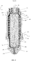
- the swirl ring 102 has a set of radially spaced gas flow openings 136 configured to impart a tangential velocity component to a gas flow for the plasma arc torch, causing the gas flow to swirl. This swirl creates a vortex that constricts the arc and stabilizes the position of the arc on the insert 142.
- the sealing device 150 such as an o-ring, can be located on an external surface of the swirl ring 102 at its proximal end 112 to engage an internal surface of the plasma arc torch body (not shown) when the the cartridge 100 is installed into the plasma arc torch body.
- the sealing device 150 is configured to provide a leak-proof seal of fluids (e.g., gases) between the cartridge 100 and the plasma arc torch body at that location.
- each of the retention surfaces/elements 216, 230 of FIGS. 4a and b simplifies alignment of the parts in the cartridge 100 in comparison to an operator having to perform alignment of individual components without any structural guidance.
- the locking of the swirl ring 102 to the nozzle 108 at the interface 118 via the retention element 216 aligns the two components relative to each other and further retains the electrode 104 in the chamber formed by the locking of the swirl ring 102 and the nozzle 108.
- the inner wall of the swirl ring 102 can radially align the electrode 104 such that there is a relatively small gap between the inner wall of the swirl ring 102 and the radial fins 114 of the electrode 104, thereby limiting a radial motion of the electrode 104.
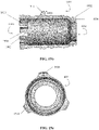
- Width W represents the curved axial width of each gas flow opening 136 (only one gas flow opening is shown).
- Length R represents the average distance (radius) between the center of the electrode 104 and the radius of the annular space between the exterior of the electrode body and the inner wall of the swirl ring 102, as measured from the shared center 602. In some cases, the W/R ratio is less than about 0.5. This value allows a gas flow entering a gas flow opening 136 to impinge somewhat perpendicularly on surface of the electrode 104, increasing gas turbulence and enhancing electrode cooling.
- the power supply provides a pilot arc current to the end cap 106 and the pilot arc current is passed to the electrode 104 through the resilient element 122 that biases the electrode 104 against nozzle 108.
- the resilient element 122 urges the electrode 104 into abutting relation with the nozzle 108, there is an absence of physical contact and electrical communication between the contact surface 310 of the end cap 106 and the corresponding contact surface 128 of the electrode 104.
- the resilient element 122 can be configured to pass substantially all of the pilot arc current from the end cap 106 to the electrode 104.
- the resilient element 122 is formed from a material that facilitates both carrying an electrical current and dissipating thermal heat associated with the current to prevent the resilient element 122 from melting.
- the material of the resilient element 122 can be selected based on the current rating of the material.
- the resilient element 122 comprises a helical compression spring, wire, or metal strip.
- different types of resilient element 122 configurations are described in U.S. Serial No. 13/344,860, assigned to Hypertherm, Inc. , of Hanover, New Hampshire.
- the resilient element 122 is inserted into the end cap 106 and housed in the tunnel portion 302 of the end cap 106 prior to affixing the end cap to the swirl ring 102 or 702.
- the sealing device 150 such as in the form of an o-ring, can be located on an external surface of the swirl ring 102 or 702 at its proximal end 112 to engage an internal surface of the plasma arc torch body (not shown) when the the cartridge 100 is installed into the plasma arc torch body.
- the nozzle 1010 can be a part of the inner component 1004 of the cartridge 1000 in FIG. 10 .
- the nozzle 1010 can define, in relation to the electrode 1008, a plasma chamber 1040.
- the nozzle 1010 is substantially the same as the nozzle 108 of FIG. 3 .
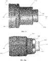
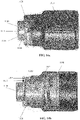
- FIG. 17 shows another exemplary configuration of the nozzle 1010 of the cartridge 1000 of FIG. 10 .
- the nozzle 1010 defines a distal portion 1704, a middle portion 1705, and a proximal portion 1706 along the longitudinal axis A.
- the nozzle 1010 can include a retention feature at the proximal portion 1706, such as an indent 1702 with an inner surface 1702a and an outer surface 1702b, configured to connect the nozzle 1010 to the distal end of the swirl ring 1007 at the interface 1021 (as shown in FIG. 10 ).
- a retention feature at the proximal portion 1706 such as an indent 1702 with an inner surface 1702a and an outer surface 1702b, configured to connect the nozzle 1010 to the distal end of the swirl ring 1007 at the interface 1021 (as shown in FIG. 10 ).
- the distal end of the swirl ring 1007 can be inserted into the indent 1702, and at least one of the inner surface 1702a or the outer surface 1702b of the indent 1702 can be crimped against a groove on the distal end of the swirl ring 1007 to secure the two components together.
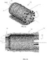
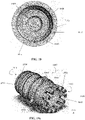
- each fin 1914 has a radial length 1916 that can be less than or equal to the radial distance between the external surface of the swirl ring 1007 (i.e., without the fins 1914) and the inner surface of the retaining cap 1014 when the swirl ring 1007 is centered within the retaining cap 1014.
- the fins 1914 can have substantially uniform dimensions.
- the fins 1914 can be a plurality of protrusions spaced apart at regular or non-regular intervals around an external circumference of the swirl ring 1007. The radial spacing between the fins 1914 allows gas to flow therethrough.
- each fin 1914 can be constructed such that there is a clearance between the fin 1914 and the corresponding inner sidewall of the retaining cap 1014 when the swirl ring 1007 is centered within the retaining cap 1014 to allow a gas flow therethrough.
- the fins 1914 can be located on other components of the cartridge 1000 to accomplish the same radial alignment function.
- the fins 1914 can be disposed in an internal surface of the outer component 1002, such as on an internal surface of the retaining cap 1014, to radially align the inner and outer components upon engagement.
- the fins 1914 comprise a mechanism (not shown) for securing the swirl ring 1007 to the retaining cap 1014 via, for example, snap fit. This connection can replace the securement mechanism between the nozzle 1010 and the swirl ring 1007 at the interface 1021.
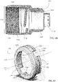
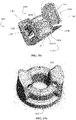
- the crown 1006 is a part of the inner component 1004 of the cartridge 1000 in FIG. 10 .
- the crown 1006 is substantially the same as the end cap 106 illustrated in FIGS. 7a and 7b .
- FIGS. 20a and b are exemplary configurations of the crown 1006 of the cartridge 1000 of FIG. 10 .
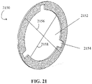
- the spacer 2150 can be a thin, substantially circular disk with a circular opening 2152 disposed in the center that is configured to surround a circumference of an external surface of the nozzle 1010 at its middle portion 1705.
- the spacer 2150 can be dimensioned such that (i) its outer diameter 2156 is about the same as or smaller than the interior diameter of the middle portion 1107 of the retaining cap 1014, but greater than that of the distal portion 1106 of the retaining cap 1014; and (ii) the diameter 2158 of the circular opening 2152 is same as or greater than that of the middle portion 1705 of the nozzle 1010, but less than that of the proximal portion 1706 of the nozzle 1010.
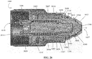
- the plasma chamber flow 2606 can exit the plasma chamber 1040 through a nozzle exit orifice of the nozzle 1010 and the shield exit orifice 1506 of the shield 1012.
- the vent flow 2607 is adapted to travel in a reverse direction to the proximal end 1018 of the outer component 1002 and exit the cartridge 1000 through the vent hole 2016 in the crown 1006.
- the electrode 1008 is housed in the chamber formed by the coupling of the nozzle 1010 to the distal end 1910 of the swirl ring 1007.
- the nozzle 1010 can be securely affixed to the swirl ring 1007 (e.g., via crimping). This interconnection secures the electrode 1008 within the inner component 1002 while the inner wall of the swirl ring axially aligns the electrode 1008 about the longitudinal axis A with respect to the nozzle 1010 such that the electrode 1008 is limited in its axial motion.
- the resilient element 1026 is inserted into the swirl ring 1007 from its proximal end 1912 until it contacts the relatively flat proximal end of the electrode 1008 within the swirl ring 1007.
- the optional spacer 2150 can be first disposed into the substantially hollow body of the outer component 1002 from the proximal end 1206 of the cap sleeve 1016.
- the spacer 2150 can distally advance within the hollow body of the outer component 1002 until it reaches the distal end of the middle portion 1107 of the retaining cap 1014 and cannot advance further to move into the distal portion 1106 of the retaining cap 1014.
- the spacer 2150 is adapted to fit around and radially align with an interior circumference of the middle portion 1107 of the retaining cap 1014.
- the inner component 1004 can also be disposed into the hollow body of the outer component 1002 from the proximal end 1206 of the cap sleeve 1016.
Landscapes
- Engineering & Computer Science (AREA)
- Physics & Mathematics (AREA)
- Plasma & Fusion (AREA)
- Spectroscopy & Molecular Physics (AREA)
- Mechanical Engineering (AREA)
- Plasma Technology (AREA)
Claims (12)
- Verbrauchbare Kartusche (1000) für einen Plasmalichtbogenbrenner, wobei die verbrauchbare Kartusche umfasst:eine Außenkomponente (1002), die einen im Wesentlichen hohlen Körper einschließt;und gekennzeichnet ist durch:eine Innenkomponente (1004) mit einem vorderen Anteil und einem hinteren Anteil, wobei die Innenkomponente eine Krone (1006), eine Elektrode (1008) und einen Wirbelring (1007) einschließt, wobei der Wirbelring (1007) die Elektrode (1008) teilweise umgibt und gleitfähig mit dieser in Eingriff ist, und die Krone (1006) an ein proximales Ende des Wirbelrings (1007) gekoppelt ist, wobei die Innenkomponente einschließlich des Wirbelrings und der Krone im Wesentlichen innerhalb des hohlen Körpers der Außenkomponente angeordnet ist, wobei mindestens ein Anteil der Innenkomponente von dem hohlen Körper der Außenkomponente umgeben ist; undeinen erhabenen Anteil (2002), der sich (i) von der Krone der Innenkomponente oder (ii) von dem Wirbelring der Innenkomponente hinter der Krone erstreckt, wobei der erhabene Anteil ausgestaltet ist, um einen verbrauchbaren Sensor innerhalb des Plasmalichtbogenbrenners zu kontaktieren und diesen zu aktivieren, wenn die verbrauchbare Kartusche auf einem Brennerkopf installiert wird.
- Verbrauchbare Kartusche nach Anspruch 1, wobei die Krone (1006) einen im Wesentlichen hohlen Körper (2000) umfasst, der ein proximales Ende (2020) und ein distales Ende (2022) definiert und den erhabenen Anteil (2002) und eine versenkte Mitte (2004) einschließt,
- Verbrauchbare Kartusche nach Anspruch 1, wobei der erhabene Anteil einen Lippenanteil (1934) umfasst oder ein solcher ist.
- Verbrauchbare Kartusche nach Anspruch 3, wobei die Krone (1006) eine Öffnung umfasst, die sich von einer Innenfläche zu einer Außenfläche der Krone erstreckt.
- Verbrauchbare Kartusche nach Anspruch 4, wobei der erhabene Anteil sich proximal in eine Öffnung in der Krone (1006) hinein und durch diese hindurch erstreckt, um den verbrauchbaren Sensor in dem Brenner zu kontaktieren und zu aktivieren.
- Verfahren zum Montieren eines Plasmalichtbogenbrenners zu dessen Betrieb, wobei der Plasmalichtbogenbrenner eine verbrauchbare Kartusche (1000) umfasst, die eine Außenkomponente (1002) und eine Innenkomponente (1004) einschließt,
und dadurch gekennzeichnet ist, dass die Außenkomponente (1002) der Kartusche (1000) einen im Wesentlichen hohlen Körper einschließt und die Innenkomponente (1004) der Kartusche (1000) eine Krone, eine Elektrode und einen Wirbelring einschließt, wobei das Verfahren des Weiteren durch die folgenden Schritte gekennzeichnet ist:Bereitstellen eines erhabenen Anteils, der sich (i) von einer Krone der Innenkomponente oder (ii) von einem Wirbelring der Innenkomponente hinter einer Krone der verbrauchbaren Kartusche erstreckt; undInstallieren der Kartusche in einem Plasmalichtbogenbrenner, wobei der erhabene Anteil einen verbrauchbaren Sensorschalter aktiviert, um eine Anwesenheit der Kartusche abzufühlen. - Verfahren nach Anspruch 6, des Weiteren umfassend:Absenken des verbrauchbaren Sensors durch den erhabenen Anteil; undHerstellen eines elektrischen Stromflusspfads von einer Leistungsquelle durch den Brenner hindurch.
- Verfahren nach Anspruch 6 oder Anspruch 7, wobei der Wirbelring die Elektrode teilweise umgibt und gleitfähig mit ihr in Eingriff ist und die Krone an ein proximales Ende des Wirbelrings gekoppelt ist.
- Verfahren nach einem der Ansprüche 6 bis 8, wobei die Krone (1006) einen im Wesentlichen hohlen Körper (2000) umfasst, der ein proximales Ende (2020) und ein distales Ende (2022) definiert und den erhabenen Anteil (2002) und eine versenkte Mitte (2004) einschließt,
- Verfahren nach einem der Ansprüche 6 bis 8, wobei der erhabene Anteil einen Lippenanteil (1934) umfasst oder ein solcher ist.
- Verfahren nach einem der Ansprüche 6 bis 10, wobei die Krone (1006) eine Öffnung umfasst, die sich von einer Innenfläche zu einer Außenfläche der Krone erstreckt.
- Verfahren nach Anspruch 11, wobei der erhabene Anteil des Wirbelrings (1007) sich proximal in eine Öffnung in der Krone (1006) hinein und durch diese hindurch erstreckt, um den verbrauchbaren Sensor in dem Brenner zu kontaktieren und zu aktivieren.
Applications Claiming Priority (3)
| Application Number | Priority Date | Filing Date | Title |
|---|---|---|---|
| US14/824,946 US10582605B2 (en) | 2014-08-12 | 2015-08-12 | Cost effective cartridge for a plasma arc torch |
| PCT/US2016/017799 WO2017027065A1 (en) | 2014-08-12 | 2016-02-12 | Cost effective cartridge for a plasma arc torch |
| EP16705889.0A EP3334556B1 (de) | 2015-08-12 | 2016-02-12 | Verbrauchskassette für einen plasmabogenbrenner, verfahren zum zusammenbau einer solchen verbrauchskassette, und verfahren zum installieren einer verbrauchskassette in einen plasmabogenbrenner |
Related Parent Applications (2)
| Application Number | Title | Priority Date | Filing Date |
|---|---|---|---|
| EP16705889.0A Division-Into EP3334556B1 (de) | 2014-08-12 | 2016-02-12 | Verbrauchskassette für einen plasmabogenbrenner, verfahren zum zusammenbau einer solchen verbrauchskassette, und verfahren zum installieren einer verbrauchskassette in einen plasmabogenbrenner |
| EP16705889.0A Division EP3334556B1 (de) | 2014-08-12 | 2016-02-12 | Verbrauchskassette für einen plasmabogenbrenner, verfahren zum zusammenbau einer solchen verbrauchskassette, und verfahren zum installieren einer verbrauchskassette in einen plasmabogenbrenner |
Publications (2)
| Publication Number | Publication Date |
|---|---|
| EP3473370A1 EP3473370A1 (de) | 2019-04-24 |
| EP3473370B1 true EP3473370B1 (de) | 2022-03-30 |
Family
ID=62092367
Family Applications (2)
| Application Number | Title | Priority Date | Filing Date |
|---|---|---|---|
| EP16705889.0A Active EP3334556B1 (de) | 2014-08-12 | 2016-02-12 | Verbrauchskassette für einen plasmabogenbrenner, verfahren zum zusammenbau einer solchen verbrauchskassette, und verfahren zum installieren einer verbrauchskassette in einen plasmabogenbrenner |
| EP18194353.1A Active EP3473370B1 (de) | 2015-08-12 | 2016-02-12 | Verbrauchbare kartusche für einen plasmalichtbogenbrenner, und verfahren zum verbinden eines plasmalichtbogenbrenner für seine verwendung |
Family Applications Before (1)
| Application Number | Title | Priority Date | Filing Date |
|---|---|---|---|
| EP16705889.0A Active EP3334556B1 (de) | 2014-08-12 | 2016-02-12 | Verbrauchskassette für einen plasmabogenbrenner, verfahren zum zusammenbau einer solchen verbrauchskassette, und verfahren zum installieren einer verbrauchskassette in einen plasmabogenbrenner |
Country Status (2)
| Country | Link |
|---|---|
| EP (2) | EP3334556B1 (de) |
| KR (1) | KR102519617B1 (de) |
Cited By (1)
| Publication number | Priority date | Publication date | Assignee | Title |
|---|---|---|---|---|
| IT202300010248A1 (it) | 2023-05-19 | 2024-11-19 | Tec Mo S R L | Adattatore per elementi consumabili di una torcia al plasma |
Families Citing this family (7)
| Publication number | Priority date | Publication date | Assignee | Title |
|---|---|---|---|---|
| US11783138B2 (en) * | 2012-04-04 | 2023-10-10 | Hypertherm, Inc. | Configuring signal devices in thermal processing systems |
| US12275082B2 (en) | 2013-11-13 | 2025-04-15 | Hypertherm, Inc. | Consumable cartridge for a plasma arc cutting system |
| US12521905B2 (en) | 2014-03-07 | 2026-01-13 | Hypertherm, Inc. | Liquid pressurization pump and systems with data storage |
| AU2015301727B2 (en) | 2014-08-12 | 2020-05-14 | Hypertherm, Inc. | Cost effective cartridge for a plasma arc torch |
| MX2019009420A (es) | 2017-02-09 | 2019-10-02 | Hypertherm Inc | Anillo rotacional y elemento de contacto para un cartucho de antorcha de arco de plasma. |
| EP4351280A3 (de) * | 2018-11-07 | 2024-07-10 | Hypertherm, Inc. | Rahmen für eine kartusche für ein plasmalichtbogenschneidsystem, verfahren zum kühlen des plasmalichtbogenschneidsystems und verfahren zur herstellung des rahmens |
| US11839015B2 (en) | 2021-02-04 | 2023-12-05 | The Esab Group Inc. | Consumables for processing torches |
Citations (3)
| Publication number | Priority date | Publication date | Assignee | Title |
|---|---|---|---|---|
| US4940877A (en) * | 1989-09-15 | 1990-07-10 | Century Mfg. Co. | Parts in place torch structure |
| FR2700982A1 (fr) * | 1993-02-01 | 1994-08-05 | Soudure Autogene Francaise | Dispositif de sécurité électrique pour torche de coupage à plasma. |
| US6207923B1 (en) * | 1998-11-05 | 2001-03-27 | Hypertherm, Inc. | Plasma arc torch tip providing a substantially columnar shield flow |
Family Cites Families (2)
| Publication number | Priority date | Publication date | Assignee | Title |
|---|---|---|---|---|
| US6717096B2 (en) * | 2001-02-27 | 2004-04-06 | Thermal Dynamics Corporation | Dual mode plasma arc torch |
| US8089025B2 (en) * | 2007-02-16 | 2012-01-03 | Hypertherm, Inc. | Gas-cooled plasma arc cutting torch |
-
2016
- 2016-02-12 EP EP16705889.0A patent/EP3334556B1/de active Active
- 2016-02-12 KR KR1020187007138A patent/KR102519617B1/ko active Active
- 2016-02-12 EP EP18194353.1A patent/EP3473370B1/de active Active
Patent Citations (3)
| Publication number | Priority date | Publication date | Assignee | Title |
|---|---|---|---|---|
| US4940877A (en) * | 1989-09-15 | 1990-07-10 | Century Mfg. Co. | Parts in place torch structure |
| FR2700982A1 (fr) * | 1993-02-01 | 1994-08-05 | Soudure Autogene Francaise | Dispositif de sécurité électrique pour torche de coupage à plasma. |
| US6207923B1 (en) * | 1998-11-05 | 2001-03-27 | Hypertherm, Inc. | Plasma arc torch tip providing a substantially columnar shield flow |
Cited By (2)
| Publication number | Priority date | Publication date | Assignee | Title |
|---|---|---|---|---|
| IT202300010248A1 (it) | 2023-05-19 | 2024-11-19 | Tec Mo S R L | Adattatore per elementi consumabili di una torcia al plasma |
| WO2024241241A1 (en) | 2023-05-19 | 2024-11-28 | Tec.Mo S.R.L. | Adapter for consumable elements of a plasma torch |
Also Published As
| Publication number | Publication date |
|---|---|
| EP3334556B1 (de) | 2023-07-05 |
| KR102519617B1 (ko) | 2023-04-06 |
| KR20180040645A (ko) | 2018-04-20 |
| EP3334556A1 (de) | 2018-06-20 |
| EP3334556C0 (de) | 2023-07-05 |
| EP3473370A1 (de) | 2019-04-24 |
Similar Documents
| Publication | Publication Date | Title |
|---|---|---|
| US11991813B2 (en) | Cost effective cartridge for a plasma arc torch | |
| US12583051B2 (en) | Cost effective cartridge for a plasma arc torch | |
| EP3473370B1 (de) | Verbrauchbare kartusche für einen plasmalichtbogenbrenner, und verfahren zum verbinden eines plasmalichtbogenbrenner für seine verwendung | |
| US11432393B2 (en) | Cost effective cartridge for a plasma arc torch | |
| EP4223083A1 (de) | Kostengünstige kartusche für einen plasmalichtbogenbrenner | |
| EP3141090B1 (de) | Ersetzbare verschleisskartusche für lichtbogenplasmaschneidsystem | |
| JP7411646B2 (ja) | 交換可能な単一の消耗カートリッジ用のフレーム、その製造方法、及びプラズマアークトーチの冷却方法 | |
| EP4090138B1 (de) | Elektrode für eine verscheissbare kartusche eines plasmalichtbogenbrenners |
Legal Events
| Date | Code | Title | Description |
|---|---|---|---|
| PUAI | Public reference made under article 153(3) epc to a published international application that has entered the european phase |
Free format text: ORIGINAL CODE: 0009012 |
|
| STAA | Information on the status of an ep patent application or granted ep patent |
Free format text: STATUS: THE APPLICATION HAS BEEN PUBLISHED |
|
| AC | Divisional application: reference to earlier application |
Ref document number: 3334556 Country of ref document: EP Kind code of ref document: P |
|
| AK | Designated contracting states |
Kind code of ref document: A1 Designated state(s): AL AT BE BG CH CY CZ DE DK EE ES FI FR GB GR HR HU IE IS IT LI LT LU LV MC MK MT NL NO PL PT RO RS SE SI SK SM TR |
|
| AX | Request for extension of the european patent |
Extension state: BA ME |
|
| STAA | Information on the status of an ep patent application or granted ep patent |
Free format text: STATUS: REQUEST FOR EXAMINATION WAS MADE |
|
| 17P | Request for examination filed |
Effective date: 20191024 |
|
| RBV | Designated contracting states (corrected) |
Designated state(s): AL AT BE BG CH CY CZ DE DK EE ES FI FR GB GR HR HU IE IS IT LI LT LU LV MC MK MT NL NO PL PT RO RS SE SI SK SM TR |
|
| STAA | Information on the status of an ep patent application or granted ep patent |
Free format text: STATUS: EXAMINATION IS IN PROGRESS |
|
| 17Q | First examination report despatched |
Effective date: 20200409 |
|
| GRAP | Despatch of communication of intention to grant a patent |
Free format text: ORIGINAL CODE: EPIDOSNIGR1 |
|
| STAA | Information on the status of an ep patent application or granted ep patent |
Free format text: STATUS: GRANT OF PATENT IS INTENDED |
|
| INTG | Intention to grant announced |
Effective date: 20211022 |
|
| GRAS | Grant fee paid |
Free format text: ORIGINAL CODE: EPIDOSNIGR3 |
|
| GRAA | (expected) grant |
Free format text: ORIGINAL CODE: 0009210 |
|
| STAA | Information on the status of an ep patent application or granted ep patent |
Free format text: STATUS: THE PATENT HAS BEEN GRANTED |
|
| AC | Divisional application: reference to earlier application |
Ref document number: 3334556 Country of ref document: EP Kind code of ref document: P |
|
| AK | Designated contracting states |
Kind code of ref document: B1 Designated state(s): AL AT BE BG CH CY CZ DE DK EE ES FI FR GB GR HR HU IE IS IT LI LT LU LV MC MK MT NL NO PL PT RO RS SE SI SK SM TR |
|
| REG | Reference to a national code |
Ref country code: GB Ref legal event code: FG4D |
|
| REG | Reference to a national code |
Ref country code: CH Ref legal event code: EP |
|
| REG | Reference to a national code |
Ref country code: DE Ref legal event code: R096 Ref document number: 602016070660 Country of ref document: DE |
|
| REG | Reference to a national code |
Ref country code: AT Ref legal event code: REF Ref document number: 1478720 Country of ref document: AT Kind code of ref document: T Effective date: 20220415 |
|
| REG | Reference to a national code |
Ref country code: IE Ref legal event code: FG4D |
|
| REG | Reference to a national code |
Ref country code: LT Ref legal event code: MG9D |
|
| PG25 | Lapsed in a contracting state [announced via postgrant information from national office to epo] |
Ref country code: SE Free format text: LAPSE BECAUSE OF FAILURE TO SUBMIT A TRANSLATION OF THE DESCRIPTION OR TO PAY THE FEE WITHIN THE PRESCRIBED TIME-LIMIT Effective date: 20220330 Ref country code: RS Free format text: LAPSE BECAUSE OF FAILURE TO SUBMIT A TRANSLATION OF THE DESCRIPTION OR TO PAY THE FEE WITHIN THE PRESCRIBED TIME-LIMIT Effective date: 20220330 Ref country code: NO Free format text: LAPSE BECAUSE OF FAILURE TO SUBMIT A TRANSLATION OF THE DESCRIPTION OR TO PAY THE FEE WITHIN THE PRESCRIBED TIME-LIMIT Effective date: 20220630 Ref country code: LT Free format text: LAPSE BECAUSE OF FAILURE TO SUBMIT A TRANSLATION OF THE DESCRIPTION OR TO PAY THE FEE WITHIN THE PRESCRIBED TIME-LIMIT Effective date: 20220330 Ref country code: HR Free format text: LAPSE BECAUSE OF FAILURE TO SUBMIT A TRANSLATION OF THE DESCRIPTION OR TO PAY THE FEE WITHIN THE PRESCRIBED TIME-LIMIT Effective date: 20220330 Ref country code: BG Free format text: LAPSE BECAUSE OF FAILURE TO SUBMIT A TRANSLATION OF THE DESCRIPTION OR TO PAY THE FEE WITHIN THE PRESCRIBED TIME-LIMIT Effective date: 20220630 |
|
| REG | Reference to a national code |
Ref country code: NL Ref legal event code: MP Effective date: 20220330 |
|
| REG | Reference to a national code |
Ref country code: AT Ref legal event code: MK05 Ref document number: 1478720 Country of ref document: AT Kind code of ref document: T Effective date: 20220330 |
|
| PG25 | Lapsed in a contracting state [announced via postgrant information from national office to epo] |
Ref country code: LV Free format text: LAPSE BECAUSE OF FAILURE TO SUBMIT A TRANSLATION OF THE DESCRIPTION OR TO PAY THE FEE WITHIN THE PRESCRIBED TIME-LIMIT Effective date: 20220330 Ref country code: GR Free format text: LAPSE BECAUSE OF FAILURE TO SUBMIT A TRANSLATION OF THE DESCRIPTION OR TO PAY THE FEE WITHIN THE PRESCRIBED TIME-LIMIT Effective date: 20220701 Ref country code: FI Free format text: LAPSE BECAUSE OF FAILURE TO SUBMIT A TRANSLATION OF THE DESCRIPTION OR TO PAY THE FEE WITHIN THE PRESCRIBED TIME-LIMIT Effective date: 20220330 |
|
| PG25 | Lapsed in a contracting state [announced via postgrant information from national office to epo] |
Ref country code: NL Free format text: LAPSE BECAUSE OF FAILURE TO SUBMIT A TRANSLATION OF THE DESCRIPTION OR TO PAY THE FEE WITHIN THE PRESCRIBED TIME-LIMIT Effective date: 20220330 |
|
| PG25 | Lapsed in a contracting state [announced via postgrant information from national office to epo] |
Ref country code: SM Free format text: LAPSE BECAUSE OF FAILURE TO SUBMIT A TRANSLATION OF THE DESCRIPTION OR TO PAY THE FEE WITHIN THE PRESCRIBED TIME-LIMIT Effective date: 20220330 Ref country code: SK Free format text: LAPSE BECAUSE OF FAILURE TO SUBMIT A TRANSLATION OF THE DESCRIPTION OR TO PAY THE FEE WITHIN THE PRESCRIBED TIME-LIMIT Effective date: 20220330 Ref country code: RO Free format text: LAPSE BECAUSE OF FAILURE TO SUBMIT A TRANSLATION OF THE DESCRIPTION OR TO PAY THE FEE WITHIN THE PRESCRIBED TIME-LIMIT Effective date: 20220330 Ref country code: PT Free format text: LAPSE BECAUSE OF FAILURE TO SUBMIT A TRANSLATION OF THE DESCRIPTION OR TO PAY THE FEE WITHIN THE PRESCRIBED TIME-LIMIT Effective date: 20220801 Ref country code: ES Free format text: LAPSE BECAUSE OF FAILURE TO SUBMIT A TRANSLATION OF THE DESCRIPTION OR TO PAY THE FEE WITHIN THE PRESCRIBED TIME-LIMIT Effective date: 20220330 Ref country code: EE Free format text: LAPSE BECAUSE OF FAILURE TO SUBMIT A TRANSLATION OF THE DESCRIPTION OR TO PAY THE FEE WITHIN THE PRESCRIBED TIME-LIMIT Effective date: 20220330 Ref country code: AT Free format text: LAPSE BECAUSE OF FAILURE TO SUBMIT A TRANSLATION OF THE DESCRIPTION OR TO PAY THE FEE WITHIN THE PRESCRIBED TIME-LIMIT Effective date: 20220330 |
|
| PG25 | Lapsed in a contracting state [announced via postgrant information from national office to epo] |
Ref country code: IS Free format text: LAPSE BECAUSE OF FAILURE TO SUBMIT A TRANSLATION OF THE DESCRIPTION OR TO PAY THE FEE WITHIN THE PRESCRIBED TIME-LIMIT Effective date: 20220730 Ref country code: AL Free format text: LAPSE BECAUSE OF FAILURE TO SUBMIT A TRANSLATION OF THE DESCRIPTION OR TO PAY THE FEE WITHIN THE PRESCRIBED TIME-LIMIT Effective date: 20220330 |
|
| REG | Reference to a national code |
Ref country code: DE Ref legal event code: R097 Ref document number: 602016070660 Country of ref document: DE |
|
| PG25 | Lapsed in a contracting state [announced via postgrant information from national office to epo] |
Ref country code: DK Free format text: LAPSE BECAUSE OF FAILURE TO SUBMIT A TRANSLATION OF THE DESCRIPTION OR TO PAY THE FEE WITHIN THE PRESCRIBED TIME-LIMIT Effective date: 20220330 |
|
| PLBE | No opposition filed within time limit |
Free format text: ORIGINAL CODE: 0009261 |
|
| STAA | Information on the status of an ep patent application or granted ep patent |
Free format text: STATUS: NO OPPOSITION FILED WITHIN TIME LIMIT |
|
| 26N | No opposition filed |
Effective date: 20230103 |
|
| PG25 | Lapsed in a contracting state [announced via postgrant information from national office to epo] |
Ref country code: SI Free format text: LAPSE BECAUSE OF FAILURE TO SUBMIT A TRANSLATION OF THE DESCRIPTION OR TO PAY THE FEE WITHIN THE PRESCRIBED TIME-LIMIT Effective date: 20220330 |
|
| P01 | Opt-out of the competence of the unified patent court (upc) registered |
Effective date: 20230517 |
|
| PG25 | Lapsed in a contracting state [announced via postgrant information from national office to epo] |
Ref country code: MC Free format text: LAPSE BECAUSE OF FAILURE TO SUBMIT A TRANSLATION OF THE DESCRIPTION OR TO PAY THE FEE WITHIN THE PRESCRIBED TIME-LIMIT Effective date: 20220330 |
|
| REG | Reference to a national code |
Ref country code: CH Ref legal event code: PL |
|
| REG | Reference to a national code |
Ref country code: BE Ref legal event code: MM Effective date: 20230228 |
|
| PG25 | Lapsed in a contracting state [announced via postgrant information from national office to epo] |
Ref country code: LU Free format text: LAPSE BECAUSE OF NON-PAYMENT OF DUE FEES Effective date: 20230212 Ref country code: LI Free format text: LAPSE BECAUSE OF NON-PAYMENT OF DUE FEES Effective date: 20230228 Ref country code: CH Free format text: LAPSE BECAUSE OF NON-PAYMENT OF DUE FEES Effective date: 20230228 |
|
| REG | Reference to a national code |
Ref country code: IE Ref legal event code: MM4A |
|
| PG25 | Lapsed in a contracting state [announced via postgrant information from national office to epo] |
Ref country code: IE Free format text: LAPSE BECAUSE OF NON-PAYMENT OF DUE FEES Effective date: 20230212 |
|
| PG25 | Lapsed in a contracting state [announced via postgrant information from national office to epo] |
Ref country code: BE Free format text: LAPSE BECAUSE OF NON-PAYMENT OF DUE FEES Effective date: 20230228 |
|
| PGFP | Annual fee paid to national office [announced via postgrant information from national office to epo] |
Ref country code: PL Payment date: 20250131 Year of fee payment: 10 Ref country code: CZ Payment date: 20250206 Year of fee payment: 10 |
|
| PG25 | Lapsed in a contracting state [announced via postgrant information from national office to epo] |
Ref country code: CY Free format text: LAPSE BECAUSE OF FAILURE TO SUBMIT A TRANSLATION OF THE DESCRIPTION OR TO PAY THE FEE WITHIN THE PRESCRIBED TIME-LIMIT; INVALID AB INITIO Effective date: 20160212 |
|
| PG25 | Lapsed in a contracting state [announced via postgrant information from national office to epo] |
Ref country code: HU Free format text: LAPSE BECAUSE OF FAILURE TO SUBMIT A TRANSLATION OF THE DESCRIPTION OR TO PAY THE FEE WITHIN THE PRESCRIBED TIME-LIMIT; INVALID AB INITIO Effective date: 20160212 |
|
| PGFP | Annual fee paid to national office [announced via postgrant information from national office to epo] |
Ref country code: GB Payment date: 20260219 Year of fee payment: 11 |
|
| PGFP | Annual fee paid to national office [announced via postgrant information from national office to epo] |
Ref country code: DE Payment date: 20260218 Year of fee payment: 11 |
|
| PGFP | Annual fee paid to national office [announced via postgrant information from national office to epo] |
Ref country code: IT Payment date: 20260224 Year of fee payment: 11 |
|
| PGFP | Annual fee paid to national office [announced via postgrant information from national office to epo] |
Ref country code: FR Payment date: 20260218 Year of fee payment: 11 |
|
| PGFP | Annual fee paid to national office [announced via postgrant information from national office to epo] |
Ref country code: TR Payment date: 20260204 Year of fee payment: 11 |