EP3472513B1 - A bottom-supported boiler - Google Patents
A bottom-supported boiler Download PDFInfo
- Publication number
- EP3472513B1 EP3472513B1 EP16735668.2A EP16735668A EP3472513B1 EP 3472513 B1 EP3472513 B1 EP 3472513B1 EP 16735668 A EP16735668 A EP 16735668A EP 3472513 B1 EP3472513 B1 EP 3472513B1
- Authority
- EP
- European Patent Office
- Prior art keywords
- boiler
- supported
- vertical columns
- accordance
- pressure body
- Prior art date
- Legal status (The legal status is an assumption and is not a legal conclusion. Google has not performed a legal analysis and makes no representation as to the accuracy of the status listed.)
- Active
Links
Images


Classifications
-
- F—MECHANICAL ENGINEERING; LIGHTING; HEATING; WEAPONS; BLASTING
- F22—STEAM GENERATION
- F22B—METHODS OF STEAM GENERATION; STEAM BOILERS
- F22B37/00—Component parts or details of steam boilers
- F22B37/02—Component parts or details of steam boilers applicable to more than one kind or type of steam boiler
- F22B37/24—Supporting, suspending or setting arrangements, e.g. heat shielding
- F22B37/242—Supporting, suspending or setting arrangements, e.g. heat shielding for bottom supported water-tube steam generators
Definitions
- the present invention relates to a bottom-supported boiler in accordance with the preamble of claim 1. More particularly, the invention relates to a bottom-supported boiler comprising a boiler pressure body, such as a furnace, a convection cage, an empty pass, a solid separator, or a horizontal pass, and a construction for supporting the boiler pressure body.
- a boiler pressure body such as a furnace, a convection cage, an empty pass, a solid separator, or a horizontal pass
- a construction for supporting the boiler pressure body such as a furnace, a convection cage, an empty pass, a solid separator, or a horizontal pass.
- Relatively large boiler pressure bodies such as tube walled furnaces
- top-supported i.e. so that the boiler pressure body is arranged to hang from a rigid supporting structure.
- Relatively small boiler pressure bodies are conventionally arranged as bottom-supported, wherein vertical load of the boiler pressure body is balanced solely by a support construction arranged below the boiler pressure body.
- the main difference between top-supported and bottom-supported constructions is that when the temperature of the boiler pressure body increases, thermal expansion of a top-supported boiler pressure body takes place mainly downwards whereas in a bottom-supported boiler pressure body thermal expansion takes place mainly upwards.
- Bottom-supported boiler pressure bodies are generally simpler and economically more advantageous than top-supported boiler pressure bodies, because they do not require a separate supporting structure.
- bottom-supported construction is that the walls have to be strong enough to carry the vertical compression load of the boiler pressure body. Therefore bottom-supported construction is conventionally applied only for relatively small boiler pressure bodies, such as furnaces of power boilers with a capacity of less than 40 MWe.
- US Patent No. 3,280,800 discloses a conventional bottom-supported boiler, comprising a self-standing tube-walled furnace and a boiler bank downstream the furnace, supported by a downcomer.
- Bottom support for the furnace is provided by a plurality of support members mounted atop pedestals and adapted to engage, either fixedly or slidably, headers of the wall tubes.
- US Patent No. 3,927,714 discloses a bottom-supported boiler comprising a frame of vertical down pipes and return pipes connected by manifolds and headers, and provides from below vertical support to vertical water tubes connected between the manifolds and headers.
- DE Patent No. 27 48 650 discloses a bottom-supported boiler comprising in U-form bent evaporation tubes within the boiler, in which the outermost portions of the evaporation tubes are connected to an opposite water tube wall so as to provide vertical support for the evaporation tubes.
- Documents DE1526931 A1 and US2016/123574 A1 disclose further bottom-supported boilers.
- An object of the present invention is to provide a bottom-supported boiler with an improved support construction for vertical water tube walls of a boiler pressure body.
- the present invention provides a bottom-supported boiler comprising a boiler pressure body having a rectangular horizontal cross section formed by joining four planar water tube walls pairwise together so as to form four corner sections, and a support construction, wherein the support construction comprises four vertical columns vertically supported to the ground, the vertical columns being arranged outside the boiler pressure body so that adjacent to each of the corner sections is arranged one of the four vertical columns, wherein each of the vertical columns is attached to the respective corner section.
- vertical loads such as gravitational forces and forces caused by seismic loads and direct wind loads
- the four vertical columns advantageously solely by the four vertical columns.
- the present invention also minimizes the need to use especially large diameter thick-walled tubes, as required if conventional solution is applied to relatively large boilers, to obtain sufficient stiffness and strength of the tube walls.
- the four vertical columns are preferably substantially as high as the boiler pressure body, but in some applications they may alternatively have a smaller height than the boiler pressure body. Thereby, the four vertical columns are preferably attached to the respective corner sections in a region having a height of at least 30 % of the height of the boiler pressure body, even more preferably a height of at least 60 % of the height of the boiler pressure body. In some cases, when the vertical columns have also other functions than just supporting the pressure body, for example supporting a steam drum, the vertical columns, or at least some of them, may extend even higher than the boiler pressure body. When vertical columns as high as, or higher than, the boiler pressure body are used, the four vertical columns are advantageously attached to the respective corner sections in a region having a height that substantially equals to the height of the boiler pressure body.
- each of the four vertical columns is attached to the respective corner section by a continuous metal strip that provides, in vertical direction, a rigid joint.
- the metal strip is advantageously dimensioned so that it provides, in addition to the desired rigidity, also so good thermal contact between the corner section and the vertical column that they stay in substantially equal temperature.
- the attaching is advantageously made with a continuous weld to a corner fin between outermost water tubes of the water tube walls forming the corner section.
- Thermal expansion of the planar water tube walls of the boiler pressure body takes place mainly upwards. However, thermal expansion generally takes place, usually to a smaller amount, also in horizontal direction. According to an advantageous embodiment of the present invention, horizontal thermal expansion is taken into account by supporting at least some of the four vertical columns to the ground by using conventional sliding elements. In such a case, most preferably, all four vertical columns are supported by a sliding element, and horizontal movements of the boiler pressure body are prevented by suitable guiding elements. It is, however, also possible that one of the vertical columns is fixed to the ground or foundation of the boiler, and the other three vertical columns are supported by a sliding element.
- the four vertical columns are supported to the ground by a support steel construction below the vertical columns.
- the support steel construction advantageously comprises a second vertical steel column below each of the four vertical columns.
- the support steel construction is advantageously substantially rigid.
- the support steel construction is designed flexible to render sufficient bending of the support steel construction possible, to allow horizontal thermal expansion of the planar water tube walls without sliding elements between the vertical columns and the support steel construction.
- the support steel construction comprises below the boiler pressure body an upper portion that is flexible to allow horizontal thermal expansion of the planar water tube walls without sliding elements, and a rigid lower portion, such as foundations of the boiler.
- At least one, preferably each, of the four vertical columns is a boiler pipe.
- the boiler pipes are downcomer pipes of the boiler, but in some applications they could also be, for example, steam pipes.
- the downcomer pipes By using the downcomer pipes as the vertical columns, the need for special supporting of the downcomer pipes is minimized. Because the water in the downcomer pipes is nearly in the same temperature as the water in the water wall tubes, there is not any significant thermal stress between the water tube walls and the downcomer pipes.
- At least one of the multiple vertical columns is a not a boiler pipe.
- Such vertical column can be, for example, a separate hollow vertical beam with a square cross section.
- Such separate hollow vertical beams which are dedicated to the use as the vertical columns, have the advantage that their sizes can be more freely selected, and their sizes can even change with the elevation.
- minimizing temperature difference between the water tube walls and the vertical columns has to be ensured by using especially good thermal conductivity providing metal strips between the water tube walls and the vertical columns.
- each of the four vertical columns no matter of being, for example, a boiler pipe or a hollow vertical beam, is preferably arranged inside a common thermal insulation with the boiler pressure body.
- the present invention is especially applicable when the boiler is a bottom-supported fluidized bed boiler, such as bubbling bed boiler, or PC boiler.
- the boiler pressure body is one of a furnace, a convection cage in connection with a furnace, an empty pass in connection with a furnace, a solid separator in connection with a furnace or a horizontal pass in connection with a furnace.
- the present invention also renders possible an especially straight forward design of the boiler, clearly faster erection of the boiler than by using conventional methods, and a remarkable reduction in the quantities of the required steel structures.
- FIG. 1 schematically illustrates a side view of a bottom-supported bubbling bed boiler 10, representing an embodiment of the present invention.
- the bubbling bed boiler 10 is self-standing and supported to the ground 12 via a rigid support steel construction 14 arranged below the boiler.
- thermal expansion of the boiler takes place upwards from the support steel construction 14.
- the latter is taken into account by having the boiler at least partially supported on the support steel construction 14 by suitable sliding support elements 18.
- FIG. 1 shows one sliding support element 18 and one fixed support element 20, but it is also possible that the boiler is supported on the support steel construction solely by sliding support elements.
- the boiler 10 comprises a boiler pressure body 22 made of four planar water tube walls 24, only one of which can be seen in FIG. 1 .
- the water tube walls 24 are formed in a conventional manner of vertical water tubes 38 and fins welded between the water tubes.
- the water tube walls 24 are pairwise joined together so as to form a rectangular horizontal cross section, having four corner sections 26.
- FIG. 1 shows also a steam drum 42, from where circulating water is conveyed in a conventional manner through downcomer pipes 44, 46 and lower headers 28, only one of which is seen in FIG. 1 , to the water tubes 38 of the water tube walls 24.
- the steam drum is advantageously arranged on top of downcomer pipes 44 so as to be supported by the downcomer pipes 44. Water is evaporated in the water tubes 38, and a mixture of steam and water is conveyed through an upper header 48 and steam pipes 50 back to the steam drum 42 in order to provide steam for further use. Due to the circulating water, thermal expansion of the downcomer pipes 44, 46 is nearly as large as that of the tube walls 24 of the boiler pressure body 22.
- the boiler pressure body 22 is not supported on the support steel construction 14 in a conventional manner at multiple points of the lower headers 28 of the water tube walls 24, but by using four vertical columns 30 arranged outside the boiler pressure body 22.
- the vertical columns are defined by the downcomer pipes 44, 46.
- the vertical columns can be other boiler pipes than downcomer pipes, such as steam pipes.
- the vertical columns may be other columns than boiler pipes, for example hollow vertical beams.
- each of the corner sections 26 adjacent to each of the corner sections 26 is arranged one of the four vertical columns 30.
- Each of the vertical columns 30 is in vertical direction rigidly attached to the respective corner section 24 by a vertically extending metal strip 32.
- the metal strips are advantageously dimensioned so as to provide sufficient thermal conductivity between the corner sections 26 and the respective vertical columns 30.
- the temperature difference between corner sections 26 and the vertical columns 30 has to be in any operating condition relatively small in order to avoid unnecessary thermal fatigue.
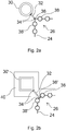
- FIGS. 2a and 2b show more in details two examples of attaching a vertical column 30, 30' to the corner section 26 of two water tube walls 24.
- the vertical column 30 is a downcomer pipe, or another relatively thick walled boiler pipe.
- the vertical column 30' is a hollow vertical beam with a square cross sectional shape.
- the metal strips 32 are preferably attached by continuous welds 34 to the vertical columns 30, 30' and to a corner fin 36, 36' between outermost water tubes 38, 38' of the water tube walls 24 forming the corner section 26.
- the corner fin 36 makes a corner
- the corner fin 36' in FIG. 2b is beveled.
- FIGS. 2a and 2b the metal strip 32 is in 45 degrees angle to the water tube walls 24, but in practice the metal strip can alternatively be parallel to a water tube wall, or in other suitable angle to the walls.
- FIG. 2b schematically shows also insulation 40 surrounding both the water tube walls 24 and the vertical column 30', which is necessary to maintain the vertical column and the water tube walls 24 at a uniform temperature. It should be understood that corresponding insulation is to be used also in the embodiment of FIG. 2a .
- FIG. 3 shows another embodiment of the present invention that differs from the embodiment of FIG. 1 only in that instead of being rigid, the support steel construction 14' arranged below the boiler pressure body 22 is designed flexible. Thereby, the flexible support steel construction 14' renders sufficient bending of the support steel construction possible, to allow horizontal thermal expansion of the planar water tube walls without using sliding elements between the vertical columns and the support steel construction.
- the support steel construction comprises second vertical columns 52 below each of the above described vertical columns 30 adjacent to the corner sections 26.
- the flexible support steel construction may also comprise diagonal braces 54 from the bottom portion of the second vertical columns 52 to a central section of a horizontal beam 16 in the upper portion of the support steel construction 14'. It should be noted that in the embodiment of FIG. 3 the second vertical columns 52 and diagonal braces 54 are connected to the insulated, hot vertical columns 30 and horizontal beams 16', respectively, whereas in the embodiment of FIG. 1 , the support steel construction 14 comprises an upper horizontal 16 beam that is nearly at the ambient temperature.
Landscapes
- Engineering & Computer Science (AREA)
- Physics & Mathematics (AREA)
- Thermal Sciences (AREA)
- Mechanical Engineering (AREA)
- General Engineering & Computer Science (AREA)
- Fluidized-Bed Combustion And Resonant Combustion (AREA)
- Sewage (AREA)
- Buildings Adapted To Withstand Abnormal External Influences (AREA)
- Supports For Pipes And Cables (AREA)
Description
- The present invention relates to a bottom-supported boiler in accordance with the preamble of claim 1. More particularly, the invention relates to a bottom-supported boiler comprising a boiler pressure body, such as a furnace, a convection cage, an empty pass, a solid separator, or a horizontal pass, and a construction for supporting the boiler pressure body.
- Relatively large boiler pressure bodies, such as tube walled furnaces, are generally arranged top-supported, i.e. so that the boiler pressure body is arranged to hang from a rigid supporting structure. Relatively small boiler pressure bodies are conventionally arranged as bottom-supported, wherein vertical load of the boiler pressure body is balanced solely by a support construction arranged below the boiler pressure body. The main difference between top-supported and bottom-supported constructions is that when the temperature of the boiler pressure body increases, thermal expansion of a top-supported boiler pressure body takes place mainly downwards whereas in a bottom-supported boiler pressure body thermal expansion takes place mainly upwards. Bottom-supported boiler pressure bodies are generally simpler and economically more advantageous than top-supported boiler pressure bodies, because they do not require a separate supporting structure. A disadvantage of bottom-supported construction is that the walls have to be strong enough to carry the vertical compression load of the boiler pressure body. Therefore bottom-supported construction is conventionally applied only for relatively small boiler pressure bodies, such as furnaces of power boilers with a capacity of less than 40 MWe.
-
US Patent No. 3,280,800 discloses a conventional bottom-supported boiler, comprising a self-standing tube-walled furnace and a boiler bank downstream the furnace, supported by a downcomer. Bottom support for the furnace is provided by a plurality of support members mounted atop pedestals and adapted to engage, either fixedly or slidably, headers of the wall tubes. -
US Patent No. 3,927,714 discloses a bottom-supported boiler comprising a frame of vertical down pipes and return pipes connected by manifolds and headers, and provides from below vertical support to vertical water tubes connected between the manifolds and headers. -
DE Patent No. 27 48 650 discloses a bottom-supported boiler comprising in U-form bent evaporation tubes within the boiler, in which the outermost portions of the evaporation tubes are connected to an opposite water tube wall so as to provide vertical support for the evaporation tubes. DocumentsDE1526931 A1 andUS2016/123574 A1 disclose further bottom-supported boilers. - An object of the present invention is to provide a bottom-supported boiler with an improved support construction for vertical water tube walls of a boiler pressure body.
- The boiler according to the invention is described in claim 1. According to one aspect, the present invention provides a bottom-supported boiler comprising a boiler pressure body having a rectangular horizontal cross section formed by joining four planar water tube walls pairwise together so as to form four corner sections, and a support construction, wherein the support construction comprises four vertical columns vertically supported to the ground, the vertical columns being arranged outside the boiler pressure body so that adjacent to each of the corner sections is arranged one of the four vertical columns, wherein each of the vertical columns is attached to the respective corner section.
- According to the invention, vertical loads, such as gravitational forces and forces caused by seismic loads and direct wind loads, of the boiler pressure body are balanced, i.e. transferred to the ground or foundations of the boiler, by the four vertical columns, advantageously solely by the four vertical columns. This differs from a conventional solution in which the weight of the boiler pressure body is transferred through the wall tubes, whereby the bottom sections of the water tubes are heavily loaded and relatively densely disposed buckstays are required to avoid excess compression and flexular buckling of the water tube panels. The present invention also minimizes the need to use especially large diameter thick-walled tubes, as required if conventional solution is applied to relatively large boilers, to obtain sufficient stiffness and strength of the tube walls. When using the present solution, the use of multiple support members, most of them sliding support members, below each bottom header of the wall tubes, to support the bottom headers from supporting steel structure, is also avoided, as well as tedious shimming of the support members to balance force distribution between the support members.
- The four vertical columns are preferably substantially as high as the boiler pressure body, but in some applications they may alternatively have a smaller height than the boiler pressure body. Thereby, the four vertical columns are preferably attached to the respective corner sections in a region having a height of at least 30 % of the height of the boiler pressure body, even more preferably a height of at least 60 % of the height of the boiler pressure body. In some cases, when the vertical columns have also other functions than just supporting the pressure body, for example supporting a steam drum, the vertical columns, or at least some of them, may extend even higher than the boiler pressure body. When vertical columns as high as, or higher than, the boiler pressure body are used, the four vertical columns are advantageously attached to the respective corner sections in a region having a height that substantially equals to the height of the boiler pressure body.
- According to an advantageous embodiment of the present invention, each of the four vertical columns is attached to the respective corner section by a continuous metal strip that provides, in vertical direction, a rigid joint. The metal strip is advantageously dimensioned so that it provides, in addition to the desired rigidity, also so good thermal contact between the corner section and the vertical column that they stay in substantially equal temperature. The attaching is advantageously made with a continuous weld to a corner fin between outermost water tubes of the water tube walls forming the corner section.
- Thermal expansion of the planar water tube walls of the boiler pressure body takes place mainly upwards. However, thermal expansion generally takes place, usually to a smaller amount, also in horizontal direction. According to an advantageous embodiment of the present invention, horizontal thermal expansion is taken into account by supporting at least some of the four vertical columns to the ground by using conventional sliding elements. In such a case, most preferably, all four vertical columns are supported by a sliding element, and horizontal movements of the boiler pressure body are prevented by suitable guiding elements. It is, however, also possible that one of the vertical columns is fixed to the ground or foundation of the boiler, and the other three vertical columns are supported by a sliding element.
- Advantageously, the four vertical columns are supported to the ground by a support steel construction below the vertical columns. The support steel construction advantageously comprises a second vertical steel column below each of the four vertical columns. When sliding supporting elements are used, the support steel construction is advantageously substantially rigid. According to another preferred embodiment, the support steel construction is designed flexible to render sufficient bending of the support steel construction possible, to allow horizontal thermal expansion of the planar water tube walls without sliding elements between the vertical columns and the support steel construction. According to a preferred embodiment of the present invention, the support steel construction comprises below the boiler pressure body an upper portion that is flexible to allow horizontal thermal expansion of the planar water tube walls without sliding elements, and a rigid lower portion, such as foundations of the boiler.
- According to a preferred embodiment of the present invention, at least one, preferably each, of the four vertical columns is a boiler pipe. Advantageously the boiler pipes are downcomer pipes of the boiler, but in some applications they could also be, for example, steam pipes. By using the downcomer pipes as the vertical columns, the need for special supporting of the downcomer pipes is minimized. Because the water in the downcomer pipes is nearly in the same temperature as the water in the water wall tubes, there is not any significant thermal stress between the water tube walls and the downcomer pipes.
- According to another preferred embodiment of the present invention, which is especially applicable when downcomer pipes or other suitable boiler pipes are not available, at least one of the multiple vertical columns is a not a boiler pipe. Such vertical column can be, for example, a separate hollow vertical beam with a square cross section. Such separate hollow vertical beams, which are dedicated to the use as the vertical columns, have the advantage that their sizes can be more freely selected, and their sizes can even change with the elevation. When using such separate hollow beams as the vertical columns, minimizing temperature difference between the water tube walls and the vertical columns has to be ensured by using especially good thermal conductivity providing metal strips between the water tube walls and the vertical columns. In order to minimize the temperature difference, each of the four vertical columns, no matter of being, for example, a boiler pipe or a hollow vertical beam, is preferably arranged inside a common thermal insulation with the boiler pressure body.
- The present invention is especially applicable when the boiler is a bottom-supported fluidized bed boiler, such as bubbling bed boiler, or PC boiler. By using the present invention, it is possible to make bottom-supported boilers with a capacity of, for example, as high as 70 MWe, or even higher. According to other advantageous embodiments of the present invention, the boiler pressure body is one of a furnace, a convection cage in connection with a furnace, an empty pass in connection with a furnace, a solid separator in connection with a furnace or a horizontal pass in connection with a furnace.
- The present invention also renders possible an especially straight forward design of the boiler, clearly faster erection of the boiler than by using conventional methods, and a remarkable reduction in the quantities of the required steel structures.
- The above brief description, as well as further objects, features, and advantages of the present invention will be more fully appreciated by reference to the following detailed description of the presently preferred, but nonetheless illustrative, embodiments in accordance with the present invention, when taken in conjunction with the accompanying drawings.
-
-
Figure 1 schematically illustrates a side view of a boiler according to a first preferred embodiment of the present invention. -
Figures 2a and 2b schematically illustrate two embodiments of a detail of a boiler according to the present invention. -
Figure 3 schematically illustrates a side view of a boiler according to a second preferred embodiment of the present invention. - The diagram of
FIG. 1 schematically illustrates a side view of a bottom-supportedbubbling bed boiler 10, representing an embodiment of the present invention. Thebubbling bed boiler 10 is self-standing and supported to theground 12 via a rigidsupport steel construction 14 arranged below the boiler. Thus, thermal expansion of the boiler takes place upwards from thesupport steel construction 14. However, in practice there is also thermal expansion in horizontal direction, parallel tohorizontal beams 16 of the support steel construction. The latter is taken into account by having the boiler at least partially supported on thesupport steel construction 14 by suitablesliding support elements 18.FIG. 1 shows onesliding support element 18 and onefixed support element 20, but it is also possible that the boiler is supported on the support steel construction solely by sliding support elements. - The
boiler 10 comprises aboiler pressure body 22 made of four planarwater tube walls 24, only one of which can be seen inFIG. 1 . Thewater tube walls 24 are formed in a conventional manner ofvertical water tubes 38 and fins welded between the water tubes. Thewater tube walls 24 are pairwise joined together so as to form a rectangular horizontal cross section, having fourcorner sections 26. -
FIG. 1 shows also asteam drum 42, from where circulating water is conveyed in a conventional manner throughdowncomer pipes lower headers 28, only one of which is seen inFIG. 1 , to thewater tubes 38 of thewater tube walls 24. The steam drum is advantageously arranged on top ofdowncomer pipes 44 so as to be supported by thedowncomer pipes 44. Water is evaporated in thewater tubes 38, and a mixture of steam and water is conveyed through anupper header 48 andsteam pipes 50 back to thesteam drum 42 in order to provide steam for further use. Due to the circulating water, thermal expansion of thedowncomer pipes tube walls 24 of theboiler pressure body 22. - In accordance with the present invention, the
boiler pressure body 22 is not supported on thesupport steel construction 14 in a conventional manner at multiple points of thelower headers 28 of thewater tube walls 24, but by using fourvertical columns 30 arranged outside theboiler pressure body 22. In the embodiment shown inFIG. 1 , the vertical columns are defined by thedowncomer pipes - Because the
water tube walls 24 are not supported from below but from their sides, by the fourvertical columns 30, the risk for bulging of the water tube walls is minimized. Thereby, conventionalhorizontal buckstays 56 can be arranged even at the lower portion of thewater tube walls 24 with such mutual distances that there is enough space for arrangingfuel feeders 58, and other desired equipment, on the water tube walls. - According to the present invention, adjacent to each of the
corner sections 26 is arranged one of the fourvertical columns 30. Each of thevertical columns 30 is in vertical direction rigidly attached to therespective corner section 24 by a vertically extendingmetal strip 32. The metal strips are advantageously dimensioned so as to provide sufficient thermal conductivity between thecorner sections 26 and the respectivevertical columns 30. The temperature difference betweencorner sections 26 and thevertical columns 30 has to be in any operating condition relatively small in order to avoid unnecessary thermal fatigue. -
FIGS. 2a and 2b show more in details two examples of attaching avertical column 30, 30' to thecorner section 26 of twowater tube walls 24. InFIG. 2a , thevertical column 30 is a downcomer pipe, or another relatively thick walled boiler pipe. InFIG. 2b , the vertical column 30' is a hollow vertical beam with a square cross sectional shape. As shown inFIGS. 2a and 2b , the metal strips 32 are preferably attached bycontinuous welds 34 to thevertical columns 30, 30' and to acorner fin 36, 36' betweenoutermost water tubes 38, 38' of thewater tube walls 24 forming thecorner section 26. In the embodiment ofFIG. 2a thecorner fin 36 makes a corner, whereas the corner fin 36' inFIG. 2b is beveled. - In
FIGS. 2a and 2b themetal strip 32 is in 45 degrees angle to thewater tube walls 24, but in practice the metal strip can alternatively be parallel to a water tube wall, or in other suitable angle to the walls.FIG. 2b schematically shows alsoinsulation 40 surrounding both thewater tube walls 24 and the vertical column 30', which is necessary to maintain the vertical column and thewater tube walls 24 at a uniform temperature. It should be understood that corresponding insulation is to be used also in the embodiment ofFIG. 2a . - As mentioned above, in the embodiment of
FIG. 1 thesupport steel construction 14 below the boiler pressure body is rigid, and horizontal thermal expansion is taken into account by slidingly supporting at least a portion of thevertical columns 30 to thesupport steel construction 14.FIG. 3 shows another embodiment of the present invention that differs from the embodiment ofFIG. 1 only in that instead of being rigid, the support steel construction 14' arranged below theboiler pressure body 22 is designed flexible. Thereby, the flexible support steel construction 14' renders sufficient bending of the support steel construction possible, to allow horizontal thermal expansion of the planar water tube walls without using sliding elements between the vertical columns and the support steel construction. The support steel construction comprises secondvertical columns 52 below each of the above describedvertical columns 30 adjacent to thecorner sections 26. The flexible support steel construction may also comprisediagonal braces 54 from the bottom portion of the secondvertical columns 52 to a central section of ahorizontal beam 16 in the upper portion of the support steel construction 14'. It should be noted that in the embodiment ofFIG. 3 the secondvertical columns 52 anddiagonal braces 54 are connected to the insulated, hotvertical columns 30 and horizontal beams 16', respectively, whereas in the embodiment ofFIG. 1 , thesupport steel construction 14 comprises an upper horizontal 16 beam that is nearly at the ambient temperature. - As becomes clear from above, different embodiments of a bubbling fluidized bed boiler with a simple and reliable supporting construction of a bottom-supported boiler are provided. It should be understood that the elements described in connection with an embodiment can be used also in other embodiments, when possible. Corresponding supporting constructions are applicable also in a number of other applications, such as a furnace, a convection cage in connection with a furnace, an empty pass in connection with a furnace, a solid separator in connection with a furnace or a horizontal pass in connection with a furnace and purposes.
- While the invention has been described herein by way of examples in connection with what are at present considered to be the most preferred embodiments, it is to be understood that the invention is not limited to the disclosed embodiments, but is intended to cover various combinations or modifications of its features and several other applications included within the scope of the invention as defined in the appended claims.
Claims (18)
- A bottom-supported boiler (10) comprising a boiler pressure body (22) having a rectangular horizontal cross section formed by joining four planar water tube walls (24) pairwise together so as to form four corner sections (26), and a support construction (14, 14'), characterized in that the support construction comprises four vertical columns (30, 30') vertically supported to the ground (12), the vertical columns being arranged outside the boiler pressure body so that adjacent to each of the corner sections (26) is arranged one of the four vertical columns (30, 30'), wherein each of the vertical columns is attached to the respective corner section so that vertical loads of the boiler pressure body (22) are transferred to the ground by the four vertical columns (30, 30').
- A bottom-supported boiler in accordance with claim 1, characterized in that vertical loads of the boiler pressure body (22) are transferred to the ground solely by the four vertical columns (30, 30').
- A bottom-supported boiler in accordance with claim 1, characterized in that each of the four vertical columns (30, 30') is attached to the respective corner section (26) in a region having a height of at least 30 % of the height of the boiler pressure body (22).
- A bottom-supported boiler in accordance with claim 3, characterized in that each of the four vertical columns (30, 30') is attached to the respective corner section (26) in a region having a height of at least 60 % of the height of the boiler pressure body (22).
- A bottom-supported boiler in accordance with claim 1, characterized in that each of the four vertical columns (30, 30') is attached to the respective corner section (26) by a continuous metal strip (32) so as to provide, in vertical direction, a rigid joint.
- A bottom-supported boiler in accordance with claim 5, characterized in that the attaching is made with continuous welds (34).
- A bottom-supported boiler in accordance with claim 6, characterized in that the attaching is made to a corner fin (36) between outermost water tubes (38, 38') of the water tube walls (24) forming the corner section (26).
- A bottom-supported boiler in accordance with claim 1, characterized in that at least a portion of the four vertical columns (30, 30') is supported to the ground (12) by using sliding elements (18) so as to allow horizontal thermal expansion of the planar water tube walls.
- A bottom-supported boiler in accordance with claim 8, characterized in each of the vertical columns (30, 30') is supported to the ground by a support steel construction (14) below the vertical column.
- A bottom-supported boiler in accordance with claim 1, characterized in that the multiple vertical columns (30, 30') are supported to the ground by a support steel construction (14') allowing bending of the support steel construction so as to allow horizontal thermal expansion of the planar water tube walls (26) and a horizontal beam (16') of the support steel construction (14').
- A bottom-supported boiler in accordance with claim 10, characterized in that the support steel construction (14') comprises a steel column (52) below each of the four vertical columns (30, 30').
- A bottom-supported boiler in accordance with claim 1, characterized in that at least one of the multiple vertical columns (30, 30') is a boiler pipe.
- A bottom-supported boiler in accordance with claim 12, characterized in that the boiler pipe is a downcomer pipe (44, 46) of the boiler (10).
- A bottom-supported boiler in accordance with claim 1, characterized in that at least one of the four vertical columns is a column (30') that is not a water pipe.
- A bottom-supported boiler in accordance with claim 14, characterized in that the at least one of the four vertical columns (30') has a square cross section.
- A bottom-supported boiler in accordance with claim 1, characterized in that each of the four vertical columns (30, 30') is arranged inside a common thermal insulation (40) with the boiler pressure body (22).
- A bottom-supported boiler in accordance with claim 1, characterized in that the boiler (10) is a bubbling fluidized bed boiler.
- A bottom-supported boiler in accordance with claim 1, characterized in that the boiler pressure body is a furnace, a convection cage in connection with a furnace, an empty pass in connection with a furnace, a solid separator in connection with a furnace or a horizontal pass in connection with a furnace.
Priority Applications (2)
| Application Number | Priority Date | Filing Date | Title |
|---|---|---|---|
| HUE16735668A HUE050235T2 (en) | 2016-06-20 | 2016-06-20 | A bottom-supported boiler |
| PL16735668T PL3472513T3 (en) | 2016-06-20 | 2016-06-20 | A bottom-supported boiler |
Applications Claiming Priority (1)
| Application Number | Priority Date | Filing Date | Title |
|---|---|---|---|
| PCT/FI2016/050447 WO2017220846A1 (en) | 2016-06-20 | 2016-06-20 | A bottom-supported boiler |
Publications (2)
| Publication Number | Publication Date |
|---|---|
| EP3472513A1 EP3472513A1 (en) | 2019-04-24 |
| EP3472513B1 true EP3472513B1 (en) | 2020-02-26 |
Family
ID=56360419
Family Applications (1)
| Application Number | Title | Priority Date | Filing Date |
|---|---|---|---|
| EP16735668.2A Active EP3472513B1 (en) | 2016-06-20 | 2016-06-20 | A bottom-supported boiler |
Country Status (15)
| Country | Link |
|---|---|
| US (1) | US11499709B2 (en) |
| EP (1) | EP3472513B1 (en) |
| JP (1) | JP6932722B2 (en) |
| KR (1) | KR102124721B1 (en) |
| CN (2) | CN115930202A (en) |
| AU (1) | AU2016410643B2 (en) |
| BR (1) | BR112018076313B1 (en) |
| HU (1) | HUE050235T2 (en) |
| MY (1) | MY189683A (en) |
| PH (1) | PH12018502362B1 (en) |
| PL (1) | PL3472513T3 (en) |
| RU (1) | RU2705322C1 (en) |
| SA (1) | SA518400490B1 (en) |
| WO (1) | WO2017220846A1 (en) |
| ZA (1) | ZA201807774B (en) |
Families Citing this family (2)
| Publication number | Priority date | Publication date | Assignee | Title |
|---|---|---|---|---|
| FI129828B (en) | 2018-05-11 | 2022-09-15 | Valmet Technologies Oy | Support assembly for a steam boiler |
| CN113966449B (en) * | 2019-04-30 | 2024-06-11 | Cnim环境与能源Epc | Self-supporting module assembled around a heat exchanger of a boiler comprising horizontal channels, and method for installing and repairing horizontal channels of such a boiler |
Citations (14)
| Publication number | Priority date | Publication date | Assignee | Title |
|---|---|---|---|---|
| US1813058A (en) | 1929-08-29 | 1931-07-07 | Lasker George | Boiler |
| GB371100A (en) | 1931-02-28 | 1932-04-21 | William Marsden | An improvement in or relating to boilers for heating water or generating steam |
| GB887508A (en) | 1958-10-21 | 1962-01-17 | Vorkauf Heinrich | Improvements in and relating to metal insulating jackets for water tube boilers |
| US3811415A (en) | 1972-02-01 | 1974-05-21 | M Grgich | Vapour heating and vapour generating units |
| US3927714A (en) | 1974-02-01 | 1975-12-23 | Vorkauf Heinrich | Heat exchanger arrangement |
| US4033298A (en) | 1976-06-23 | 1977-07-05 | Combustion Engineering, Inc. | Bottom supported, hopper bottom furnace for pulverized coal firing |
| EP0760071B1 (en) | 1994-05-31 | 1997-10-22 | AUSTRIAN ENERGY & ENVIRONMENT SGP/WAAGNER-BIRO GmbH | Fluidized-bed incineration plant |
| US20080276885A1 (en) | 2007-05-08 | 2008-11-13 | Metso Power Oy | Boiler plant, a support structure and a method for supporting the walls of a steam boiler of a boiler plant |
| DE102010002737A1 (en) | 2009-03-10 | 2011-06-30 | ERK Eckrohrkessel GmbH, 12435 | Method for producing flue gas with temperature of eight hundred degree Celsius, involves producing combustion gas by reduction of surrogate fuel, where combustion gas is cooled to certain temperature |
| US8393304B2 (en) | 2005-12-15 | 2013-03-12 | Foster Wheeler Energia Oy | Method of and apparatus for supporting walls of a power boiler |
| JP2014129943A (en) | 2012-12-28 | 2014-07-10 | Sumitomo Heavy Ind Ltd | Circulating fluidized bed boiler |
| JP2014234976A (en) | 2013-06-05 | 2014-12-15 | 株式会社タクマ | Fluid medium collector for circulating fluidized bed boiler |
| CN205118991U (en) | 2015-10-26 | 2016-03-30 | 上海工业锅炉研究所 | Self -supporting dry coke quenching exhaust -heat boiler |
| US20160123574A1 (en) | 2014-06-03 | 2016-05-05 | Amec Foster Wheeler Energia Oy | Fluidized bed boiler with a support construction for a particle separator |
Family Cites Families (12)
| Publication number | Priority date | Publication date | Assignee | Title |
|---|---|---|---|---|
| US3280800A (en) | 1965-07-28 | 1966-10-25 | Combustion Eng | Vapor generator having boiler bank supported by downcomers |
| DE1526931C3 (en) * | 1966-12-23 | 1974-06-27 | L. & C. Steinmueller Gmbh, 5270 Gummersbach | Standing, scaffoldless steam generator of a larger design with drum support through downpipes secured against kinking |
| DE2748650C3 (en) | 1977-10-29 | 1994-07-28 | Erk Eckrohrkessel | Water tube boiler with a device for supporting welded tube walls |
| SU1195131A1 (en) * | 1983-10-21 | 1985-11-30 | Предприятие П/Я А-3513 | Support system |
| SU1557418A1 (en) * | 1988-02-10 | 1990-04-15 | Производственное Объединение "Белгородский Завод Энергетического Машиностроения" | Boiler plant |
| RU1779118C (en) * | 1990-05-07 | 1995-01-20 | Акционерное общество "Белгородский завод энергетического машиностроения" | Vertical centrifugal pump |
| US5370239A (en) * | 1993-04-07 | 1994-12-06 | The Babcock & Wilcox Company | Integral shipping truss assembly for heat recovery steam generator modules |
| DE10335499B3 (en) | 2003-07-31 | 2004-11-25 | Alstom Power Boiler Gmbh | Steam generator erection method has pre-assembled pipe wall modules attached to steam vessel frame before fitting frame cover |
| JO3344B1 (en) | 2008-10-24 | 2019-03-13 | Babcock & Wilcox Co | Shop-assembled solar receiver heat exchanger |
| EP2213936A1 (en) * | 2008-11-10 | 2010-08-04 | Siemens Aktiengesellschaft | Continuous-flow steam generator |
| FI124376B (en) * | 2010-01-15 | 2014-07-31 | Foster Wheeler Energia Oy | STEAM BOILER |
| CN102393003B (en) | 2010-09-28 | 2014-02-19 | 上海锅炉厂有限公司 | Assembling method of steam generator |
-
2016
- 2016-06-20 JP JP2018556928A patent/JP6932722B2/en active Active
- 2016-06-20 MY MYPI2018002343A patent/MY189683A/en unknown
- 2016-06-20 PH PH1/2018/502362A patent/PH12018502362B1/en unknown
- 2016-06-20 RU RU2018146428A patent/RU2705322C1/en active
- 2016-06-20 EP EP16735668.2A patent/EP3472513B1/en active Active
- 2016-06-20 PL PL16735668T patent/PL3472513T3/en unknown
- 2016-06-20 BR BR112018076313-6A patent/BR112018076313B1/en not_active IP Right Cessation
- 2016-06-20 KR KR1020187037296A patent/KR102124721B1/en active Active
- 2016-06-20 WO PCT/FI2016/050447 patent/WO2017220846A1/en not_active Ceased
- 2016-06-20 CN CN202310141115.1A patent/CN115930202A/en active Pending
- 2016-06-20 AU AU2016410643A patent/AU2016410643B2/en active Active
- 2016-06-20 CN CN201680086945.7A patent/CN109563984A/en active Pending
- 2016-06-20 US US16/097,994 patent/US11499709B2/en active Active
- 2016-06-20 HU HUE16735668A patent/HUE050235T2/en unknown
-
2018
- 2018-11-19 ZA ZA2018/07774A patent/ZA201807774B/en unknown
- 2018-11-22 SA SA518400490A patent/SA518400490B1/en unknown
Patent Citations (14)
| Publication number | Priority date | Publication date | Assignee | Title |
|---|---|---|---|---|
| US1813058A (en) | 1929-08-29 | 1931-07-07 | Lasker George | Boiler |
| GB371100A (en) | 1931-02-28 | 1932-04-21 | William Marsden | An improvement in or relating to boilers for heating water or generating steam |
| GB887508A (en) | 1958-10-21 | 1962-01-17 | Vorkauf Heinrich | Improvements in and relating to metal insulating jackets for water tube boilers |
| US3811415A (en) | 1972-02-01 | 1974-05-21 | M Grgich | Vapour heating and vapour generating units |
| US3927714A (en) | 1974-02-01 | 1975-12-23 | Vorkauf Heinrich | Heat exchanger arrangement |
| US4033298A (en) | 1976-06-23 | 1977-07-05 | Combustion Engineering, Inc. | Bottom supported, hopper bottom furnace for pulverized coal firing |
| EP0760071B1 (en) | 1994-05-31 | 1997-10-22 | AUSTRIAN ENERGY & ENVIRONMENT SGP/WAAGNER-BIRO GmbH | Fluidized-bed incineration plant |
| US8393304B2 (en) | 2005-12-15 | 2013-03-12 | Foster Wheeler Energia Oy | Method of and apparatus for supporting walls of a power boiler |
| US20080276885A1 (en) | 2007-05-08 | 2008-11-13 | Metso Power Oy | Boiler plant, a support structure and a method for supporting the walls of a steam boiler of a boiler plant |
| DE102010002737A1 (en) | 2009-03-10 | 2011-06-30 | ERK Eckrohrkessel GmbH, 12435 | Method for producing flue gas with temperature of eight hundred degree Celsius, involves producing combustion gas by reduction of surrogate fuel, where combustion gas is cooled to certain temperature |
| JP2014129943A (en) | 2012-12-28 | 2014-07-10 | Sumitomo Heavy Ind Ltd | Circulating fluidized bed boiler |
| JP2014234976A (en) | 2013-06-05 | 2014-12-15 | 株式会社タクマ | Fluid medium collector for circulating fluidized bed boiler |
| US20160123574A1 (en) | 2014-06-03 | 2016-05-05 | Amec Foster Wheeler Energia Oy | Fluidized bed boiler with a support construction for a particle separator |
| CN205118991U (en) | 2015-10-26 | 2016-03-30 | 上海工业锅炉研究所 | Self -supporting dry coke quenching exhaust -heat boiler |
Also Published As
| Publication number | Publication date |
|---|---|
| PH12018502362A1 (en) | 2019-10-07 |
| HUE050235T2 (en) | 2020-11-30 |
| AU2016410643A1 (en) | 2018-11-22 |
| PL3472513T3 (en) | 2020-08-24 |
| CN109563984A (en) | 2019-04-02 |
| ZA201807774B (en) | 2019-08-28 |
| RU2705322C1 (en) | 2019-11-06 |
| JP2019518189A (en) | 2019-06-27 |
| EP3472513A1 (en) | 2019-04-24 |
| PH12018502362B1 (en) | 2024-02-02 |
| AU2016410643B2 (en) | 2019-07-25 |
| KR20190010635A (en) | 2019-01-30 |
| KR102124721B1 (en) | 2020-06-19 |
| SA518400490B1 (en) | 2024-02-13 |
| US20190154251A1 (en) | 2019-05-23 |
| BR112018076313B1 (en) | 2022-02-08 |
| MY189683A (en) | 2022-02-25 |
| WO2017220846A1 (en) | 2017-12-28 |
| BR112018076313A2 (en) | 2019-03-26 |
| CN115930202A (en) | 2023-04-07 |
| US11499709B2 (en) | 2022-11-15 |
| JP6932722B2 (en) | 2021-09-08 |
Similar Documents
| Publication | Publication Date | Title |
|---|---|---|
| EP3791112B1 (en) | Boiler comprising a support assembly | |
| US11499709B2 (en) | Bottom-supported boiler having a boiler pressure body and a four vertical column support construction | |
| EP1963744B1 (en) | Method of and apparatus for supporting walls of a power boiler | |
| RU2494307C2 (en) | Thermal power plant | |
| EP3698083B1 (en) | A boiler construction | |
| US3301225A (en) | Vapor generator wall buckstay arrangement | |
| US8333170B2 (en) | Buckstay system | |
| US3208436A (en) | Furnace wall support and expansion apparatus | |
| US11143398B2 (en) | Boiler system with a support construction | |
| EP3751195B1 (en) | Supporting beam arrangement for supporting a flue gas duct | |
| BR112020006945B1 (en) | A BOILER CONSTRUCTION |
Legal Events
| Date | Code | Title | Description |
|---|---|---|---|
| STAA | Information on the status of an ep patent application or granted ep patent |
Free format text: STATUS: THE INTERNATIONAL PUBLICATION HAS BEEN MADE |
|
| PUAI | Public reference made under article 153(3) epc to a published international application that has entered the european phase |
Free format text: ORIGINAL CODE: 0009012 |
|
| STAA | Information on the status of an ep patent application or granted ep patent |
Free format text: STATUS: REQUEST FOR EXAMINATION WAS MADE |
|
| 17P | Request for examination filed |
Effective date: 20181218 |
|
| AK | Designated contracting states |
Kind code of ref document: A1 Designated state(s): AL AT BE BG CH CY CZ DE DK EE ES FI FR GB GR HR HU IE IS IT LI LT LU LV MC MK MT NL NO PL PT RO RS SE SI SK SM TR |
|
| AX | Request for extension of the european patent |
Extension state: BA ME |
|
| RAP1 | Party data changed (applicant data changed or rights of an application transferred) |
Owner name: SUMITOMO SHI FW ENERGIA OY |
|
| DAV | Request for validation of the european patent (deleted) | ||
| DAX | Request for extension of the european patent (deleted) | ||
| GRAP | Despatch of communication of intention to grant a patent |
Free format text: ORIGINAL CODE: EPIDOSNIGR1 |
|
| STAA | Information on the status of an ep patent application or granted ep patent |
Free format text: STATUS: GRANT OF PATENT IS INTENDED |
|
| INTG | Intention to grant announced |
Effective date: 20191015 |
|
| GRAS | Grant fee paid |
Free format text: ORIGINAL CODE: EPIDOSNIGR3 |
|
| GRAA | (expected) grant |
Free format text: ORIGINAL CODE: 0009210 |
|
| STAA | Information on the status of an ep patent application or granted ep patent |
Free format text: STATUS: THE PATENT HAS BEEN GRANTED |
|
| AK | Designated contracting states |
Kind code of ref document: B1 Designated state(s): AL AT BE BG CH CY CZ DE DK EE ES FI FR GB GR HR HU IE IS IT LI LT LU LV MC MK MT NL NO PL PT RO RS SE SI SK SM TR |
|
| REG | Reference to a national code |
Ref country code: GB Ref legal event code: FG4D |
|
| RIN1 | Information on inventor provided before grant (corrected) |
Inventor name: HOLOPAINEN, HEIKKI Inventor name: POLLARI, JUSSI |
|
| REG | Reference to a national code |
Ref country code: CH Ref legal event code: EP |
|
| REG | Reference to a national code |
Ref country code: DE Ref legal event code: R096 Ref document number: 602016030576 Country of ref document: DE |
|
| REG | Reference to a national code |
Ref country code: AT Ref legal event code: REF Ref document number: 1238077 Country of ref document: AT Kind code of ref document: T Effective date: 20200315 |
|
| REG | Reference to a national code |
Ref country code: IE Ref legal event code: FG4D |
|
| REG | Reference to a national code |
Ref country code: SE Ref legal event code: TRGR |
|
| REG | Reference to a national code |
Ref country code: FI Ref legal event code: FGE |
|
| PG25 | Lapsed in a contracting state [announced via postgrant information from national office to epo] |
Ref country code: RS Free format text: LAPSE BECAUSE OF FAILURE TO SUBMIT A TRANSLATION OF THE DESCRIPTION OR TO PAY THE FEE WITHIN THE PRESCRIBED TIME-LIMIT Effective date: 20200226 Ref country code: NO Free format text: LAPSE BECAUSE OF FAILURE TO SUBMIT A TRANSLATION OF THE DESCRIPTION OR TO PAY THE FEE WITHIN THE PRESCRIBED TIME-LIMIT Effective date: 20200526 |
|
| REG | Reference to a national code |
Ref country code: NL Ref legal event code: MP Effective date: 20200226 |
|
| REG | Reference to a national code |
Ref country code: LT Ref legal event code: MG4D |
|
| PG25 | Lapsed in a contracting state [announced via postgrant information from national office to epo] |
Ref country code: BG Free format text: LAPSE BECAUSE OF FAILURE TO SUBMIT A TRANSLATION OF THE DESCRIPTION OR TO PAY THE FEE WITHIN THE PRESCRIBED TIME-LIMIT Effective date: 20200526 Ref country code: IS Free format text: LAPSE BECAUSE OF FAILURE TO SUBMIT A TRANSLATION OF THE DESCRIPTION OR TO PAY THE FEE WITHIN THE PRESCRIBED TIME-LIMIT Effective date: 20200626 Ref country code: LV Free format text: LAPSE BECAUSE OF FAILURE TO SUBMIT A TRANSLATION OF THE DESCRIPTION OR TO PAY THE FEE WITHIN THE PRESCRIBED TIME-LIMIT Effective date: 20200226 Ref country code: HR Free format text: LAPSE BECAUSE OF FAILURE TO SUBMIT A TRANSLATION OF THE DESCRIPTION OR TO PAY THE FEE WITHIN THE PRESCRIBED TIME-LIMIT Effective date: 20200226 Ref country code: GR Free format text: LAPSE BECAUSE OF FAILURE TO SUBMIT A TRANSLATION OF THE DESCRIPTION OR TO PAY THE FEE WITHIN THE PRESCRIBED TIME-LIMIT Effective date: 20200527 |
|
| PG25 | Lapsed in a contracting state [announced via postgrant information from national office to epo] |
Ref country code: NL Free format text: LAPSE BECAUSE OF FAILURE TO SUBMIT A TRANSLATION OF THE DESCRIPTION OR TO PAY THE FEE WITHIN THE PRESCRIBED TIME-LIMIT Effective date: 20200226 |
|
| PG25 | Lapsed in a contracting state [announced via postgrant information from national office to epo] |
Ref country code: SM Free format text: LAPSE BECAUSE OF FAILURE TO SUBMIT A TRANSLATION OF THE DESCRIPTION OR TO PAY THE FEE WITHIN THE PRESCRIBED TIME-LIMIT Effective date: 20200226 Ref country code: EE Free format text: LAPSE BECAUSE OF FAILURE TO SUBMIT A TRANSLATION OF THE DESCRIPTION OR TO PAY THE FEE WITHIN THE PRESCRIBED TIME-LIMIT Effective date: 20200226 Ref country code: DK Free format text: LAPSE BECAUSE OF FAILURE TO SUBMIT A TRANSLATION OF THE DESCRIPTION OR TO PAY THE FEE WITHIN THE PRESCRIBED TIME-LIMIT Effective date: 20200226 Ref country code: SK Free format text: LAPSE BECAUSE OF FAILURE TO SUBMIT A TRANSLATION OF THE DESCRIPTION OR TO PAY THE FEE WITHIN THE PRESCRIBED TIME-LIMIT Effective date: 20200226 Ref country code: PT Free format text: LAPSE BECAUSE OF FAILURE TO SUBMIT A TRANSLATION OF THE DESCRIPTION OR TO PAY THE FEE WITHIN THE PRESCRIBED TIME-LIMIT Effective date: 20200719 Ref country code: RO Free format text: LAPSE BECAUSE OF FAILURE TO SUBMIT A TRANSLATION OF THE DESCRIPTION OR TO PAY THE FEE WITHIN THE PRESCRIBED TIME-LIMIT Effective date: 20200226 Ref country code: ES Free format text: LAPSE BECAUSE OF FAILURE TO SUBMIT A TRANSLATION OF THE DESCRIPTION OR TO PAY THE FEE WITHIN THE PRESCRIBED TIME-LIMIT Effective date: 20200226 Ref country code: LT Free format text: LAPSE BECAUSE OF FAILURE TO SUBMIT A TRANSLATION OF THE DESCRIPTION OR TO PAY THE FEE WITHIN THE PRESCRIBED TIME-LIMIT Effective date: 20200226 |
|
| REG | Reference to a national code |
Ref country code: AT Ref legal event code: UEP Ref document number: 1238077 Country of ref document: AT Kind code of ref document: T Effective date: 20200226 |
|
| REG | Reference to a national code |
Ref country code: DE Ref legal event code: R026 Ref document number: 602016030576 Country of ref document: DE |
|
| PLBI | Opposition filed |
Free format text: ORIGINAL CODE: 0009260 |
|
| REG | Reference to a national code |
Ref country code: HU Ref legal event code: AG4A Ref document number: E050235 Country of ref document: HU |
|
| PLAX | Notice of opposition and request to file observation + time limit sent |
Free format text: ORIGINAL CODE: EPIDOSNOBS2 |
|
| REG | Reference to a national code |
Ref country code: FI Ref legal event code: MDE Opponent name: VALMET TECHNOLOGIES OY |
|
| 26 | Opposition filed |
Opponent name: VALMET TECHNOLOGIES OY Effective date: 20201124 |
|
| PG25 | Lapsed in a contracting state [announced via postgrant information from national office to epo] |
Ref country code: MC Free format text: LAPSE BECAUSE OF FAILURE TO SUBMIT A TRANSLATION OF THE DESCRIPTION OR TO PAY THE FEE WITHIN THE PRESCRIBED TIME-LIMIT Effective date: 20200226 Ref country code: IT Free format text: LAPSE BECAUSE OF FAILURE TO SUBMIT A TRANSLATION OF THE DESCRIPTION OR TO PAY THE FEE WITHIN THE PRESCRIBED TIME-LIMIT Effective date: 20200226 |
|
| REG | Reference to a national code |
Ref country code: CH Ref legal event code: PL |
|
| PG25 | Lapsed in a contracting state [announced via postgrant information from national office to epo] |
Ref country code: SI Free format text: LAPSE BECAUSE OF FAILURE TO SUBMIT A TRANSLATION OF THE DESCRIPTION OR TO PAY THE FEE WITHIN THE PRESCRIBED TIME-LIMIT Effective date: 20200226 |
|
| GBPC | Gb: european patent ceased through non-payment of renewal fee |
Effective date: 20200620 |
|
| PG25 | Lapsed in a contracting state [announced via postgrant information from national office to epo] |
Ref country code: LU Free format text: LAPSE BECAUSE OF NON-PAYMENT OF DUE FEES Effective date: 20200620 |
|
| PLBB | Reply of patent proprietor to notice(s) of opposition received |
Free format text: ORIGINAL CODE: EPIDOSNOBS3 |
|
| REG | Reference to a national code |
Ref country code: BE Ref legal event code: MM Effective date: 20200630 |
|
| PG25 | Lapsed in a contracting state [announced via postgrant information from national office to epo] |
Ref country code: CH Free format text: LAPSE BECAUSE OF NON-PAYMENT OF DUE FEES Effective date: 20200630 Ref country code: LI Free format text: LAPSE BECAUSE OF NON-PAYMENT OF DUE FEES Effective date: 20200630 Ref country code: GB Free format text: LAPSE BECAUSE OF NON-PAYMENT OF DUE FEES Effective date: 20200620 Ref country code: IE Free format text: LAPSE BECAUSE OF NON-PAYMENT OF DUE FEES Effective date: 20200620 |
|
| PG25 | Lapsed in a contracting state [announced via postgrant information from national office to epo] |
Ref country code: BE Free format text: LAPSE BECAUSE OF NON-PAYMENT OF DUE FEES Effective date: 20200630 |
|
| PG25 | Lapsed in a contracting state [announced via postgrant information from national office to epo] |
Ref country code: MT Free format text: LAPSE BECAUSE OF FAILURE TO SUBMIT A TRANSLATION OF THE DESCRIPTION OR TO PAY THE FEE WITHIN THE PRESCRIBED TIME-LIMIT Effective date: 20200226 Ref country code: CY Free format text: LAPSE BECAUSE OF FAILURE TO SUBMIT A TRANSLATION OF THE DESCRIPTION OR TO PAY THE FEE WITHIN THE PRESCRIBED TIME-LIMIT Effective date: 20200226 |
|
| PG25 | Lapsed in a contracting state [announced via postgrant information from national office to epo] |
Ref country code: MK Free format text: LAPSE BECAUSE OF FAILURE TO SUBMIT A TRANSLATION OF THE DESCRIPTION OR TO PAY THE FEE WITHIN THE PRESCRIBED TIME-LIMIT Effective date: 20200226 Ref country code: AL Free format text: LAPSE BECAUSE OF FAILURE TO SUBMIT A TRANSLATION OF THE DESCRIPTION OR TO PAY THE FEE WITHIN THE PRESCRIBED TIME-LIMIT Effective date: 20200226 |
|
| PLCK | Communication despatched that opposition was rejected |
Free format text: ORIGINAL CODE: EPIDOSNREJ1 |
|
| APAH | Appeal reference modified |
Free format text: ORIGINAL CODE: EPIDOSCREFNO |
|
| APBM | Appeal reference recorded |
Free format text: ORIGINAL CODE: EPIDOSNREFNO |
|
| APBP | Date of receipt of notice of appeal recorded |
Free format text: ORIGINAL CODE: EPIDOSNNOA2O |
|
| APBQ | Date of receipt of statement of grounds of appeal recorded |
Free format text: ORIGINAL CODE: EPIDOSNNOA3O |
|
| APBU | Appeal procedure closed |
Free format text: ORIGINAL CODE: EPIDOSNNOA9O |
|
| PGFP | Annual fee paid to national office [announced via postgrant information from national office to epo] |
Ref country code: FI Payment date: 20250627 Year of fee payment: 10 |
|
| PGFP | Annual fee paid to national office [announced via postgrant information from national office to epo] |
Ref country code: PL Payment date: 20250523 Year of fee payment: 10 Ref country code: DE Payment date: 20250618 Year of fee payment: 10 |
|
| PGFP | Annual fee paid to national office [announced via postgrant information from national office to epo] |
Ref country code: HU Payment date: 20250620 Year of fee payment: 10 Ref country code: FR Payment date: 20250625 Year of fee payment: 10 |
|
| PGFP | Annual fee paid to national office [announced via postgrant information from national office to epo] |
Ref country code: AT Payment date: 20250620 Year of fee payment: 10 |
|
| PGFP | Annual fee paid to national office [announced via postgrant information from national office to epo] |
Ref country code: TR Payment date: 20250616 Year of fee payment: 10 |
|
| PGFP | Annual fee paid to national office [announced via postgrant information from national office to epo] |
Ref country code: CZ Payment date: 20250617 Year of fee payment: 10 |
|
| PGFP | Annual fee paid to national office [announced via postgrant information from national office to epo] |
Ref country code: SE Payment date: 20250618 Year of fee payment: 10 |
|
| RDAF | Communication despatched that patent is revoked |
Free format text: ORIGINAL CODE: EPIDOSNREV1 |
|
| APAH | Appeal reference modified |
Free format text: ORIGINAL CODE: EPIDOSCREFNO |
|
| APBP | Date of receipt of notice of appeal recorded |
Free format text: ORIGINAL CODE: EPIDOSNNOA2O |