EP3472483B1 - Joint for transmitting a torsional load with elastic response - Google Patents
Joint for transmitting a torsional load with elastic response Download PDFInfo
- Publication number
- EP3472483B1 EP3472483B1 EP17733903.3A EP17733903A EP3472483B1 EP 3472483 B1 EP3472483 B1 EP 3472483B1 EP 17733903 A EP17733903 A EP 17733903A EP 3472483 B1 EP3472483 B1 EP 3472483B1
- Authority
- EP
- European Patent Office
- Prior art keywords
- annular element
- joint according
- junction
- annular
- joint
- Prior art date
- Legal status (The legal status is an assumption and is not a legal conclusion. Google has not performed a legal analysis and makes no representation as to the accuracy of the status listed.)
- Active
Links
Images



Classifications
-
- F—MECHANICAL ENGINEERING; LIGHTING; HEATING; WEAPONS; BLASTING
- F16—ENGINEERING ELEMENTS AND UNITS; GENERAL MEASURES FOR PRODUCING AND MAINTAINING EFFECTIVE FUNCTIONING OF MACHINES OR INSTALLATIONS; THERMAL INSULATION IN GENERAL
- F16D—COUPLINGS FOR TRANSMITTING ROTATION; CLUTCHES; BRAKES
- F16D3/00—Yielding couplings, i.e. with means permitting movement between the connected parts during the drive
- F16D3/50—Yielding couplings, i.e. with means permitting movement between the connected parts during the drive with the coupling parts connected by one or more intermediate members
- F16D3/72—Yielding couplings, i.e. with means permitting movement between the connected parts during the drive with the coupling parts connected by one or more intermediate members with axially-spaced attachments to the coupling parts
-
- F—MECHANICAL ENGINEERING; LIGHTING; HEATING; WEAPONS; BLASTING
- F16—ENGINEERING ELEMENTS AND UNITS; GENERAL MEASURES FOR PRODUCING AND MAINTAINING EFFECTIVE FUNCTIONING OF MACHINES OR INSTALLATIONS; THERMAL INSULATION IN GENERAL
- F16D—COUPLINGS FOR TRANSMITTING ROTATION; CLUTCHES; BRAKES
- F16D3/00—Yielding couplings, i.e. with means permitting movement between the connected parts during the drive
- F16D3/50—Yielding couplings, i.e. with means permitting movement between the connected parts during the drive with the coupling parts connected by one or more intermediate members
- F16D3/64—Yielding couplings, i.e. with means permitting movement between the connected parts during the drive with the coupling parts connected by one or more intermediate members comprising elastic elements arranged between substantially-radial walls of both coupling parts
- F16D3/66—Yielding couplings, i.e. with means permitting movement between the connected parts during the drive with the coupling parts connected by one or more intermediate members comprising elastic elements arranged between substantially-radial walls of both coupling parts the elements being metallic, e.g. in the form of coils
-
- F—MECHANICAL ENGINEERING; LIGHTING; HEATING; WEAPONS; BLASTING
- F16—ENGINEERING ELEMENTS AND UNITS; GENERAL MEASURES FOR PRODUCING AND MAINTAINING EFFECTIVE FUNCTIONING OF MACHINES OR INSTALLATIONS; THERMAL INSULATION IN GENERAL
- F16F—SPRINGS; SHOCK-ABSORBERS; MEANS FOR DAMPING VIBRATION
- F16F1/00—Springs
- F16F1/02—Springs made of steel or other material having low internal friction; Wound, torsion, leaf, cup, ring or the like springs, the material of the spring not being relevant
- F16F1/14—Torsion springs consisting of bars or tubes
-
- B—PERFORMING OPERATIONS; TRANSPORTING
- B29—WORKING OF PLASTICS; WORKING OF SUBSTANCES IN A PLASTIC STATE IN GENERAL
- B29C—SHAPING OR JOINING OF PLASTICS; SHAPING OF MATERIAL IN A PLASTIC STATE, NOT OTHERWISE PROVIDED FOR; AFTER-TREATMENT OF THE SHAPED PRODUCTS, e.g. REPAIRING
- B29C53/00—Shaping by bending, folding, twisting, straightening or flattening; Apparatus therefor
- B29C53/56—Winding and joining, e.g. winding spirally
- B29C53/58—Winding and joining, e.g. winding spirally helically
- B29C53/583—Winding and joining, e.g. winding spirally helically for making tubular articles with particular features
-
- B—PERFORMING OPERATIONS; TRANSPORTING
- B29—WORKING OF PLASTICS; WORKING OF SUBSTANCES IN A PLASTIC STATE IN GENERAL
- B29L—INDEXING SCHEME ASSOCIATED WITH SUBCLASS B29C, RELATING TO PARTICULAR ARTICLES
- B29L2031/00—Other particular articles
- B29L2031/748—Machines or parts thereof not otherwise provided for
- B29L2031/75—Shafts
-
- B—PERFORMING OPERATIONS; TRANSPORTING
- B60—VEHICLES IN GENERAL
- B60G—VEHICLE SUSPENSION ARRANGEMENTS
- B60G2202/00—Indexing codes relating to the type of spring, damper or actuator
- B60G2202/10—Type of spring
- B60G2202/14—Plastic spring, e.g. rubber
- B60G2202/142—Plastic spring, e.g. rubber subjected to shear, e.g. Neidhart type
- B60G2202/1424—Torsional
-
- B—PERFORMING OPERATIONS; TRANSPORTING
- B60—VEHICLES IN GENERAL
- B60G—VEHICLE SUSPENSION ARRANGEMENTS
- B60G2206/00—Indexing codes related to the manufacturing of suspensions: constructional features, the materials used, procedures or tools
- B60G2206/01—Constructional features of suspension elements, e.g. arms, dampers, springs
- B60G2206/40—Constructional features of dampers and/or springs
- B60G2206/42—Springs
Definitions
- the object of the present invention is a new configuration of a joint for transmitting a torsional load with elastic response.
- a recurring need in the engineering field is to mutually attach two elements (e.g. a motor and a driven device), such that the two elements are rigidly linked as far as their rotation is concerned about a transmission axis, to transmit a rotational power around the same axis.
- the two elements or devices are therefore to be connected without the possibility of mutual rotation.
- the difficulty and heavy design committment of this task (which accordingly are reflected in research costs) consist in achieving high concentricity tolerances among the two devices in order to make rotation accurate and possible without overloading the structure and/or the relative bushings. Also considering that it is uncertain that the (power) input and output devices can be perfectly aligned, the response to such problem is the use of torsional transmission joints designed indeed to remedy the alignment defects.
- a joint shown in EP1724481 is made in several pieces, including a flexible portion capable of giving a certain elasticity to the transmission.
- the flexible portion comprises fins of various nature, all arranged parallel and adapted to be deformed elastically.
- the geometry of the joint does not allow the mutual flexion of the two input and output axes, nor a deformation in axial direction.
- WO2015/001469 relates to a torsional spring that can also be used as a joint adapted to transmit a torsional drive with elastic response.
- the device is formed by excavating a unitary body, but it comprises a plurality of plate-like segments evolving mainly according to planes having a relation of parallelism with respect to the transmission/torsion axis; accordingly, the overall torsional behaviour of this joint can be assimilated with the one of a single imaginary equivalent plate having a length equal to the sum of the lengths of the segments, but obviously with a much more compact structure and with the connections between the segments which stiffen the structure with respect to the equivalent plate.
- this device Due to its structure, the use of this device is not fully recommended should the coaxiality and/or the mutual axial position of the elements it connects not be sufficiently accurate. Moreover, in case of input and output elements that are not aligned with respect to the rotation/torsion axis, the device would suffer a structural weakness related with the directionality of the parallel faces forming it. Moreover, it does not provide the possibility of satisfactorily integrating cables, support shafts, idle shafts or other similar elements with axial arrangement.
- an object of the present invention is to provide a joint for transmitting a torsional load with elastic response which ensures transmission also in the absence of coaxiality between the two actuating and actuated devices, with a layout that can be manufactured in an affordable manner, that is easy to adjust /customize, and which allows the internal passage of cabling or possible accessory components along the transmission/torsion axis.
- a joint according to the present invention is obtained starting from a unitary body 1, typically a metal body, having a tubular structure, where tubular means generically a hollow structure, evolving around an inner cavity 1a, with an axial symmetry.
- the body can be, according to a preferred solution, a cylinder having a central axis X and a circular basis; however, more generally speaking, the basic outline of the body (that is, the outer perimeter of the section on a transversal plane orthogonal to the central axis) may be polygonal, thus resulting in a prismatic shape of the body.
- such basic outline may also vary in size along the central axis, that is, remaining identical to itself aside from a scale factor (which will preferably be comprised between 1 and 3, both ends included); in this case the body can take on, for example, a hourglass shape or a barrel shape.
- the body 1 has an elongation L measured along the axis X.
- the diameter of the basic outline, here the outer diameter of the circular section of the body, is indicated with D.
- the ratio between L and D may vary substantially at will, even though for most applications, a ratio of L/D ⁇ 1 may be advantageous.
- the body 1 has a distribution of slots 1b formed through removal or excavation of material, this resulting in a windowed structure of the body, wherein the inner cavity 1a is opened outwards through the slots, and the remaining solid material defines a pattern (that is a path or mesh) of beam-shaped members 13 which join two annular elements 11, 12.
- the latter elements are arranged at respective axial ends of the body, and are therefore spaced, lying over respective planes orthogonal with the central axis.
- the beam-shaped members are to be intended as members in which a direction of elongation can be defined and is predominant, which direction makes it possible to schematize the pattern with a linear two-dimensional geometry, the lines being defined by the median line or longitudinal axis/direction of each beam member.
- the annular elements 11, 12 are adapted for the mechanical connection respectively with an actuating device (or actuator) and an actuated device (or load), between which a rotational drive is to be transmitted through the joint by stressing the joint to torsion around the axis X, which is practically the fulcrum axis of the torque or twisting couple to be exchanged (between the actuator and the load) by means of the joint itself.
- the mechanical connection system is not represented since it may be any system of type in itself known for interfacing the joint with various types of mechanical components.
- Usable connections/fastenings include flanged connections with screws, shaft-hub connections, grooved outlines, keys, tabs, radial pins, shrink disks, etc.
- the beam-shaped pattern 13 has a plurality of junctions 13a, 13b which are integral (i.e. one-piece) with the two annular elements 11, 12, in the same number for each annular element (here four), which are regularly spaced following the circular perimeter of the annular element (or more generally, the direction defined by a circle circumscribing the basic outline of the body).
- the sequence of the junctions provides alternatively a junction to a first annular element 11 and a junction to a second annular element 12, where obviously "first" and "second” are entirely interchangeable references.
- the module M includes one junction 13b' to the opposite annular element (or second annular element 12), which midpoint identifies, with the central axis X, a plane ⁇ of inner mirror-image symmetry of the module M.
- the evolution or geometric path of the beams forming the pattern between one of the end junctions 13a' of the module M to the first annular element 11 and the "central" junction 13b' of the module to the second annular element 12 mirrors the evolution or path which joins such central junction 13b' to the other end junction 13a", with respect to the plane ⁇ passing through the axis X and the midpoint of the central junction.
- said path substantially follows a curved line, typically but not necessarily having a variable curvature, a polyline with at least three straight line segments, or a combination of straight line segments and curved lines even having variable curvature.
- a main beam-shaped member 13c', 13c" and 13d' branches off from each junction, extending axially, that is along a generatrix parallel to the axis X, with the first end of each member integral with the relative annular element and which identifies the junction, and the second end which reaches close to the opposite annular element by a distance S measured axially which advantageously may be equal to or less than about 1/5 of the elongation L.
- connection members 13e which according to the present embodiment, preferably have a serpentine shape, comprising at least one axial beam-shaped segment 13e' (three here) extending parallel to the axis X for a length for example, equal to about L-2 ⁇ S. Therefore, in this embodiment, the slots define a plurality of beam-shaped members/segments that are regularly spaced following the circumferential direction, the spacing being variable depending on the circumstances of use, absolute size and proportions of the body etc.
- the serpentine shape is then completed by circumferential bridging segments 13e", with corners that, though rounded, are in any case substantially at right angles, and that can degenerate into sharp portions when the distance between two axial segments is close like in the example.
- a second embodiment of the invention is practically a close variant of the first one just described, as can also be understood by the use of consistent and self-explanatory reference numerals.
- the annular elements and the beam-shaped members are thicker both in the radial direction (due to the effect of a tubular body with an inner cavity having a reduced size in relation to the outer diameter D) and in the axial direction (as far as the annular elements and the circumferential beam-shaped segments are concerned) and circumferential direction (as far as the axial beam-shaped members/segments).
- the provision of a serpentine shape with a single axial segment between two consecutive main beam-shaped members it is worth noting here the provision of a serpentine shape with a single axial segment between two consecutive main beam-shaped members.
- figures 5a and 5b show respective schematizations of a module M of the first and the second embodiment.
- the inner pattern of the module is expressed in the more generic terms of the relevant paths, as already mentioned above, that are mutually symmetrical with respect to the plane ⁇ and here indicated with T1, T2, each evolving between one junction to an annular element and the consecutive junction to the other annular element.
- the path of the pattern is practically a polyline having several straight segments, an expedient that, clearly, can be pursued also by other examples alike the ones in figures 5c and 5d , having main axial beam-shaped members with a shorter axial elongation, which are joined by simple connection segments, here for example with a certain slanting (not right) angle.
- the paths T1 and T2 may follow curved lines or combinations of straight line segments with parts of a curved line, for example and typically according to a spline function.
- the circle c circumscribed to the basic outline of the body is also marked (a basic outline that, as mentioned, may not be circular)
- the tangent t to the path at the junction to the respective annular element is a generatrix of the cylinder having its base in the circle c
- the module M extends between two generatrices/tangents t in two consecutive junctions on the same annular element.
- the joint according to the invention as in particular implemented based on the examples described above, but in general according to the features defined by the main appended claim, completely achieves the objects set out in the introductory part.
- the elastic joint here proposed is remarkably simple from a manufacturing standpoint, in particular by making use of laser cutting technology for metal materials; besides, the design considerations are assisted by the fact that the equivalent stiffness can be easily determined.
- the body 1 is a single metal piece, when remaining in the range of elastic deformation, the advantage is attained of not dealing with hysteresis in the loading and unloading cycles.
- the joint is a CV joint (aside from the deformation, which however is linear and known).
- the joint Due to its geometry, the joint allows for an intrinsic adjustment between the input and output axes when the coaxiality tolerance is not perfectly complied with. For it being inherently elastic, the joint is also compliant with an axial elasticity component which is useful when there is hyperstaticity between actuating and actuated device.
- the elastic joint leaves an inner free space (indeed a remarkable one if compared to the overall bulk of the joint) for the arrangement of accessory components (wiring etc.) coaxially to the input and output devices.
- the desired stiffness can be optimized by acting on the various geometric parameters, such as in particular, as mentioned, the thickness and the sizes of the beam-shaped segments or members.
- a fundamental variable for obtaining the features desired is the material used: the most suitable materials are the metal materials used generally for mechanical constructions. Among them, steel, aluminium alloys and titanium alloys.
- the fundamental value for choosing and obtaining the desired stiffness properties of the joint can be identified in the Young's modulus of the material.
- the selection of the material to be used, as well as the desired stiffness is in a direct connection with the extent of the load that the joint has to bear and the level of dimensional compactness that one wishes to obtain.
- the slots can be made with laser cutting systems on a basic tubular body made of metal, such as a generally resistant and flexible steel e, e.g. spring steel (for example, Böhler W720 maraging steel with a Young's modulus of 193 GPa and a yield stress of 1815 MPa).
- metal such as a generally resistant and flexible steel e, e.g. spring steel (for example, Böhler W720 maraging steel with a Young's modulus of 193 GPa and a yield stress of 1815 MPa).
- spring steel for example, Böhler W720 maraging steel with a Young's modulus of 193 GPa and a yield stress of 1815 MPa.
- the joint may have several applications, among which one of particular interest being robotics, and in particular wearable robotics.
- the sizes thereof and its features of rigidity and transmittable torque and its increased capability to be interfaced with the other elements make it a useful element for making elastic actuators for wearable robots and for robots generally.
- the joint according to the invention complete with all elements, may be assembled directly on the robot.
Landscapes
- Engineering & Computer Science (AREA)
- General Engineering & Computer Science (AREA)
- Mechanical Engineering (AREA)
- Springs (AREA)
- Pens And Brushes (AREA)
- Prostheses (AREA)
- Investigating Strength Of Materials By Application Of Mechanical Stress (AREA)
- Flexible Shafts (AREA)
- Manipulator (AREA)
Description
- The object of the present invention is a new configuration of a joint for transmitting a torsional load with elastic response.
- A recurring need in the engineering field is to mutually attach two elements (e.g. a motor and a driven device), such that the two elements are rigidly linked as far as their rotation is concerned about a transmission axis, to transmit a rotational power around the same axis. For this purpose, the two elements or devices are therefore to be connected without the possibility of mutual rotation.
- The difficulty and heavy design committment of this task (which accordingly are reflected in research costs) consist in achieving high concentricity tolerances among the two devices in order to make rotation accurate and possible without overloading the structure and/or the relative bushings. Also considering that it is uncertain that the (power) input and output devices can be perfectly aligned, the response to such problem is the use of torsional transmission joints designed indeed to remedy the alignment defects.
- In doing this, in many circumstances an undesired and non-accurately quantifiable rigidity/elasticity (inherent in the material and/or the component used) is introduced in the transmission. Such factor may be significantly detrimental when the transmission of the motion is to be controlled as far as torque is concerned (in particular, the critical condition is in the inversion of motion). If, moreover, there are plastic and/or rubbery materials in the joint, viscous components are introduced, which are undesired as well, if one wants to minimize the hysteretic components between the loading and unloading cycles.
- The condition of homokinetic transmission of the motion by the connecting joint is also very important. Most times indeed, a motion/drive is to be transmitted without it being altered (for example a single universal joint does not transmit motion under homokinetic conditions).
- It is often also required for the torsional transmission joints to be hollow, thus leaving the possibility, when needed, of hiding the passage therein of cables, support shafts, idle shafts or other, which have a non-negligible diameter with respect to the overall sizes of the joint. This obviously causes an additional restriction to be considered when designing or selecting the joint. An example of such a joint is disclosed in
DE 38 22 417 A1 . - To summarize, the main technical problems to deal with within the context described above may be summarized as follows:
- ensuring a torque transmission between input device and output device (or actuating device and actuated device) also in the presence of undesired coaxiality defects;
- accurately knowing the torsion constant of the joint in order to allow it to be used (also) as torque sensor, mechanical fuse and vibration absorption device (low-pass filter);
- achieving or approximating an absence of hysteresis in the loading and unloading cycle;
- providing an inner axial space available for possibly routing cables or other accessory components;
- reducing the production and management/maintenance costs;
- providing a joint layout that is easily adjustable and therefore can be customized;
- allowing a certain, albeit contained, elastic deformation, also in the axial direction, in order to compensate for the assembly tolerances.
- To the best of the applicant's knowledge, no known solution is completely satisfactory in relation to the above aspects. For example, a joint shown in
EP1724481 is made in several pieces, including a flexible portion capable of giving a certain elasticity to the transmission. The flexible portion comprises fins of various nature, all arranged parallel and adapted to be deformed elastically. The geometry of the joint does not allow the mutual flexion of the two input and output axes, nor a deformation in axial direction. - Another solution generically known is shown in
US6241224 . Here, the device is made in a single piece but in turn it does not allow a mutual inflexion between the two input and output junction elements. Indeed, by ensuring only the mutual rotation between the elements, this device is designed to act as a torsional spring and may not be taken into consideration for making a true elastic joint. - An even further known solution is the one described in international publication
WO2015/001469 which relates to a torsional spring that can also be used as a joint adapted to transmit a torsional drive with elastic response. Also in this case, the device is formed by excavating a unitary body, but it comprises a plurality of plate-like segments evolving mainly according to planes having a relation of parallelism with respect to the transmission/torsion axis; accordingly, the overall torsional behaviour of this joint can be assimilated with the one of a single imaginary equivalent plate having a length equal to the sum of the lengths of the segments, but obviously with a much more compact structure and with the connections between the segments which stiffen the structure with respect to the equivalent plate. - Due to its structure, the use of this device is not fully recommended should the coaxiality and/or the mutual axial position of the elements it connects not be sufficiently accurate. Moreover, in case of input and output elements that are not aligned with respect to the rotation/torsion axis, the device would suffer a structural weakness related with the directionality of the parallel faces forming it. Moreover, it does not provide the possibility of satisfactorily integrating cables, support shafts, idle shafts or other similar elements with axial arrangement.
- Specifically within the robotics field, and in particular in the wearable robotics field, the use is frequent of elastic actuators in which an elastic element is arranged between the actuator and the actuated mechanical device or component. Examples in this regard are provided in: - J. F. Veneman, R. Ekkelenkamp, R. Kruidhof, F. C.T. van der Helm and H. van der Kooij "A Series Elastic- and Bowden-Cable-Based Actuation System for Use as Torque Actuator in Exoskeleton-Type Robots" The International Journal of Robotics Research 2006 25: 261 DOI: 10.1177/0278364906063829; and in - Claude Lagoda, Alfred C. Schouten, Arno H. A. Stienen, Edsko E. G. Hekman, Herman van der Kooij "Design of an electric Series Elastic Actuated Joint for robotic gait rehabilitation training" Proceedings of the 2010 3rd IEEE RAS EMBS International Conference on Biomedical Robotics and Biomechatronics", The University of Tokyo, Tokyo, Japan, September 26-29, 2010. This second document describes in particular an example of a torsional spring, particularly an elastic actuator used in the walking rehab, made from a metal body suitably worked in order to provide the same body with the properties desired. The elastic element used in the actuator is obtained from a steel plate-like body in which two spiral-shaped slots are formed. The device thus configured has certain problems associated with hysteresis, contact between the coils which limits the applicable load and the relatively high discrepancy between the stiffness simulated with FEM analysis and the actual stiffness.
- In light of the above, an object of the present invention is to provide a joint for transmitting a torsional load with elastic response which ensures transmission also in the absence of coaxiality between the two actuating and actuated devices, with a layout that can be manufactured in an affordable manner, that is easy to adjust /customize, and which allows the internal passage of cabling or possible accessory components along the transmission/torsion axis.
- It is a further object of the present invention to provide a joint of the above mentioned type, of which the torsion constant can be precisely known in order to allow it to be used for various and/or complementary functions with respect to the transmission function, such as torque sensor, mechanical fuse or vibration absorption device.
- It is yet a further object of the present invention to provide a joint of the above mentioned type which closely approximates, and even reaches, the condition of lack of hysteresis in the loading and unloading cycle.
- It is then an object of the present invention to provide a joint of the above mentioned type which has a certain elastic deformability also with respect to a load in the axial direction.
- These and other objects are achieved with the joint for transmitting a torsional load with elastic response according to the present invention, the essential features of which are defined in the first of the appended claims. Further optional yet significant features are defined by the dependent claims.
- The features and advantages of the joint for transmitting a torsional load with elastic response according to the present invention shall become apparent from the description below of embodiments thereof, made by way of example and not limitative, with reference to the accompanying drawings in which:
-
figure 1 is an axonometric view of a joint according to a first embodiment of the invention; -
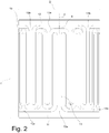
figure 2 is a side view of the joint infigure 1 ; -
figure 3 is an axonometric view of a joint according to a second embodiment of the invention; -
figure 4 is a schematic depiction useful to show, more generally, the structural principle of the joint according to the invention; and -
figures 5a to 5d are diagrams that follow the depiction scheme offigure 4 and consistently with the latter show respective joint modules according to various embodiments of the invention; the drawings infigure 5a and figure 5b correspond in particular respectively to the first embodiment (as per the previousfigures 1 and2 ) and to the second embodiment (as perfigure 3 ); -
figures 6a to 6c are schematizations of the joint according to the invention, and more specifically according to the second embodiment infigure 3 , that outline the joint in terms of a system of cantilever beams and relative equivalent springs. - With reference for the time being to
figures 1 and2 , a joint according to the present invention is obtained starting from a unitary body 1, typically a metal body, having a tubular structure, where tubular means generically a hollow structure, evolving around aninner cavity 1a, with an axial symmetry. In particular, as in the first embodiment shown in the cited figures, the body can be, according to a preferred solution, a cylinder having a central axis X and a circular basis; however, more generally speaking, the basic outline of the body (that is, the outer perimeter of the section on a transversal plane orthogonal to the central axis) may be polygonal, thus resulting in a prismatic shape of the body. Even more generally, such basic outline may also vary in size along the central axis, that is, remaining identical to itself aside from a scale factor (which will preferably be comprised between 1 and 3, both ends included); in this case the body can take on, for example, a hourglass shape or a barrel shape. The body 1 has an elongation L measured along the axis X. The diameter of the basic outline, here the outer diameter of the circular section of the body, is indicated with D. The ratio between L and D may vary substantially at will, even though for most applications, a ratio of L/D ≥ 1 may be advantageous. - According to the invention, the body 1 has a distribution of
slots 1b formed through removal or excavation of material, this resulting in a windowed structure of the body, wherein theinner cavity 1a is opened outwards through the slots, and the remaining solid material defines a pattern (that is a path or mesh) of beam-shapedmembers 13 which join twoannular elements - The
annular elements - Specifically regarding the beam-shaped
pattern 13, it has a plurality ofjunctions annular elements annular element 11 and a junction to a secondannular element 12, where obviously "first" and "second" are entirely interchangeable references. - Two consecutive junctions on the same annular element, or more precisely their midpoints, define a module M of the pattern which repeats serially in identical form for a certain number of times (at least two) when following the aforesaid circle, wherein two consecutive modules clearly share at least one junction. For example, among the above-mentioned two junctions to the first annular element 11 (indicated with 13a' and 13a" in
figure 1 ), the module M includes onejunction 13b' to the opposite annular element (or second annular element 12), which midpoint identifies, with the central axis X, a plane α of inner mirror-image symmetry of the module M. - In practice, the evolution or geometric path of the beams forming the pattern between one of the
end junctions 13a' of the module M to the firstannular element 11 and the "central"junction 13b' of the module to the secondannular element 12 mirrors the evolution or path which joins suchcentral junction 13b' to theother end junction 13a", with respect to the plane α passing through the axis X and the midpoint of the central junction. Generally speaking, said path substantially follows a curved line, typically but not necessarily having a variable curvature, a polyline with at least three straight line segments, or a combination of straight line segments and curved lines even having variable curvature. - In particular, in the module according to the presently described embodiment, a main beam-shaped
member 13c', 13c" and 13d' (the first two respectively from the two end junctions and the third from the central junction) branches off from each junction, extending axially, that is along a generatrix parallel to the axis X, with the first end of each member integral with the relative annular element and which identifies the junction, and the second end which reaches close to the opposite annular element by a distance S measured axially which advantageously may be equal to or less than about 1/5 of the elongation L. - Such second ends, or more precisely each second end and the second end of the consecutive main beam-shaped member (projecting from different annular elements: here therefore, for example, the second end of the main beam-shaped
member 13d' and the second end of the main beam-shapedmember 13c'), are then joined byconnection members 13e which according to the present embodiment, preferably have a serpentine shape, comprising at least one axial beam-shapedsegment 13e' (three here) extending parallel to the axis X for a length for example, equal to about L-2·S. Therefore, in this embodiment, the slots define a plurality of beam-shaped members/segments that are regularly spaced following the circumferential direction, the spacing being variable depending on the circumstances of use, absolute size and proportions of the body etc. The serpentine shape is then completed bycircumferential bridging segments 13e", with corners that, though rounded, are in any case substantially at right angles, and that can degenerate into sharp portions when the distance between two axial segments is close like in the example. - With reference to
figure 3 , a second embodiment of the invention is practically a close variant of the first one just described, as can also be understood by the use of consistent and self-explanatory reference numerals. Here, the annular elements and the beam-shaped members are thicker both in the radial direction (due to the effect of a tubular body with an inner cavity having a reduced size in relation to the outer diameter D) and in the axial direction (as far as the annular elements and the circumferential beam-shaped segments are concerned) and circumferential direction (as far as the axial beam-shaped members/segments). In terms of the evolution of the pattern, it is worth noting here the provision of a serpentine shape with a single axial segment between two consecutive main beam-shaped members. - With reference then also to
figures 4 to 5d , geometric schematizations are provided of various possible beam patterns in a joint according to the invention. More specifically,figures 5a and 5b show respective schematizations of a module M of the first and the second embodiment. In these representations, the inner pattern of the module is expressed in the more generic terms of the relevant paths, as already mentioned above, that are mutually symmetrical with respect to the plane α and here indicated with T1, T2, each evolving between one junction to an annular element and the consecutive junction to the other annular element. In the two examples taken into consideration, the path of the pattern is practically a polyline having several straight segments, an expedient that, clearly, can be pursued also by other examples alike the ones infigures 5c and 5d , having main axial beam-shaped members with a shorter axial elongation, which are joined by simple connection segments, here for example with a certain slanting (not right) angle. - But even more generally, as shown in
figure 4 , the paths T1 and T2 may follow curved lines or combinations of straight line segments with parts of a curved line, for example and typically according to a spline function. In this figure, in which the development of the circle c circumscribed to the basic outline of the body is also marked (a basic outline that, as mentioned, may not be circular), it is also worth noting a possible preferred solution, according to which the tangent t to the path at the junction to the respective annular element is a generatrix of the cylinder having its base in the circle c, and the module M extends between two generatrices/tangents t in two consecutive junctions on the same annular element. - The joint according to the invention, as in particular implemented based on the examples described above, but in general according to the features defined by the main appended claim, completely achieves the objects set out in the introductory part. The elastic joint here proposed is remarkably simple from a manufacturing standpoint, in particular by making use of laser cutting technology for metal materials; besides, the design considerations are assisted by the fact that the equivalent stiffness can be easily determined.
- This results in affordable costs and a straightforward customization of the properties.
- Since the body 1 is a single metal piece, when remaining in the range of elastic deformation, the advantage is attained of not dealing with hysteresis in the loading and unloading cycles. Moreover, precisely for making use of a single piece rigid body, the joint is a CV joint (aside from the deformation, which however is linear and known).
- Due to its geometry, the joint allows for an intrinsic adjustment between the input and output axes when the coaxiality tolerance is not perfectly complied with. For it being inherently elastic, the joint is also compliant with an axial elasticity component which is useful when there is hyperstaticity between actuating and actuated device.
- Finally, the elastic joint leaves an inner free space (indeed a remarkable one if compared to the overall bulk of the joint) for the arrangement of accessory components (wiring etc.) coaxially to the input and output devices.
- Considering more thoroughly the issue of identifying the equivalent torsional rigidity, this can be easily calculated because, to a very good approximation, the beam-shaped components of the examples indicated above can be considered for example as an appropriate combination of cantilever beams, according to the schemes in
figures 6a to 6c which can be interpreted in light of the following formulas:


- Mt = Twisting couple [N mm]
- R = Average radius of the cylinder [mm]
- L1...n = Free length of the beams [mm]
- I1...n = Flexural moments of inertia [mm4]
- E = Young's modulus [Mpa]
- δ1...n= Cantilever beam inflexion [mm]
- K1...n = Elastic constant of the spring [N·mm/rad]
- Keqv = Overall equivalent elastic constant of the elastic joint [N·mm/rad]
- The desired stiffness can be optimized by acting on the various geometric parameters, such as in particular, as mentioned, the thickness and the sizes of the beam-shaped segments or members. Obviously, a fundamental variable for obtaining the features desired is the material used: the most suitable materials are the metal materials used generally for mechanical constructions. Among them, steel, aluminium alloys and titanium alloys. Primarily, the fundamental value for choosing and obtaining the desired stiffness properties of the joint can be identified in the Young's modulus of the material. The selection of the material to be used, as well as the desired stiffness, is in a direct connection with the extent of the load that the joint has to bear and the level of dimensional compactness that one wishes to obtain.
- Then, to summarize, the slots can be made with laser cutting systems on a basic tubular body made of metal, such as a generally resistant and flexible steel e, e.g. spring steel (for example, Böhler W720 maraging steel with a Young's modulus of 193 GPa and a yield stress of 1815 MPa). As far as compatible with the size of the slots and with the size of the cross-section of the whole element, manufacturing by traditional metal working machines (stock removal machining) may also be possible.
- Other advantages which may result from using the joint according to the invention comprise:
- the joint is usable for transmissions requiring an elastic joint between input and output with a known stiffness or torsion constant, without hysteresis and as a low-pass filter;
- it can be coupled with a position transducer (e.g. a rotary encoder) as sensitive element for highly accurate torque sensors, which can be customized, provided with an axial bore and at a low cost;
- usability simply as a hollow torsional spring.
- The joint may have several applications, among which one of particular interest being robotics, and in particular wearable robotics. The sizes thereof and its features of rigidity and transmittable torque and its increased capability to be interfaced with the other elements make it a useful element for making elastic actuators for wearable robots and for robots generally. In these applications, it is indeed fundamental to use actuators provided with intrinsic compliance, with limited weights and volumes, albeit with the need to transmit relatively high torques and forces. The joint according to the invention, complete with all elements, may be assembled directly on the robot.
- The present invention was described hereto with reference to preferred embodiments thereof. It is intended that other embodiments may exist which relate to the same inventive concept within the scope of protection of the claims here attached.
Claims (12)
- A transmissive joint with elastic response for transmitting a torsional load between an actuating and an actuated device, the joint comprising a unitary body having a tubular structure around a central or longitudinal axis (X), the body showing a basic outline defined by sections on any planes orthogonal with said axis (X) that are mutually identical aside from a scale factor; a distribution of slots being formed in said body through removal of material, said slots defining the following elements in the same body:- at respective longitudinal ends of said body, a first and second annular element (11, 12), lying over planes orthogonal with said central axis (X) and spaced along it, said annular elements being adapted for a mechanical connection with the actuating or the actuated device; and- a beam-shaped pattern extending between said annular elements and providing for a plurality of junctions (13a, 13b) to respective of said elements;
▪ wherein said junctions (13a, 13b) are in the same number for each annular element and regularly spaced following a direction defined by a circle (c) circumscribed to said outline, in a sequence that comprises alternatively a junction to the first annular element and a junction to the second annular element; characterised in that said pattern comprises at least two modules (M) each comprised between the midpoint of respective consecutive junctions on the same annular element, said modules repeating serially along said circumference, at least one junction being shared among two adjacent modules, the modules having each an internal symmetry mirrored with respect to plane (α) passing through said central axis (X) and for the midpoint of the single junction of the module to the opposed annular element; and wherein between a junction to an annular element and the consecutive junction to the other annular element said pattern follows a path substantially in accordance with a curved line, a polyline with at least three straight line segments, or a combination of straight line segments and curved lines. - The transmissive joint according to claim 1, wherein said body has an elongation (L) along said central axis (X) equal to or greater than the diameter of said circle circumscribing the outline.
- The transmissive joint according to claim 2, wherein each of said modules comprise three main beam-shaped members (13c', 13c", 13d') extending in an essentially axial direction starting from respective first ends that define respective spaced junctions alternatively to said first and second annular element and having each a second end axially spaced from the annular element opposed to the element to which the first end is integral, the module further comprising one or more connection members (13e) joining the second end of each main beam-shaped member to the second end of at least one beam-shaped member that is circumferentially consecutive in the same module.
- The transmissive joint according to claim 3, wherein the second end of each main beam-shaped member is axially spaced from the annular element opposed to the element to which the first end is integral by a gap distance (S) not greater than 1/5 of said elongation (L).
- The transmissive joint according to claim 4, wherein said connection members develop according to a serpentine shape, comprising at least one axial beam-shaped segment (13e') extending parallel with said central axis (X).
- The transmissive joint according to claim 5, wherein said at least one axial beam-shaped segment (13e') extends axially for a length equal to said elongation (L) minus twice said gap distance (S).
- The transmissive joint according to claim 5 or 6, wherein said connection members further comprise a plurality of circumferential bridging segments (13e") that extend between two axial beam-shaped segments (13e') and/or between an axial beam-shaped segment (13e') and a main beam-shaped member (13c', 13c", 13d').
- The transmissive joint according to claim 3, wherein said connection members comprise single connection segments each extending between two main beam-shaped members that are consecutive following a circumferential direction and project from two different annular members.
- The transmissive joint according to any of the previous claims, wherein the tangent (t) to said path at the junction to the respective annular member is a generatrix of a cylinder having a base outlined by said circle (c), said module (M) being comprised between two generatrices/tangents (t) at two consecutive junctions to the same annular member.
- The transmissive joint according to any of the previous claims, wherein said scale factor is higher than or equal to 1 and lower than or equal to 3.
- The transmissive joint according to any of the previous claims, wherein said body is cylindrical with a circular basis.
- The transmissive joint according to any of the claims from 1 to 10, wherein said body is prismatic.
Applications Claiming Priority (2)
| Application Number | Priority Date | Filing Date | Title |
|---|---|---|---|
| ITUA2016A004465A ITUA20164465A1 (en) | 2016-06-17 | 2016-06-17 | JOINT FOR THE TRANSMISSION OF A TORSIONAL STRESS WITH ELASTIC RESPONSE |
| PCT/IB2017/053531 WO2017216740A1 (en) | 2016-06-17 | 2017-06-14 | Joint for transmitting a torsional load with elastic response |
Publications (2)
| Publication Number | Publication Date |
|---|---|
| EP3472483A1 EP3472483A1 (en) | 2019-04-24 |
| EP3472483B1 true EP3472483B1 (en) | 2020-02-12 |
Family
ID=57209717
Family Applications (1)
| Application Number | Title | Priority Date | Filing Date |
|---|---|---|---|
| EP17733903.3A Active EP3472483B1 (en) | 2016-06-17 | 2017-06-14 | Joint for transmitting a torsional load with elastic response |
Country Status (9)
| Country | Link |
|---|---|
| US (2) | US11408478B2 (en) |
| EP (1) | EP3472483B1 (en) |
| CN (1) | CN109312787B (en) |
| BR (1) | BR112018073331A2 (en) |
| CA (1) | CA3019479A1 (en) |
| IT (1) | ITUA20164465A1 (en) |
| MX (1) | MX2018014268A (en) |
| RU (1) | RU2721040C1 (en) |
| WO (1) | WO2017216740A1 (en) |
Families Citing this family (4)
| Publication number | Priority date | Publication date | Assignee | Title |
|---|---|---|---|---|
| CN114438870B (en) * | 2022-03-07 | 2024-06-07 | 重庆交通大学 | Upper bearing type steel pipe concrete arch bridge with damping device on main arch ring |
| KR20250073446A (en) * | 2022-11-07 | 2025-05-27 | 미츠비시 파워 가부시키가이샤 | Support device and method for manufacturing the support device |
| US12607232B2 (en) | 2023-03-27 | 2026-04-21 | Goodrich Corporation | Flexible metallic coupling for drive shafts made by additive manufacturing |
| DE202023102375U1 (en) * | 2023-05-02 | 2023-05-15 | Kwd Kupplungswerk Dresden Gmbh | Spatially flexible coupling and coupling assembly |
Family Cites Families (21)
| Publication number | Priority date | Publication date | Assignee | Title |
|---|---|---|---|---|
| US1557958A (en) * | 1924-08-26 | 1925-10-20 | American Mach & Foundry | Flexible coupling |
| GB1104284A (en) * | 1964-08-07 | 1968-02-21 | Wellman Bibby Company Ltd | Improvements in or relating to flexible couplings |
| US4790700A (en) * | 1984-07-30 | 1988-12-13 | Schwartzman Everett H | Integral spring flexure for use with high speed rotating shafts |
| US4690661A (en) * | 1985-08-26 | 1987-09-01 | Rexnord Inc. | Torsional stress distribution flexible coupling |
| DE3822417A1 (en) * | 1987-07-15 | 1989-01-26 | Man Technologie Gmbh | Shaft for transmitting torsional forces |
| US5160121A (en) * | 1991-03-25 | 1992-11-03 | Proprietary Technology, Inc. | Shock absorbing compressional mounting apparatus |
| US5238454A (en) * | 1991-06-10 | 1993-08-24 | Build-A-Mold Limited | One-piece flexible coupling having a plurality of axially spaced disks |
| DE19509116C2 (en) * | 1995-03-16 | 2000-01-05 | Deutsch Zentr Luft & Raumfahrt | Flexible structure |
| DE19811098C2 (en) * | 1998-03-13 | 2003-07-03 | Wifag Maschf | Storage of a rotating body of a printing press |
| US6241224B1 (en) | 1999-09-30 | 2001-06-05 | Xerox Corporation | Torsion spring |
| DE10213382A1 (en) * | 2002-03-26 | 2003-10-16 | Bosch Gmbh Robert | Fuel injection valve |
| KR100541769B1 (en) * | 2004-06-25 | 2006-01-10 | 모나스펌프 주식회사 | Flexible transmission shaft |
| DE102005014985A1 (en) | 2005-04-01 | 2006-10-05 | Bhs Getriebe Gmbh | Membrane coupling unit for torque transmission unit, has rotation elastic arrangement to distribute rotation elasticity to coupling unit and fastened at circumferential regions and extending in circumferential direction along distribution |
| US20060276247A1 (en) * | 2005-06-03 | 2006-12-07 | Martinez Jaime E | Flexible shaft |
| US8480054B2 (en) * | 2008-05-30 | 2013-07-09 | Woodward, Inc. | Tortionally stiff, thermally isolating shaft coupling with multiple degrees of freedom to accommodate misalignment |
| FR2996890B1 (en) * | 2012-10-12 | 2014-12-12 | Sagem Defense Securite | SUPPORT ASSEMBLY OF AN ORIENTABLE ELEMENT, AND OPTICAL EQUIPMENT INCORPORATING SUCH AN ASSEMBLY |
| ITFI20130156A1 (en) * | 2013-07-01 | 2015-01-02 | Scuola Superiore Sant Anna | TORSIONAL SPRING |
| US20150145191A1 (en) * | 2013-11-26 | 2015-05-28 | Honeywell International Inc. | Isolators having nested flexure devices and methods for the production thereof |
| DE102014109754B4 (en) * | 2014-07-11 | 2016-03-31 | Pierburg Gmbh | Coupling device for connecting two opposing shafts and method for producing such a coupling device |
| US20170328416A1 (en) * | 2016-05-11 | 2017-11-16 | Ulterra Drilling Technologies, L.P. | Universal Joint |
| EP3477139B1 (en) * | 2017-10-30 | 2020-12-09 | Crompton Technology Group Limited | Composite flexible coupling |
-
2016
- 2016-06-17 IT ITUA2016A004465A patent/ITUA20164465A1/en unknown
-
2017
- 2017-06-14 US US16/309,285 patent/US11408478B2/en active Active
- 2017-06-14 EP EP17733903.3A patent/EP3472483B1/en active Active
- 2017-06-14 CA CA3019479A patent/CA3019479A1/en not_active Abandoned
- 2017-06-14 MX MX2018014268A patent/MX2018014268A/en unknown
- 2017-06-14 WO PCT/IB2017/053531 patent/WO2017216740A1/en not_active Ceased
- 2017-06-14 RU RU2018141670A patent/RU2721040C1/en active
- 2017-06-14 BR BR112018073331-8A patent/BR112018073331A2/en not_active Application Discontinuation
- 2017-06-14 CN CN201780035971.1A patent/CN109312787B/en active Active
-
2022
- 2022-07-12 US US17/862,538 patent/US11725707B2/en active Active
Non-Patent Citations (1)
| Title |
|---|
| None * |
Also Published As
| Publication number | Publication date |
|---|---|
| RU2721040C1 (en) | 2020-05-15 |
| US20190331186A1 (en) | 2019-10-31 |
| US20220381300A1 (en) | 2022-12-01 |
| BR112018073331A2 (en) | 2019-02-26 |
| US11725707B2 (en) | 2023-08-15 |
| EP3472483A1 (en) | 2019-04-24 |
| CN109312787A (en) | 2019-02-05 |
| MX2018014268A (en) | 2019-07-04 |
| CN109312787B (en) | 2021-06-29 |
| ITUA20164465A1 (en) | 2017-12-17 |
| WO2017216740A1 (en) | 2017-12-21 |
| US11408478B2 (en) | 2022-08-09 |
| CA3019479A1 (en) | 2017-12-21 |
Similar Documents
| Publication | Publication Date | Title |
|---|---|---|
| US11725707B2 (en) | Joint for transmitting a torsional load with elastic response | |
| US5135060A (en) | Articulated coupling for use with a downhole drilling apparatus | |
| US9676104B2 (en) | Variable spring constant torque coupler | |
| JP2010532718A (en) | Torque sensing unit for power tool and power tool including the torque sensing unit | |
| US20180209484A1 (en) | Torsional transmission element with elastic response | |
| EP3884180B1 (en) | A planar torsional spring | |
| Benhabib et al. | Mechanical design of a modular robot for industrial applications | |
| US4003218A (en) | Constant velocity universal joint | |
| US10364858B2 (en) | Planar flexure members and actuators using them | |
| SE448286B (en) | BUILDING ROBOT ARM | |
| EP3396190B1 (en) | Rigid connecting rod coupling between two shafts | |
| EP3861225B1 (en) | Device for the selective transmission of driving torques | |
| GB2086009A (en) | Flexible transmission | |
| JPH06221339A (en) | Shaft coupling for rotary transmission shaft | |
| JP6587323B2 (en) | Torque detection mechanism | |
| SU766855A1 (en) | Working member of industrial robot | |
| EP0412334A1 (en) | Mechanical coupling assembly | |
| RU2017031C1 (en) | Planet gear | |
| RU2222734C2 (en) | Reduction gear | |
| KR100299794B1 (en) | structure of universal joint for vehicle | |
| JP2022091418A (en) | Flexible fittings and goniometers | |
| JPH02159417A (en) | Flexible shaft coupling | |
| KR20080034561A (en) | Ball universal joint | |
| GB1559347A (en) | Universal joint |
Legal Events
| Date | Code | Title | Description |
|---|---|---|---|
| STAA | Information on the status of an ep patent application or granted ep patent |
Free format text: STATUS: UNKNOWN |
|
| STAA | Information on the status of an ep patent application or granted ep patent |
Free format text: STATUS: THE INTERNATIONAL PUBLICATION HAS BEEN MADE |
|
| PUAI | Public reference made under article 153(3) epc to a published international application that has entered the european phase |
Free format text: ORIGINAL CODE: 0009012 |
|
| STAA | Information on the status of an ep patent application or granted ep patent |
Free format text: STATUS: REQUEST FOR EXAMINATION WAS MADE |
|
| 17P | Request for examination filed |
Effective date: 20181105 |
|
| AK | Designated contracting states |
Kind code of ref document: A1 Designated state(s): AL AT BE BG CH CY CZ DE DK EE ES FI FR GB GR HR HU IE IS IT LI LT LU LV MC MK MT NL NO PL PT RO RS SE SI SK SM TR |
|
| AX | Request for extension of the european patent |
Extension state: BA ME |
|
| DAV | Request for validation of the european patent (deleted) | ||
| DAX | Request for extension of the european patent (deleted) | ||
| GRAP | Despatch of communication of intention to grant a patent |
Free format text: ORIGINAL CODE: EPIDOSNIGR1 |
|
| STAA | Information on the status of an ep patent application or granted ep patent |
Free format text: STATUS: GRANT OF PATENT IS INTENDED |
|
| INTG | Intention to grant announced |
Effective date: 20191030 |
|
| RAP1 | Party data changed (applicant data changed or rights of an application transferred) |
Owner name: SCUOLA SUPERIORE DI STUDI UNIVERSITARI E DI PERFEZ |
|
| GRAS | Grant fee paid |
Free format text: ORIGINAL CODE: EPIDOSNIGR3 |
|
| GRAA | (expected) grant |
Free format text: ORIGINAL CODE: 0009210 |
|
| STAA | Information on the status of an ep patent application or granted ep patent |
Free format text: STATUS: THE PATENT HAS BEEN GRANTED |
|
| AK | Designated contracting states |
Kind code of ref document: B1 Designated state(s): AL AT BE BG CH CY CZ DE DK EE ES FI FR GB GR HR HU IE IS IT LI LT LU LV MC MK MT NL NO PL PT RO RS SE SI SK SM TR |
|
| REG | Reference to a national code |
Ref country code: GB Ref legal event code: FG4D |
|
| REG | Reference to a national code |
Ref country code: CH Ref legal event code: EP |
|
| REG | Reference to a national code |
Ref country code: AT Ref legal event code: REF Ref document number: 1232500 Country of ref document: AT Kind code of ref document: T Effective date: 20200215 |
|
| REG | Reference to a national code |
Ref country code: IE Ref legal event code: FG4D |
|
| REG | Reference to a national code |
Ref country code: DE Ref legal event code: R096 Ref document number: 602017011729 Country of ref document: DE |
|
| PG25 | Lapsed in a contracting state [announced via postgrant information from national office to epo] |
Ref country code: RS Free format text: LAPSE BECAUSE OF FAILURE TO SUBMIT A TRANSLATION OF THE DESCRIPTION OR TO PAY THE FEE WITHIN THE PRESCRIBED TIME-LIMIT Effective date: 20200212 Ref country code: FI Free format text: LAPSE BECAUSE OF FAILURE TO SUBMIT A TRANSLATION OF THE DESCRIPTION OR TO PAY THE FEE WITHIN THE PRESCRIBED TIME-LIMIT Effective date: 20200212 Ref country code: NO Free format text: LAPSE BECAUSE OF FAILURE TO SUBMIT A TRANSLATION OF THE DESCRIPTION OR TO PAY THE FEE WITHIN THE PRESCRIBED TIME-LIMIT Effective date: 20200512 |
|
| REG | Reference to a national code |
Ref country code: LT Ref legal event code: MG4D |
|
| REG | Reference to a national code |
Ref country code: NL Ref legal event code: MP Effective date: 20200212 |
|
| PG25 | Lapsed in a contracting state [announced via postgrant information from national office to epo] |
Ref country code: SE Free format text: LAPSE BECAUSE OF FAILURE TO SUBMIT A TRANSLATION OF THE DESCRIPTION OR TO PAY THE FEE WITHIN THE PRESCRIBED TIME-LIMIT Effective date: 20200212 Ref country code: LV Free format text: LAPSE BECAUSE OF FAILURE TO SUBMIT A TRANSLATION OF THE DESCRIPTION OR TO PAY THE FEE WITHIN THE PRESCRIBED TIME-LIMIT Effective date: 20200212 Ref country code: BG Free format text: LAPSE BECAUSE OF FAILURE TO SUBMIT A TRANSLATION OF THE DESCRIPTION OR TO PAY THE FEE WITHIN THE PRESCRIBED TIME-LIMIT Effective date: 20200512 Ref country code: IS Free format text: LAPSE BECAUSE OF FAILURE TO SUBMIT A TRANSLATION OF THE DESCRIPTION OR TO PAY THE FEE WITHIN THE PRESCRIBED TIME-LIMIT Effective date: 20200612 Ref country code: GR Free format text: LAPSE BECAUSE OF FAILURE TO SUBMIT A TRANSLATION OF THE DESCRIPTION OR TO PAY THE FEE WITHIN THE PRESCRIBED TIME-LIMIT Effective date: 20200513 Ref country code: HR Free format text: LAPSE BECAUSE OF FAILURE TO SUBMIT A TRANSLATION OF THE DESCRIPTION OR TO PAY THE FEE WITHIN THE PRESCRIBED TIME-LIMIT Effective date: 20200212 |
|
| PG25 | Lapsed in a contracting state [announced via postgrant information from national office to epo] |
Ref country code: NL Free format text: LAPSE BECAUSE OF FAILURE TO SUBMIT A TRANSLATION OF THE DESCRIPTION OR TO PAY THE FEE WITHIN THE PRESCRIBED TIME-LIMIT Effective date: 20200212 |
|
| PG25 | Lapsed in a contracting state [announced via postgrant information from national office to epo] |
Ref country code: SK Free format text: LAPSE BECAUSE OF FAILURE TO SUBMIT A TRANSLATION OF THE DESCRIPTION OR TO PAY THE FEE WITHIN THE PRESCRIBED TIME-LIMIT Effective date: 20200212 Ref country code: SM Free format text: LAPSE BECAUSE OF FAILURE TO SUBMIT A TRANSLATION OF THE DESCRIPTION OR TO PAY THE FEE WITHIN THE PRESCRIBED TIME-LIMIT Effective date: 20200212 Ref country code: EE Free format text: LAPSE BECAUSE OF FAILURE TO SUBMIT A TRANSLATION OF THE DESCRIPTION OR TO PAY THE FEE WITHIN THE PRESCRIBED TIME-LIMIT Effective date: 20200212 Ref country code: DK Free format text: LAPSE BECAUSE OF FAILURE TO SUBMIT A TRANSLATION OF THE DESCRIPTION OR TO PAY THE FEE WITHIN THE PRESCRIBED TIME-LIMIT Effective date: 20200212 Ref country code: ES Free format text: LAPSE BECAUSE OF FAILURE TO SUBMIT A TRANSLATION OF THE DESCRIPTION OR TO PAY THE FEE WITHIN THE PRESCRIBED TIME-LIMIT Effective date: 20200212 Ref country code: CZ Free format text: LAPSE BECAUSE OF FAILURE TO SUBMIT A TRANSLATION OF THE DESCRIPTION OR TO PAY THE FEE WITHIN THE PRESCRIBED TIME-LIMIT Effective date: 20200212 Ref country code: RO Free format text: LAPSE BECAUSE OF FAILURE TO SUBMIT A TRANSLATION OF THE DESCRIPTION OR TO PAY THE FEE WITHIN THE PRESCRIBED TIME-LIMIT Effective date: 20200212 Ref country code: PT Free format text: LAPSE BECAUSE OF FAILURE TO SUBMIT A TRANSLATION OF THE DESCRIPTION OR TO PAY THE FEE WITHIN THE PRESCRIBED TIME-LIMIT Effective date: 20200705 Ref country code: LT Free format text: LAPSE BECAUSE OF FAILURE TO SUBMIT A TRANSLATION OF THE DESCRIPTION OR TO PAY THE FEE WITHIN THE PRESCRIBED TIME-LIMIT Effective date: 20200212 |
|
| REG | Reference to a national code |
Ref country code: DE Ref legal event code: R097 Ref document number: 602017011729 Country of ref document: DE |
|
| REG | Reference to a national code |
Ref country code: AT Ref legal event code: MK05 Ref document number: 1232500 Country of ref document: AT Kind code of ref document: T Effective date: 20200212 |
|
| PLBE | No opposition filed within time limit |
Free format text: ORIGINAL CODE: 0009261 |
|
| STAA | Information on the status of an ep patent application or granted ep patent |
Free format text: STATUS: NO OPPOSITION FILED WITHIN TIME LIMIT |
|
| 26N | No opposition filed |
Effective date: 20201113 |
|
| PG25 | Lapsed in a contracting state [announced via postgrant information from national office to epo] |
Ref country code: MC Free format text: LAPSE BECAUSE OF FAILURE TO SUBMIT A TRANSLATION OF THE DESCRIPTION OR TO PAY THE FEE WITHIN THE PRESCRIBED TIME-LIMIT Effective date: 20200212 Ref country code: AT Free format text: LAPSE BECAUSE OF FAILURE TO SUBMIT A TRANSLATION OF THE DESCRIPTION OR TO PAY THE FEE WITHIN THE PRESCRIBED TIME-LIMIT Effective date: 20200212 Ref country code: IT Free format text: LAPSE BECAUSE OF FAILURE TO SUBMIT A TRANSLATION OF THE DESCRIPTION OR TO PAY THE FEE WITHIN THE PRESCRIBED TIME-LIMIT Effective date: 20200212 |
|
| REG | Reference to a national code |
Ref country code: CH Ref legal event code: PL |
|
| PG25 | Lapsed in a contracting state [announced via postgrant information from national office to epo] |
Ref country code: SI Free format text: LAPSE BECAUSE OF FAILURE TO SUBMIT A TRANSLATION OF THE DESCRIPTION OR TO PAY THE FEE WITHIN THE PRESCRIBED TIME-LIMIT Effective date: 20200212 Ref country code: PL Free format text: LAPSE BECAUSE OF FAILURE TO SUBMIT A TRANSLATION OF THE DESCRIPTION OR TO PAY THE FEE WITHIN THE PRESCRIBED TIME-LIMIT Effective date: 20200212 |
|
| PG25 | Lapsed in a contracting state [announced via postgrant information from national office to epo] |
Ref country code: LU Free format text: LAPSE BECAUSE OF NON-PAYMENT OF DUE FEES Effective date: 20200614 |
|
| REG | Reference to a national code |
Ref country code: BE Ref legal event code: MM Effective date: 20200630 |
|
| PG25 | Lapsed in a contracting state [announced via postgrant information from national office to epo] |
Ref country code: IE Free format text: LAPSE BECAUSE OF NON-PAYMENT OF DUE FEES Effective date: 20200614 Ref country code: CH Free format text: LAPSE BECAUSE OF NON-PAYMENT OF DUE FEES Effective date: 20200630 Ref country code: LI Free format text: LAPSE BECAUSE OF NON-PAYMENT OF DUE FEES Effective date: 20200630 |
|
| PG25 | Lapsed in a contracting state [announced via postgrant information from national office to epo] |
Ref country code: BE Free format text: LAPSE BECAUSE OF NON-PAYMENT OF DUE FEES Effective date: 20200630 |
|
| PG25 | Lapsed in a contracting state [announced via postgrant information from national office to epo] |
Ref country code: TR Free format text: LAPSE BECAUSE OF FAILURE TO SUBMIT A TRANSLATION OF THE DESCRIPTION OR TO PAY THE FEE WITHIN THE PRESCRIBED TIME-LIMIT Effective date: 20200212 Ref country code: MT Free format text: LAPSE BECAUSE OF FAILURE TO SUBMIT A TRANSLATION OF THE DESCRIPTION OR TO PAY THE FEE WITHIN THE PRESCRIBED TIME-LIMIT Effective date: 20200212 Ref country code: CY Free format text: LAPSE BECAUSE OF FAILURE TO SUBMIT A TRANSLATION OF THE DESCRIPTION OR TO PAY THE FEE WITHIN THE PRESCRIBED TIME-LIMIT Effective date: 20200212 |
|
| PG25 | Lapsed in a contracting state [announced via postgrant information from national office to epo] |
Ref country code: MK Free format text: LAPSE BECAUSE OF FAILURE TO SUBMIT A TRANSLATION OF THE DESCRIPTION OR TO PAY THE FEE WITHIN THE PRESCRIBED TIME-LIMIT Effective date: 20200212 Ref country code: AL Free format text: LAPSE BECAUSE OF FAILURE TO SUBMIT A TRANSLATION OF THE DESCRIPTION OR TO PAY THE FEE WITHIN THE PRESCRIBED TIME-LIMIT Effective date: 20200212 |
|
| PGFP | Annual fee paid to national office [announced via postgrant information from national office to epo] |
Ref country code: DE Payment date: 20250618 Year of fee payment: 9 |
|
| PGFP | Annual fee paid to national office [announced via postgrant information from national office to epo] |
Ref country code: GB Payment date: 20250618 Year of fee payment: 9 |
|
| PGFP | Annual fee paid to national office [announced via postgrant information from national office to epo] |
Ref country code: FR Payment date: 20250617 Year of fee payment: 9 |