EP3472264B1 - Retractable center feed injection device - Google Patents
Retractable center feed injection device Download PDFInfo
- Publication number
- EP3472264B1 EP3472264B1 EP16905670.2A EP16905670A EP3472264B1 EP 3472264 B1 EP3472264 B1 EP 3472264B1 EP 16905670 A EP16905670 A EP 16905670A EP 3472264 B1 EP3472264 B1 EP 3472264B1
- Authority
- EP
- European Patent Office
- Prior art keywords
- injection nozzle
- coke drum
- opening
- feed inlet
- feed
- Prior art date
- Legal status (The legal status is an assumption and is not a legal conclusion. Google has not performed a legal analysis and makes no representation as to the accuracy of the status listed.)
- Active
Links
Images





Classifications
-
- C—CHEMISTRY; METALLURGY
- C10—PETROLEUM, GAS OR COKE INDUSTRIES; TECHNICAL GASES CONTAINING CARBON MONOXIDE; FUELS; LUBRICANTS; PEAT
- C10B—DESTRUCTIVE DISTILLATION OF CARBONACEOUS MATERIALS FOR PRODUCTION OF GAS, COKE, TAR, OR SIMILAR MATERIALS
- C10B31/00—Charging devices
- C10B31/12—Charging devices for liquid materials
-
- B—PERFORMING OPERATIONS; TRANSPORTING
- B01—PHYSICAL OR CHEMICAL PROCESSES OR APPARATUS IN GENERAL
- B01J—CHEMICAL OR PHYSICAL PROCESSES, e.g. CATALYSIS OR COLLOID CHEMISTRY; THEIR RELEVANT APPARATUS
- B01J4/00—Feed or outlet devices; Feed or outlet control devices
- B01J4/001—Feed or outlet devices as such, e.g. feeding tubes
- B01J4/002—Nozzle-type elements
-
- B—PERFORMING OPERATIONS; TRANSPORTING
- B01—PHYSICAL OR CHEMICAL PROCESSES OR APPARATUS IN GENERAL
- B01J—CHEMICAL OR PHYSICAL PROCESSES, e.g. CATALYSIS OR COLLOID CHEMISTRY; THEIR RELEVANT APPARATUS
- B01J4/00—Feed or outlet devices; Feed or outlet control devices
- B01J4/001—Feed or outlet devices as such, e.g. feeding tubes
- B01J4/007—Feed or outlet devices as such, e.g. feeding tubes provided with moving parts
-
- C—CHEMISTRY; METALLURGY
- C10—PETROLEUM, GAS OR COKE INDUSTRIES; TECHNICAL GASES CONTAINING CARBON MONOXIDE; FUELS; LUBRICANTS; PEAT
- C10B—DESTRUCTIVE DISTILLATION OF CARBONACEOUS MATERIALS FOR PRODUCTION OF GAS, COKE, TAR, OR SIMILAR MATERIALS
- C10B1/00—Retorts
- C10B1/02—Stationary retorts
- C10B1/04—Vertical retorts
-
- C—CHEMISTRY; METALLURGY
- C10—PETROLEUM, GAS OR COKE INDUSTRIES; TECHNICAL GASES CONTAINING CARBON MONOXIDE; FUELS; LUBRICANTS; PEAT
- C10B—DESTRUCTIVE DISTILLATION OF CARBONACEOUS MATERIALS FOR PRODUCTION OF GAS, COKE, TAR, OR SIMILAR MATERIALS
- C10B31/00—Charging devices
- C10B31/06—Charging devices for charging horizontally
-
- C—CHEMISTRY; METALLURGY
- C10—PETROLEUM, GAS OR COKE INDUSTRIES; TECHNICAL GASES CONTAINING CARBON MONOXIDE; FUELS; LUBRICANTS; PEAT
- C10B—DESTRUCTIVE DISTILLATION OF CARBONACEOUS MATERIALS FOR PRODUCTION OF GAS, COKE, TAR, OR SIMILAR MATERIALS
- C10B45/00—Other details
-
- C—CHEMISTRY; METALLURGY
- C10—PETROLEUM, GAS OR COKE INDUSTRIES; TECHNICAL GASES CONTAINING CARBON MONOXIDE; FUELS; LUBRICANTS; PEAT
- C10B—DESTRUCTIVE DISTILLATION OF CARBONACEOUS MATERIALS FOR PRODUCTION OF GAS, COKE, TAR, OR SIMILAR MATERIALS
- C10B55/00—Coking mineral oils, bitumen, tar, and the like or mixtures thereof with solid carbonaceous material
Definitions
- the present invention is generally directed to a device for injecting heated residual oil into a coke drum as part of a delayed coking process. More particularly, the present invention is directed to a retractable center feed injection device which allows feeding the residual oil into the coke drum from a bottom and center of the coke drum using side-feed entry.
- Delayed coking is one process by which petroleum coke can be produced.
- the delayed coking process involves heating byproducts of the oil refining process, known as residual oil, in a furnace to its thermal cracking temperature of approximately 485° to 505° C. This heated residual oil is then pumped into a coke drum where the heat and pressure that build up within the coke drum complete the thermal cracking process. As the heated residual oil cools, petroleum coke is formed which can then be removed from the coke drum.
- center feed systems employ an injection nozzle which can be inserted into and retracted from the center of the coke drum. Examples of center feed systems are described in U.S. Pat. Nos.: 8,702,911 and 8,545,680 .
- US 2014/097268 A1 and EP 2844720 A1 disclose a center feed system having a retractable nozzle with replaceable inserts.
- US 2016/0107366 A1 discloses an injection device for injecting a forming liquid, having a hollow control rod moveable to a cleaning position.
- the present invention is directed to a retractable center feed injection device that can be employed to feed residual oil into a coke drum as part of a delayed coking process.
- the retractable center feed injection device of the present invention includes a housing within which the injection nozzle slides between an extended and a retracted position. Unlike prior art center feed systems, however, this housing is not employed as part of the feed inlet. Instead, a feed inlet is positioned on a side of the coke drum, preferably the opposite side from the retractable center feed injection device. When in the extended position, the injection nozzle coupled with the feed inlet and thereby forms an extension of the feed inlet into the center of the coke drum. In this way, the residual oil never flows through the housing of the injection nozzle, only through the extended nozzle portion.
- the retractable center feed injection device can include a housing configured to couple to a sidewall of a coke drum in alignment with a first opening in the sidewall, and an injection nozzle contained within the housing.
- the injection nozzle has a first end and a second end and is configured to slide between a retracted position in which the first end may not extend into the coke drum and an extended position in which the first end extends into the coke drum.
- the retractable center feed injection device also includes an actuator that is coupled to the second end of the injection nozzle and configured to slide the injection nozzle between the retracted position and the extended position.
- the injection nozzle includes a chamber positioned towards the first end and having one or more outlet openings that are oriented into the drum and an inlet opening that extends out through the first end such that residual oil can be flowed into the chamber via the inlet opening and out of the chamber via the one or more outlet openings.
- the present invention is implemented as a coke drum center feed system that includes: a coke drum having a sidewall with a first opening and a second opening opposite and aligned with the first opening; a feed inlet coupled to the second opening and configured to feed residual oil into the coke drum via the second opening; and a retractable center feed injection device.
- the retractable center feed injection device can include: a housing coupled to the sidewall in alignment with the first opening; an injection nozzle contained within the housing, the injection nozzle having a first end and a second end, the injection nozzle configured to slide between a retracted position in which the first end does not extend through the first opening into an interior of the coke drum and an extended position in which the injection nozzle extends across the interior of the coke drum to couple the first end with the feed inlet, the injection nozzle including a chamber positioned towards the first end, the chamber including an inlet opening that aligns with the feed inlet and one or more outlet openings that are oriented upwardly such that the residual oil fed through the feed inlet when the injection nozzle is in the extended position flows into the chamber via the inlet opening and out of the chamber via the one or more outlet openings; and an actuator for sliding the injection nozzle between the retracted position and the extended position.
- a retractable center feed injection device that includes: a housing configured to couple to a sidewall of a coke drum in alignment with a first opening in the sidewall; an injection nozzle contained within the housing; an actuator coupled to the injection nozzle and configured to slide the injection nozzle between a retracted position and an extended position; and a feed inlet configured to couple to the sidewall of the coke drum in alignment with a second opening in the sidewall that is opposite the first opening.
- a first end of the injection nozzle does not extend into an interior of the coke drum.
- the first end of the injection nozzle extends across the interior of the coke drum and couples with the feed inlet. The first end forms a channel through which residual oil flowed through the feed inlet can be injected into the interior of the coke drum.
- FIG. 1 generally depicts a delayed coking system 100 that includes a retractable center feed injection device in accordance with embodiments of the present invention.
- Delayed coking system 100 includes a coke drum 110 into which heated residual oil can be injected as part of a delayed coking process.
- a bottom unheading valve 120 is coupled to a bottom of coke drum 110 and can be opened to allow coke to fall out of coke drum 110 after the delayed coking process has completed.
- Coke drum 110 can be configured to allow a feed inlet 130 and a retractable center feed injection device 200 to be coupled to the coke drum on opposing sides of the coke drum.
- coke drum 110 may include flanges forming openings on opposing sides of the coke drum.
- coke drum should be construed as encompassing the entirety of a coke drum or a component (e.g., a spool) that is coupled to and forms part of the coke drum.
- coke drum 110 as described herein can represent a bottom-most portion of a coke drum that can be installed on an existing coke drum. Therefore, the present invention should not be limited to any particular configuration of a coke drum to which the retractable center feed injection device may be coupled. Although it is presently preferable to inject the residual product upward, it will be understood that the resolved product could also be injected in any direction.
- all of the housing in the preferred embodiments is extended to the drum, it will be appreciated that some minor portions of the housing such as an attachment flange may be located inside the drum. It is preferable to locate as much of the housing outside of the drum as possible.
- retractable center feed injection device 200 and feed inlet 130 can be configured to allow residual oil to be fed into coke drum 110 without ever passing through any portion of retractable center feed injection device 200 that is located external to coke drum 110 (e.g., housing 201). This configuration is shown in Figures 2A-3C .
- retractable center feed injection device 200 is shown in a retracted position, while in Figures 3A-3C , retractable center feed injection device 200 is shown in an extended position. While in the extended position, retractable center feed injection device 200 can form a channel with feed inlet 130 through which residual oil can be injected into coke drum 110. After residual oil has been injected, retractable center feed injection device 200 can be returned to the retracted position until it is again desired to inject residual oil (i.e., until the next coking cycle).
- Retractable center feed injection device 200 includes a housing 201, an injection nozzle 202 positioned within housing 201, and an actuator 203 that is configured to move injection nozzle 202 between the retracted position and the extended position. Any suitable type of actuator can be employed, and therefore actuator 203 will not be described in detail. Suffice it to say that actuator 203 includes a slidable component that couples to injection nozzle 202 for the purpose of sliding injection nozzle 202 between the two positions.
- Housing 201 can include a flange 201a by which housing 201 is coupled to coke drum 110 (e.g., via flange 110a1 on coke drum 110). Housing 201 may also include a number of openings 201b by which the interior of housing 201 can be pressurized (e.g., with steam) to thereby prevent the flow of materials from within coke drum 110 into housing 201. In other words, the small gap between the outer surface of injection nozzle 202 and the inner surface of housing 201 can be pressurized to substantially match or approximate the pressure that will exist within coke drum 110 during the coking process. Additionally, housing 201 may include a number of components/structures that form a seal against the outer surface of injection nozzle 202 which allow housing 201 to be pressurized and also block the flow of materials into housing 201.
- injection nozzle 202 can have a length that causes a tip of the injection nozzle to be positioned near opening 110a of coke drum 110.
- Housing 201 may also include a portion that extends beyond flange 201a and into flange 110a1 so that the tip of housing 201 is also positioned at or near opening 110a.
- the tolerances between opening 110a, housing 201, and injection nozzle 202 can be such that a tight seal is formed at opening 110a thereby preventing the flow of materials out through the junction between flanges 110a1 and 201a.
- Injection nozzle 202 can include a chamber 202a positioned at the end of the injection nozzle that inserts into coke drum 110.
- Chamber 202a includes an inlet opening 202a1 that is oriented towards and aligned with feed inlet 130 on the opposing side of coke drum 110.
- a nozzle seat 202b1 can be coupled at the tip of injection nozzle 202 and around inlet opening 202a1.
- the length of injection nozzle 202 as well as the size of nozzle seat 202b1 can be configured such that nozzle seat 202b1 sits at or slightly within opening 110a when injection nozzle 202 is in the retracted position (i.e., nozzle seat 202b1 can be configured to not extend into coke drum 110 when injection nozzle 202 is in the retracted position).
- nozzle seat 202b1 can be configured to not extend into coke drum 110 when injection nozzle 202 is in the retracted position.
- injection nozzle 202 may not include nozzle seat 202b1.
- the tip of injection nozzle 202 can be configured with a shape that corresponds with the shape of the depicted nozzle seat 202b1.
- Chamber 202a can also include outlet openings 202a2 and 202a3 which are oriented upwardly and spaced from the tip of injection nozzle 202 such that openings 202a2 and 202a3 will be positioned at or near a center of coke drum 110 when injection nozzle 202 is in the extended position.
- Outlet openings 202a2 and 202a3 can include inserts 202b2 and 202b3 respectively which can be used to direct the flow of residual oil as it exits chamber 202a.
- inserts 202b2 and 202b3 can be replaceable to facilitate maintaining injection nozzle 202.
- Feed inlet 130 can be configured to couple to coke drum 110 via a flange 110b1 that forms an opening 110b that is aligned with opening 110a.
- Feed inlet 130 can include a flange 130a that is configured to couple to flange 110b1 and a portion 130b that extends inwardly through flange 110b1 when flange 130a is coupled to flange 110b1.
- the length of portion 130b can be configured such that its tip is positioned near opening 110b.
- a feed inlet seat 130c can be coupled to the tip of portion 130b around opening 130b1.
- feed inlet seat 130c can be positioned at or slightly within opening 110b such that it does not extend into coke drum 110.
- feed inlet 130 may not include a feed inlet seat 130c.
- the tip of portion 130b can be configured with the same shape as that of the depicted feed inlet seat 130c.
- nozzle seat 202b1 and feed inlet seat 130c can correspond to one another such that a seal can be formed when nozzle seat 202b1 is pressed against feed inlet seat 130c. This is best shown in Figures 3B and 4 .
- nozzle seat 202b1 When injection nozzle 202 is slid into the extended position, and due to openings 110a and 110b being aligned, nozzle seat 202b1 will insert into feed inlet seat 130c (or alternatively, feed inlet seat 130c could be configured to insert into nozzle seat 202b1). Due to the force applied by actuator 203 on injection nozzle 202, the interface between nozzle seat 202b1 and feed inlet seat 130c will form a seal when injection nozzle 202 is in the extended position and residual oil is fed through chamber 202a.
- Figure 5 illustrates how residual oil supplied through feed inlet 130 can enter into chamber 202a through inlet opening 202a1 and then exit chamber 202a via outlet openings 202a2 and 202a3.
- the residual oil never passes through any component of retractable center feed injection device 200 that is positioned exterior to coke drum 110, such as, for example, housing 201. Instead, the residual oil only flows through the portion of injection nozzle 202 that is positioned within coke drum 110.
- housing 201 and the other exterior components of retractable center feed injection device 200 need not be designed to accommodate the harsh conditions that would otherwise be created if heated residual oil were flowed through these components. In this way, the design and maintenance of retractable center feed injection device 200 is simplified.
- nozzle seat 202b1 and feed inlet seat 130c can function to simplify the maintenance of retractable center feed injection device 200.
- both nozzle seat 202b1 and feed inlet seat 130c can be configured to be removable from injection nozzle 202 and feed inlet 130 respectively. Therefore, as these seats become worn, the seats alone can be replaced without needing to replace injection nozzle 202 and/or feed inlet 130. In fact, due to their design, these seats can be replaced in situ (e.g., by lowering an individual into coke drum 110 to remove the seats while injection nozzle 202 is in the retracted (or at least in a partially retracted) position.
- retractable center feed injection device 200 may be designed to include only one or neither of nozzle seat 202b1 or feed inlet seat 130c. As indicated above, when only one or no seats are employed, injection nozzle 202 and feed inlet 130 can still be configured to couple in a similar manner as described above when both seats are included such that a seal will still be formed when injection nozzle 202 is in the extended position.
- retractable center feed injection device 200 allows residual oil to be fed into coke drum 110 even when the retractable center feed injection device may not be operating properly or may be undergoing external maintenance. For example, if for any reason injection nozzle 202 cannot be slid in the extended position, residual oil may still be fed through feed inlet 130 to thereby fill coke drum 110. In other words, retractable center feed injection device 200 allows coke drum 110 to be filled via either a center feed or a side feed process.
Landscapes
- Chemical & Material Sciences (AREA)
- Organic Chemistry (AREA)
- Engineering & Computer Science (AREA)
- Oil, Petroleum & Natural Gas (AREA)
- Materials Engineering (AREA)
- Chemical Kinetics & Catalysis (AREA)
- General Chemical & Material Sciences (AREA)
- Coke Industry (AREA)
- Production Of Liquid Hydrocarbon Mixture For Refining Petroleum (AREA)
- Jib Cranes (AREA)
- Lock And Its Accessories (AREA)
- Loading And Unloading Of Fuel Tanks Or Ships (AREA)
Description
- The present invention is generally directed to a device for injecting heated residual oil into a coke drum as part of a delayed coking process. More particularly, the present invention is directed to a retractable center feed injection device which allows feeding the residual oil into the coke drum from a bottom and center of the coke drum using side-feed entry.
- Delayed coking is one process by which petroleum coke can be produced. As a brief overview, the delayed coking process involves heating byproducts of the oil refining process, known as residual oil, in a furnace to its thermal cracking temperature of approximately 485° to 505° C. This heated residual oil is then pumped into a coke drum where the heat and pressure that build up within the coke drum complete the thermal cracking process. As the heated residual oil cools, petroleum coke is formed which can then be removed from the coke drum.
- It is typically desirable to feed the heated residual oil from the bottom and center of the coke drum. One reason for this is to minimize the uneven heating of the walls of the coke drum that may otherwise occur if the residual oil is fed towards one side of the wall. To accomplish feeding the residual oil from the center, various so-called "center feed" systems have been developed. These center feed systems employ an injection nozzle which can be inserted into and retracted from the center of the coke drum. Examples of center feed systems are described in
U.S. Pat. Nos.: 8,702,911 and8,545,680 . - These prior art center feed systems employ an injection nozzle that is contained within an inlet sleeve through which the heated residual oil is fed into the injection nozzle. In other words, the combination of the inlet sleeve and the injection nozzle forms the feedline. As a result, all components, including those used to extend and retract the injection nozzle must be configured to withstand the high temperature and pressure of the heated residual oils that they carry and are therefore relatively costly. Additionally, due to the harsh environment in which these components operate, they can require frequent maintenance leading to downtime in the delayed coking process.
US 2010/0252409 A1 andUS 2009/0214394 A1 disclose center feed systems having such a retractable nozzle.US 2014/097268 A1 andEP 2844720 A1 disclose a center feed system having a retractable nozzle with replaceable inserts.US 2016/0107366 A1 discloses an injection device for injecting a forming liquid, having a hollow control rod moveable to a cleaning position. - The present invention is directed to a retractable center feed injection device that can be employed to feed residual oil into a coke drum as part of a delayed coking process. The retractable center feed injection device of the present invention includes a housing within which the injection nozzle slides between an extended and a retracted position. Unlike prior art center feed systems, however, this housing is not employed as part of the feed inlet. Instead, a feed inlet is positioned on a side of the coke drum, preferably the opposite side from the retractable center feed injection device. When in the extended position, the injection nozzle coupled with the feed inlet and thereby forms an extension of the feed inlet into the center of the coke drum. In this way, the residual oil never flows through the housing of the injection nozzle, only through the extended nozzle portion.
- Also described is a retractable center feed injection device for use on a coke drum. The retractable center feed injection device can include a housing configured to couple to a sidewall of a coke drum in alignment with a first opening in the sidewall, and an injection nozzle contained within the housing. The injection nozzle has a first end and a second end and is configured to slide between a retracted position in which the first end may not extend into the coke drum and an extended position in which the first end extends into the coke drum. The retractable center feed injection device also includes an actuator that is coupled to the second end of the injection nozzle and configured to slide the injection nozzle between the retracted position and the extended position. The injection nozzle includes a chamber positioned towards the first end and having one or more outlet openings that are oriented into the drum and an inlet opening that extends out through the first end such that residual oil can be flowed into the chamber via the inlet opening and out of the chamber via the one or more outlet openings.
- In an embodiment, the present invention is implemented as a coke drum center feed system that includes: a coke drum having a sidewall with a first opening and a second opening opposite and aligned with the first opening; a feed inlet coupled to the second opening and configured to feed residual oil into the coke drum via the second opening; and a retractable center feed injection device. The retractable center feed injection device can include: a housing coupled to the sidewall in alignment with the first opening; an injection nozzle contained within the housing, the injection nozzle having a first end and a second end, the injection nozzle configured to slide between a retracted position in which the first end does not extend through the first opening into an interior of the coke drum and an extended position in which the injection nozzle extends across the interior of the coke drum to couple the first end with the feed inlet, the injection nozzle including a chamber positioned towards the first end, the chamber including an inlet opening that aligns with the feed inlet and one or more outlet openings that are oriented upwardly such that the residual oil fed through the feed inlet when the injection nozzle is in the extended position flows into the chamber via the inlet opening and out of the chamber via the one or more outlet openings; and an actuator for sliding the injection nozzle between the retracted position and the extended position.
- Also described is a retractable center feed injection device that includes: a housing configured to couple to a sidewall of a coke drum in alignment with a first opening in the sidewall; an injection nozzle contained within the housing; an actuator coupled to the injection nozzle and configured to slide the injection nozzle between a retracted position and an extended position; and a feed inlet configured to couple to the sidewall of the coke drum in alignment with a second opening in the sidewall that is opposite the first opening. When the injection nozzle is in the retracted position, a first end of the injection nozzle does not extend into an interior of the coke drum. Whereas, when the injection nozzle is in the extended position, the first end of the injection nozzle extends across the interior of the coke drum and couples with the feed inlet. The first end forms a channel through which residual oil flowed through the feed inlet can be injected into the interior of the coke drum.
- This summary is provided to introduce a selection of concepts in a simplified form that are further described below in the Detailed Description. This Summary is not intended to identify key features or essential features of the claimed subject matter.
- Understanding that these drawings depict only typical embodiments of the invention and are not therefore to be considered limiting of its scope, the invention will be described and explained with additional specificity and detail through the use of the accompanying drawings in which:
-
Figure 1 illustrates a delayed coking system in accordance with embodiments of the present invention; -
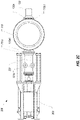
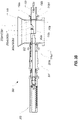
Figures 2A-2C illustrate an isometric view, a cross-sectional side view, and a top view respectively of a retractable center feed injection device in a retracted position; -
Figures 3A-3C illustrate an isometric view, a cross-sectional side view, and a top view respectively of the retractable center feed injection device in an extended position; -
Figure 4 illustrates a detailed view of the interface between an injection nozzle and a feed inlet through which residual oil is fed into a coke drum; and -
Figure 5 illustrates the direction of flow of residual oil through the retractable center feed injection device and into the coke drum. -
Figure 1 generally depicts adelayed coking system 100 that includes a retractable center feed injection device in accordance with embodiments of the present invention. Delayedcoking system 100 includes acoke drum 110 into which heated residual oil can be injected as part of a delayed coking process. A bottom unheadingvalve 120 is coupled to a bottom ofcoke drum 110 and can be opened to allow coke to fall out ofcoke drum 110 after the delayed coking process has completed.Coke drum 110 can be configured to allow afeed inlet 130 and a retractable centerfeed injection device 200 to be coupled to the coke drum on opposing sides of the coke drum. For example,coke drum 110 may include flanges forming openings on opposing sides of the coke drum. In this specification and the claims, the term coke drum should be construed as encompassing the entirety of a coke drum or a component (e.g., a spool) that is coupled to and forms part of the coke drum. For example, in some embodiments,coke drum 110 as described herein can represent a bottom-most portion of a coke drum that can be installed on an existing coke drum. Therefore, the present invention should not be limited to any particular configuration of a coke drum to which the retractable center feed injection device may be coupled. Although it is presently preferable to inject the residual product upward, it will be understood that the resolved product could also be injected in any direction. Additionally, although all of the housing in the preferred embodiments is extended to the drum, it will be appreciated that some minor portions of the housing such as an attachment flange may be located inside the drum. It is preferable to locate as much of the housing outside of the drum as possible. - As was described in the background, various center feed systems exist which could be employed to feed residual oil into
coke drum 110 from a center of the coke drum. However, in each of these prior art center feed systems, the residual oil would be fed through the center feed system. With reference toFigure 1 , this would be akin to feeding the residual oil through the portion of retractable centerfeed injection device 200 that is located outside ofcoke drum 110. In contrast, in accordance with embodiments of the present invention, retractable centerfeed injection device 200 andfeed inlet 130 can be configured to allow residual oil to be fed intocoke drum 110 without ever passing through any portion of retractable centerfeed injection device 200 that is located external to coke drum 110 (e.g., housing 201). This configuration is shown inFigures 2A-3C . - In
Figures 2A-2C , retractable centerfeed injection device 200 is shown in a retracted position, while inFigures 3A-3C , retractable centerfeed injection device 200 is shown in an extended position. While in the extended position, retractable centerfeed injection device 200 can form a channel withfeed inlet 130 through which residual oil can be injected intocoke drum 110. After residual oil has been injected, retractable centerfeed injection device 200 can be returned to the retracted position until it is again desired to inject residual oil (i.e., until the next coking cycle). - Retractable center feed
injection device 200 includes ahousing 201, aninjection nozzle 202 positioned withinhousing 201, and anactuator 203 that is configured to moveinjection nozzle 202 between the retracted position and the extended position. Any suitable type of actuator can be employed, and therefore actuator 203 will not be described in detail. Suffice it to say thatactuator 203 includes a slidable component that couples toinjection nozzle 202 for the purpose of slidinginjection nozzle 202 between the two positions. - Housing 201 can include a
flange 201a by whichhousing 201 is coupled to coke drum 110 (e.g., via flange 110a1 on coke drum 110).Housing 201 may also include a number ofopenings 201b by which the interior ofhousing 201 can be pressurized (e.g., with steam) to thereby prevent the flow of materials from withincoke drum 110 intohousing 201. In other words, the small gap between the outer surface ofinjection nozzle 202 and the inner surface ofhousing 201 can be pressurized to substantially match or approximate the pressure that will exist withincoke drum 110 during the coking process. Additionally,housing 201 may include a number of components/structures that form a seal against the outer surface ofinjection nozzle 202 which allowhousing 201 to be pressurized and also block the flow of materials intohousing 201. - As best shown in
Figure 2B ,injection nozzle 202 can have a length that causes a tip of the injection nozzle to be positioned near opening 110a ofcoke drum 110.Housing 201 may also include a portion that extends beyondflange 201a and into flange 110a1 so that the tip ofhousing 201 is also positioned at ornear opening 110a. The tolerances betweenopening 110a,housing 201, andinjection nozzle 202 can be such that a tight seal is formed atopening 110a thereby preventing the flow of materials out through the junction between flanges 110a1 and 201a. -
Injection nozzle 202 can include achamber 202a positioned at the end of the injection nozzle that inserts intocoke drum 110.Chamber 202a includes an inlet opening 202a1 that is oriented towards and aligned withfeed inlet 130 on the opposing side ofcoke drum 110. In some embodiments, a nozzle seat 202b1 can be coupled at the tip ofinjection nozzle 202 and around inlet opening 202a1. When nozzle seat 202b1 is included, the length ofinjection nozzle 202 as well as the size of nozzle seat 202b1 can be configured such that nozzle seat 202b1 sits at or slightly withinopening 110a wheninjection nozzle 202 is in the retracted position (i.e., nozzle seat 202b1 can be configured to not extend intocoke drum 110 wheninjection nozzle 202 is in the retracted position). The role of this nozzle seat 202b1 will be further described below. However, in some embodiments,injection nozzle 202 may not include nozzle seat 202b1. In such cases, the tip ofinjection nozzle 202 can be configured with a shape that corresponds with the shape of the depicted nozzle seat 202b1. -
Chamber 202a can also include outlet openings 202a2 and 202a3 which are oriented upwardly and spaced from the tip ofinjection nozzle 202 such that openings 202a2 and 202a3 will be positioned at or near a center ofcoke drum 110 wheninjection nozzle 202 is in the extended position. Outlet openings 202a2 and 202a3 can include inserts 202b2 and 202b3 respectively which can be used to direct the flow of residual oil as it exitschamber 202a. In some embodiments, inserts 202b2 and 202b3 can be replaceable to facilitate maintaininginjection nozzle 202. -
Feed inlet 130 can be configured to couple tocoke drum 110 via a flange 110b1 that forms anopening 110b that is aligned withopening 110a.Feed inlet 130 can include aflange 130a that is configured to couple to flange 110b1 and aportion 130b that extends inwardly through flange 110b1 when flange 130a is coupled to flange 110b1. The length ofportion 130b can be configured such that its tip is positioned nearopening 110b. In some embodiments, afeed inlet seat 130c can be coupled to the tip ofportion 130b around opening 130b1. As with nozzle seat 202b1, feedinlet seat 130c can be positioned at or slightly withinopening 110b such that it does not extend intocoke drum 110. In other embodiments, however, feedinlet 130 may not include afeed inlet seat 130c. In such cases, the tip ofportion 130b can be configured with the same shape as that of the depictedfeed inlet seat 130c. - The shapes of nozzle seat 202b1 and feed
inlet seat 130c can correspond to one another such that a seal can be formed when nozzle seat 202b1 is pressed againstfeed inlet seat 130c. This is best shown inFigures 3B and4 . Wheninjection nozzle 202 is slid into the extended position, and due toopenings feed inlet seat 130c (or alternatively, feedinlet seat 130c could be configured to insert into nozzle seat 202b1). Due to the force applied byactuator 203 oninjection nozzle 202, the interface between nozzle seat 202b1 and feedinlet seat 130c will form a seal wheninjection nozzle 202 is in the extended position and residual oil is fed throughchamber 202a. -
Figure 5 illustrates how residual oil supplied throughfeed inlet 130 can enter intochamber 202a through inlet opening 202a1 and then exitchamber 202a via outlet openings 202a2 and 202a3. As indicated, the residual oil never passes through any component of retractable centerfeed injection device 200 that is positioned exterior tocoke drum 110, such as, for example,housing 201. Instead, the residual oil only flows through the portion ofinjection nozzle 202 that is positioned withincoke drum 110. For this reason,housing 201 and the other exterior components of retractable centerfeed injection device 200 need not be designed to accommodate the harsh conditions that would otherwise be created if heated residual oil were flowed through these components. In this way, the design and maintenance of retractable centerfeed injection device 200 is simplified. - In addition to forming a seal, nozzle seat 202b1 and feed
inlet seat 130c can function to simplify the maintenance of retractable centerfeed injection device 200. In particular, both nozzle seat 202b1 and feedinlet seat 130c can be configured to be removable frominjection nozzle 202 andfeed inlet 130 respectively. Therefore, as these seats become worn, the seats alone can be replaced without needing to replaceinjection nozzle 202 and/or feedinlet 130. In fact, due to their design, these seats can be replaced in situ (e.g., by lowering an individual intocoke drum 110 to remove the seats whileinjection nozzle 202 is in the retracted (or at least in a partially retracted) position. - Although it may be preferred to employ one or both of nozzle seat 202b1 and feed
inlet seat 130c, in some embodiments, retractable centerfeed injection device 200 may be designed to include only one or neither of nozzle seat 202b1 or feedinlet seat 130c. As indicated above, when only one or no seats are employed,injection nozzle 202 andfeed inlet 130 can still be configured to couple in a similar manner as described above when both seats are included such that a seal will still be formed wheninjection nozzle 202 is in the extended position. - Another benefit of the design of retractable center
feed injection device 200 is that it allows residual oil to be fed intocoke drum 110 even when the retractable center feed injection device may not be operating properly or may be undergoing external maintenance. For example, if for anyreason injection nozzle 202 cannot be slid in the extended position, residual oil may still be fed throughfeed inlet 130 to thereby fillcoke drum 110. In other words, retractable centerfeed injection device 200 allowscoke drum 110 to be filled via either a center feed or a side feed process. The described embodiments are to be considered in all respects only as illustrative and not restrictive. The scope of the invention is, therefore, indicated by the appended claims rather than by the foregoing description.
Claims (14)
- A retractable center feed injection device (200) for use on a coke drum (110) comprising:a housing (201) configured to couple to a sidewall of a coke drum (110) in alignment with a first opening (110a) in the sidewall;an injection nozzle (202) contained within the housing (201), the injection nozzle (202) having a first end and a second end, the injection nozzle (202) being configured to slide between a retracted position and an extended position in which the first end extends into the coke drum (110); andan actuator (203) that is coupled to the second end of the injection nozzle (202) and configured to slide the injection nozzle (202) between the retracted position and the extended position;a feed inlet (130) configured to couple to the sidewall of the coke drum (110) in alignment with a second opening (110b) in the sidewall, the second opening (110b) being opposite the first opening (110a), the first end of the injection nozzle (202) coupling with the feed inlet (130) when the injection nozzle (202) is in the extended position; andwherein the injection nozzle (202) includes a chamber (202a) having an inlet opening (202a1) that aligns with the feed inlet (130) and one or more outlet openings (202a2, 202a3) that are oriented upwardly such that the residual oil fed through the feed inlet (130) when the injection nozzle (202) is in the extended position flows into the chamber (202a) through the inlet opening (202a1) and out of the chamber (202a) through the one or more outlet openings (202a2, 202a3) with no residual oil passing through the housing (201).
- The retractable center feed injection device (200) of claim 1, wherein the first end of the injection nozzle (202) inserts into the feed inlet (130).
- The retractable center feed injection device (200) of claim 1, wherein the injection nozzle (202) comprises:
a nozzle seat (202b1) coupled to the first end of the injection nozzle (202) around the inlet opening (202a1), the nozzle seat (202b1) configured to couple with the feed inlet (130) when the injection nozzle (202) is in the extended position. - The retractable center feed injection device (200) of claim 3, wherein the inlet opening (202a1) comprises:
a feed inlet seat (130c) positioned at a tip of the feed inlet (130), the feed inlet seat (130c) configured to couple with the nozzle seat (202b1) when the injection nozzle (202) is in the extended position. - The retractable center feed injection device (200) of claim 4, wherein the feed inlet seat (130c) is positioned inside the second opening (110b) such that the feed inlet seat (130c) does not extend into an interior of the coke drum (110), the nozzle seat (202b1) extending into the second opening (110b) when the injection nozzle (202) is in the extended position.
- The retractable center feed injection device (200) of claim 1, wherein the injection nozzle (202) comprises:
a nozzle seat (202b1) coupled to the first end of the injection nozzle (202) around the inlet opening (202a1). - A coke drum center feed system comprising:a coke drum (110) having a sidewall with a first opening (110a) and a second opening (110b) opposite and aligned with the first opening (110a);a feed inlet (130) coupled to the second opening (110b) and configured to feed residual oil into the coke drum (110) via the second opening (110b); anda retractable center feed injection device (200) comprising:a housing (201) coupled to the sidewall in alignment with the first opening (110a);an injection nozzle (202) contained within the housing (201), the injection nozzle (202) having a first end and a second end, the injection nozzle (202) configured to slide between a retracted position in which the first end does not extend through the first opening (110a) into an interior of the coke drum (110) and an extended position in which the injection nozzle (202) extends across the interior of the coke drum (110) to couple the first end with the feed inlet (130), the injection nozzle (202) including a chamber (202a) positioned towards the first end, the chamber (202a) including an inlet opening (202a1) that aligns with the feed inlet (130) and one or more outlet openings (202a2, 202a3) that are oriented upwardly such that the residual oil fed through the feed inlet (130) when the injection nozzle is in the extended position flows into the chamber (202a) via the inlet opening (202a1) and out of the chamber (202a) via the one or more outlet openings (202a2, 202a3); andan actuator (203) for sliding the injection nozzle (202) between the retracted position and the extended position.
- The coke drum center feed system of claim 7, wherein the injection nozzle (202) includes a nozzle seat (202b1) coupled to the first end around the inlet opening (202a1).
- The coke drum center feed system of claim 8, wherein the nozzle seat (202b1) couples with the feed inlet (130).
- The coke drum center feed system of claim 9, wherein the nozzle seat (202b1) inserts into the feed inlet (130).
- The coke drum center feed system of claim 10, wherein the feed inlet (130) includes a feed inlet seat (130c) and the nozzle seat (202b1) inserts into the feed inlet seat (130c) to couple the injection nozzle (202) to the feed inlet (130).
- The coke drum center feed system of claim 9, wherein the feed inlet (130) includes a feed inlet seat (130c) and the nozzle seat (202b1) couples with the feed inlet seat (130c).
- The coke drum center feed system of claim 7, wherein, when the injection nozzle (202) is the in extended position, the outlet openings (202a2, 202a3) are positioned near a center of the interior of the coke drum (110).
- The coke drum center feed system of claim 7, wherein, when the injection nozzle (202) is in the extended position, the chamber (202a) is positioned entirely external to the housing (201).
Priority Applications (1)
| Application Number | Priority Date | Filing Date | Title |
|---|---|---|---|
| HRP20230304TT HRP20230304T1 (en) | 2016-06-17 | 2016-08-15 | Retractable center feed injection device |
Applications Claiming Priority (2)
| Application Number | Priority Date | Filing Date | Title |
|---|---|---|---|
| US15/185,324 US10081766B2 (en) | 2016-06-17 | 2016-06-17 | Retractable center feed injection device |
| PCT/US2016/047068 WO2017218020A1 (en) | 2016-06-17 | 2016-08-15 | Retractable center feed injection device |
Publications (3)
| Publication Number | Publication Date |
|---|---|
| EP3472264A1 EP3472264A1 (en) | 2019-04-24 |
| EP3472264A4 EP3472264A4 (en) | 2020-01-29 |
| EP3472264B1 true EP3472264B1 (en) | 2022-12-28 |
Family
ID=60661202
Family Applications (1)
| Application Number | Title | Priority Date | Filing Date |
|---|---|---|---|
| EP16905670.2A Active EP3472264B1 (en) | 2016-06-17 | 2016-08-15 | Retractable center feed injection device |
Country Status (13)
| Country | Link |
|---|---|
| US (1) | US10081766B2 (en) |
| EP (1) | EP3472264B1 (en) |
| JP (1) | JP6692989B2 (en) |
| KR (1) | KR102165702B1 (en) |
| CN (1) | CN110191939B (en) |
| BR (1) | BR112018076316B1 (en) |
| CA (1) | CA3030825C (en) |
| ES (1) | ES2936814T3 (en) |
| HR (1) | HRP20230304T1 (en) |
| MX (1) | MX2018015868A (en) |
| PL (1) | PL3472264T3 (en) |
| RU (1) | RU2705087C1 (en) |
| WO (1) | WO2017218020A1 (en) |
Families Citing this family (1)
| Publication number | Priority date | Publication date | Assignee | Title |
|---|---|---|---|---|
| US10913899B2 (en) * | 2019-02-11 | 2021-02-09 | Houston Engineering Solutions, Llc | Bottom de-heading device and inlet for coke drum |
Family Cites Families (16)
| Publication number | Priority date | Publication date | Assignee | Title |
|---|---|---|---|---|
| SU150094A1 (en) * | 1961-10-23 | 1961-11-30 | Ф.М. Паненко | Shut-off and control device for loading the liquid pitch from the distribution manifold into the coke oven |
| SU420648A1 (en) * | 1972-05-11 | 1974-03-25 | А. А. Муковников Кемеровский ордена Ленина коксохимический завод | DEVICE FOR AUTOMATIC LOADING OF PECOXIC OVENS BAKER |
| US4043471A (en) * | 1975-08-25 | 1977-08-23 | Battelle Memorial Institute | Method of particle feeding |
| US4100035A (en) * | 1975-10-03 | 1978-07-11 | Continental Oil Company | Apparatus for quenching delayed coke |
| SU829651A1 (en) * | 1979-08-13 | 1981-05-15 | Научно-Исследовательский И Опытно- Конструкторский Институт Автоматизациичерной Металлургии | Device for loading pitch in pitch-coke furnace |
| ATE458798T1 (en) * | 2001-03-12 | 2010-03-15 | Curtiss Wright Flow Control | IMPROVED SYSTEM FOR REMOVING THE BOTTOM OF A COKING CHAMBER |
| US20030127314A1 (en) * | 2002-01-10 | 2003-07-10 | Bell Robert V. | Safe and automatic method for removal of coke from a coke vessel |
| US8702911B2 (en) * | 2003-02-21 | 2014-04-22 | Curtiss-Wright Flow Control Corporation | Center feed system |
| US7115190B2 (en) * | 2003-02-21 | 2006-10-03 | Curtiss-Wright Flow Control Corporation | Tangential dispenser and system for use within a delayed coking system |
| KR100530099B1 (en) * | 2003-12-22 | 2005-11-22 | 재단법인 포항산업과학연구원 | Automatic Coke Oven Gas Nozzle Cleaner for Lime Kilns |
| BRPI0400769B1 (en) * | 2004-03-25 | 2013-05-14 | Injection system for delayed coking drums. | |
| US8545680B2 (en) * | 2009-02-11 | 2013-10-01 | Curtiss-Wright Flow Control Corporation | Center feed system |
| CN104769078B (en) * | 2012-04-30 | 2017-06-09 | 科蒂斯-赖特流体控制公司 | Center Feed System with Removable Insert in Retractable Injection Nozzle |
| ES2707052T3 (en) * | 2012-04-30 | 2019-04-02 | Curtiss Wright Flow Control Corp | Central feed system employing removable inserts in a retractable injection nozzle |
| EP3003684B1 (en) | 2013-05-30 | 2017-08-23 | Discma AG | Injection device comprising a central rod movable in a cleaning position |
| KR101560990B1 (en) * | 2014-12-02 | 2015-10-16 | 주식회사 포스코 | Gas Feeder |
-
2016
- 2016-06-17 US US15/185,324 patent/US10081766B2/en active Active
- 2016-08-15 WO PCT/US2016/047068 patent/WO2017218020A1/en not_active Ceased
- 2016-08-15 CA CA3030825A patent/CA3030825C/en active Active
- 2016-08-15 MX MX2018015868A patent/MX2018015868A/en unknown
- 2016-08-15 CN CN201680088539.4A patent/CN110191939B/en active Active
- 2016-08-15 HR HRP20230304TT patent/HRP20230304T1/en unknown
- 2016-08-15 RU RU2019101212A patent/RU2705087C1/en active IP Right Revival
- 2016-08-15 JP JP2019518369A patent/JP6692989B2/en active Active
- 2016-08-15 BR BR112018076316-0A patent/BR112018076316B1/en active IP Right Grant
- 2016-08-15 EP EP16905670.2A patent/EP3472264B1/en active Active
- 2016-08-15 KR KR1020197001601A patent/KR102165702B1/en active Active
- 2016-08-15 ES ES16905670T patent/ES2936814T3/en active Active
- 2016-08-15 PL PL16905670.2T patent/PL3472264T3/en unknown
Also Published As
| Publication number | Publication date |
|---|---|
| CN110191939A (en) | 2019-08-30 |
| CA3030825A1 (en) | 2017-12-21 |
| EP3472264A1 (en) | 2019-04-24 |
| US20170362510A1 (en) | 2017-12-21 |
| US10081766B2 (en) | 2018-09-25 |
| RU2705087C1 (en) | 2019-11-01 |
| BR112018076316A2 (en) | 2019-03-26 |
| PL3472264T3 (en) | 2023-05-02 |
| CA3030825C (en) | 2022-03-22 |
| JP2019523815A (en) | 2019-08-29 |
| EP3472264A4 (en) | 2020-01-29 |
| MX2018015868A (en) | 2019-12-16 |
| WO2017218020A1 (en) | 2017-12-21 |
| BR112018076316B1 (en) | 2021-10-26 |
| JP6692989B2 (en) | 2020-05-13 |
| KR20190050965A (en) | 2019-05-14 |
| CN110191939B (en) | 2021-04-20 |
| HRP20230304T1 (en) | 2023-05-26 |
| KR102165702B1 (en) | 2020-10-14 |
| ES2936814T3 (en) | 2023-03-22 |
Similar Documents
| Publication | Publication Date | Title |
|---|---|---|
| CN104769078B (en) | Center Feed System with Removable Insert in Retractable Injection Nozzle | |
| EP2396389B1 (en) | Center feed system | |
| CA3030825C (en) | Retractable center feed injection device | |
| CN102333847B (en) | Center Feeding System | |
| EP2844720B1 (en) | Center feed system employing removable inserts in a retractable injection nozzle | |
| DE102012101015A1 (en) | Coke drum, coking drum shut-off valve and method of feeding waste into a coking drum | |
| EP0995573A1 (en) | Injector/mould system for the injection of polymers, silicons or thermosetting material | |
| WO2016096097A1 (en) | Conveyor device for a metal melt in an injection moulding unit |
Legal Events
| Date | Code | Title | Description |
|---|---|---|---|
| REG | Reference to a national code |
Ref country code: HR Ref legal event code: TUEP Ref document number: P20230304T Country of ref document: HR |
|
| STAA | Information on the status of an ep patent application or granted ep patent |
Free format text: STATUS: THE INTERNATIONAL PUBLICATION HAS BEEN MADE |
|
| PUAI | Public reference made under article 153(3) epc to a published international application that has entered the european phase |
Free format text: ORIGINAL CODE: 0009012 |
|
| STAA | Information on the status of an ep patent application or granted ep patent |
Free format text: STATUS: REQUEST FOR EXAMINATION WAS MADE |
|
| 17P | Request for examination filed |
Effective date: 20190116 |
|
| AK | Designated contracting states |
Kind code of ref document: A1 Designated state(s): AL AT BE BG CH CY CZ DE DK EE ES FI FR GB GR HR HU IE IS IT LI LT LU LV MC MK MT NL NO PL PT RO RS SE SI SK SM TR |
|
| AX | Request for extension of the european patent |
Extension state: BA ME |
|
| DAV | Request for validation of the european patent (deleted) | ||
| DAX | Request for extension of the european patent (deleted) | ||
| A4 | Supplementary search report drawn up and despatched |
Effective date: 20200108 |
|
| RIC1 | Information provided on ipc code assigned before grant |
Ipc: B01J 4/00 20060101ALI20191220BHEP Ipc: C10B 31/12 20060101AFI20191220BHEP Ipc: C10B 45/00 20060101ALI20191220BHEP |
|
| STAA | Information on the status of an ep patent application or granted ep patent |
Free format text: STATUS: EXAMINATION IS IN PROGRESS |
|
| 17Q | First examination report despatched |
Effective date: 20211104 |
|
| GRAP | Despatch of communication of intention to grant a patent |
Free format text: ORIGINAL CODE: EPIDOSNIGR1 |
|
| STAA | Information on the status of an ep patent application or granted ep patent |
Free format text: STATUS: GRANT OF PATENT IS INTENDED |
|
| INTG | Intention to grant announced |
Effective date: 20220210 |
|
| RIN1 | Information on inventor provided before grant (corrected) |
Inventor name: LARSEN, GARY Inventor name: KRAUSE, KENNETH Inventor name: LAH, RUBEN F. |
|
| GRAJ | Information related to disapproval of communication of intention to grant by the applicant or resumption of examination proceedings by the epo deleted |
Free format text: ORIGINAL CODE: EPIDOSDIGR1 |
|
| STAA | Information on the status of an ep patent application or granted ep patent |
Free format text: STATUS: EXAMINATION IS IN PROGRESS |
|
| INTC | Intention to grant announced (deleted) | ||
| GRAP | Despatch of communication of intention to grant a patent |
Free format text: ORIGINAL CODE: EPIDOSNIGR1 |
|
| STAA | Information on the status of an ep patent application or granted ep patent |
Free format text: STATUS: GRANT OF PATENT IS INTENDED |
|
| INTG | Intention to grant announced |
Effective date: 20220727 |
|
| GRAS | Grant fee paid |
Free format text: ORIGINAL CODE: EPIDOSNIGR3 |
|
| GRAA | (expected) grant |
Free format text: ORIGINAL CODE: 0009210 |
|
| STAA | Information on the status of an ep patent application or granted ep patent |
Free format text: STATUS: THE PATENT HAS BEEN GRANTED |
|
| AK | Designated contracting states |
Kind code of ref document: B1 Designated state(s): AL AT BE BG CH CY CZ DE DK EE ES FI FR GB GR HR HU IE IS IT LI LT LU LV MC MK MT NL NO PL PT RO RS SE SI SK SM TR |
|
| REG | Reference to a national code |
Ref country code: GB Ref legal event code: FG4D |
|
| REG | Reference to a national code |
Ref country code: CH Ref legal event code: EP |
|
| REG | Reference to a national code |
Ref country code: DE Ref legal event code: R096 Ref document number: 602016077197 Country of ref document: DE |
|
| REG | Reference to a national code |
Ref country code: AT Ref legal event code: REF Ref document number: 1540487 Country of ref document: AT Kind code of ref document: T Effective date: 20230115 |
|
| REG | Reference to a national code |
Ref country code: IE Ref legal event code: FG4D |
|
| REG | Reference to a national code |
Ref country code: ES Ref legal event code: FG2A Ref document number: 2936814 Country of ref document: ES Kind code of ref document: T3 Effective date: 20230322 |
|
| REG | Reference to a national code |
Ref country code: RO Ref legal event code: EPE |
|
| REG | Reference to a national code |
Ref country code: NO Ref legal event code: T2 Effective date: 20221228 |
|
| REG | Reference to a national code |
Ref country code: LT Ref legal event code: MG9D |
|
| PG25 | Lapsed in a contracting state [announced via postgrant information from national office to epo] |
Ref country code: SE Free format text: LAPSE BECAUSE OF FAILURE TO SUBMIT A TRANSLATION OF THE DESCRIPTION OR TO PAY THE FEE WITHIN THE PRESCRIBED TIME-LIMIT Effective date: 20221228 Ref country code: LT Free format text: LAPSE BECAUSE OF FAILURE TO SUBMIT A TRANSLATION OF THE DESCRIPTION OR TO PAY THE FEE WITHIN THE PRESCRIBED TIME-LIMIT Effective date: 20221228 Ref country code: FI Free format text: LAPSE BECAUSE OF FAILURE TO SUBMIT A TRANSLATION OF THE DESCRIPTION OR TO PAY THE FEE WITHIN THE PRESCRIBED TIME-LIMIT Effective date: 20221228 |
|
| REG | Reference to a national code |
Ref country code: NL Ref legal event code: MP Effective date: 20221228 |
|
| REG | Reference to a national code |
Ref country code: AT Ref legal event code: MK05 Ref document number: 1540487 Country of ref document: AT Kind code of ref document: T Effective date: 20221228 |
|
| REG | Reference to a national code |
Ref country code: HR Ref legal event code: T1PR Ref document number: P20230304 Country of ref document: HR |
|
| PG25 | Lapsed in a contracting state [announced via postgrant information from national office to epo] |
Ref country code: RS Free format text: LAPSE BECAUSE OF FAILURE TO SUBMIT A TRANSLATION OF THE DESCRIPTION OR TO PAY THE FEE WITHIN THE PRESCRIBED TIME-LIMIT Effective date: 20221228 Ref country code: LV Free format text: LAPSE BECAUSE OF FAILURE TO SUBMIT A TRANSLATION OF THE DESCRIPTION OR TO PAY THE FEE WITHIN THE PRESCRIBED TIME-LIMIT Effective date: 20221228 Ref country code: GR Free format text: LAPSE BECAUSE OF FAILURE TO SUBMIT A TRANSLATION OF THE DESCRIPTION OR TO PAY THE FEE WITHIN THE PRESCRIBED TIME-LIMIT Effective date: 20230329 |
|
| PG25 | Lapsed in a contracting state [announced via postgrant information from national office to epo] |
Ref country code: NL Free format text: LAPSE BECAUSE OF FAILURE TO SUBMIT A TRANSLATION OF THE DESCRIPTION OR TO PAY THE FEE WITHIN THE PRESCRIBED TIME-LIMIT Effective date: 20221228 |
|
| P01 | Opt-out of the competence of the unified patent court (upc) registered |
Effective date: 20230527 |
|
| PG25 | Lapsed in a contracting state [announced via postgrant information from national office to epo] |
Ref country code: SM Free format text: LAPSE BECAUSE OF FAILURE TO SUBMIT A TRANSLATION OF THE DESCRIPTION OR TO PAY THE FEE WITHIN THE PRESCRIBED TIME-LIMIT Effective date: 20221228 Ref country code: PT Free format text: LAPSE BECAUSE OF FAILURE TO SUBMIT A TRANSLATION OF THE DESCRIPTION OR TO PAY THE FEE WITHIN THE PRESCRIBED TIME-LIMIT Effective date: 20230428 Ref country code: EE Free format text: LAPSE BECAUSE OF FAILURE TO SUBMIT A TRANSLATION OF THE DESCRIPTION OR TO PAY THE FEE WITHIN THE PRESCRIBED TIME-LIMIT Effective date: 20221228 Ref country code: CZ Free format text: LAPSE BECAUSE OF FAILURE TO SUBMIT A TRANSLATION OF THE DESCRIPTION OR TO PAY THE FEE WITHIN THE PRESCRIBED TIME-LIMIT Effective date: 20221228 Ref country code: AT Free format text: LAPSE BECAUSE OF FAILURE TO SUBMIT A TRANSLATION OF THE DESCRIPTION OR TO PAY THE FEE WITHIN THE PRESCRIBED TIME-LIMIT Effective date: 20221228 |
|
| REG | Reference to a national code |
Ref country code: HR Ref legal event code: ODRP Ref document number: P20230304 Country of ref document: HR Payment date: 20230727 Year of fee payment: 8 |
|
| PG25 | Lapsed in a contracting state [announced via postgrant information from national office to epo] |
Ref country code: SK Free format text: LAPSE BECAUSE OF FAILURE TO SUBMIT A TRANSLATION OF THE DESCRIPTION OR TO PAY THE FEE WITHIN THE PRESCRIBED TIME-LIMIT Effective date: 20221228 Ref country code: IS Free format text: LAPSE BECAUSE OF FAILURE TO SUBMIT A TRANSLATION OF THE DESCRIPTION OR TO PAY THE FEE WITHIN THE PRESCRIBED TIME-LIMIT Effective date: 20230428 Ref country code: AL Free format text: LAPSE BECAUSE OF FAILURE TO SUBMIT A TRANSLATION OF THE DESCRIPTION OR TO PAY THE FEE WITHIN THE PRESCRIBED TIME-LIMIT Effective date: 20221228 |
|
| REG | Reference to a national code |
Ref country code: DE Ref legal event code: R097 Ref document number: 602016077197 Country of ref document: DE |
|
| PG25 | Lapsed in a contracting state [announced via postgrant information from national office to epo] |
Ref country code: DK Free format text: LAPSE BECAUSE OF FAILURE TO SUBMIT A TRANSLATION OF THE DESCRIPTION OR TO PAY THE FEE WITHIN THE PRESCRIBED TIME-LIMIT Effective date: 20221228 |
|
| PLBE | No opposition filed within time limit |
Free format text: ORIGINAL CODE: 0009261 |
|
| STAA | Information on the status of an ep patent application or granted ep patent |
Free format text: STATUS: NO OPPOSITION FILED WITHIN TIME LIMIT |
|
| 26N | No opposition filed |
Effective date: 20230929 |
|
| PG25 | Lapsed in a contracting state [announced via postgrant information from national office to epo] |
Ref country code: SI Free format text: LAPSE BECAUSE OF FAILURE TO SUBMIT A TRANSLATION OF THE DESCRIPTION OR TO PAY THE FEE WITHIN THE PRESCRIBED TIME-LIMIT Effective date: 20221228 |
|
| PG25 | Lapsed in a contracting state [announced via postgrant information from national office to epo] |
Ref country code: MC Free format text: LAPSE BECAUSE OF FAILURE TO SUBMIT A TRANSLATION OF THE DESCRIPTION OR TO PAY THE FEE WITHIN THE PRESCRIBED TIME-LIMIT Effective date: 20221228 |
|
| REG | Reference to a national code |
Ref country code: CH Ref legal event code: PL |
|
| PG25 | Lapsed in a contracting state [announced via postgrant information from national office to epo] |
Ref country code: MC Free format text: LAPSE BECAUSE OF FAILURE TO SUBMIT A TRANSLATION OF THE DESCRIPTION OR TO PAY THE FEE WITHIN THE PRESCRIBED TIME-LIMIT Effective date: 20221228 |
|
| PG25 | Lapsed in a contracting state [announced via postgrant information from national office to epo] |
Ref country code: LU Free format text: LAPSE BECAUSE OF NON-PAYMENT OF DUE FEES Effective date: 20230815 |
|
| PG25 | Lapsed in a contracting state [announced via postgrant information from national office to epo] |
Ref country code: LU Free format text: LAPSE BECAUSE OF NON-PAYMENT OF DUE FEES Effective date: 20230815 Ref country code: CH Free format text: LAPSE BECAUSE OF NON-PAYMENT OF DUE FEES Effective date: 20230831 |
|
| REG | Reference to a national code |
Ref country code: IE Ref legal event code: MM4A |
|
| PG25 | Lapsed in a contracting state [announced via postgrant information from national office to epo] |
Ref country code: IE Free format text: LAPSE BECAUSE OF NON-PAYMENT OF DUE FEES Effective date: 20230815 |
|
| PG25 | Lapsed in a contracting state [announced via postgrant information from national office to epo] |
Ref country code: IE Free format text: LAPSE BECAUSE OF NON-PAYMENT OF DUE FEES Effective date: 20230815 Ref country code: FR Free format text: LAPSE BECAUSE OF NON-PAYMENT OF DUE FEES Effective date: 20230831 |
|
| REG | Reference to a national code |
Ref country code: HR Ref legal event code: ODRP Ref document number: P20230304 Country of ref document: HR Payment date: 20240731 Year of fee payment: 9 |
|
| PG25 | Lapsed in a contracting state [announced via postgrant information from national office to epo] |
Ref country code: BG Free format text: LAPSE BECAUSE OF FAILURE TO SUBMIT A TRANSLATION OF THE DESCRIPTION OR TO PAY THE FEE WITHIN THE PRESCRIBED TIME-LIMIT Effective date: 20221228 |
|
| PG25 | Lapsed in a contracting state [announced via postgrant information from national office to epo] |
Ref country code: BG Free format text: LAPSE BECAUSE OF FAILURE TO SUBMIT A TRANSLATION OF THE DESCRIPTION OR TO PAY THE FEE WITHIN THE PRESCRIBED TIME-LIMIT Effective date: 20221228 |
|
| PG25 | Lapsed in a contracting state [announced via postgrant information from national office to epo] |
Ref country code: CY Free format text: LAPSE BECAUSE OF FAILURE TO SUBMIT A TRANSLATION OF THE DESCRIPTION OR TO PAY THE FEE WITHIN THE PRESCRIBED TIME-LIMIT; INVALID AB INITIO Effective date: 20160815 |
|
| PG25 | Lapsed in a contracting state [announced via postgrant information from national office to epo] |
Ref country code: HU Free format text: LAPSE BECAUSE OF FAILURE TO SUBMIT A TRANSLATION OF THE DESCRIPTION OR TO PAY THE FEE WITHIN THE PRESCRIBED TIME-LIMIT; INVALID AB INITIO Effective date: 20160815 |
|
| REG | Reference to a national code |
Ref country code: HR Ref legal event code: ODRP Ref document number: P20230304 Country of ref document: HR Payment date: 20250730 Year of fee payment: 10 |
|
| PGFP | Annual fee paid to national office [announced via postgrant information from national office to epo] |
Ref country code: ES Payment date: 20250901 Year of fee payment: 10 |
|
| PGFP | Annual fee paid to national office [announced via postgrant information from national office to epo] |
Ref country code: DE Payment date: 20250724 Year of fee payment: 10 |
|
| PGFP | Annual fee paid to national office [announced via postgrant information from national office to epo] |
Ref country code: NO Payment date: 20250725 Year of fee payment: 10 |
|
| PGFP | Annual fee paid to national office [announced via postgrant information from national office to epo] |
Ref country code: IT Payment date: 20250723 Year of fee payment: 10 Ref country code: TR Payment date: 20250728 Year of fee payment: 10 Ref country code: PL Payment date: 20250725 Year of fee payment: 10 |
|
| PGFP | Annual fee paid to national office [announced via postgrant information from national office to epo] |
Ref country code: BE Payment date: 20250723 Year of fee payment: 10 Ref country code: GB Payment date: 20250725 Year of fee payment: 10 |
|
| PGFP | Annual fee paid to national office [announced via postgrant information from national office to epo] |
Ref country code: HR Payment date: 20250730 Year of fee payment: 10 |
|
| PGFP | Annual fee paid to national office [announced via postgrant information from national office to epo] |
Ref country code: RO Payment date: 20250813 Year of fee payment: 10 |