EP3472079B1 - Palettier- und/oder depalettiersystem von waren mit drohnen - Google Patents
Palettier- und/oder depalettiersystem von waren mit drohnen Download PDFInfo
- Publication number
- EP3472079B1 EP3472079B1 EP17736765.3A EP17736765A EP3472079B1 EP 3472079 B1 EP3472079 B1 EP 3472079B1 EP 17736765 A EP17736765 A EP 17736765A EP 3472079 B1 EP3472079 B1 EP 3472079B1
- Authority
- EP
- European Patent Office
- Prior art keywords
- handling
- packs
- drone
- pallet
- stations
- Prior art date
- Legal status (The legal status is an assumption and is not a legal conclusion. Google has not performed a legal analysis and makes no representation as to the accuracy of the status listed.)
- Active
Links
Images


Classifications
-
- B—PERFORMING OPERATIONS; TRANSPORTING
- B65—CONVEYING; PACKING; STORING; HANDLING THIN OR FILAMENTARY MATERIAL
- B65G—TRANSPORT OR STORAGE DEVICES, e.g. CONVEYORS FOR LOADING OR TIPPING, SHOP CONVEYOR SYSTEMS OR PNEUMATIC TUBE CONVEYORS
- B65G61/00—Use of pick-up or transfer devices or of manipulators for stacking or de-stacking articles not otherwise provided for
-
- B—PERFORMING OPERATIONS; TRANSPORTING
- B64—AIRCRAFT; AVIATION; COSMONAUTICS
- B64U—UNMANNED AERIAL VEHICLES [UAV]; EQUIPMENT THEREFOR
- B64U10/00—Type of UAV
- B64U10/10—Rotorcrafts
- B64U10/13—Flying platforms
-
- G—PHYSICS
- G05—CONTROLLING; REGULATING
- G05D—SYSTEMS FOR CONTROLLING OR REGULATING NON-ELECTRIC VARIABLES
- G05D1/00—Control of position, course, altitude or attitude of land, water, air or space vehicles, e.g. using automatic pilots
- G05D1/02—Control of position or course in two dimensions
- G05D1/0202—Control of position or course in two dimensions specially adapted to aircraft
-
- G—PHYSICS
- G05—CONTROLLING; REGULATING
- G05D—SYSTEMS FOR CONTROLLING OR REGULATING NON-ELECTRIC VARIABLES
- G05D1/00—Control of position, course, altitude or attitude of land, water, air or space vehicles, e.g. using automatic pilots
- G05D1/10—Simultaneous control of position or course in three dimensions
- G05D1/101—Simultaneous control of position or course in three dimensions specially adapted for aircraft
- G05D1/104—Simultaneous control of position or course in three dimensions specially adapted for aircraft involving a plurality of aircrafts, e.g. formation flying
-
- G—PHYSICS
- G08—SIGNALLING
- G08G—TRAFFIC CONTROL SYSTEMS
- G08G5/00—Traffic control systems for aircraft
- G08G5/50—Navigation or guidance aids
- G08G5/55—Navigation or guidance aids for a single aircraft
-
- G—PHYSICS
- G08—SIGNALLING
- G08G—TRAFFIC CONTROL SYSTEMS
- G08G5/00—Traffic control systems for aircraft
- G08G5/50—Navigation or guidance aids
- G08G5/57—Navigation or guidance aids for unmanned aircraft
-
- B—PERFORMING OPERATIONS; TRANSPORTING
- B64—AIRCRAFT; AVIATION; COSMONAUTICS
- B64U—UNMANNED AERIAL VEHICLES [UAV]; EQUIPMENT THEREFOR
- B64U2101/00—UAVs specially adapted for particular uses or applications
- B64U2101/60—UAVs specially adapted for particular uses or applications for transporting passengers; for transporting goods other than weapons
-
- B—PERFORMING OPERATIONS; TRANSPORTING
- B65—CONVEYING; PACKING; STORING; HANDLING THIN OR FILAMENTARY MATERIAL
- B65G—TRANSPORT OR STORAGE DEVICES, e.g. CONVEYORS FOR LOADING OR TIPPING, SHOP CONVEYOR SYSTEMS OR PNEUMATIC TUBE CONVEYORS
- B65G2201/00—Indexing codes relating to handling devices, e.g. conveyors, characterised by the type of product or load being conveyed or handled
- B65G2201/02—Articles
- B65G2201/0267—Pallets
Definitions
- the present invention relates to a palletizing and/or depalletizing system of goods.
- palletizing is meant the action of arranging packs or goods on top of pallets, e.g. stacked on top of one another; at the same time, by the term depalletizing is meant the action of picking up packs, or goods previously palletized on pallets.
- pallets or platforms In the particular field of the handling and transport of goods packaged e.g. inside of packs, packages, bags or the like, the use is known of pallets or platforms, more commonly known as pallets, generally made of wood, plastic, metal or pressed chipboard.
- the pallets are used to transport packs arranged on the pallets themselves and packed to obtain palletized packs that can be logistically managed for storage in warehouses or shipment or placing on the market.
- the palletizing and/or depalletizing systems of known type generally comprise automated anthropomorphic robots interposed between a first handling station and a second handling station and adapted to handle packs between the first handling station and the second handling station, or vice versa.
- the automated anthropomorphic robots of known type have an articulated arm provided with an extremity fitted on a rotating platform for the movement of the arm along four movement axes.
- the other extremity of the articulated arm of the automated anthropomorphic robot has a gripper, if necessary rotatable around its own axis, by means of which the packs to be handled are picked up.
- the first handling station is arranged at an industrial machine adapted to package and obtain packs
- the second handling station is adapted to support and move the pallets on which the automated anthropomorphic robots place the packs coming from the first handling station.
- the second handling station is adapted, in turn, to handle the pallets loaded with the packs and afterwards packaged for relative logistics management.
- the automated anthropomorphic robots are adapted to transfer the packs arranged on the first handling station on top of the pallets arranged on the second handling station so as to stack such packs, e.g., the one on the other or according to different layouts, to obtain the required packaging.
- the automated anthropomorphic robots are adapted to pick up the packs arranged on the pallets conveyed on the second handling station and to displace such packs onto the first handling station.
- such automated anthropomorphic robots are adapted to unwrap the packages for the pickup and transfer of the packs contained in them from one handling station to another.
- the main drawback is tied to the fact that the operation of the stations of known type is not very practical due to their structural complexity, and to the large overall dimensions of the automated anthropomorphic robots positioned on the ground, with consequent need for large spaces in which to position such stations.
- Another drawback is tied to any malfunctions or faults affecting one or more of the appliances making up the stations of known type which require the entire station to be stopped with consequent interruption of the production process until such malfunctions or faults have been completely remedied.
- Yet another drawback is tied to the lack of production efficiency and the long time required for palletizing/depalletizing the packs in the cases wherein the distance between the first handling station and the second handling station is great, or in case of large quantities of packs to be palletized/depalletized.
- the pack handling operations are particularly complex in the cases when the packs themselves have to be moved between the first and the second handling stations arranged misaligned the one with the other.
- the main aim of the present invention is to provide a palletizing/depalletizing station of goods which has poor structural complexity and small overall dimensions.
- One object of the present invention is to provide a palletizing/depalletizing station of goods that permits cutting slowdown in production in cases of malfunctions or faults with a consequent reduction in the costs to be borne by the customer for the assistance and maintenance jobs.
- Another object of the present invention is to provide a palletizing/depalletizing station of goods which permits maximizing production efficiency and cutting the time needed for the palletizing/depalletizing operations, in particular in cases of handling large quantities of packs, and simplifying the management of pack movement between handling stations which are misaligned the one with the other.
- Another object of the present invention is to provide a palletizing/depalletizing system of goods which allows to overcome the mentioned drawbacks of the prior art within the scope of a simple, rational, easy, effective to use and low cost solution.
- reference numeral 1 globally indicated with reference numeral 1 is a palletizing and/or depalletizing system of goods.
- palletizing is meant the operation for the orderly arrangement of a plurality of packs or the like above a pallet, e.g., placed side by side and/or stacked on top of one another on the pallet itself so they are ready for shipment.
- depalletizing is meant the operation of picking up the packs orderly arranged above the pallet.
- the system 1 comprises:
- the system 1 comprises a single first handling station 2 and a single second handling station 4.
- system 1 comprises a plurality of first handling stations 2 and a plurality of second handling stations 4.
- the handling stations 2, 4 are fastened to the ground and are provided with a conveyor belt, or a roller element, which permits the packs 3 arranged on them to move forwards.
- the first handling station 2 is adapted to move packs 3, coming for example from an industrial production line by means of which is achieved the packaging of the packs themselves, of the type of rolls of paper or the like, towards the transfer means 6.
- the second handling station 4 is adapted to support one or more pallets 5 on which the packs 3 to be palletized are arranged by means of the transfer means 6 or, alternatively, the packs 3 to be depalletized are picked up.
- the pallet 5 and the packs 3 arranged on it are moved by means of the second handling station 4 and placed, for example, in specific storage warehouses for logistics management and relative shipment.
- the transfer means 6 comprise a drone having a gripper 7 adapted to grip/release the packs 3 and movable along an aerial trajectory A for transferring the packs 3 between the handling stations 2, 4.
- aerial trajectory is meant one or more different paths which the drone 6 covers in flight in the air space which separates the handling stations 2, 4.
- the system 1 comprises a reticular element 8 fastened to the ground and arranged at a predefined distance from the ground itself and adapted to define a safety area, interposed between the ground and the reticular element 8 and devoid of the movement of the drone 6 in its interior, and a work area, arranged on top of the reticular element 8 and inside which the drone 6 is movable in flight along the aerial trajectory A.
- the safety area is adapted to the safe transit of the operators between the handling stations 2, 4, protecting the operator during such transit and keeping him/her safe from any collisions due to flight problems affecting the drone 6.
- the aerial trajectory A is defined between the first handling station 2 and the second handling station 4, and vice versa, and extends substantially on top of the reticular element 8 in the work area.
- system 1 comprises a plurality of reticular elements 8 arranged in the air space between one of the first handling stations 2 and one of the second handling stations 4 aligned the one with the other.
- the transfer means 6 are provided with a single drone, but it cannot be ruled out that the transfer means 6 comprise a plurality of drones.
- each drone 6 covers an aerial trajectory A which defines the path for the movement of the packs 3 from one of the first handling stations 2 to one of the second handling stations 4 or vice versa.
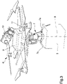
- the drone 6 comprises a base frame 9, adapted to support the gripper 7, and a navigation system 10, 11 adapted to the navigation and the movement of the drone 6 along the aerial trajectory A.
- the drone 6 is arranged in a reference position in which the base frame 9 is substantially horizontal and parallel to the ground.
- the base frame 9 comprises a supporting surface, which in the reference position is facing the ground, with which the gripper 7 is associated.
- the gripper 7 extends overhanging towards the ground with respect to the supporting surface.
- the gripper 7 is movable in rotation around a relative axis of rotation B, thus providing a further degree of freedom for the movement of the flying drone 6.
- this axis of rotation B is substantially transverse to the base frame 9.
- the drone 6 comprises movement means associated with the base frame 9 and which are adapted to support the gripper 7 for the movement of the gripper itself along a direction substantially parallel to the axis of rotation B, in such a way that the gripper 7 has freedom of movement close to/away from the base frame 9.
- the gripper 7 comprises a pair of arm elements 7a switchable between a grip configuration, wherein the arm elements 7a are approached to each other for the grip of one of the packs 3 arranged on one of the handling stations 2, 4, and a release configuration, wherein the arm elements 7a are moved away from each other for the release of the pack 3 on the other of the handling stations 2, 4.
- the drone 6 is provided with a single gripper 7, but alternative embodiments cannot however be ruled out wherein the drone 6 is provided with a plurality of grippers 7 associated with the supporting surface of the base frame 9.
- the grippers 7 are suitably spaced apart to one another so that, in the grip configuration, the packs 3 are moved away from one another so as to avoid any collisions between the packs themselves.
- the drone 6 is movable along a plurality of movement axes in three-dimensional space so that the aerial trajectory A covered between two handling stations 2, 4 has a curvilinear pattern that extends in the air space comprised between the first handling station 2 and the second handling station 4.
- the drone 6 therefore has degrees of freedom of movement with respect to the three movement axes, i.e., the drone 6 can rotate around each of the movement axes in order to vary its orientation with respect to the reference position.
- the system 1 is switchable between:
- the drone 6 is movable in flight and covers the path defined by the aerial trajectory A that develops in the work area and that connects the handling stations 2, 4 to each other.
- the navigation system 10, 11 comprises:
- the management unit is an electronic unit for the automatic control of the movement of the drone 6 which can be suitably configured and programmed by the operator according to the required flight needs.
- the management unit be an electronic unit for the control of the movement of the drone 6 having manual command means whereby the operator can manually regulate the operation of the management unit itself.
- management unit is operatively connected to the gripper 7 and is adapted to switch between the grip configuration and the release configuration and vice versa.
- the driving device is provided with at least one of a GPS and/or LPS unit, telemetric devices, optical and/or laser devices each of which is operatively connected to the management unit for the movement and guide of the drone 6 along the aerial trajectory A according to the characteristics and the obstacles present in the space surrounding the drone 6 and along the aerial trajectory A.
- a GPS and/or LPS unit telemetric devices, optical and/or laser devices each of which is operatively connected to the management unit for the movement and guide of the drone 6 along the aerial trajectory A according to the characteristics and the obstacles present in the space surrounding the drone 6 and along the aerial trajectory A.
- the driving device comprises both telemetric devices, optical or laser devices and at least one of a GPS and/or LPS unit, operatively connected together and to the management unit so that the movement of the drone 6 between the handling stations 2, 4 follows the path of the aerial trajectory A as precisely as possible.
- the LPS unit is adapted to provide the management unit with the coordinates to guide the drone 6 with reference to the work area only.
- the driving device can be configured by an operator by means of the management unit so as to define the aerial trajectory A which the drone 6 has to cover.
- the image acquisition means 10 are selected from at least one camera and at least one 3D vision sensor.
- the image acquisition means 10 comprise a camera 10 associated with the base frame 9 by means of which the photographic frames are taken of the space surrounding the drone 6.
- the management unit is adapted to process such photographic frames taken using the camera 10 to identify the packs 3 and/or the pallet 5 arranged on the handling stations 2, 4.
- the image acquisition means 10 comprise one or more 3D vision sensors adapted to detect 3D scenes of the space surrounding the drone 6.
- the management unit is therefore adapted to regulate the driving device according to the precise position of the pallets 5 and of the packs 3 obtained by means of the processing of the photographic frames so as to recalculate and/or correct the aerial trajectory A which the drone 6 has to cover for the correct identification of the pallets 5 and of the packs 3, in the event of the aerial trajectory A pre-set in the driving device being different to the aerial trajectory A which the drone 6 actually has to cover.
- the detection means 11 comprise at least one of a proximity sensor and a proximity remote sensing device.
- the detection means 11 comprise a plurality of proximity sensors associated with the base frame 9 in the proximity of the perimeter sides of the supporting surface.
- the proximity sensors 11 are selected from: laser proximity sensors, infrared proximity sensors, ultrasonic proximity sensors, microwave proximity sensors and electromagnetic proximity sensors.
- each proximity sensor 11 has emitting means for emitting electromagnetic waves within a pre-defined space, variable according to the type of proximity sensor itself, and means of detection of the electromagnetic waves reflected by the ground, by the handling stations 2, 4, by the packs 3 and by the pallets 5 arranged on the handling stations 2, 4 which are located in the area inside the range of operation of the emitting means themselves.
- the selected proximity sensor 11 is a laser proximity sensor in which the emitting means are of the type of a laser emitting infrared or visible light radiation.
- the detection means 11 comprise, in addition to the proximity sensor, also at least one proximity remote sensing device.
- the proximity remote sensing device is adapted to obtain information on the space and on the surrounding objects and spaced apart from the proximity sensing device itself by means of the measuring of the emitted, reflected or transmitted electromagnetic radiations, which interact with such surfaces of interest.
- such proximity remote sensing device is adapted to detect the information which permits obtaining the data relating to the coordinates of the aerial trajectory A which has to be covered by the drone 6.
- the information read by the proximity remote sensing device is processed by the management unit, which in turn is adapted to regulate the driving device to obtain the coordinates relating to the correct aerial trajectory A which the drone 6 has to cover.
- the system 1 comprises signaling means 12 operatively connected to the detection means 11 and adapted to reflect the electromagnetic radiations emitted by the proximity sensors 11 arranged at the handling stations 2, 4 and in the space interposed between the handling stations 2, 4, or along the path that the drone 6 has to cover between the first handling station 2 and the second handling station 4.
- the signaling means 12 are arranged in the proximity of the handling stations 2, 4 so as to define delimiting areas which allow the navigation system 10, 11 to carry out a simple detection of the handling stations themselves.
- the signaling means 12 are associated above the reticular element 8 in pre-established positions so as to keep the drone 6 at a distance from the reticular element 8 and prevent these colliding.
- the drone 6 moves close to the first handling station 2 to grip one of the packs 3 sliding on the corresponding conveyor belt.
- the light radiation emitted by the proximity sensors 11 is reflected by the signaling means 12 and such reflected light radiation is detected by the proximity sensors 11 and processed by the management unit for comparison and control with the position relating to the first handling station 2 set in the aerial trajectory A.
- the management unit reconfigures the driving device so as to correct the aerial trajectory itself.
- the camera 10 takes the photographic frames and the management unit processes such frames to identify the packs 3.
- the management unit is adapted to switch the arm elements 7a between the release configuration and the grip configuration for gripping the pack 3.
- the drone 6 flies away from the first handling station 2 and covers the aerial trajectory A, the coordinates of which are pre-set in the driving device and is detected by means of the signaling means 12 arranged at the reticular element 8.
- the drone 6 flies within the work area and at a distance from the reticular element 8 such as to avoid any collision with the reticular element itself.
- the drone 6 detects the signaling means 12 which delimit the second handling station 4 and the camera 10 detects the position of the pallet 5 arranged on the conveyor belt.
- the drone 6 moves close to the pallet 5 and the management unit is adapted to pilot the gripper 7 in the switch between the grip configuration and the release configuration to rest the pack 3 above the pallet 5.
- Such palletizing configuration of the system 1 is repeated for a number of cycles equal to the number of packs 3 to be conveyed from the handling station 2 to the handling station 4 until the packs are arranged in an orderly manner above the pallet 5.
- the operating mode of the system 1 in the depalletizing configuration is substantially similar to the palletizing configuration.
- the drone 6 is adapted to pick up each of the packs 3 arranged on the pallet 5 and to fly from the second handling station 4 to the first handling station 2 along the aerial trajectory A to transport such packs 3 to the first handling station 2.
- the system made this way is without the way stations in the event of the goods having to be transported between first and second stations which are misaligned the one with the other.
- the system made this way has low costs and a reduction of the assistance and maintenance costs to be borne by the customer inasmuch as, in the case of a breakdown of one or more drones, only the drones which are involved in the malfunctions need be repaired, and the other drones can be kept operating thereby preventing any interruption of the production process.
Landscapes
- Engineering & Computer Science (AREA)
- Aviation & Aerospace Engineering (AREA)
- Physics & Mathematics (AREA)
- General Physics & Mathematics (AREA)
- Remote Sensing (AREA)
- Radar, Positioning & Navigation (AREA)
- Automation & Control Theory (AREA)
- Mechanical Engineering (AREA)
- Warehouses Or Storage Devices (AREA)
- Lubricants (AREA)
Claims (10)
- Palettier- und/oder Depalettiersystem (1) von Packungen (3) oder Waren, umfassend:- mindestens eine erste Handhabungsstation (2) für eine Vielzahl von zu palettierenden/ depalettierenden Packungen (3), wobei die mindestens eine erste Handhabungsstation (2) am Boden befestigt und mit einem Förderband oder einem Rollenelement versehen ist, das eine Vorwärtsbewegung der darauf angeordneten Packungen (3) ermöglicht;- mindestens eine zweite Handhabungsstation (4);- mindestens eine Palette (5), die an der mindestens einen zweiten Handhabungsstation (4) angeordnet ist, wobei die mindestens eine Palette (5) ausgebildet ist, die zu palettierenden/ depalettierenden Packungen (3) zu tragen;- Beförderungsmittel (6) der zu palettierenden/ depalettierenden Packungen (3) zwischen der mindestens einen ersten Handhabungsstation (2) und der mindestens einen zweiten Handhabungsstation (4), wobei die Beförderungsmittel (6) mindestens eine Drohne (6) mit mindestens einem Greifer (7) umfassen, der zum Greifen/ Freigeben der zu palettierenden/ depalettierenden Packungen (3) geeignet ist, wobei die Drohne (6) entlang mindestens einer Flugbahn (A) beweglich ist, um die zu palettierenden/ depalettierenden Packungen (3) zwischen der mindestens einen ersten Handhabungsstation (2) und der mindestens einen zweiten Handhabungsstation (4) zu befördern;dadurch gekennzeichnet, dass die mindestens eine zweite Handhabungsstation (4) am Boden befestigt und mit einem Förderband oder einem Rollenelement versehen ist, das die mindestens eine Palette (5) trägt und es der mindestens einen darauf angeordneten Palette (5) ermöglicht, sich vorwärts zu bewegen, und dass das Palettier- und/oder Depalettiersystem (1) mindestens ein netzförmiges Element (8) umfasst, das in einem vordefinierten Abstand vom Boden angeordnet und ausgebildet ist, mindestens einen Sicherheitsbereich, der zwischen dem Boden und dem netzartigen Element (8) angeordnet ist und in dem die Drohne (6) nicht gehandhabt werden kann, und mindestens einen Arbeitsbereich zu definieren, der oberhalb des netzartigen Elements (8) angeordnet ist und in dem die Drohne (6) entlang der Flugbahn (A) beweglich ist, wobei die Flugbahn (A) zwischen der mindestens einen ersten Handhabungsstation (2) und der mindestens einen zweiten Handhabungsstation (4) und umgekehrt definiert ist und sich im Wesentlichen oberhalb des netzartigen Elements (8) in dem Arbeitsbereich erstreckt.
- System (1) nach Anspruch 1, dadurch gekennzeichnet, dass die Drohne (6) mindestens einen Grundrahmen (9), der ausgebildet ist, den Greifer (7) zu tragen, und mindestens ein Navigationssystem (10, 11) umfasst, das für die Navigation und die Handhabung der Drohne (6) entlang der Flugbahn (A) ausgebildet ist.
- System (1) nach Anspruch 2, dadurch gekennzeichnet, dass der Greifer (7) um eine relative Drehachse (B) drehbar ist, wobei die Drehachse (B) im Wesentlichen quer zu dem Grundrahmen (9) verläuft.
- System (1) nach einem oder mehreren der vorhergehenden Ansprüche, dadurch gekennzeichnet, dass der Greifer (7) mindestens ein Paar Armelemente (7a) umfasst, die zwischen einer Greifkonfiguration, in der die Armelemente (7a) zum Greifen mindestens einer der auf einer der Handhabungsstationen (2, 4) angeordneten Packungen (3) aufeinander zubewegt sind, und einer Freigabekonfiguration, in der die Armelemente (7a) zum Freigeben der Packung (3) auf der anderen der Handhabungsstationen (2, 4) voneinander wegbewegt sind, umschaltbar sind.
- System (1) nach einem oder mehreren der vorhergehenden Ansprüche, dadurch gekennzeichnet, dass es Signalisierungsmittel (12) umfasst, die betriebsmäßig mit dem Navigationssystem (10, 11) verbunden sind und an mindestens einer der Handhabungsstationen (2, 4) und in dem zwischen den Handhabungsstationen (2, 4) angeordneten Raum angeordnet sind, um die Flugbahn (A) zu definieren, wobei die Signalisierungsmittel (12) ausgebildet sind, die Handhabungsstationen (2, 4) und die Flugbahn (A) zu signalisieren.
- System (1) nach Anspruch 5, dadurch gekennzeichnet, dass das Navigationssystem (10, 11) mindestens eines der folgenden Elemente umfasst:- eine Antriebsvorrichtung, die ausgebildet ist, den Pfad zu speichern, der die Flugbahn (A) definiert, und die Drohne (6) bei der Handhabung entlang der Flugbahn (A) zwischen einer der Handhabungsstationen (2, 4) und der anderen der Handhabungsstationen (2, 4) zu steuern, wobei die Antriebsvorrichtung dem Grundrahmen (9) zugeordnet ist;- Bilderfassungsmittel (10), die geeignet sind, Bilder zu erfassen, die für den Bereich um die Drohne (6) herum relevant sind, um die Packungen (3) und die Palette (5) zu erfassen, wobei die Bilderfassungsmittel (10) dem Grundrahmen (9) zugeordnet sind;- Detektionsmittel (11), die betriebsmäßig mit den Signalisierungsmitteln (12) verbunden und ausgebildet sind, die Position der Handhabungsstationen (2, 4) und die Flugbahn (A) zu detektieren;- mindestens eine Verwaltungseinheit, die betriebsmäßig mit der Antriebsvorrichtung, den Bilderfassungsmitteln (10) und den Detektionsmitteln (11) verbunden und ausgebildet ist, die Drohne (6) entlang der Flugbahn (A) zu steuern.
- System (1) nach Anspruch 6, dadurch gekennzeichnet, dass die Bilderfassungsmittel (10) mindestens eine Kamera oder 3D-Vision-Sensoren umfassen.
- System (1) nach Anspruch 6 oder 7, dadurch gekennzeichnet, dass die Detektionsmittel (11) mindestens einen Näherungssensor oder mindestens eine entfernt angeordnete Sensorvorrichtung zum Erfassen von Annäherungen umfassen.
- System (1) nach Anspruch 8, dadurch gekennzeichnet, dass der Näherungssensor (11) ausgewählt ist aus: Laser-Näherungssensoren, Infrarot-Näherungssensoren, Ultraschall-Näherungssensoren, Mikrowellen-Näherungssensoren und elektromagnetischen Näherungssensoren.
- System (1) nach einem oder mehreren der vorhergehenden Ansprüche, dadurch gekennzeichnet, dass es umschaltbar ist zwischen:- einer Palettierkonfiguration, in der die Drohne (6) ausgebildet ist, die Packungen (3) von einer der Handhabungsstationen (2, 4) ohne die Palette (5) aufzunehmen und die auf der Palette (5) gestapelten Packungen (3) zu tragen, wobei die Palette (5) auf der anderen der Handhabungsstationen (2, 4) angeordnet ist; und- einer Depalettierungskonfiguration, bei der die Drohne (6) ausgebildet ist, die an einer der Handhabungsstationen (2, 4) angeordneten Packungen (3) aufzunehmen und die Packungen (3) an der anderen der Handhabungsstationen (2, 4) ohne die Palette (5) zu tragen.
Applications Claiming Priority (2)
| Application Number | Priority Date | Filing Date | Title |
|---|---|---|---|
| ITUA2016A004478A ITUA20164478A1 (it) | 2016-06-17 | 2016-06-17 | Impianto di pallettizzazione e/o depallettizzazione di merci |
| PCT/IB2017/053590 WO2017216766A1 (en) | 2016-06-17 | 2017-06-16 | Palletizing and/or depalletizing system of goods with drones |
Publications (2)
| Publication Number | Publication Date |
|---|---|
| EP3472079A1 EP3472079A1 (de) | 2019-04-24 |
| EP3472079B1 true EP3472079B1 (de) | 2022-11-30 |
Family
ID=57750360
Family Applications (1)
| Application Number | Title | Priority Date | Filing Date |
|---|---|---|---|
| EP17736765.3A Active EP3472079B1 (de) | 2016-06-17 | 2017-06-16 | Palettier- und/oder depalettiersystem von waren mit drohnen |
Country Status (4)
| Country | Link |
|---|---|
| US (1) | US20190329992A1 (de) |
| EP (1) | EP3472079B1 (de) |
| IT (1) | ITUA20164478A1 (de) |
| WO (1) | WO2017216766A1 (de) |
Families Citing this family (5)
| Publication number | Priority date | Publication date | Assignee | Title |
|---|---|---|---|---|
| DE102018109559A1 (de) * | 2018-04-20 | 2019-10-24 | Krones Aktiengesellschaft | Stückgutbehandlungsanlage und Verfahren zur Handhabung von Stückgütern und/oder Packhilfsmitteln |
| DE102018119934B3 (de) * | 2018-08-16 | 2019-08-01 | Strothmann Machines & Handling GmbH | Transportsystem für den Transport von Werkstücken auf einer Transportbahn zwischen zwei Fertigungsprozessstationen sowie Verfahren zum Betrieb des Transportsystems |
| CN110466760B (zh) * | 2019-08-09 | 2023-04-28 | 国网天津市电力公司 | 一种电力巡检无人机用辅助机械臂及其控制系统 |
| JP7797094B2 (ja) * | 2020-08-20 | 2026-01-13 | Ihi運搬機械株式会社 | 荷物管理システムと荷物管理方法 |
| EP4223677A1 (de) | 2022-02-03 | 2023-08-09 | Körber Suppy Chain DK A/S | Palletisierungs-/depalletisierungssystem |
Family Cites Families (4)
| Publication number | Priority date | Publication date | Assignee | Title |
|---|---|---|---|---|
| DE102013113452B4 (de) * | 2013-12-04 | 2019-03-21 | Telejet Kommunikations Gmbh | Verfahren zum Lagern mit Fluggeräten und Lager mit Fluggeräten |
| DK3186174T3 (en) * | 2014-08-29 | 2019-04-15 | Anna Guidi | Product transfer system located in a closed industrial environment |
| CN110174903B (zh) * | 2014-09-05 | 2023-05-09 | 深圳市大疆创新科技有限公司 | 用于在环境内控制可移动物体的系统和方法 |
| US9359074B2 (en) * | 2014-09-08 | 2016-06-07 | Qualcomm Incorporated | Methods, systems and devices for delivery drone security |
-
2016
- 2016-06-17 IT ITUA2016A004478A patent/ITUA20164478A1/it unknown
-
2017
- 2017-06-16 EP EP17736765.3A patent/EP3472079B1/de active Active
- 2017-06-16 WO PCT/IB2017/053590 patent/WO2017216766A1/en not_active Ceased
- 2017-06-16 US US16/310,399 patent/US20190329992A1/en not_active Abandoned
Also Published As
| Publication number | Publication date |
|---|---|
| ITUA20164478A1 (it) | 2017-12-17 |
| WO2017216766A1 (en) | 2017-12-21 |
| EP3472079A1 (de) | 2019-04-24 |
| US20190329992A1 (en) | 2019-10-31 |
Similar Documents
| Publication | Publication Date | Title |
|---|---|---|
| EP3472079B1 (de) | Palettier- und/oder depalettiersystem von waren mit drohnen | |
| US11840411B2 (en) | Vision-assisted robotized depalletizer | |
| US10384870B2 (en) | Method and device for order picking in warehouses largely by machine | |
| US11932501B2 (en) | Containerized robotic system | |
| US12240713B2 (en) | Robotic palletization system with variable conveyor height | |
| US20200103882A1 (en) | Collaborative automation logistics facility | |
| US9971351B2 (en) | Orientation device for electrically operated transportation vehicles, automatically guided in factory building | |
| JP2020196622A (ja) | ロボットシステムの制御装置及び制御方法 | |
| US20180011491A1 (en) | Automated creel systems and methods for using same | |
| US20190177086A1 (en) | A picking system having a transport robot for moving underneath individualshelves and transporting vehicle | |
| KR20240101940A (ko) | 자동 제품 하역, 취급, 및 분배 | |
| US20230303342A1 (en) | Robotic induction of heavy objects by pushing | |
| US12194507B2 (en) | Detection of heavy objects using computer vision | |
| US20230302652A1 (en) | Robotically actuated mechanism to redirect an object to alternative induction | |
| US20220185601A1 (en) | Manufacturing device and conveyor means | |
| CN217915319U (zh) | 自动装卸货机器人 | |
| US12544920B2 (en) | Detection of heavy objects in robotic induction | |
| EP4208813B1 (de) | Verfahren zur verwaltung eines lagers für luftreifen mit transpondern und anordnung in vertikalen stapeln | |
| EP3450362B1 (de) | Vorrichtung zum laden einer gruppe von gegenständen auf einer palette | |
| EP4249184A1 (de) | Robotische induktion schwerer objekte durch schieben | |
| JP7623568B2 (ja) | ロボットアーム付き移動ロボット | |
| CN219708472U (zh) | 货物管理系统 | |
| CN210192498U (zh) | 一种适用于自动堆垛系统的物料传输装置 | |
| CN110182525A (zh) | 一种适用于自动堆垛系统的物料传输装置 | |
| CN210437869U (zh) | 一种堆垛机器人 |
Legal Events
| Date | Code | Title | Description |
|---|---|---|---|
| STAA | Information on the status of an ep patent application or granted ep patent |
Free format text: STATUS: UNKNOWN |
|
| STAA | Information on the status of an ep patent application or granted ep patent |
Free format text: STATUS: THE INTERNATIONAL PUBLICATION HAS BEEN MADE |
|
| PUAI | Public reference made under article 153(3) epc to a published international application that has entered the european phase |
Free format text: ORIGINAL CODE: 0009012 |
|
| STAA | Information on the status of an ep patent application or granted ep patent |
Free format text: STATUS: REQUEST FOR EXAMINATION WAS MADE |
|
| 17P | Request for examination filed |
Effective date: 20190115 |
|
| AK | Designated contracting states |
Kind code of ref document: A1 Designated state(s): AL AT BE BG CH CY CZ DE DK EE ES FI FR GB GR HR HU IE IS IT LI LT LU LV MC MK MT NL NO PL PT RO RS SE SI SK SM TR |
|
| AX | Request for extension of the european patent |
Extension state: BA ME |
|
| DAV | Request for validation of the european patent (deleted) | ||
| DAX | Request for extension of the european patent (deleted) | ||
| GRAP | Despatch of communication of intention to grant a patent |
Free format text: ORIGINAL CODE: EPIDOSNIGR1 |
|
| STAA | Information on the status of an ep patent application or granted ep patent |
Free format text: STATUS: GRANT OF PATENT IS INTENDED |
|
| INTG | Intention to grant announced |
Effective date: 20220627 |
|
| GRAS | Grant fee paid |
Free format text: ORIGINAL CODE: EPIDOSNIGR3 |
|
| GRAA | (expected) grant |
Free format text: ORIGINAL CODE: 0009210 |
|
| STAA | Information on the status of an ep patent application or granted ep patent |
Free format text: STATUS: THE PATENT HAS BEEN GRANTED |
|
| AK | Designated contracting states |
Kind code of ref document: B1 Designated state(s): AL AT BE BG CH CY CZ DE DK EE ES FI FR GB GR HR HU IE IS IT LI LT LU LV MC MK MT NL NO PL PT RO RS SE SI SK SM TR |
|
| REG | Reference to a national code |
Ref country code: CH Ref legal event code: EP Ref country code: GB Ref legal event code: FG4D |
|
| REG | Reference to a national code |
Ref country code: AT Ref legal event code: REF Ref document number: 1534543 Country of ref document: AT Kind code of ref document: T Effective date: 20221215 Ref country code: DE Ref legal event code: R096 Ref document number: 602017064115 Country of ref document: DE |
|
| REG | Reference to a national code |
Ref country code: IE Ref legal event code: FG4D |
|
| REG | Reference to a national code |
Ref country code: LT Ref legal event code: MG9D |
|
| REG | Reference to a national code |
Ref country code: NL Ref legal event code: MP Effective date: 20221130 |
|
| PG25 | Lapsed in a contracting state [announced via postgrant information from national office to epo] |
Ref country code: SE Free format text: LAPSE BECAUSE OF FAILURE TO SUBMIT A TRANSLATION OF THE DESCRIPTION OR TO PAY THE FEE WITHIN THE PRESCRIBED TIME-LIMIT Effective date: 20221130 Ref country code: PT Free format text: LAPSE BECAUSE OF FAILURE TO SUBMIT A TRANSLATION OF THE DESCRIPTION OR TO PAY THE FEE WITHIN THE PRESCRIBED TIME-LIMIT Effective date: 20230331 Ref country code: NO Free format text: LAPSE BECAUSE OF FAILURE TO SUBMIT A TRANSLATION OF THE DESCRIPTION OR TO PAY THE FEE WITHIN THE PRESCRIBED TIME-LIMIT Effective date: 20230228 Ref country code: LT Free format text: LAPSE BECAUSE OF FAILURE TO SUBMIT A TRANSLATION OF THE DESCRIPTION OR TO PAY THE FEE WITHIN THE PRESCRIBED TIME-LIMIT Effective date: 20221130 Ref country code: FI Free format text: LAPSE BECAUSE OF FAILURE TO SUBMIT A TRANSLATION OF THE DESCRIPTION OR TO PAY THE FEE WITHIN THE PRESCRIBED TIME-LIMIT Effective date: 20221130 Ref country code: ES Free format text: LAPSE BECAUSE OF FAILURE TO SUBMIT A TRANSLATION OF THE DESCRIPTION OR TO PAY THE FEE WITHIN THE PRESCRIBED TIME-LIMIT Effective date: 20221130 |
|
| REG | Reference to a national code |
Ref country code: AT Ref legal event code: MK05 Ref document number: 1534543 Country of ref document: AT Kind code of ref document: T Effective date: 20221130 |
|
| PG25 | Lapsed in a contracting state [announced via postgrant information from national office to epo] |
Ref country code: RS Free format text: LAPSE BECAUSE OF FAILURE TO SUBMIT A TRANSLATION OF THE DESCRIPTION OR TO PAY THE FEE WITHIN THE PRESCRIBED TIME-LIMIT Effective date: 20221130 Ref country code: PL Free format text: LAPSE BECAUSE OF FAILURE TO SUBMIT A TRANSLATION OF THE DESCRIPTION OR TO PAY THE FEE WITHIN THE PRESCRIBED TIME-LIMIT Effective date: 20221130 Ref country code: LV Free format text: LAPSE BECAUSE OF FAILURE TO SUBMIT A TRANSLATION OF THE DESCRIPTION OR TO PAY THE FEE WITHIN THE PRESCRIBED TIME-LIMIT Effective date: 20221130 Ref country code: IS Free format text: LAPSE BECAUSE OF FAILURE TO SUBMIT A TRANSLATION OF THE DESCRIPTION OR TO PAY THE FEE WITHIN THE PRESCRIBED TIME-LIMIT Effective date: 20230330 Ref country code: HR Free format text: LAPSE BECAUSE OF FAILURE TO SUBMIT A TRANSLATION OF THE DESCRIPTION OR TO PAY THE FEE WITHIN THE PRESCRIBED TIME-LIMIT Effective date: 20221130 Ref country code: GR Free format text: LAPSE BECAUSE OF FAILURE TO SUBMIT A TRANSLATION OF THE DESCRIPTION OR TO PAY THE FEE WITHIN THE PRESCRIBED TIME-LIMIT Effective date: 20230301 |
|
| PG25 | Lapsed in a contracting state [announced via postgrant information from national office to epo] |
Ref country code: NL Free format text: LAPSE BECAUSE OF FAILURE TO SUBMIT A TRANSLATION OF THE DESCRIPTION OR TO PAY THE FEE WITHIN THE PRESCRIBED TIME-LIMIT Effective date: 20221130 |
|
| PG25 | Lapsed in a contracting state [announced via postgrant information from national office to epo] |
Ref country code: SM Free format text: LAPSE BECAUSE OF FAILURE TO SUBMIT A TRANSLATION OF THE DESCRIPTION OR TO PAY THE FEE WITHIN THE PRESCRIBED TIME-LIMIT Effective date: 20221130 Ref country code: RO Free format text: LAPSE BECAUSE OF FAILURE TO SUBMIT A TRANSLATION OF THE DESCRIPTION OR TO PAY THE FEE WITHIN THE PRESCRIBED TIME-LIMIT Effective date: 20221130 Ref country code: EE Free format text: LAPSE BECAUSE OF FAILURE TO SUBMIT A TRANSLATION OF THE DESCRIPTION OR TO PAY THE FEE WITHIN THE PRESCRIBED TIME-LIMIT Effective date: 20221130 Ref country code: DK Free format text: LAPSE BECAUSE OF FAILURE TO SUBMIT A TRANSLATION OF THE DESCRIPTION OR TO PAY THE FEE WITHIN THE PRESCRIBED TIME-LIMIT Effective date: 20221130 Ref country code: CZ Free format text: LAPSE BECAUSE OF FAILURE TO SUBMIT A TRANSLATION OF THE DESCRIPTION OR TO PAY THE FEE WITHIN THE PRESCRIBED TIME-LIMIT Effective date: 20221130 Ref country code: AT Free format text: LAPSE BECAUSE OF FAILURE TO SUBMIT A TRANSLATION OF THE DESCRIPTION OR TO PAY THE FEE WITHIN THE PRESCRIBED TIME-LIMIT Effective date: 20221130 |
|
| PG25 | Lapsed in a contracting state [announced via postgrant information from national office to epo] |
Ref country code: SK Free format text: LAPSE BECAUSE OF FAILURE TO SUBMIT A TRANSLATION OF THE DESCRIPTION OR TO PAY THE FEE WITHIN THE PRESCRIBED TIME-LIMIT Effective date: 20221130 Ref country code: AL Free format text: LAPSE BECAUSE OF FAILURE TO SUBMIT A TRANSLATION OF THE DESCRIPTION OR TO PAY THE FEE WITHIN THE PRESCRIBED TIME-LIMIT Effective date: 20221130 |
|
| REG | Reference to a national code |
Ref country code: DE Ref legal event code: R097 Ref document number: 602017064115 Country of ref document: DE |
|
| PLBE | No opposition filed within time limit |
Free format text: ORIGINAL CODE: 0009261 |
|
| STAA | Information on the status of an ep patent application or granted ep patent |
Free format text: STATUS: NO OPPOSITION FILED WITHIN TIME LIMIT |
|
| 26N | No opposition filed |
Effective date: 20230831 |
|
| PG25 | Lapsed in a contracting state [announced via postgrant information from national office to epo] |
Ref country code: SI Free format text: LAPSE BECAUSE OF FAILURE TO SUBMIT A TRANSLATION OF THE DESCRIPTION OR TO PAY THE FEE WITHIN THE PRESCRIBED TIME-LIMIT Effective date: 20221130 |
|
| REG | Reference to a national code |
Ref country code: DE Ref legal event code: R119 Ref document number: 602017064115 Country of ref document: DE |
|
| PG25 | Lapsed in a contracting state [announced via postgrant information from national office to epo] |
Ref country code: MC Free format text: LAPSE BECAUSE OF FAILURE TO SUBMIT A TRANSLATION OF THE DESCRIPTION OR TO PAY THE FEE WITHIN THE PRESCRIBED TIME-LIMIT Effective date: 20221130 |
|
| PG25 | Lapsed in a contracting state [announced via postgrant information from national office to epo] |
Ref country code: MC Free format text: LAPSE BECAUSE OF FAILURE TO SUBMIT A TRANSLATION OF THE DESCRIPTION OR TO PAY THE FEE WITHIN THE PRESCRIBED TIME-LIMIT Effective date: 20221130 |
|
| REG | Reference to a national code |
Ref country code: CH Ref legal event code: PL |
|
| REG | Reference to a national code |
Ref country code: BE Ref legal event code: MM Effective date: 20230630 |
|
| GBPC | Gb: european patent ceased through non-payment of renewal fee |
Effective date: 20230616 |
|
| PG25 | Lapsed in a contracting state [announced via postgrant information from national office to epo] |
Ref country code: LU Free format text: LAPSE BECAUSE OF NON-PAYMENT OF DUE FEES Effective date: 20230616 |
|
| REG | Reference to a national code |
Ref country code: IE Ref legal event code: MM4A |
|
| PG25 | Lapsed in a contracting state [announced via postgrant information from national office to epo] |
Ref country code: LU Free format text: LAPSE BECAUSE OF NON-PAYMENT OF DUE FEES Effective date: 20230616 |
|
| PG25 | Lapsed in a contracting state [announced via postgrant information from national office to epo] |
Ref country code: IE Free format text: LAPSE BECAUSE OF NON-PAYMENT OF DUE FEES Effective date: 20230616 |
|
| PG25 | Lapsed in a contracting state [announced via postgrant information from national office to epo] |
Ref country code: IE Free format text: LAPSE BECAUSE OF NON-PAYMENT OF DUE FEES Effective date: 20230616 Ref country code: DE Free format text: LAPSE BECAUSE OF NON-PAYMENT OF DUE FEES Effective date: 20240103 Ref country code: CH Free format text: LAPSE BECAUSE OF NON-PAYMENT OF DUE FEES Effective date: 20230630 Ref country code: GB Free format text: LAPSE BECAUSE OF NON-PAYMENT OF DUE FEES Effective date: 20230616 |
|
| PG25 | Lapsed in a contracting state [announced via postgrant information from national office to epo] |
Ref country code: IT Free format text: LAPSE BECAUSE OF FAILURE TO SUBMIT A TRANSLATION OF THE DESCRIPTION OR TO PAY THE FEE WITHIN THE PRESCRIBED TIME-LIMIT Effective date: 20221130 Ref country code: FR Free format text: LAPSE BECAUSE OF NON-PAYMENT OF DUE FEES Effective date: 20230630 Ref country code: BE Free format text: LAPSE BECAUSE OF NON-PAYMENT OF DUE FEES Effective date: 20230630 |
|
| PG25 | Lapsed in a contracting state [announced via postgrant information from national office to epo] |
Ref country code: BG Free format text: LAPSE BECAUSE OF FAILURE TO SUBMIT A TRANSLATION OF THE DESCRIPTION OR TO PAY THE FEE WITHIN THE PRESCRIBED TIME-LIMIT Effective date: 20221130 |
|
| PG25 | Lapsed in a contracting state [announced via postgrant information from national office to epo] |
Ref country code: BG Free format text: LAPSE BECAUSE OF FAILURE TO SUBMIT A TRANSLATION OF THE DESCRIPTION OR TO PAY THE FEE WITHIN THE PRESCRIBED TIME-LIMIT Effective date: 20221130 |
|
| PG25 | Lapsed in a contracting state [announced via postgrant information from national office to epo] |
Ref country code: CY Free format text: LAPSE BECAUSE OF FAILURE TO SUBMIT A TRANSLATION OF THE DESCRIPTION OR TO PAY THE FEE WITHIN THE PRESCRIBED TIME-LIMIT; INVALID AB INITIO Effective date: 20170616 |
|
| PG25 | Lapsed in a contracting state [announced via postgrant information from national office to epo] |
Ref country code: HU Free format text: LAPSE BECAUSE OF FAILURE TO SUBMIT A TRANSLATION OF THE DESCRIPTION OR TO PAY THE FEE WITHIN THE PRESCRIBED TIME-LIMIT; INVALID AB INITIO Effective date: 20170616 |
|
| PG25 | Lapsed in a contracting state [announced via postgrant information from national office to epo] |
Ref country code: TR Free format text: LAPSE BECAUSE OF FAILURE TO SUBMIT A TRANSLATION OF THE DESCRIPTION OR TO PAY THE FEE WITHIN THE PRESCRIBED TIME-LIMIT Effective date: 20221130 |