EP3472045B1 - Böenlastverwaltung - Google Patents
Böenlastverwaltung Download PDFInfo
- Publication number
- EP3472045B1 EP3472045B1 EP17734835.6A EP17734835A EP3472045B1 EP 3472045 B1 EP3472045 B1 EP 3472045B1 EP 17734835 A EP17734835 A EP 17734835A EP 3472045 B1 EP3472045 B1 EP 3472045B1
- Authority
- EP
- European Patent Office
- Prior art keywords
- aileron
- deflection angle
- spoiler
- control signal
- threshold
- Prior art date
- Legal status (The legal status is an assumption and is not a legal conclusion. Google has not performed a legal analysis and makes no representation as to the accuracy of the status listed.)
- Active
Links
Images




Classifications
-
- B—PERFORMING OPERATIONS; TRANSPORTING
- B64—AIRCRAFT; AVIATION; COSMONAUTICS
- B64C—AEROPLANES; HELICOPTERS
- B64C13/00—Control systems or transmitting systems for actuating flying-control surfaces, lift-increasing flaps, air brakes, or spoilers
- B64C13/02—Initiating means
- B64C13/16—Initiating means actuated automatically, e.g. responsive to gust detectors
-
- B—PERFORMING OPERATIONS; TRANSPORTING
- B64—AIRCRAFT; AVIATION; COSMONAUTICS
- B64C—AEROPLANES; HELICOPTERS
- B64C13/00—Control systems or transmitting systems for actuating flying-control surfaces, lift-increasing flaps, air brakes, or spoilers
- B64C13/24—Transmitting means
- B64C13/38—Transmitting means with power amplification
- B64C13/50—Transmitting means with power amplification using electrical energy
- B64C13/503—Fly-by-Wire
-
- B—PERFORMING OPERATIONS; TRANSPORTING
- B64—AIRCRAFT; AVIATION; COSMONAUTICS
- B64C—AEROPLANES; HELICOPTERS
- B64C9/00—Adjustable control surfaces or members, e.g. rudders
- B64C9/12—Adjustable control surfaces or members, e.g. rudders surfaces of different type or function being simultaneously adjusted
Definitions
- the present disclosure relates generally to fly-by-wire aircraft, and more specifically to gust loading management in fly-by-wire aircraft.
- fly-by-wire aircraft While traditional aircraft were largely mechanical systems, many modem aircraft have adopted so-called "fly-by-wire" technology. Put briefly, traditional aircraft use mechanical linkages to translate an operator command, such as a pedal being pressed or a flight stick being tilted, to cause flight control surfaces to move, for example an aileron being raised or lowered. In contrast, fly-by-wire aircraft convert operator commands into electrical signals, whether analog or digital. A fly-by-wire controller processes the received operator commands to generate control signals which are then sent to flight control surfaces. The flight control surfaces then modify their behavior based on the received signals.
- wing loading is a term used to describe the amount of weight per unit area loaded on an aircraft wing.
- Basic wing loading is based on the weight of an aircraft and the size of its wings, but in flight, the amount of lift generated by the aircraft (based on the speed of the aircraft) and various environmental factors can affect wing loading.
- One particular environmental factor is gust loading, caused by gusts of wind which push upwards on undersides of the wings. Gust loading can cause unwanted movement in the aircraft, as well as cause the wings of the aircraft to bend or twist. While gust loading can be alleviated by providing larger or stiffer wings, these solutions increase the overall fly weight of the aircraft, which in turn reduce fuel efficiency and range of the aircraft.
- EP2551737 discloses a method for dynamically alleviating loads generated on an aircraft by a disturbance or gust.
- the present disclosure provides methods and system for managing gust loading in an aircraft.
- a deflection angle of one or more spoilers of the aircraft is monitored.
- one or more aileron control signals are sent to the ailerons.
- the aileron control signals cause the ailerons to deflect based on the spoiler deflection angle.
- a method for managing gust loading in an aircraft comprising monitoring a spoiler deflection angle of at least one spoiler of the aircraft; and when the spoiler deflection angle is above a first threshold, sending at least one aileron control signal for causing at least one aileron to deflect based on the spoiler deflection angle.
- the at least one aileron control signal comprises a first aileron control signal for causing the at least one aileron to deflect according to an interpolated trajectory.
- the at least one aileron control signal comprises a second aileron control signal for causing the at least one aileron to deflect upwards to a predetermined angle.
- the at least one aileron control signal comprises at least one third aileron control signal for allowing the at least one aileron a substantially complete range of motion.
- monitoring the spoiler deflection angle of at least one spoiler of the aircraft comprises continuously monitoring the spoiler deflection angle.
- the interpolated trajectory is a linearly-interpolated trajectory based on an aileron deflection angle of the aileron at the first threshold and a predetermined angle.
- the at least one second aileron control signal is sent to the at least one aileron when the spoiler deflection angle is above the second threshold and below a third threshold greater than the second threshold.
- the at least one aileron control signal differs based on a direction of deployment of the spoiler.
- the aileron control signal causes the at least one aileron to deflect along one of two portions of hysteresis trajectory based on the direction of deployment of the spoiler.
- the aileron control signal causes the at least one aileron to deflect along a trajectory based on a rate of change of the spoiler deflection angle.
- monitoring the spoiler deflection angle comprises receiving a command and extracting the spoiler deflection angle therefrom.
- sending the at least one aileron control signal comprises sending a respective aileron control signal to a plurality of portions of at least one split aileron; and causing the at least one aileron to deflect based on the spoiler deflection angle comprises causing each portion of the at least one split aileron to deflect based on the spoiler deflection angle.
- the plurality of portions of the at least one split aileron comprises at least a first group of portions and a second group of portions; and causing each portion of the at least one split aileron to deflect based on the spoiler deflection angle comprises causing the first group of portions to deflect by a first aileron deflection angle; and causing the second group of portions to deflect by a second aileron deflection angle.
- a system for managing gust loading in an aircraft comprising a processing unit; and a non-transitory memory communicatively coupled to the processing unit and comprising computer-readable program instructions.
- the computer-readable program instructions are executable by the processing unit for implementing the steps of the method for managing gust loading in the aircraft as defined in the claims appended to the description.
- a control technique is applied for operating ailerons of an aircraft with flexible wings in order to alleviate gust loading.
- An aircraft with wings has a plurality of flight control components thereon, including one or more spoilers and one or more ailerons.
- a deflection angle for the spoilers is monitored.
- one or more aileron control signals are sent to the ailerons to cause the ailerons to deflect based on the spoiler deflection angle(s).
- a typical modern aircraft 10 having a fuselage 11, a pair of wings 14, and a tail 16, is equipped with a cockpit 12 and one or more flight control surfaces 18.
- the aircraft 10 can be any type of aircraft, including propeller planes, jet planes, turbofan planes, turbo-propeller planes, turboshaft planes, gliders, and the like.
- the cockpit 12 may be positioned at any suitable location on the aircraft 10, for example at a front portion of the fuselage 11.
- the cockpit 12 is configured for accommodating one or more pilots who control the operation of the aircraft 10 by way of one or more operator controls (not illustrated).
- the operator controls may include any suitable number of pedals, yokes, steering wheels, centre sticks, flight sticks, levers, knobs, switches, and the like.
- the flight control surfaces 18 can be positioned at any suitable location on the aircraft 10, and may include any suitable number of ailerons, airbrakes, elevators, flaps, flaperons, rudders, spoilers, spoilerons, stabilators, trim tabs, and the like.
- each wing 14 is equipped with at least one aileron, and the tail 16 has at least one rudder and at least one elevator.
- the aircraft 10 can also be equipped with any number of additional suitable flight control surfaces 18.
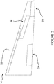
- the wing 14 is configured with a plurality of flight control surfaces 18.
- the wing 14 is a flexible wing, and has a one or more slats 22, a flap 24, a spoiler 26, and an aileron 28.
- the spoiler 26 is a multi-function spoiler.
- the aileron 28 is a wholly-formed aileron.
- the aileron 28 is a split aileron, which is composed of a plurality of portions which may vary in shape and size. The split aileron portions may be rectangular, trapezoidal, square, parallelogram-like, or may take on any other suitable shape.
- the portions of the split aileron are all of the same shape and/or size, and in other embodiments the portions are of different shapes and/or sizes. In some embodiments, the portions of the split aileron are adjacent, and in other embodiments one or more wing structures (not illustrated) of the wing 14 is disposed between the portions of the split aileron.
- the split aileron may be split into two, three, four, or five portions, or may be split into any other suitable number of portions.
- the aircraft 10 may use a fly-by-wire (FBW) control system 30 which has a FBW controller 32 which controls the operation of the flight control surfaces 18, including the spoiler 26 and the aileron 28.
- FBW control system 30 may include the operator controls which provide operator commands, in the form of electrical signals, to the FBW controller 32.
- the FBW controller 32 may combine the operator commands with other aircraft data to produce flight control signals. Instead of mechanical linkages and their attendant displacement/translation, the commands are transmitted across wires to electrically control the movement of actuator/motors that move the flight control surfaces 18.
- the FBW control system 30 includes redundant components (not illustrated) so that if one component of the FBW control system 30 fails, the aircraft 10 can still be safely controlled.
- redundancy is provided on an axis-by-axis basis.
- the FBW control system 30 has separate systems that control the movement of the aircraft 10 in each of the roll, pitch and yaw axes.
- the split aileron 28 is controlled by a single actuator/motor which moves each of the portions of the split aileron in accordance with aileron control signals sent by the FBW controller 32.
- each of the portions of the split aileron is provided with a separate actuator/motor.
- one or more portions of the split aileron share an actuator/motor, and one or more other portions of the split aileron are provided with separate actuators/motors, as appropriate.
- the FBW controller 32 is configured for providing aileron control signals to the actuators/motors which move each of the portions of the split aileron.
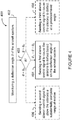
- the FBW control system 30 is configured for implementing a method 400 for managing gust loading in an aircraft, such as the aircraft 10. While the following paragraphs discuss the various flight control surfaces 18 in the singular, it should be noted that in certain embodiments the steps described herein apply to a plurality of flight control surfaces 18 present on both wings 14.
- a deflection angle ⁇ of the spoiler 26 is monitored.
- the spoiler deflection angle ⁇ may be monitored by any suitable means, for example by way of a sensor.
- the spoiler deflection angle ⁇ is continuously monitored, for example by the FBW controller 32, or by other suitable components of the FBW system 30, and may be logged in a memory or other data storage device.
- the spoiler deflection angle ⁇ can be extracted from an operator command received from the operator controls, for example an operator command for causing a deflection of the spoiler 26.
- the spoiler deflection angle ⁇ may be represented within the FBW control system 30 via any suitable means and using any suitable units.
- the spoiler deflection angle ⁇ is stored as a floating point variable indicative of a number of radians of deflection from an origin point.
- the spoiler deflection angle ⁇ is stored as a floating point variable indicative of a number of degrees of deflection relative to a "neutral" reference point, such as a horizontal ground or sea level.
- Other methods of representing and/or storing the spoiler deflection angle ⁇ are also considered.
- the spoiler deflection angle ⁇ is compared against a pair of threshold angles, as illustrated by decision box 403. If the spoiler deflection angle ⁇ is greater than the first threshold angle ⁇ t1 but less than the second threshold angle ⁇ t2 (with ⁇ t2 being greater than ⁇ t1 ), the method 400 moves to step 404. Optionally, decision box 403 can lead to two other steps. If the spoiler deflection angle ⁇ is less than a first threshold angle ⁇ t1 , the method 400 moves to step 406. If the spoiler deflection angle ⁇ is greater than the second threshold angle ⁇ 12 , the method 400 moves to step 408.
- the method 400 only moves to step 408 if the spoiler deflection angle ⁇ is greater than the second threshold angle ⁇ t2 but less than a third threshold angle ⁇ t3 (with ⁇ 13 being greater than ⁇ t2 )
- decision box 403 leads to fourth option (not illustrated) if the spoiler deflection angle ⁇ is above the third threshold angle ⁇ t3 .
- the first, second, and optionally third threshold angles ⁇ t1 , ⁇ t2, ⁇ t3 may be defined as based on any suitable characteristic of the aircraft 10.
- the threshold angles vary with the flexibility of the wings 14, the length and/or shape of the wings 14, the location of the wings 14 on the fuselage 11, and the like.
- the threshold angles may also vary with the size, shape, and location of the spoilers 26 and the ailerons 28.
- the range of motion i.e. the total range of deflection angles, afforded to the spoilers 26 and/or the ailerons 28 may determine at least in part the value of the threshold angles.
- the threshold angles may vary dynamically, for example based on ambient temperature or other environmental factors, on an age or wear level of the aircraft 10 and/or the wing 14, on an operational status of the aircraft 10 and/or of the FBW system 30, and the like.
- the first threshold angle ⁇ t1 is set at 5° and the second threshold angle ⁇ t2 is set at 15°.
- the method 400 moves to step 404, and a first aileron control signal is sent.
- the first aileron control signal may be sent to the aileron 28, or to a controller thereof (not illustrated).
- the first aileron control signal causes the aileron 28 to deflect based on the spoiler deflection angle ⁇ .
- the amount by which the aileron 28 is deflected will vary depending on the value of the spoiler deflection angle ⁇ .
- the FBW controller 32 receives a command to deploy the spoiler 26 to a certain angle.
- the command may be for causing the spoiler 26 to be deployed to a predetermined angle, to a position relative to the total possible deployment (e.g. 50% deployed), or to be fully deployed.
- the first aileron control signal is sent.
- the first aileron control signal instructs the aileron 28 and/or a controller thereof to cause the aileron 28 to deflect.
- further first aileron control signals may be sent to the aileron 28 or the controller thereof to cause the aileron 28 to deflect based on the spoiler deflection angle ⁇ .
- the first aileron control signal may also cause the aileron 28 to vary an angle of deflection of the aileron 28 in a fashion commensurate with the variation of the spoiler deflection angle ⁇ .
- the aileron deflection angle may follow a trajectory based on the variation of the spoiler deflection angle ⁇ .
- the aileron deflection angle follows a trajectory based on an interpolation between two points, for example the aileron deflection angle when the spoiler deflection angle ⁇ is equal to the first threshold angle ⁇ t 1 and a predetermined aileron deflection angle, which may be a maximal deflection angle used for managing gust loading.
- the interpolation may be a linear interpolation, or may follow some non-linear function or equation.
- the first aileron control signal may vary depending on the direction of deployment of the spoiler 26, the first aileron control signal may vary. Put differently, the first aileron control signal sent to the aileron 28 and/or the aileron controller when the spoiler 26 is deployed to extend away from the wing 14 may be different from the first aileron control signal sent to the aileron 28 and/or the aileron controller when the spoiler 26 is deployed to retract toward the wing 14. In some such embodiments, the aileron deflection angle follows a hysteresis curve based on the spoiler deflection angle ⁇ . For example, a first portion of the hysteresis curve is followed when the spoiler 26 is extending away from the wing 14, and a second portion of the hysteresis curve is followed when the spoiler 26 is retracting toward the wing 14.
- the first aileron control signal causes the aileron 28 to deflect along a trajectory based on the rate of change of the spoiler deflection angle ⁇ . For example, when the spoiler deflection angle ⁇ varies slowly, the trajectory along which the aileron 28 is deflected approaches the aforementioned predetermined aileron deflection angle less quickly than when the spoiler deflection angle ⁇ varies quickly.
- the first aileron control signal, and the trajectory along which the aileron 28 is deflected may still vary in other ways.
- the aileron 28 may deflect toward the predetermined aileron deflection angle, or to some other value, until the spoiler deflection angle ⁇ reaches the second threshold angle ⁇ t2 .
- the method 400 moves to step 406, and a second aileron control signal is sent.
- the second aileron control signal may be sent to the aileron 28, or to the aileron controller.
- the second aileron control signal allows the aileron 28 a substantially complete range of motion: no deflection is forced upon the aileron 28, and other aileron control signals beyond the first, second, and third aileron control signals discussed herein may cause the aileron 28 to deflect or downward as per one or more commands.
- the second aileron control signal may remove any restrictions which had previously been placed on the deflection of the aileron 28, for example because the spoiler deflection angle ⁇ had previously been above the first threshold angle ⁇ t1 .
- a third aileron control signal is sent.
- the third aileron control may be sent in similar fashion to the first and second aileron control signals.
- the third aileron control signal causes the aileron 28 to deflect to the aforementioned predetermined aileron deflection angle.
- the predetermined aileron deflection angle may be any suitable angle, for example 1 °, 2°, 2.5°, 3°, or any other suitable value.
- the aileron 28 may be maintained at the predetermined aileron deflection angle as long as the spoiler deflection angle is greater than the second angle threshold ⁇ t2 (and optionally, below the third angle threshold ⁇ t3 ).
- the first, second, and third aileron control signals are generated by the FBW controller 32.
- the aileron control signals may be generated in any suitable way, and may be in any suitable format.
- the aileron control signals are digital, and in other embodiments, the aileron control signals are analog. If the spoiler deflection angle ⁇ is determined to be exactly at one of the threshold angles ⁇ t1 , ⁇ t2 , and optionally ⁇ t3 , the decision box 403 may proceed with the lower option or with the higher option. Alternatively, the decision box 403 may rely on other factors to choose which of steps 404, 406, 408 to implement if the spoiler deflection angle ⁇ is determined to be exactly at one of the threshold angles.
- the portions may be divided into groups, and different aileron control signals may be sent to the different groups.
- the first aileron control signals can cause a first group of portions to be deflected upward at a first aileron deflection angle, and to follow a first deflection trajectory, and can cause a second group of portions to be deflected upward at a second aileron deflection angle, and to follow a second deflection trajectory.
- the third aileron control signals can cause the first group of portions to be deflected at a first predetermined aileron deflection angle, and can cause the second group of portions to be deflected at a second predetermined aileron deflection angle.
- the portions may be divided into three or more groups and similar deflection patterns may apply.
- the effective surface area of the wing 14 can be varied to passively manage gust loading and to adjust level flight load distribution. More specifically, many jurisdictions have regulations which require that gust loading be computed for both deployed and retracted spoilers 26. When the spoilers 26 deploy, the amount of lift in the area of the wing 14 where the aileron 28 is located is increased to recover level flight. This is because the spoilers 26 cause lift loss, and by adjusting the ailerons 28 the aircraft 10 can recover the lift. The outer wing lift is then reduced again by gust loading alleviation by putting the ailerons up such that the total load remains within the given structural strength.
- the aileron deflection angle as a function of the spoiler deflection angle ⁇ can be represented in graphical form by line 500.
- the first threshold angle ⁇ t1 which is set at 5°
- no aileron deflection is forced upon the aileron 28.
- the second threshold angle ⁇ t2 which is set at 15°
- the aileron deflection can follow a linear path.
- the aileron deflection can be set at the predetermined aileron deflection angle, which is set at 2.5°.
- the ailerons 28 of the wings 14 of the aircraft 10 are provided with different aileron control signals depending on the wing 14 on which they are located.
- FIG. 6A-B an example control scheme for aileron deflection are illustrated, showing the aileron deflection angle caused by a given aileron deflection command.
- respective aileron control signals are sent to the ailerons 28 located on the wings 14, such that a port-side wing 14 is provided the control scheme of Figure 6A , and a starboard-side wing 14 is provided the control scheme of Figure 6B .
- Lines 602 and 612 represent the aileron deflection angle when the spoiler 26 is deflected at an angle equal or below the first threshold angle ⁇ t1 , illustrating the full range of motion of the aileron 28.
- Lines 604 and 614 represent the aileron deflection angle when the spoiler 26 is deflected at an angle between the first threshold angle ⁇ t1 and the second threshold angle ⁇ t2 , illustrating the linear interpolation of the aileron deflection angle.
- Lines 606 and 616 represent the aileron deflection angle when the spoiler 26 is deflected at an angle beyond the second threshold angle ⁇ t2 , illustrating the aileron 28 being deflected at the predetermined aileron deflection angle, in this case 2.5°.
- the method 400 may be implemented by a computing device 710, comprising a processing unit 712 and a memory 714 which has stored therein computer-executable instructions 716.
- the processing unit 712 may comprise any suitable devices configured to cause a series of steps to be performed so as to implement the method 400 such that instructions 716, when executed by the computing device 710 or other programmable apparatus, may cause the functions/acts/steps specified in the methods described herein to be executed.
- the processing unit 712 may comprise, for example, any type of general-purpose microprocessor or microcontroller, a digital signal processing (DSP) processor, a central processing unit (CPU), an integrated circuit, a field programmable gate array (FPGA), a reconfigurable processor, other suitably programmed or programmable logic circuits, or any combination thereof.
- DSP digital signal processing
- CPU central processing unit
- FPGA field programmable gate array
- reconfigurable processor other suitably programmed or programmable logic circuits, or any combination thereof.
- the memory 714 may comprise any suitable known or other machine-readable storage medium.
- the memory 714 may comprise non-transitory computer readable storage medium such as, for example, but not limited to, an electronic, magnetic, optical, electromagnetic, infrared, or semiconductor system, apparatus, or device, or any suitable combination of the foregoing.
- the memory 714 may include a suitable combination of any type of computer memory that is located either internally or externally to device such as, for example, random-access memory (RAM), read-only memory (ROM), compact disc read-only memory (CDROM), electro-optical memory, magneto-optical memory, erasable programmable read-only memory (EPROM), and electrically-erasable programmable read-only memory (EEPROM), Ferroelectric RAM (FRAM) or the like.
- Memory may comprise any storage means (e.g., devices) suitable for retrievably storing machine-readable instructions executable by processing unit.
- aileron control system 800 may be included in the FBW controller 32, and includes a spoiler deflection angle evaluation unit 820, an aileron control signal unit 830, and optionally a command processing unit 810.
- the spoiler deflection angle evaluation unit 820 is configured for monitoring the spoiler deflection angle ⁇ of the spoiler 26, in accordance with step 402.
- the spoiler deflection angle evaluation unit 820 may monitor the spoiler deflection angle ⁇ by way of an optional sensor 804, or may extract the spoiler deflection angle ⁇ from a command.
- the command may be received from the operator controls 802 by the command processing unit 810, which may determine whether the command is for causing a change in the spoiler deflection angle ⁇ . If the command is for causing a change in the spoiler deflection angle ⁇ , the command processing unit 10 may pass on the command to the spoiler deflection angle evaluation unit 820, which may the extract the spoiler deflection angle ⁇ from the command.
- the spoiler deflection angle evaluation unit 820 is configured for providing the spoiler deflection angle ⁇ to the aileron control signal unit 830, which then implements the decision box 403, and proceeds to perform step 404 when the spoiler deflection angle ⁇ is between the first threshold angle ⁇ t1 and the second threshold angle ⁇ t2 , to perform step 406 when the spoiler deflection angle ⁇ is below the first threshold angle ⁇ t1 , to perform step 408 when the spoiler deflection angle ⁇ is above the second threshold angle ⁇ t2 .
- the aileron control signal unit 830 is configured to send aileron control signals to the aileron 28 to cause the aileron 28 to behave in one or more of the ways described hereinabove.
- the aileron control signal unit 830 sends the aileron control signals directly to motors/actuators (not illustrated) of the aileron 28. In other embodiments, the aileron control signals are sent to an intermediary unit (not pictured), which translates the aileron control signals sent by the aileron control signal unit 830 into signals to be sent to the aileron 28.
- the methods and systems for managing gust loading in an aircraft may be implemented in a high level procedural or object oriented programming or scripting language, or a combination thereof, to communicate with or assist in the operation of a computer system, for example the computing device 710.
- the methods and systems for managing gust loading in an aircraft described herein may be implemented in assembly or machine language.
- the language may be a compiled or interpreted language.
- Program code for implementing the methods and systems for managing gust loading in an aircraft described herein may be stored on a storage media or a device, for example a ROM, a magnetic disk, an optical disc, a flash drive, or any other suitable storage media or device.
- the program code may be readable by a general or special-purpose programmable computer for configuring and operating the computer when the storage media or device is read by the computer to perform the procedures described herein.
- Embodiments of the methods and systems for managing gust loading in an aircraft described herein may also be considered to be implemented by way of a non-transitory computer-readable storage medium having a computer program stored thereon.
- the computer program may comprise computer-readable instructions which cause a computer, or more specifically the at least one processing unit of the computer, to operate in a specific and predefined manner to perform the functions described herein.
- Computer-executable instructions may be in many forms, including program modules, executed by one or more computers or other devices.
- program modules include routines, programs, objects, components, data structures, etc., that perform particular tasks or implement particular abstract data types.
- functionality of the program modules may be combined or distributed as desired in various embodiments.
Landscapes
- Engineering & Computer Science (AREA)
- Aviation & Aerospace Engineering (AREA)
- Automation & Control Theory (AREA)
- Toys (AREA)
- Traffic Control Systems (AREA)
Claims (14)
- Verfahren zum Handhaben von Belastungen durch Windstöße bei einem Luftfahrzeug (10), dadurch gekennzeichnet, dass es
ein Überwachen eines Störklappenauslenkwinkels (Θ) wenigstens einer Störklappe (26) des Luftfahrzeugs (10), und
falls der Störklappenauslenkwinkel (Θ) oberhalb eines ersten Schwellwerts (Θt1) ist, ein Aussenden wenigstens eines Querruderansteuersignals zum Bewirken, dass sich wenigstens ein Querruder (28) in Abhängigkeit des Störklappenauslenkwinkels (Θ) auslenkt, umfasst. - Verfahren nach Anspruch 1, bei dem, falls der Störklappenauslenkwinkel (Θ) oberhalb des ersten Schwellwerts (Θt1) und unterhalb eines zweiten Schwellwerts (Θt2) ist, der größer als der erste Schwellwert (Θt1) ist, das wenigstens eine Querruderansteuersignal wenigstens ein erstes Querruderansteuersignal umfasst, um zu bewirken, dass wenigstens ein Querruder (28) gemäß einer interpolierten Trajektorie ausgelenkt wird.
- Verfahren nach Anspruch 2, bei dem die interpolierte Trajektorie eine linear interpolierte Trajektorie auf der Grundlage eines Querruderauslenkwinkels des Querruders (28) bei dem ersten Schwellwert (Θt1) und eines vorbestimmten Winkels ist.
- Verfahren nach Anspruch 1, bei dem, falls der Störklappenauslenkwinkel (Θ) oberhalb des zweiten Schwellwerts (Θt2) ist, das wenigstens eine Querruderansteuersignal ein zweites Querruderansteuersignal umfasst, um zu bewirken, dass das wenigstens eine Querruder (28) nach oben zu einem vorbestimmten Winkel ausgelenkt wird.
- Verfahren nach Anspruch 4, bei dem das wenigstens eine zweite Querruderansteuersignal zu dem wenigstens einen Querruder gesendet wird, wenn der Querruderauslenkwinkel (Θ) oberhalb des zweiten Schwellwerts (Θt2) und unterhalb eines dritten Schwellwerts (Θt3) ist, der größer als der zweite Schwellwert (Θt2) ist.
- Verfahren nach Anspruch 4, bei dem, falls der Störklappenauslenkwinkel (Θ) unterhalb des ersten Schwellwerts (Θt1) ist, das wenigstens eine Querruderansteuersignal wenigstens ein drittes Querruderansteuersignal umfasst, um dem wenigstens einem Querruder (28) einen im Wesentlichen vollständigen Bewegungsbereich zu gestatten.
- Verfahren nah einem der Ansprüche 1 bis 6, bei dem das Überwachen des Störklappenauslenkwinkels (Θ) wenigstens einer Störklappe (26) des Luftfahrzeugs (10) ein kontinuierliches Überwachen des Störklappenauslenkwinkels (Θ) aufweist.
- Verfahren nach einem der Ansprüche 1 bis 7, bei dem das wenigstens eine Querruderansteuersignal auf der Grundlage der Einsatzrichtung der Störklappe (26) verschieden ist.
- Verfahren nach Anspruch 8, bei dem das Querruderansteuersignal ein Auslenken des wenigstens einen Querruders (28) entlang einer von zwei Abschnitten einer Hysteresetrajektorie auf der Grundlage der Einsatzrichtung der Störklappe (26) bewirkt.
- Verfahren nach einem der Ansprüche 1 bis 7, bei dem das Querruderansteuersignal ein Auslenken des wenigstens einen Querruders (28) entlang einer Trajektorie auf der Grundlage einer Änderungsrate des Störklappenauslenkwinkels (Θ) bewirkt.
- Verfahren nach einem der Ansprüche 1 bis 10, bei dem ein Überwachen der Störklappenauslenkwinkels (Θ) den Empfang eines Steuerbefehls und das Extrahieren des Störklappenauslenkwinkels (Θ) daraus umfasst.
- Verfahren nach einem der Ansprüche 1 bis 11, bei dem
das Aussenden des wenigstens einen Querruderansteuersignals das Aussenden von einem zugehörigen Querruderansteuersignal zu einer Anzahl von Abschnitten wenigstens eines geteilten Querruders (28) umfasst und
ein Verursachen einer Auslenkung des wenigstens einen Querruders (28) auf der Grundlage des Störklappenauslenkwinkels (Θ) ein Verursachen jedes Abschnitts des wenigstens einen geteilten Querruders (28) zum Auslenken auf der Grundlage des Störklappenauslenkwinkels (Θ) umfasst. - Verfahren nach Anspruch 12, bei dem
die Anzahl von Abschnitten des wenigstens einen geteilten Querruders (28) wenigstens eine erste Gruppe von Abschnitten sowie eine zweite Gruppe von Abschnitten umfasst und
ein Verursachen des Auslenkens jedes Abschnittes des wenigstens einen geteilten Querruders (28) auf der Grundlage des Störklappenauslenkwinkels (Θ)ein Verursachen der Auslenkung einer ersten Gruppe von Abschnitten durch einen ersten Querruderauslenkwinkel, undein Verursachen einer Auslenkung der zweiten Gruppe von Abschnitten durch einen zweiten Querruderauslenkwinkelumfasst. - System zum Handhaben von Belastungen durch Windstöße bei einem Luftfahrzeug (10), wobei das System dadurch gekennzeichnet ist, dass es
eine Verarbeitungseinheit, und
einen nichtflüchtigen Speicher umfasst, der datenaustauschmäßig mit der Verarbeitungseinheit verbunden ist und computerlesbare Programmanweisungen aufweist, die durch die Verarbeitungseinheit ausführbar sind, um die Schritte des Verfahrens zum Handhaben von Belastungen durch Windstöße bei einem Luftfahrzeug (10) gemäß einem der Ansprüche 1 bis 13 auszuführen.
Applications Claiming Priority (2)
| Application Number | Priority Date | Filing Date | Title |
|---|---|---|---|
| US201662352850P | 2016-06-21 | 2016-06-21 | |
| PCT/IB2017/053603 WO2017221123A1 (en) | 2016-06-21 | 2017-06-16 | Gust loading management |
Publications (2)
| Publication Number | Publication Date |
|---|---|
| EP3472045A1 EP3472045A1 (de) | 2019-04-24 |
| EP3472045B1 true EP3472045B1 (de) | 2021-01-13 |
Family
ID=59270067
Family Applications (1)
| Application Number | Title | Priority Date | Filing Date |
|---|---|---|---|
| EP17734835.6A Active EP3472045B1 (de) | 2016-06-21 | 2017-06-16 | Böenlastverwaltung |
Country Status (5)
| Country | Link |
|---|---|
| US (1) | US10875630B2 (de) |
| EP (1) | EP3472045B1 (de) |
| CN (1) | CN109715492B (de) |
| CA (1) | CA3028953A1 (de) |
| WO (1) | WO2017221123A1 (de) |
Families Citing this family (5)
| Publication number | Priority date | Publication date | Assignee | Title |
|---|---|---|---|---|
| WO2018002799A1 (en) * | 2016-06-30 | 2018-01-04 | Bombardier Inc. | Split-aileron control |
| CN112678167B (zh) * | 2020-12-28 | 2024-01-02 | 中国航空工业集团公司沈阳飞机设计研究所 | 一种尾坐飞机垂直起降控制方法 |
| CN114954910B (zh) * | 2021-02-18 | 2024-06-11 | 海鹰航空通用装备有限责任公司 | 一种可调后掠角的副翼操纵机构及具有其的无人机 |
| EP4079632B1 (de) | 2021-04-21 | 2025-08-20 | Goodrich Actuation Systems Limited | Vorderkanten-hochauftriebsarchitektur |
| CN114560073B (zh) * | 2021-12-30 | 2024-01-30 | 中国航空工业集团公司西安飞机设计研究所 | 一种螺旋桨飞机滑流预感知方向舵偏转控制方法及其系统 |
Family Cites Families (11)
| Publication number | Priority date | Publication date | Assignee | Title |
|---|---|---|---|---|
| US4472780A (en) * | 1981-09-28 | 1984-09-18 | The Boeing Company | Fly-by-wire lateral control system |
| US5493497A (en) * | 1992-06-03 | 1996-02-20 | The Boeing Company | Multiaxis redundant fly-by-wire primary flight control system |
| ATE385948T1 (de) | 2004-06-16 | 2008-03-15 | Airbus Gmbh | Vorrichtung und verfahren zur bedämpfung mindestens einer starrkörpereigenform und/oder mindestens einer elastischen eigenbewegungsform eines luftfahrzeuges |
| FR2901537B1 (fr) * | 2006-05-29 | 2008-07-04 | Airbus France Sas | Procede et dispositif de pilotage d'un aeronef optimisant la commande des ailerons en configuration hypersustentee |
| US8024079B2 (en) * | 2008-05-20 | 2011-09-20 | The Boeing Company | Wing-body load alleviation for aircraft |
| DE102009013758A1 (de) * | 2009-03-17 | 2010-09-23 | Airbus Deutschland Gmbh | Flugzeug mit einer Vorrichtung zur Beeinflussung der Richtungsstabilität des Flugzeugs sowie Verfahren zur Beeinflussung der Richtungsstabilität des Flugzeugs |
| DE102009060327A1 (de) * | 2009-12-23 | 2011-06-30 | Airbus Operations GmbH, 21129 | Flugzeug mit einer Steuerungsvorrichtung |
| EP2615026B1 (de) * | 2011-06-10 | 2018-04-04 | Airbus Defence and Space GmbH | Verfahren und Vorrichtung zur Minimierung der dynamischen Strukturbelastungen eines Flugzeugs |
| ES2543633T3 (es) * | 2011-07-28 | 2015-08-20 | Airbus Defence and Space GmbH | Método y aparato para minimizar las cargas estructurales dinámicas de un avión |
| EP3066424A1 (de) | 2013-12-11 | 2016-09-14 | Moog Inc. | Faseroptisches abtast- und steuerungssystem |
| US10183738B2 (en) | 2014-04-08 | 2019-01-22 | Marc Arnold | Flight control augmentation system and method for high aspect ratio aircraft including motorglider aircraft, optionally piloted vehicles (OPVs) and unpiloted air vehicles (UAVs) |
-
2017
- 2017-06-16 US US16/311,832 patent/US10875630B2/en active Active
- 2017-06-16 EP EP17734835.6A patent/EP3472045B1/de active Active
- 2017-06-16 CA CA3028953A patent/CA3028953A1/en active Pending
- 2017-06-16 WO PCT/IB2017/053603 patent/WO2017221123A1/en not_active Ceased
- 2017-06-16 CN CN201780038907.9A patent/CN109715492B/zh active Active
Non-Patent Citations (1)
| Title |
|---|
| None * |
Also Published As
| Publication number | Publication date |
|---|---|
| US10875630B2 (en) | 2020-12-29 |
| CA3028953A1 (en) | 2017-12-28 |
| CN109715492A (zh) | 2019-05-03 |
| EP3472045A1 (de) | 2019-04-24 |
| WO2017221123A1 (en) | 2017-12-28 |
| US20190202544A1 (en) | 2019-07-04 |
| CN109715492B (zh) | 2022-07-29 |
Similar Documents
| Publication | Publication Date | Title |
|---|---|---|
| US10875630B2 (en) | Gust loading management | |
| US10788827B2 (en) | Aircraft wing structure and control system | |
| JP6826068B2 (ja) | 流れ制御システム、流れ制御方法及び航空機 | |
| EP2944566B1 (de) | System und verfahren zur optimierung von belastungen des horizontalen hecks | |
| CN104303124B (zh) | 用于配置运载工具的直接升力控制系统的系统和方法 | |
| US8998132B2 (en) | Aerodynamic wing load distribution control | |
| CN114035433A (zh) | 用于增强性能的陡直爬升保护系统 | |
| JP2009538779A (ja) | 高揚力形態において補助翼の制御を最適化する航空機の操縦方法および装置 | |
| EP3141976B1 (de) | Rolllagenabhängige rollratengrenze | |
| US11565792B2 (en) | Methods and systems for deploying adjacent trailing edge flaps | |
| EP3478576B1 (de) | Ansteuerung eines geteilten querruders | |
| CA3028950A1 (en) | Control laws for pedal-to-roll coupling | |
| US20220097827A1 (en) | Aircraft pitch control system with electronically geared elevator | |
| EP3744641A1 (de) | System und verfahren zur bestimmung einer schräglage |
Legal Events
| Date | Code | Title | Description |
|---|---|---|---|
| STAA | Information on the status of an ep patent application or granted ep patent |
Free format text: STATUS: UNKNOWN |
|
| STAA | Information on the status of an ep patent application or granted ep patent |
Free format text: STATUS: THE INTERNATIONAL PUBLICATION HAS BEEN MADE |
|
| PUAI | Public reference made under article 153(3) epc to a published international application that has entered the european phase |
Free format text: ORIGINAL CODE: 0009012 |
|
| STAA | Information on the status of an ep patent application or granted ep patent |
Free format text: STATUS: REQUEST FOR EXAMINATION WAS MADE |
|
| 17P | Request for examination filed |
Effective date: 20190121 |
|
| AK | Designated contracting states |
Kind code of ref document: A1 Designated state(s): AL AT BE BG CH CY CZ DE DK EE ES FI FR GB GR HR HU IE IS IT LI LT LU LV MC MK MT NL NO PL PT RO RS SE SI SK SM TR |
|
| AX | Request for extension of the european patent |
Extension state: BA ME |
|
| DAV | Request for validation of the european patent (deleted) | ||
| DAX | Request for extension of the european patent (deleted) | ||
| GRAP | Despatch of communication of intention to grant a patent |
Free format text: ORIGINAL CODE: EPIDOSNIGR1 |
|
| STAA | Information on the status of an ep patent application or granted ep patent |
Free format text: STATUS: GRANT OF PATENT IS INTENDED |
|
| INTG | Intention to grant announced |
Effective date: 20200424 |
|
| GRAJ | Information related to disapproval of communication of intention to grant by the applicant or resumption of examination proceedings by the epo deleted |
Free format text: ORIGINAL CODE: EPIDOSDIGR1 |
|
| STAA | Information on the status of an ep patent application or granted ep patent |
Free format text: STATUS: REQUEST FOR EXAMINATION WAS MADE |
|
| GRAP | Despatch of communication of intention to grant a patent |
Free format text: ORIGINAL CODE: EPIDOSNIGR1 |
|
| STAA | Information on the status of an ep patent application or granted ep patent |
Free format text: STATUS: GRANT OF PATENT IS INTENDED |
|
| INTC | Intention to grant announced (deleted) | ||
| INTG | Intention to grant announced |
Effective date: 20200812 |
|
| RAP1 | Party data changed (applicant data changed or rights of an application transferred) |
Owner name: AIRBUS CANADA LIMITED PARTNERSHIP |
|
| GRAS | Grant fee paid |
Free format text: ORIGINAL CODE: EPIDOSNIGR3 |
|
| GRAA | (expected) grant |
Free format text: ORIGINAL CODE: 0009210 |
|
| STAA | Information on the status of an ep patent application or granted ep patent |
Free format text: STATUS: THE PATENT HAS BEEN GRANTED |
|
| AK | Designated contracting states |
Kind code of ref document: B1 Designated state(s): AL AT BE BG CH CY CZ DE DK EE ES FI FR GB GR HR HU IE IS IT LI LT LU LV MC MK MT NL NO PL PT RO RS SE SI SK SM TR |
|
| REG | Reference to a national code |
Ref country code: GB Ref legal event code: FG4D |
|
| REG | Reference to a national code |
Ref country code: CH Ref legal event code: EP |
|
| REG | Reference to a national code |
Ref country code: IE Ref legal event code: FG4D |
|
| REG | Reference to a national code |
Ref country code: DE Ref legal event code: R096 Ref document number: 602017031372 Country of ref document: DE |
|
| REG | Reference to a national code |
Ref country code: AT Ref legal event code: REF Ref document number: 1354377 Country of ref document: AT Kind code of ref document: T Effective date: 20210215 |
|
| REG | Reference to a national code |
Ref country code: AT Ref legal event code: MK05 Ref document number: 1354377 Country of ref document: AT Kind code of ref document: T Effective date: 20210113 |
|
| REG | Reference to a national code |
Ref country code: NL Ref legal event code: MP Effective date: 20210113 |
|
| REG | Reference to a national code |
Ref country code: LT Ref legal event code: MG9D |
|
| PG25 | Lapsed in a contracting state [announced via postgrant information from national office to epo] |
Ref country code: LT Free format text: LAPSE BECAUSE OF FAILURE TO SUBMIT A TRANSLATION OF THE DESCRIPTION OR TO PAY THE FEE WITHIN THE PRESCRIBED TIME-LIMIT Effective date: 20210113 Ref country code: BG Free format text: LAPSE BECAUSE OF FAILURE TO SUBMIT A TRANSLATION OF THE DESCRIPTION OR TO PAY THE FEE WITHIN THE PRESCRIBED TIME-LIMIT Effective date: 20210413 Ref country code: HR Free format text: LAPSE BECAUSE OF FAILURE TO SUBMIT A TRANSLATION OF THE DESCRIPTION OR TO PAY THE FEE WITHIN THE PRESCRIBED TIME-LIMIT Effective date: 20210113 Ref country code: FI Free format text: LAPSE BECAUSE OF FAILURE TO SUBMIT A TRANSLATION OF THE DESCRIPTION OR TO PAY THE FEE WITHIN THE PRESCRIBED TIME-LIMIT Effective date: 20210113 Ref country code: GR Free format text: LAPSE BECAUSE OF FAILURE TO SUBMIT A TRANSLATION OF THE DESCRIPTION OR TO PAY THE FEE WITHIN THE PRESCRIBED TIME-LIMIT Effective date: 20210414 Ref country code: PT Free format text: LAPSE BECAUSE OF FAILURE TO SUBMIT A TRANSLATION OF THE DESCRIPTION OR TO PAY THE FEE WITHIN THE PRESCRIBED TIME-LIMIT Effective date: 20210513 Ref country code: NO Free format text: LAPSE BECAUSE OF FAILURE TO SUBMIT A TRANSLATION OF THE DESCRIPTION OR TO PAY THE FEE WITHIN THE PRESCRIBED TIME-LIMIT Effective date: 20210413 |
|
| PG25 | Lapsed in a contracting state [announced via postgrant information from national office to epo] |
Ref country code: AT Free format text: LAPSE BECAUSE OF FAILURE TO SUBMIT A TRANSLATION OF THE DESCRIPTION OR TO PAY THE FEE WITHIN THE PRESCRIBED TIME-LIMIT Effective date: 20210113 Ref country code: LV Free format text: LAPSE BECAUSE OF FAILURE TO SUBMIT A TRANSLATION OF THE DESCRIPTION OR TO PAY THE FEE WITHIN THE PRESCRIBED TIME-LIMIT Effective date: 20210113 Ref country code: PL Free format text: LAPSE BECAUSE OF FAILURE TO SUBMIT A TRANSLATION OF THE DESCRIPTION OR TO PAY THE FEE WITHIN THE PRESCRIBED TIME-LIMIT Effective date: 20210113 Ref country code: RS Free format text: LAPSE BECAUSE OF FAILURE TO SUBMIT A TRANSLATION OF THE DESCRIPTION OR TO PAY THE FEE WITHIN THE PRESCRIBED TIME-LIMIT Effective date: 20210113 Ref country code: SE Free format text: LAPSE BECAUSE OF FAILURE TO SUBMIT A TRANSLATION OF THE DESCRIPTION OR TO PAY THE FEE WITHIN THE PRESCRIBED TIME-LIMIT Effective date: 20210113 |
|
| PG25 | Lapsed in a contracting state [announced via postgrant information from national office to epo] |
Ref country code: IS Free format text: LAPSE BECAUSE OF FAILURE TO SUBMIT A TRANSLATION OF THE DESCRIPTION OR TO PAY THE FEE WITHIN THE PRESCRIBED TIME-LIMIT Effective date: 20210513 |
|
| REG | Reference to a national code |
Ref country code: DE Ref legal event code: R097 Ref document number: 602017031372 Country of ref document: DE |
|
| PG25 | Lapsed in a contracting state [announced via postgrant information from national office to epo] |
Ref country code: CZ Free format text: LAPSE BECAUSE OF FAILURE TO SUBMIT A TRANSLATION OF THE DESCRIPTION OR TO PAY THE FEE WITHIN THE PRESCRIBED TIME-LIMIT Effective date: 20210113 Ref country code: EE Free format text: LAPSE BECAUSE OF FAILURE TO SUBMIT A TRANSLATION OF THE DESCRIPTION OR TO PAY THE FEE WITHIN THE PRESCRIBED TIME-LIMIT Effective date: 20210113 Ref country code: SM Free format text: LAPSE BECAUSE OF FAILURE TO SUBMIT A TRANSLATION OF THE DESCRIPTION OR TO PAY THE FEE WITHIN THE PRESCRIBED TIME-LIMIT Effective date: 20210113 |
|
| PLBE | No opposition filed within time limit |
Free format text: ORIGINAL CODE: 0009261 |
|
| STAA | Information on the status of an ep patent application or granted ep patent |
Free format text: STATUS: NO OPPOSITION FILED WITHIN TIME LIMIT |
|
| PG25 | Lapsed in a contracting state [announced via postgrant information from national office to epo] |
Ref country code: RO Free format text: LAPSE BECAUSE OF FAILURE TO SUBMIT A TRANSLATION OF THE DESCRIPTION OR TO PAY THE FEE WITHIN THE PRESCRIBED TIME-LIMIT Effective date: 20210113 Ref country code: DK Free format text: LAPSE BECAUSE OF FAILURE TO SUBMIT A TRANSLATION OF THE DESCRIPTION OR TO PAY THE FEE WITHIN THE PRESCRIBED TIME-LIMIT Effective date: 20210113 Ref country code: SK Free format text: LAPSE BECAUSE OF FAILURE TO SUBMIT A TRANSLATION OF THE DESCRIPTION OR TO PAY THE FEE WITHIN THE PRESCRIBED TIME-LIMIT Effective date: 20210113 |
|
| 26N | No opposition filed |
Effective date: 20211014 |
|
| PG25 | Lapsed in a contracting state [announced via postgrant information from national office to epo] |
Ref country code: ES Free format text: LAPSE BECAUSE OF FAILURE TO SUBMIT A TRANSLATION OF THE DESCRIPTION OR TO PAY THE FEE WITHIN THE PRESCRIBED TIME-LIMIT Effective date: 20210113 Ref country code: MC Free format text: LAPSE BECAUSE OF FAILURE TO SUBMIT A TRANSLATION OF THE DESCRIPTION OR TO PAY THE FEE WITHIN THE PRESCRIBED TIME-LIMIT Effective date: 20210113 Ref country code: AL Free format text: LAPSE BECAUSE OF FAILURE TO SUBMIT A TRANSLATION OF THE DESCRIPTION OR TO PAY THE FEE WITHIN THE PRESCRIBED TIME-LIMIT Effective date: 20210113 |
|
| REG | Reference to a national code |
Ref country code: CH Ref legal event code: PL |
|
| PG25 | Lapsed in a contracting state [announced via postgrant information from national office to epo] |
Ref country code: SI Free format text: LAPSE BECAUSE OF FAILURE TO SUBMIT A TRANSLATION OF THE DESCRIPTION OR TO PAY THE FEE WITHIN THE PRESCRIBED TIME-LIMIT Effective date: 20210113 |
|
| REG | Reference to a national code |
Ref country code: BE Ref legal event code: MM Effective date: 20210630 |
|
| PG25 | Lapsed in a contracting state [announced via postgrant information from national office to epo] |
Ref country code: LU Free format text: LAPSE BECAUSE OF NON-PAYMENT OF DUE FEES Effective date: 20210616 |
|
| PG25 | Lapsed in a contracting state [announced via postgrant information from national office to epo] |
Ref country code: LI Free format text: LAPSE BECAUSE OF NON-PAYMENT OF DUE FEES Effective date: 20210630 Ref country code: IT Free format text: LAPSE BECAUSE OF FAILURE TO SUBMIT A TRANSLATION OF THE DESCRIPTION OR TO PAY THE FEE WITHIN THE PRESCRIBED TIME-LIMIT Effective date: 20210113 Ref country code: IE Free format text: LAPSE BECAUSE OF NON-PAYMENT OF DUE FEES Effective date: 20210616 Ref country code: CH Free format text: LAPSE BECAUSE OF NON-PAYMENT OF DUE FEES Effective date: 20210630 |
|
| PG25 | Lapsed in a contracting state [announced via postgrant information from national office to epo] |
Ref country code: IS Free format text: LAPSE BECAUSE OF FAILURE TO SUBMIT A TRANSLATION OF THE DESCRIPTION OR TO PAY THE FEE WITHIN THE PRESCRIBED TIME-LIMIT Effective date: 20210513 |
|
| PG25 | Lapsed in a contracting state [announced via postgrant information from national office to epo] |
Ref country code: BE Free format text: LAPSE BECAUSE OF NON-PAYMENT OF DUE FEES Effective date: 20210630 |
|
| PG25 | Lapsed in a contracting state [announced via postgrant information from national office to epo] |
Ref country code: NL Free format text: LAPSE BECAUSE OF NON-PAYMENT OF DUE FEES Effective date: 20210113 Ref country code: CY Free format text: LAPSE BECAUSE OF FAILURE TO SUBMIT A TRANSLATION OF THE DESCRIPTION OR TO PAY THE FEE WITHIN THE PRESCRIBED TIME-LIMIT Effective date: 20210113 |
|
| PG25 | Lapsed in a contracting state [announced via postgrant information from national office to epo] |
Ref country code: HU Free format text: LAPSE BECAUSE OF FAILURE TO SUBMIT A TRANSLATION OF THE DESCRIPTION OR TO PAY THE FEE WITHIN THE PRESCRIBED TIME-LIMIT; INVALID AB INITIO Effective date: 20170616 |
|
| PG25 | Lapsed in a contracting state [announced via postgrant information from national office to epo] |
Ref country code: MK Free format text: LAPSE BECAUSE OF FAILURE TO SUBMIT A TRANSLATION OF THE DESCRIPTION OR TO PAY THE FEE WITHIN THE PRESCRIBED TIME-LIMIT Effective date: 20210113 |
|
| PG25 | Lapsed in a contracting state [announced via postgrant information from national office to epo] |
Ref country code: TR Free format text: LAPSE BECAUSE OF FAILURE TO SUBMIT A TRANSLATION OF THE DESCRIPTION OR TO PAY THE FEE WITHIN THE PRESCRIBED TIME-LIMIT Effective date: 20210113 |
|
| PG25 | Lapsed in a contracting state [announced via postgrant information from national office to epo] |
Ref country code: MT Free format text: LAPSE BECAUSE OF FAILURE TO SUBMIT A TRANSLATION OF THE DESCRIPTION OR TO PAY THE FEE WITHIN THE PRESCRIBED TIME-LIMIT Effective date: 20210113 |
|
| PGFP | Annual fee paid to national office [announced via postgrant information from national office to epo] |
Ref country code: DE Payment date: 20250618 Year of fee payment: 9 |
|
| PGFP | Annual fee paid to national office [announced via postgrant information from national office to epo] |
Ref country code: GB Payment date: 20250618 Year of fee payment: 9 |
|
| PGFP | Annual fee paid to national office [announced via postgrant information from national office to epo] |
Ref country code: FR Payment date: 20250625 Year of fee payment: 9 |