EP3471501A1 - Wireless communication system - Google Patents
Wireless communication system Download PDFInfo
- Publication number
- EP3471501A1 EP3471501A1 EP17810303.2A EP17810303A EP3471501A1 EP 3471501 A1 EP3471501 A1 EP 3471501A1 EP 17810303 A EP17810303 A EP 17810303A EP 3471501 A1 EP3471501 A1 EP 3471501A1
- Authority
- EP
- European Patent Office
- Prior art keywords
- master device
- slave devices
- slave
- wireless communication
- signal
- Prior art date
- Legal status (The legal status is an assumption and is not a legal conclusion. Google has not performed a legal analysis and makes no representation as to the accuracy of the status listed.)
- Granted
Links
Images




Classifications
-
- H—ELECTRICITY
- H04—ELECTRIC COMMUNICATION TECHNIQUE
- H04W—WIRELESS COMMUNICATION NETWORKS
- H04W8/00—Network data management
- H04W8/005—Discovery of network devices, e.g. terminals
-
- H—ELECTRICITY
- H04—ELECTRIC COMMUNICATION TECHNIQUE
- H04W—WIRELESS COMMUNICATION NETWORKS
- H04W76/00—Connection management
- H04W76/10—Connection setup
-
- H—ELECTRICITY
- H04—ELECTRIC COMMUNICATION TECHNIQUE
- H04W—WIRELESS COMMUNICATION NETWORKS
- H04W52/00—Power management, e.g. Transmission Power Control [TPC] or power classes
- H04W52/02—Power saving arrangements
-
- H—ELECTRICITY
- H04—ELECTRIC COMMUNICATION TECHNIQUE
- H04W—WIRELESS COMMUNICATION NETWORKS
- H04W84/00—Network topologies
- H04W84/18—Self-organising networks, e.g. ad-hoc networks or sensor networks
-
- Y—GENERAL TAGGING OF NEW TECHNOLOGICAL DEVELOPMENTS; GENERAL TAGGING OF CROSS-SECTIONAL TECHNOLOGIES SPANNING OVER SEVERAL SECTIONS OF THE IPC; TECHNICAL SUBJECTS COVERED BY FORMER USPC CROSS-REFERENCE ART COLLECTIONS [XRACs] AND DIGESTS
- Y02—TECHNOLOGIES OR APPLICATIONS FOR MITIGATION OR ADAPTATION AGAINST CLIMATE CHANGE
- Y02D—CLIMATE CHANGE MITIGATION TECHNOLOGIES IN INFORMATION AND COMMUNICATION TECHNOLOGIES [ICT], I.E. INFORMATION AND COMMUNICATION TECHNOLOGIES AIMING AT THE REDUCTION OF THEIR OWN ENERGY USE
- Y02D30/00—Reducing energy consumption in communication networks
- Y02D30/70—Reducing energy consumption in communication networks in wireless communication networks
Definitions
- the present invention relates to a wireless communication system performing wireless communication between a master device and slave devices.
- Patent Document 1 disclosed as follows: In a wireless communication performed between a vehicle and a mobile device, the vehicle periodically receives two channels 1 and 2. When it is determined that noise exists in the channel 1, the channel 2 is used on a priority basis.
- Document 2 disclosed as follows: When a wireless communication device starts communication with a wireless base station, the wireless communicating device receives a signal from the wireless communication base station in a predetermined frequency hopping pattern while timing synchronization is performed, and replaces a frequency having interference with a spare frequency.
- PATENT DOCUMENT1 disclosed that a technology for improving a communication quality in a state that communication has been established between the vehicle and the mobile device.
- PATENT DOCUMENT1 fails to disclose a technology to establish a connection of wireless communication, i.e., a technology of performing initial connection.
- PATENT DOCUMENT2 a frequency of interference in communication is calculated while timing synchronization is performed between the wireless base station and a wireless communication device. This invites increase in cost because circuits or the like for timing synchronization should be installed in the master device and the slave devices.
- a problem in the present invention is to provide a communication system at a low cost for establishing the wireless communication connection.
- an aspect of the present invention provides a wireless communication system comprising:
- a wireless communication system can be provided, which requires a low cost for establishing the wireless communication connection.
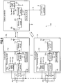
- Fig. 1 is a block diagram of a wireless communication system 100 according to a first embodiment of the present invention.
- the wireless communication system 100 is a system for performing wireless communication between a battery controller 2 as a master device, a plurality of cell controllers 1A, ---, to 1X as slave devices. As shown in Fig. 1 , the wireless communication system 100 includes cell controllers 1A, ---, to 1X, the battery controller 2, and a host system controller (controller) 3.
- Each of the cell controllers 1A, ---, to 1X as a slave device has a function of transmitting information including measured value of a voltage, a current, a temperature, etc of a battery cell group in which a battery cells c are connected in series (or individual cell c).
- the battery cell groups housed in battery packages PA to PX are used to, for example level outputs of wind power generation or solar power generation.
- the present invention is not limited to this.
- the cell controller 1A includes at least a measuring device 11, a processing circuit 12, a wireless circuit 13, and an antenna 14.
- the measuring device 11 is a sensor for detecting a voltage, a current, a temperature, etc. of the battery cell group and installed in the battery package PA.
- the processing circuit 12 is a circuit for performing a predetermined process based on the measurement result of the measuring device 11 and includes a power supply circuit 12a, a detection section 12b, a processing section 12c, and a storing section 12d.
- the power supply circuit 12a is a circuit for generating an operational voltage for respective circuits, i.e., a power supply voltage V cc with respect to a voltage Vdd on the negative side, using the battery cell group as a power source.
- the detection section 12b is an A/D converter which obtains detection information of the battery cell c based on the measurement value of the measuring device 11.
- the processing section 12c is a CPU ((Central Processing Unit) diagnoses a state of the battery cell c (a charged state, a deterioration state, presence/absent of overcurent and overvoltage) based on the detection information inputted from the detection section 12b.
- the storing section 12d stores identification information of the cell controller 1A, etc. in addition to the above-described detection information and diagnosis result.
- the wireless circuit 13 is a circuit for outputting predetermined information read out from the storing section 12d by the processing section 12c to the antenna 14.
- the wireless circuit 13 has a function of demodulating the radio signal received by the antenna 14 and supplying the demodulated signal to the processing section 12c.
- the antenna transmits and receives the wireless signal and is connected to the wireless circuit 13.
- cell controllers such as a cell controller 1X have the same configuration as the cell controller 1A.
- the battery controller 2 which is a master device, has functions of performing wireless communication with the cell controllers 1A, ---, to 1X, which are slave devices, and obtaining the above-described information (the detection information and the diagnosis result of the battery cell c, identification information of the cell controllers 1A, ---, to 1X, etc) from the cell controllers 1A, ---, to 1X.
- the battery controller 2 includes a power supply circuit 21, a battery 22, a storing section 23, a processing section 24, a wireless circuit 25, and an antenna 26.
- the power supply circuit 21 is a circuit for generating an operational voltage for respective circuits.
- the battery 22 is a power source for the power supply circuit 21 and connected to the power supply circuit 21. Accordingly, it is also possible to supply an electric power to the power supply circuit 21 from an external power supply (not shown).
- the storing section 23 stores a predetermined program executed by the processing circuit 24, the identification information, etc. of the cell controllers 1A, ---, to 1X. More specifically, on a side of the battery controller 2 (master device side), the number of the cell controllers 1A, ---, to 1X (respective slave devices) and identification information of the cell controllers 1A, ---, to 1X are grasped.
- the processing circuit 24 has a function of a "communication establishment process" with the cell controllers 1A, ---, to 1X in response to a command from the host system controller 3 described later.
- the "communication establishment process” described above is a process of establishing wireless communication between the battery controller 2 and each of the cell controllers 1A, ---, to 1X, i.e., a process of performing an initial connection.
- the processing section 24 has a function of obtaining information about the battery cells c by periodically performing wireless communication with the cell controllers 1A, ---, to 1X after performing the "communication establishment process".
- the wireless circuit 25 is a circuit which supplies predetermined information read out from the storing section 23 by the processing section 24 to the antenna 26 as a wireless signal.
- the wireless circuit 25 has a function of demodulating the wireless signal received by the antenna 26 and supplying the demodulated signal to the processing section 24.
- the antenna 26 is for transmitting and receiving the wireless signal and connected to the wireless circuit 25.
- the host system controller 3 is configured (not shown) with electronic circuits (not shown) including a CPU (Central Processing Unit), a ROM (Read Only Memory), a RAM (Random Access Memory), and various types of interfaces, etc. Further, the host system controller 3 is configured to perform various processes by the CPU after loading on the RAM the program stored in the ROM.
- the host system controller 3 is connected through a wiring K to the battery controller 2 and configured to transmit a starting command for "communication establishment process" (a start command for the initial connection) to the battery controller 2.
- the wireless communication system 100 includes two of the cell controllers 1A, 1B. Further, the battery controller 2 is described as "master device” and the two cell controllers 1A, 1B as “slave devices A, B".
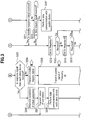
- Figs. 2 and 3 are illustrations showing processes executed by the host system controller, the master device, and the slave devices A, B.
- the processes of the slave devices A and B are integrally shown. Actually, the processes of the slave devices A, B are performed individually.
- a step S101 the host system controller 3 transits the start command of the initial connection to the master device. More specifically, the host system controller 3 transmits the start command of the "communication establishment process" described above to the master device.
- the process of the step S101 is executed at, for example, start-up of the battery controller 2, which is a master device, or resetting after stop of the battery controller 2.
- the master device Upon reception of the start command for the initial connection from the host system controller 3, the master device transmits (broadcasts) packet signals of a frequency f1 to the slave devices A, B.
- N of frequencies f1, f2, to fN are set to each of the master device and the slave devices A, B to perform wireless communication between the master device and the slave devices A, B. While successively switching these frequencies f1, f2, ---, to fN in a first cycle ⁇ t ⁇ (see Fig. 4 ), the master device wirelessly transmits the packet signals to the slave devices A, B, respectively.
- the master device In a step S201 in Fig. 2 , first, the master device tries to have the initial connection with the slave devices A, B by continuously broadcasting the packet signals of the frequency f1.
- the slave devices A, B perform a "switching process" in which a plurality of the frequencies f1, f2, ---, to fN used for its own device are successively switched at a second cycle ⁇ t ⁇ which is shorter than the first cycle ⁇ t ⁇ (see Fig. 4 ).
- the "switching process” will be described in explanation of the following steps S301 to S306.
- each of the slave devices A, B sets the receiving frequency of the packet signal to the frequency f1. Though not shown in Fig. 2 , a state that the receiving frequency in the slave devices is set to the frequency f1 which continues for a period of the second cycle ⁇ t ⁇ (see Fig. 4 ).
- a step S302 the slave device A determines whether or not the slave device A has been able to receive the packet signal from the master device at the frequency f1.
- processing of the slave device A proceeds to a step S307.
- the processing of the slave device A proceeds to a step S303.
- the slave device A sets the receiving frequency of the packet signal to a frequency f2.
- a step S304 the slave device A determines whether or not the slave device A has been able to receive the packet signal from the master device at the frequency f2.
- processing of the slave device A proceeds to a step S307.
- the processing of the slave device A switches the receiving frequency to a frequency f3.
- the slave device A tries to receive the packet signal while switching the receiving frequency of its own device at a higher speed than the master device.
- the slave device A sets the receiving frequency to a frequency fN.
- a step S306 the slave device A determines whether or not the slave device A has been able to receive the packet signal at the frequency fN.
- processing of the slave device A proceeds to the step S307.
- the processing of the slave device A proceeds to a step S312 in Fig. 3 .
- Fig. 4 is a time chart of wireless communication between the master device and the slave devices A and B and shows a state that the slave device A receives a packet signal and the slave device B has not being able to receive the packet signal.
- the master device slowly switch the frequency of the packet signal at the first cycle ⁇ t ⁇
- the slave devices A, B switch the receiving frequency of the packet signal at a high speed at the second cycle ⁇ t ⁇ .
- Such switching of the frequencies is performed asynchronously between the master device and the slave devices A, B and between the slave devices A and B.
- first cycle ⁇ t ⁇ and the second cycle ⁇ t ⁇ are set so that the slave devices A, B can switch all frequencies f1, f2 to fN while the master device continuously transmits the packet signals of the frequency fk (k is a given natural number). More specifically, there is a relation of the first cycle ⁇ t ⁇ > N ⁇ second cycle ⁇ t ⁇ .
- the switching is enabled at shipping from a factory in the slave devices A, B, i.e., the cell controllers 1A, 1B.
- the slave device A continues receiving from the master device using the receiving frequency when the packet signal can be received.
- the slave device A continuously uses the predetermined frequency as its own receiving frequency at least until the slave device receives a response request signal from the master device. This makes it possible to receive the response request signal on the side of the slave device A when the master device transmits the response request signal.
- the slave device A continuously uses the frequency f(N - 2) as the receiving frequency (see time t1 to t2).
- the slave device B cannot to receive the packet signal, so that the switching process of the frequencies f1, f1, ---, to fN is repeated. For example, if the slave device B is installed at a Null point at which the wireless signals are cancelled out each other, or if the slave device B receive an influence of a wireless signal leaked out from another wireless system (not shown), the slave device B may be unable to receive the packet signal. Depending on change in the circumstance, the slave device B may become able to receive the packet signal.
- the master device After the master device transmits the packet signal of the frequency f1 in the step S201, the master device transmits (broadcasts) the response request signal at the frequency f1 to each of the slave devices A, B in a step S202.
- the slave device A which continues receiving in the step S307, determines in a step S308 whether or not the response request signal has been received from the master device.
- processing of the slave device A proceeds to a step S309.
- the slave device A transmits the response signal to the master device wirelessly in the step S309.
- the slave device A starts sleeping in S310.
- the above-described “sleeping” is a process of temporarily stopping transmission and reception of the wireless signals. Though omission is made in Fig. 2 , "sleeping" in the step S310 is continued only for the first predetermined interval ⁇ t G shown in Fig. 4 .
- the first predetermined interval ⁇ t G is a time interval in which the sleeping is continued from time when the response signal is transmitted to the master device to have setting to enable to receive a standby request signal described later (or a data request signal) from the master device. As described above, once sleeping is made after transmitting the response signal, This provides saving energy of the slave device A.
- the master device After transmitting the response request signal in the step S202 in Fig. 2 , the master device determines in a step S203 in Fig. 3 whether or not the response signals have been received from the slave devices A, B, respectively. Out of the slave devices A, B, if there is a slave device which does not transmits the response signal (No, in the step S203), processing of the master device proceeds to a step S204.
- the master device transmits (broadcasts) the standby request signal to the slave device A which has transmitted the response signal.
- the above-described "standby request signal" is a signal requiring the slave device A having transmitted the response signal to perform the switching process again to prepare to receive the packet signal after that. Transmitting the standby request signal can cause the slave device A having already transmitted the response signal to perform the switching process of the frequency again.
- the master device transmits the packet signal of the frequency f2 in a step S205. Though omission is made in Fig. 3 , when the wireless communication is not established at the frequency f2, the frequency of the packet signal is successively changed on the side of the master device in such an order of frequencies f3, f4,---,fN, f1, f2,---fN,---.
- the slave device A which has been sleeping in the step S310 in Fig. 2 , continues sleeping for a first predetermined interval ⁇ t G as described above, and after this, determines whether or not the slave device A has received a standby request signal from the master device in a step S311 in Fig. 3 .
- a receiving frequency at this instance is the same as the frequency used for transmitting the response signal in the step S309.
- processing of the slave device A proceeds to the step S312 in Fig. 3 .
- the slave device A performs the switching process of the frequency again to switch the receiving frequency to frequencies f1, f2, ---, to fN.
- the master device determines that the initial connection has completed between the master device and the slave devices A, B in a step S206. In other words, when receiving the response signals from the respective slave devices A, B, the master device determines that communication between the slave devices A and B has been established.
- the "communication establishment process" for establishing the communication between the master device and each of the slave devices A, B includes the processing in the steps S201 to S206 and the steps S301 to the S315 shown in Figs. 2 and 3 .
- the master device transmits a completion notice of the initial connection to the host system controller 3. Accordingly, a manager of the wireless communication system 100 can grasp the completion of the initial connection between the master device and the slave devices A, B.
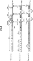
- Fig. 5 is a time charts of the wireless communication between the master device and the slave devices A, B and indicates a case where both the slave devices A, B receive the packet signal.
- both the slave devices A, B transmit the response signals at a frequency f(N-2) to the master device.
- f(N-2) a frequency f(N-2)
- the master device performs data communication with the slave devices A, B. Though omission is made in Fig. 3 , upon performing data communication, the master device transmits (broadcasts) a data request signal to each of the slave devices A, B.
- step S316 On the side of the slave device, when a standby request signal cannot be received from the master device in the step S311 (No in the step S311), processing of the slave device A proceeds to a step S316.
- the slave device A determines whether or not the slave device A has received the data request signal from the master device in the step S316. When the slave device A has received the data request signal (Yes in the step S316), processing of a slave device A proceeds to a step S317.
- the slave device A performs a data communication with the master device.
- the slave devices A, B perform sleeping (S310) after transmitting the response signals at the frequency f(N - 2)(S309). After sleeping for the first predetermined interval ⁇ t G , the slave devices A, B set the receiving frequency to the frequency f(N-2) and wait for the data request signal from the master device (or standby request signal) (S311,S316).
- each of the slave devices A, B receives the data request signal from the master device in the step S316 in Fig. 3 (Yes in the step S316), in response to this, each of the slave devices A and B sets the receiving frequency to the frequency f(N-2), and transmits data including the voltage, the current, the temperature, the charged state, etc of the battery cell c (see Fig. 1 ) to the master device ((S317). Further, when there is an error in the battery cell c, it is also possible that the master device inform of this the host system controller 3.
- the invention is not limited to this. More specifically, it is also possible to properly change the frequency used for the data communication after completion of the initial connection to improve the communication quality.
- the master device transmits the packet signals to the slave devices A, B while the frequency is switched at the first interval ⁇ t ⁇ , and the slave devices A, B switch the receiving frequency at the second ⁇ t ⁇ which is shorter than the above-described first interval ⁇ t ⁇ .
- the frequency used for the wireless communication can be suitably set in accordance with installation circumferences of the master device and the slave devices A, B. Further, it is possible to handle addition or replacement of the battery packages housing a plurality of the battery cells c (see Fig. 1 ) easily and flexibly.
- the communication communication establishment process is performed asynchronously, it is not necessary to install circuits for synchronous operation in the master device or the slave devices A, B. According to the present embodiment, it is possible to reduce a manufacturing cost of the master device and the slave devices A, B from that of the conventional devices. Further, because the communication communication establishment process is performed in response to the command from the host system controller 3, it is possible to make the cost for the communication establishment lower than that in the case where an operator manually set the frequency, and to reduce the man-hour of the operator for the communication establishment significantly.
- a cost for wirings can be reduced from the conventional technology in which the communication was made using cables.
- Fig. 9 is a block diagram of a wire communication system 200 of a comparative example.
- a battery controller (master device) is wired-connected through wiring to the cell controllers (slave devices).
- the cell controllers slave devices
- a large number for example, thousands, tens of millions
- cell controllers are installed accordingly.
- a cost for wiring for connecting the battery controller to the cell controller is high, and a much man-hour is required for the wiring.
- the present embodiment provides the system for wireless communication between the master device and each of the slave devices, so that a cost for wirings is low and it is possible to easy perform the initial connection between the master device and each of the slave devices.
- the second embodiment is different from the first embodiment in that the interval from reception of the response request signal from the master device to transmission of the response signal is different among the slave devices A, B, ---, to X (see Fig. 6 ).
- the interval from reception of the response request signal from the master device to transmission of the response signal is different among the slave devices A, B, ---, to X (see Fig. 6 ).
- other configurations and operations are the same as those of the first embodiment. Accordingly, only a part which is different from the first embodiment is described below and a description of the duplicated part is omitted.
- Fig. 6 is an illustration showing a process executed by the master device and the slave devices A, B, ---, to X in a wireless communication system according to a second embodiment of the present invention.
- step S202 in Fig. 6 corresponds to the step S202 (see Fig. 2 ) described in the first embodiment.
- steps S309a, S310a correspond to the steps S309, S310 (see Fig. 2 ) in Fig. 2 described in the first embodiment, respectively.
- steps S309b, S310b, S309x, and S310x have similar correspondence.
- the master device transmits (broadcasts) a response request signal to the slave devices A, B, --- to X.
- the slave device A determines in a step S331a whether or not a predetermined interval ⁇ t1 has passed from reception of the response request signal.
- a predetermined interval ⁇ t1 has not passed from the reception of the response request signal (No in the step S331a)
- the slave device A repeats the process in the step S331a.
- processing of the slave device A proceeds to the step S309a.
- the slave device A transmits the response signal to the master device. After this, the slave device A starts sleeping in the step S310a.
- a slave device B transmits the response signal to the master device (S309b).
- the slave device X transmits a response signal (S309x).
- the predetermined intervals ⁇ t1, ⁇ t2, ---, to ⁇ tx from the reception of the response request signal to transmission of the response signal are different among the slave devices A, B, ---, to X. This prevents collision (interference) between the response signals transmitted to the master device from the slave devices A, B, --- to X.
- Fig. 7 is a time chart of the wireless communication between the master device and slave devices A, B, ---, to X and shows a state that timing at which each slave devices transmits the response signal is shifted. As shown in Fig. 7 , the master device transmits the response request signal to the slave devices A, B, --- to X at every predetermined communication slot.
- the initial connection has not completed, and the master device transmits the response request signals repeatedly.
- the standby request signal described in the first embodiment is transmitted from the master device between the response request signal in this cycle and the response request signal in the next cycle.
- a value of the above-described predetermined interval ⁇ t1 is zero, and there is a magnitude relation of the predetermined intervals ⁇ t1, ⁇ t2, ---, to ⁇ tx is ⁇ t1 ⁇ ⁇ t2 ⁇ ---, ⁇ tx.
- lengths of the predetermined intervals ⁇ t1, ⁇ t2, ---, ⁇ tx are different each other. This prevents collision of the response signals transmitted from the slave devices A, B, ---, to X from the master device. As a result, the master device side can surly receive the response signals from the slave devices A, B, ---, to X.
- the response signals and predetermined data are transmitted at different timing from the slave devices A, B, --- to X to the master device. This prevents collisions of signals (response signal and data) transmitted from the slave device A, B,--, to X.
- Fig. 8 is a time chart of the wireless communication between the master device and the slave devices A, B.
- Fig. 8 indicates a state in which the master device has not started the communication establishment process described in the first embodiment yet, i.e., a state in which the master device has not been started up), and thus any packet signal has not been transmitted by the master device.
- the slave devices A, B are set to repeat the switching process of the receiving frequency at shipping from a factory.
- the slave devices A, B are set to alternately repeat the switching process of the frequency between f1, f2, ---, to N and the sleeping for a second predetermined interval ⁇ t R . Further, while the communication communication establishment process is performed between the master device and the slave devices A, B, on the side of the slave devices A, B, the switching process of the frequency and the sleeping are repeated alternately. Such an intermittent reception is made, which can reduce the power consumption of the slave devices A, B. Accordingly, this suppresses decrease in the charged quantity of the battery cell c (see Fig. 2 ) supplying electric powers to the slave devices A, B even when the master device has not started up or the master device has not been able to transmit the packet signal due to an error in the master device.
- the switching process of the frequency (the steps S312 to S315) is immediately performed on the side of the slave devices A, B when the response request signal from the master device has not been received.
- the present invention is not limited to this. More specifically, when the response request signal cannot be received even when a "third predetermined interval" has passed from reception of the packet signal from the master device, it is also possible that the slave devices A, B alternately repeat the switching process of the frequency and the sleeping . This reduces the power consumptions in the slave devices A, B.
- the present invention is not limited to this. More specifically, when there is one or more of slave devices which does not transmit the response signal at all of the frequencies f1, f2, --- to fN, it is also possible that the master device specifies the frequency at which a larger number of the slave devices out of the slave devices transmit the response signals and establishes the communication at the specified frequency, and determine that the slave device which did not transit the response signal, is "failed". This can establish the communication between the master device with the normal slave devices even when there is a failed slave device.
- the present invention is not limited to this. More specifically, it is also possible to connect the host system controller 3 and the master device wirelessly.
- the wireless communication system includes a plurality of the battery controllers 2
- the host system controller 3 as a master device and a plurality of the battery controllers 2 as slave devices to perform the communication communication establishment process.
- the wireless communication system may have a hierarchical configuration having a plurality of stages. The communication establishment process between each of devices is the same as that in the first embodiment.
- the master device may starts up the communication communication establishment process by a predetermined switching operation.
- each of the slave devices includes a real time clock and setting is made that timing of transmitting the packet signal from the slave device to the master device is different from each other. This prevents collision between the packet signals transmitted from respective slave devices.
- the embodiments may be combined suitably.
- a configuration provided by combining the second embodiment and the third embodiment in which each of the slave devices alternately performs the switching process of the receiving frequency see Fig. 8
- it is also possible to set time from reception of the response request signal to transmission of the response signal to different predetermined intervals see Fig. 7 ).
- the wireless communication system 100 (see Fig. 1 ) for managing a plurality of cell groups has be described in each of the embodiments.
- the present invention is not limited to this. More specifically, the wireless communication system 100 can be applied to a battery system for in-vehicle use, a high voltage battery system for railway use or industrial use, a battery logistic management system, an article management system, a sensor net system, etc.
Landscapes
- Engineering & Computer Science (AREA)
- Computer Networks & Wireless Communication (AREA)
- Signal Processing (AREA)
- Databases & Information Systems (AREA)
- Mobile Radio Communication Systems (AREA)
Abstract
Description
- The present invention relates to a wireless communication system performing wireless communication between a master device and slave devices.
- Communication systems including a master device and a plurality of slave devices for wired communication one master device to one slave device through cables, have been used conventionally. Such a wire communication system requires a high installation cost in wirings and connection of wirings requires much man power. Then, a wireless communication system for wireless communication between a master device and a plurality of slave device in place of the wire communication system, has been proposed.
- For example,
Patent Document 1 disclosed as follows:
In a wireless communication performed between a vehicle and a mobile device, the vehicle periodically receives twochannels channel 1, thechannel 2 is used on a priority basis. -
Document 2 disclosed as follows:
When a wireless communication device starts communication with a wireless base station, the wireless communicating device receives a signal from the wireless communication base station in a predetermined frequency hopping pattern while timing synchronization is performed, and replaces a frequency having interference with a spare frequency. -
- PATENT DOCUMENT1:
JP2009-177767 - PATENT DOCUMENT2:
JP2005-33416 - PATENT DOCUMENT1 disclosed that a technology for improving a communication quality in a state that communication has been established between the vehicle and the mobile device. However, PATENT DOCUMENT1 fails to disclose a technology to establish a connection of wireless communication, i.e., a technology of performing initial connection.
- In PATENT DOCUMENT2, a frequency of interference in communication is calculated while timing synchronization is performed between the wireless base station and a wireless communication device. This invites increase in cost because circuits or the like for timing synchronization should be installed in the master device and the slave devices.
- A problem in the present invention is to provide a communication system at a low cost for establishing the wireless communication connection.
- To solve the problem, an aspect of the present invention provides a wireless communication system comprising:
- a master device and a plurality of slave devices capable of wireless communication with the master device,
- wherein a plurality of frequencies for wireless communication between the master device and the slave devices, are set to each of the master device and the slave devices ;
- wherein as a communication establishment process for establishing communication between the master device and each of the slave devices,
- the master device wirelessly transmits a packet signal to each of the slave devices, while switching is made among a plurality of the frequencies at a first cycle;
- each of the slave devices performs a switching process of switching among a plurality of the frequencies usable as an own receiving frequency at a second cycle shorter than the first cycle until the slave device can receive the packet signal from the master device;
- upon reception of the packet signal from the master device, each of the slave devices wirelessly transmits a response signal to the master device in response to the response request signal from the master device after the reception of the packet signal; and
- when the master device receives the response signal from each of the slave devices, the master device determines that the communication has established with each of the slave devices.
- According to the present invention, a wireless communication system can be provided, which requires a low cost for establishing the wireless communication connection.
-
-
Fig. 1 is a block diagram of a wireless communication system according to a first embodiment of the present invention. -
Fig. 2 is an illustration showing a process executed by a host system controller, a master device, and slave devices. -
Fig. 3 is an illustration showing a process executed by a host system controller, a master device, and slave devices. -
Fig. 4 is a time chart of wireless communication between the master device and the slave devices A and B and shows a state that the slave device A receives a packet signal and the slave device B has not being able to receive the packet signal. -
Fig. 5 is a time chart of wireless communication between the master device and the slave devices A and B and shows a state that both the slave devices A and B have received the packet signal. -
Fig. 6 is an illustration showing a process executed by the master device and the slave devices in a wireless communication system according to a second embodiment of the present invention. -
Fig. 7 is a time chart of the wireless communication between the master device and slave devices and shows a state that timing at which each of slave devices transmits a response signal, is shifted. -
Fig. 8 is a time chart of wireless communication between the master device and the slave devices A and B in a wireless communication system according to a modification embodiment of the present invention. -
Fig. 9 is a block diagram of a wire communication system of a comparative example. -
Fig. 1 is a block diagram of awireless communication system 100 according to a first embodiment of the present invention. - The
wireless communication system 100 is a system for performing wireless communication between abattery controller 2 as a master device, a plurality ofcell controllers 1A, ---, to 1X as slave devices. As shown inFig. 1 , thewireless communication system 100 includescell controllers 1A, ---, to 1X, thebattery controller 2, and a host system controller (controller) 3. - Each of the
cell controllers 1A, ---, to 1X as a slave device has a function of transmitting information including measured value of a voltage, a current, a temperature, etc of a battery cell group in which a battery cells c are connected in series (or individual cell c). The battery cell groups housed in battery packages PA to PX are used to, for example level outputs of wind power generation or solar power generation. However, the present invention is not limited to this. - As shown in
Fig. 1 , thecell controller 1A includes at least ameasuring device 11, aprocessing circuit 12, awireless circuit 13, and anantenna 14. - The
measuring device 11 is a sensor for detecting a voltage, a current, a temperature, etc. of the battery cell group and installed in the battery package PA. Theprocessing circuit 12 is a circuit for performing a predetermined process based on the measurement result of themeasuring device 11 and includes apower supply circuit 12a, adetection section 12b, aprocessing section 12c, and astoring section 12d. - The
power supply circuit 12a is a circuit for generating an operational voltage for respective circuits, i.e., a power supply voltage Vcc with respect to a voltage Vdd on the negative side, using the battery cell group as a power source. Thedetection section 12b is an A/D converter which obtains detection information of the battery cell c based on the measurement value of themeasuring device 11. Theprocessing section 12c is a CPU ((Central Processing Unit) diagnoses a state of the battery cell c (a charged state, a deterioration state, presence/absent of overcurent and overvoltage) based on the detection information inputted from thedetection section 12b. The storingsection 12d stores identification information of thecell controller 1A, etc. in addition to the above-described detection information and diagnosis result. - The
wireless circuit 13 is a circuit for outputting predetermined information read out from thestoring section 12d by theprocessing section 12c to theantenna 14. Thewireless circuit 13 has a function of demodulating the radio signal received by theantenna 14 and supplying the demodulated signal to theprocessing section 12c. The antenna transmits and receives the wireless signal and is connected to thewireless circuit 13. - Other cell controllers such as a
cell controller 1X have the same configuration as thecell controller 1A. - The
battery controller 2, which is a master device, has functions of performing wireless communication with thecell controllers 1A, ---, to 1X, which are slave devices, and obtaining the above-described information (the detection information and the diagnosis result of the battery cell c, identification information of thecell controllers 1A, ---, to 1X, etc) from thecell controllers 1A, ---, to 1X. As shown inFig. 1 , thebattery controller 2 includes apower supply circuit 21, abattery 22, astoring section 23, aprocessing section 24, awireless circuit 25, and anantenna 26. - The
power supply circuit 21 is a circuit for generating an operational voltage for respective circuits. Thebattery 22 is a power source for thepower supply circuit 21 and connected to thepower supply circuit 21. Accordingly, it is also possible to supply an electric power to thepower supply circuit 21 from an external power supply (not shown). - The storing
section 23 stores a predetermined program executed by theprocessing circuit 24, the identification information, etc. of thecell controllers 1A, ---, to 1X. More specifically, on a side of the battery controller 2 (master device side), the number of thecell controllers 1A, ---, to 1X (respective slave devices) and identification information of thecell controllers 1A, ---, to 1X are grasped. - The
processing circuit 24 has a function of a "communication establishment process" with thecell controllers 1A, ---, to 1X in response to a command from thehost system controller 3 described later. The "communication establishment process" described above is a process of establishing wireless communication between thebattery controller 2 and each of thecell controllers 1A, ---, to 1X, i.e., a process of performing an initial connection. - The
processing section 24 has a function of obtaining information about the battery cells c by periodically performing wireless communication with thecell controllers 1A, ---, to 1X after performing the "communication establishment process". - The
wireless circuit 25 is a circuit which supplies predetermined information read out from the storingsection 23 by theprocessing section 24 to theantenna 26 as a wireless signal. Thewireless circuit 25 has a function of demodulating the wireless signal received by theantenna 26 and supplying the demodulated signal to theprocessing section 24. Theantenna 26 is for transmitting and receiving the wireless signal and connected to thewireless circuit 25. - The
host system controller 3 is configured (not shown) with electronic circuits (not shown) including a CPU (Central Processing Unit), a ROM (Read Only Memory), a RAM (Random Access Memory), and various types of interfaces, etc. Further, thehost system controller 3 is configured to perform various processes by the CPU after loading on the RAM the program stored in the ROM. Thehost system controller 3 is connected through a wiring K to thebattery controller 2 and configured to transmit a starting command for "communication establishment process" (a start command for the initial connection) to thebattery controller 2. - Hereinafter, a description is made as an example in which the
wireless communication system 100 includes two of thecell controllers 1A, 1B. Further, thebattery controller 2 is described as "master device" and the twocell controllers 1A, 1B as "slave devices A, B". -
Figs. 2 and3 are illustrations showing processes executed by the host system controller, the master device, and the slave devices A, B. InFigs. 2 and3 , the processes of the slave devices A and B are integrally shown. Actually, the processes of the slave devices A, B are performed individually. - In a step S101, the
host system controller 3 transits the start command of the initial connection to the master device. More specifically, thehost system controller 3 transmits the start command of the "communication establishment process" described above to the master device. The process of the step S101 is executed at, for example, start-up of thebattery controller 2, which is a master device, or resetting after stop of thebattery controller 2. - Upon reception of the start command for the initial connection from the
host system controller 3, the master device transmits (broadcasts) packet signals of a frequency f1 to the slave devices A, B. - N of frequencies f1, f2, to fN are set to each of the master device and the slave devices A, B to perform wireless communication between the master device and the slave devices A, B. While successively switching these frequencies f1, f2, ---, to fN in a first cycle Δtα (see
Fig. 4 ), the master device wirelessly transmits the packet signals to the slave devices A, B, respectively. In a step S201 inFig. 2 , first, the master device tries to have the initial connection with the slave devices A, B by continuously broadcasting the packet signals of the frequency f1. - On the other hand, the slave devices A, B perform a "switching process" in which a plurality of the frequencies f1, f2, ---, to fN used for its own device are successively switched at a second cycle Δtβ which is shorter than the first cycle Δtα (see
Fig. 4 ). The "switching process" will be described in explanation of the following steps S301 to S306. - In the step S301, each of the slave devices A, B sets the receiving frequency of the packet signal to the frequency f1. Though not shown in
Fig. 2 , a state that the receiving frequency in the slave devices is set to the frequency f1 which continues for a period of the second cycle Δtβ (seeFig. 4 ). - Hereinafter, out of the slave devices A and B, the process of the slave device A is mainly described below. However, the process of a slave device B is similar to this.
- In a step S302, the slave device A determines whether or not the slave device A has been able to receive the packet signal from the master device at the frequency f1. When the slave device A has been able to receive the packet signal at the frequency f1 (Yes in the step S302), processing of the slave device A proceeds to a step S307. On the other hand, when the slave device A has not being able to receive the packet signal at the frequency f1 (No in the step S302), the processing of the slave device A proceeds to a step S303.
- In the step S303, the slave device A sets the receiving frequency of the packet signal to a frequency f2.
- In a step S304, the slave device A determines whether or not the slave device A has been able to receive the packet signal from the master device at the frequency f2. When the slave device A could receive the packet signal at the frequency f2 (Yes in the step S304), processing of the slave device A proceeds to a step S307. On the other hand, when the slave device A has not been able to receive the packet signal at the frequency f2 (No in the step S304), though it is not shown in
Fig. 2 , the processing of the slave device A switches the receiving frequency to a frequency f3. As described above, the slave device A tries to receive the packet signal while switching the receiving frequency of its own device at a higher speed than the master device. - In a step S305, the slave device A sets the receiving frequency to a frequency fN.
- In a step S306, the slave device A determines whether or not the slave device A has been able to receive the packet signal at the frequency fN. When the slave device A has been able to receive the packet signal at the frequency fN (Yes, in the step S306), processing of the slave device A proceeds to the step S307. On the other hand, when the slave device A has not been able to receive the packet signal at the frequency fN (No, in the step S306), the processing of the slave device A proceeds to a step S312 in
Fig. 3 . -
Fig. 4 is a time chart of wireless communication between the master device and the slave devices A and B and shows a state that the slave device A receives a packet signal and the slave device B has not being able to receive the packet signal. - As shown in
Fig. 4 , the master device slowly switch the frequency of the packet signal at the first cycle Δtα, and the slave devices A, B switch the receiving frequency of the packet signal at a high speed at the second cycle Δtβ. Such switching of the frequencies is performed asynchronously between the master device and the slave devices A, B and between the slave devices A and B. - Further, the first cycle Δtα and the second cycle Δtβ are set so that the slave devices A, B can switch all frequencies f1, f2 to fN while the master device continuously transmits the packet signals of the frequency fk (k is a given natural number). More specifically, there is a relation of the first cycle Δtα > N × second cycle Δtβ.
- Regarding this, it is also possible that the switching is enabled at shipping from a factory in the slave devices A, B, i.e., the
cell controllers 1A, 1B. Alternatively, it is possible to start switching of the receiving frequency by a switching operation by an operator. - In the step S307 in
Fig. 2 , the slave device A continues receiving from the master device using the receiving frequency when the packet signal can be received. In other words, when the slave device A receives a predetermined frequency from the master device, the slave device A continuously uses the predetermined frequency as its own receiving frequency at least until the slave device receives a response request signal from the master device. This makes it possible to receive the response request signal on the side of the slave device A when the master device transmits the response request signal. - In the example shown in
Fig. 4 , until the slave device A receives the response request signal from the master device after receiving the packet signal at the frequency f(N - 2) from the master device, the slave device A continuously uses the frequency f(N - 2) as the receiving frequency (see time t1 to t2). - On the other hand, the slave device B cannot to receive the packet signal, so that the switching process of the frequencies f1, f1, ---, to fN is repeated. For example, if the slave device B is installed at a Null point at which the wireless signals are cancelled out each other, or if the slave device B receive an influence of a wireless signal leaked out from another wireless system (not shown), the slave device B may be unable to receive the packet signal. Depending on change in the circumstance, the slave device B may become able to receive the packet signal.
- Returning to
Fig. 2 again, description is continued. - After the master device transmits the packet signal of the frequency f1 in the step S201, the master device transmits (broadcasts) the response request signal at the frequency f1 to each of the slave devices A, B in a step S202.
- The slave device A, which continues receiving in the step S307, determines in a step S308 whether or not the response request signal has been received from the master device. When the slave device A receives the response request signal from the master device (Yes in S308), processing of the slave device A proceeds to a step S309.
- The slave device A transmits the response signal to the master device wirelessly in the step S309.
- The slave device A starts sleeping in S310. The above-described "sleeping" is a process of temporarily stopping transmission and reception of the wireless signals. Though omission is made in
Fig. 2 , "sleeping" in the step S310 is continued only for the first predetermined interval ΔtG shown inFig. 4 . The first predetermined interval ΔtG is a time interval in which the sleeping is continued from time when the response signal is transmitted to the master device to have setting to enable to receive a standby request signal described later (or a data request signal) from the master device. As described above, once sleeping is made after transmitting the response signal, This provides saving energy of the slave device A. - After transmitting the response request signal in the step S202 in
Fig. 2 , the master device determines in a step S203 inFig. 3 whether or not the response signals have been received from the slave devices A, B, respectively. Out of the slave devices A, B, if there is a slave device which does not transmits the response signal (No, in the step S203), processing of the master device proceeds to a step S204. - The master device transmits (broadcasts) the standby request signal to the slave device A which has transmitted the response signal. The above-described "standby request signal" is a signal requiring the slave device A having transmitted the response signal to perform the switching process again to prepare to receive the packet signal after that. Transmitting the standby request signal can cause the slave device A having already transmitted the response signal to perform the switching process of the frequency again.
- The master device transmits the packet signal of the frequency f2 in a step S205. Though omission is made in
Fig. 3 , when the wireless communication is not established at the frequency f2, the frequency of the packet signal is successively changed on the side of the master device in such an order of frequencies f3, f4,---,fN, f1, f2,---fN,---. - The slave device A, which has been sleeping in the step S310 in
Fig. 2 , continues sleeping for a first predetermined interval ΔtG as described above, and after this, determines whether or not the slave device A has received a standby request signal from the master device in a step S311 inFig. 3 . A receiving frequency at this instance is the same as the frequency used for transmitting the response signal in the step S309. - When the slave device A has received the standby request signal from the master device in the step S311 (Yes in the step S311), processing of the slave device A proceeds to the step S312 in
Fig. 3 . In the steps S312 to S315, the slave device A performs the switching process of the frequency again to switch the receiving frequency to frequencies f1, f2, ---, to fN. - Though not shown in
Fig. 3 , it is also possible to resume performing the switching process of the frequency after the slave device A sleeps only for a predetermined interval ΔtH (seeFig. 4 ) when the slave device A receives the standby request signal. At this phase, communication between themaster device 1 and the slave devices A, B has not been established. This is because the side of the slave device B cannot receive the packet signal, i.e., the slave device B has not transmitted the response signal toward the master device. - In the step S203 in
Fig. 3 , when receiving response signals from the slave devices A, B (Yes in the S203), the master device determines that the initial connection has completed between the master device and the slave devices A, B in a step S206. In other words, when receiving the response signals from the respective slave devices A, B, the master device determines that communication between the slave devices A and B has been established. - The "communication establishment process" for establishing the communication between the master device and each of the slave devices A, B includes the processing in the steps S201 to S206 and the steps S301 to the S315 shown in
Figs. 2 and3 . - Next, in the step S207, the master device transmits a completion notice of the initial connection to the
host system controller 3. Accordingly, a manager of thewireless communication system 100 can grasp the completion of the initial connection between the master device and the slave devices A, B. -
Fig. 5 is a time charts of the wireless communication between the master device and the slave devices A, B and indicates a case where both the slave devices A, B receive the packet signal. - In the example shown in
Fig. 5 , in response to the response request signal from the master device, both the slave devices A, B transmit the response signals at a frequency f(N-2) to the master device. As a result, on the side of the master device, it is determined that the wireless communication has been established between the master device and the slave devices A, B (Yes in S203 and S206). - In a step S208 in
Fig. 3 , the master device performs data communication with the slave devices A, B. Though omission is made inFig. 3 , upon performing data communication, the master device transmits (broadcasts) a data request signal to each of the slave devices A, B. - On the side of the slave device, when a standby request signal cannot be received from the master device in the step S311 (No in the step S311), processing of the slave device A proceeds to a step S316.
- The slave device A determines whether or not the slave device A has received the data request signal from the master device in the step S316. When the slave device A has received the data request signal (Yes in the step S316), processing of a slave device A proceeds to a step S317.
- In the step S317, the slave device A performs a data communication with the master device.
- As shown in
Fig. 5 , after completion of the initial connection, the data communication is periodically performed between the master device and the slave devices A, B. In the example shown inFig. 5 , the slave devices A, B perform sleeping (S310) after transmitting the response signals at the frequency f(N - 2)(S309). After sleeping for the first predetermined interval ΔtG, the slave devices A, B set the receiving frequency to the frequency f(N-2) and wait for the data request signal from the master device (or standby request signal) (S311,S316). - When each of the slave devices A, B receives the data request signal from the master device in the step S316 in
Fig. 3 (Yes in the step S316), in response to this, each of the slave devices A and B sets the receiving frequency to the frequency f(N-2), and transmits data including the voltage, the current, the temperature, the charged state, etc of the battery cell c (seeFig. 1 ) to the master device ((S317). Further, when there is an error in the battery cell c, it is also possible that the master device inform of this thehost system controller 3. - In the example shown in
Fig. 5 , using the frequency f(N-2) when the initial connection can be established, the data communication after this is performed. However, the invention is not limited to this. More specifically, it is also possible to properly change the frequency used for the data communication after completion of the initial connection to improve the communication quality. - In the present embodiment, the master device transmits the packet signals to the slave devices A, B while the frequency is switched at the first interval Δtα, and the slave devices A, B switch the receiving frequency at the second Δtβ which is shorter than the above-described first interval Δtα. As described above, since the communication establishing process is performed asynchronously, the frequency used for the wireless communication can be suitably set in accordance with installation circumferences of the master device and the slave devices A, B. Further, it is possible to handle addition or replacement of the battery packages housing a plurality of the battery cells c (see
Fig. 1 ) easily and flexibly. - Further, as described above, because the communication communication establishment process is performed asynchronously, it is not necessary to install circuits for synchronous operation in the master device or the slave devices A, B. According to the present embodiment, it is possible to reduce a manufacturing cost of the master device and the slave devices A, B from that of the conventional devices. Further, because the communication communication establishment process is performed in response to the command from the
host system controller 3, it is possible to make the cost for the communication establishment lower than that in the case where an operator manually set the frequency, and to reduce the man-hour of the operator for the communication establishment significantly. - Further, in the present embodiment in which the master device and the slave devices A, B perform the wireless communication, a cost for wirings can be reduced from the conventional technology in which the communication was made using cables.
-
Fig. 9 is a block diagram of awire communication system 200 of a comparative example. - In the
communication system 200 shown inFig. 9 , though a detailed description is omitted, a battery controller (master device) is wired-connected through wiring to the cell controllers (slave devices). For example, in a natural energy power generation system having a large scale, a large number (for example, thousands, tens of millions) of battery cells are installed to level outputs, and cell controllers are installed accordingly. In the wired communication system shown inFig. 9 , a cost for wiring for connecting the battery controller to the cell controller is high, and a much man-hour is required for the wiring. - Contrarily to this, the present embodiment provides the system for wireless communication between the master device and each of the slave devices, so that a cost for wirings is low and it is possible to easy perform the initial connection between the master device and each of the slave devices.
- The second embodiment is different from the first embodiment in that the interval from reception of the response request signal from the master device to transmission of the response signal is different among the slave devices A, B, ---, to X (see
Fig. 6 ). However other configurations and operations are the same as those of the first embodiment. Accordingly, only a part which is different from the first embodiment is described below and a description of the duplicated part is omitted. -
Fig. 6 is an illustration showing a process executed by the master device and the slave devices A, B, ---, to X in a wireless communication system according to a second embodiment of the present invention. - The step S202 in
Fig. 6 corresponds to the step S202 (seeFig. 2 ) described in the first embodiment. Further, steps S309a, S310a correspond to the steps S309, S310 (seeFig. 2 ) inFig. 2 described in the first embodiment, respectively. Further, steps S309b, S310b, S309x, and S310x have similar correspondence. - In the step S202 in
Fig. 6 , the master device transmits (broadcasts) a response request signal to the slave devices A, B, --- to X. - The slave device A determines in a step S331a whether or not a predetermined interval Δt1 has passed from reception of the response request signal. When the predetermined interval Δt1 has not passed from the reception of the response request signal (No in the step S331a), the slave device A repeats the process in the step S331a. On the other hand, when the predetermined interval Δt1 has passed from the reception of the response request signal (Yes in the step S331a), processing of the slave device A proceeds to the step S309a.
- The slave device A transmits the response signal to the master device. After this, the slave device A starts sleeping in the step S310a.
- On the other hand, when a predetermined interval Δt2 has passed from the reception of the response request signal (Yes in the step S331b), a slave device B transmits the response signal to the master device (S309b).
- Further, when the interval Δtx has passed from the reception of the response request signal from the master device (Yes in a step S331x), the slave device X transmits a response signal (S309x).
- Here, the predetermined intervals Δt1, Δt2, ---, to Δtx from the reception of the response request signal to transmission of the response signal are different among the slave devices A, B, ---, to X. This prevents collision (interference) between the response signals transmitted to the master device from the slave devices A, B, --- to X.
-
Fig. 7 is a time chart of the wireless communication between the master device and slave devices A, B, ---, to X and shows a state that timing at which each slave devices transmits the response signal is shifted. As shown inFig. 7 , the master device transmits the response request signal to the slave devices A, B, --- to X at every predetermined communication slot. - In the example shown in
Fig. 7 , because there is a slave device which cannot receive the packet signal from the master device (for example, the slave device C (not shown), the initial connection has not completed, and the master device transmits the response request signals repeatedly. Further, though not shown inFIG. 7 , the standby request signal described in the first embodiment (in the step S204 inFig. 3 ) is transmitted from the master device between the response request signal in this cycle and the response request signal in the next cycle. - Further, in the example shown in
Fig. 7 , a value of the above-described predetermined interval Δt1 is zero, and there is a magnitude relation of the predetermined intervalsΔt1, Δt2, ---, to Δtx is Δt1 < Δt2 < ---, <Δtx. As described above, lengths of the predetermined intervals Δt1, Δt2, ---, Δtx are different each other. This prevents collision of the response signals transmitted from the slave devices A, B, ---, to X from the master device. As a result, the master device side can surly receive the response signals from the slave devices A, B, ---, to X. - As described, similar to shifting the transmission timing of the response signals at the slave devices A, B, --- to X, it is also possible to shift timing of transmitting predetermined data to the master device at the slave devices A, B, --- to X after completion of the communication establishment process. More specifically, it is also possible to set intervals from the reception of the predetermined data request signal from the master device to transmission of data corresponding to the data request signal to a different interval for each of the slave devices A, B, --- to X after completion of the communication establishment process described in the first embodiment. This prevents collision (interference) between the data transmitted from the slave devices A, B, --- to X to the master device.
- According to the present embodiment, the response signals and predetermined data are transmitted at different timing from the slave devices A, B, --- to X to the master device. This prevents collisions of signals (response signal and data) transmitted from the slave device A, B,--, to X.
- Embodiments regarding the
wireless communication system 100 according to the present invention have been described. The present invention is not limited to the above-described embodiments and there are various modifications. -
Fig. 8 is a time chart of the wireless communication between the master device and the slave devices A, B. -
Fig. 8 indicates a state in which the master device has not started the communication establishment process described in the first embodiment yet, i.e., a state in which the master device has not been started up), and thus any packet signal has not been transmitted by the master device. On the other hand, for example, the slave devices A, B are set to repeat the switching process of the receiving frequency at shipping from a factory. - As shown in
Fig. 8 , the slave devices A, B are set to alternately repeat the switching process of the frequency between f1, f2, ---, to N and the sleeping for a second predetermined interval ΔtR. Further, while the communication communication establishment process is performed between the master device and the slave devices A, B, on the side of the slave devices A, B, the switching process of the frequency and the sleeping are repeated alternately. Such an intermittent reception is made, which can reduce the power consumption of the slave devices A, B. Accordingly, this suppresses decrease in the charged quantity of the battery cell c (seeFig. 2 ) supplying electric powers to the slave devices A, B even when the master device has not started up or the master device has not been able to transmit the packet signal due to an error in the master device. - Further, in the switching process of the frequency at the slave devices A, B, as shown in
Fig. 8 , it is also possible to perform the switching between the frequencies f1, f2, ---, to fN plural times. - Further, in the first embodiment, descriptions have been made for a configuration in which the switching process of the frequency (the steps S312 to S315) is immediately performed on the side of the slave devices A, B when the response request signal from the master device has not been received. However, the present invention is not limited to this. More specifically, when the response request signal cannot be received even when a "third predetermined interval" has passed from reception of the packet signal from the master device, it is also possible that the slave devices A, B alternately repeat the switching process of the frequency and the sleeping . This reduces the power consumptions in the slave devices A, B.
- In the first embedment, descriptions have been made for the process of determining that the initial connection has completed by the master device (the step S206) when the response signals from the all slave devices are received (Yes in the step S203 in
Fig. 3 ). However, the present invention is not limited to this. More specifically, when there is one or more of slave devices which does not transmit the response signal at all of the frequencies f1, f2, --- to fN, it is also possible that the master device specifies the frequency at which a larger number of the slave devices out of the slave devices transmit the response signals and establishes the communication at the specified frequency, and determine that the slave device which did not transit the response signal, is "failed". This can establish the communication between the master device with the normal slave devices even when there is a failed slave device. - Further, in the above-described configuration, it is also possible to transmit the identification information of the failure slave device to the
host system controller 3 from the master device. This makes it possible to know the failed slave device on the side of the manager of thewireless communication system 100 and perform repair. - Further, in each of the embodiments, the descriptions have been made for the configurations in which the
host system controller 3 and the master device are wire-connected through the wiring K (seeFig. 1 ). However, the present invention is not limited to this. More specifically, it is also possible to connect thehost system controller 3 and the master device wirelessly. - Further, in the configuration in which the wireless communication system includes a plurality of the
battery controllers 2, it is also possible to use thehost system controller 3 as a master device and a plurality of thebattery controllers 2 as slave devices to perform the communication communication establishment process. In other words, the wireless communication system may have a hierarchical configuration having a plurality of stages. The communication establishment process between each of devices is the same as that in the first embodiment. - Further, it is also possible to omit the
host system controller 3 from the first embodiment, and, for example, the master device may starts up the communication communication establishment process by a predetermined switching operation. - Further, in each of the embodiments, the processes in which the master device transmits the packet signals to each of the slave devices and each of the slave devices performs the switching process of the receiving frequency, have been described. However, the present invention is not limited to this. For example, it is also possible to establish the communication by a plurality of slave devices transmitting the packet signals to the master device while switching the frequency at the first cycle Δtα and the master device performing switching operation of the receiving frequency at a second cycle Δtβ (<Δtα). In this configuration, each of the slave devices includes a real time clock and setting is made that timing of transmitting the packet signal from the slave device to the master device is different from each other. This prevents collision between the packet signals transmitted from respective slave devices.
- Further, the embodiments may be combined suitably. For example, in a configuration provided by combining the second embodiment and the third embodiment in which each of the slave devices alternately performs the switching process of the receiving frequency (see
Fig. 8 ), it is also possible to set time from reception of the response request signal to transmission of the response signal to different predetermined intervals (seeFig. 7 ). - Further, the wireless communication system 100 (see
Fig. 1 ) for managing a plurality of cell groups has be described in each of the embodiments. However, the present invention is not limited to this. More specifically, thewireless communication system 100 can be applied to a battery system for in-vehicle use, a high voltage battery system for railway use or industrial use, a battery logistic management system, an article management system, a sensor net system, etc. - Each of the embodiments is described in detail for easy understanding the present invention, and not limited to an embodiment including all configurations described above. Further, it is possible that another configuration is added to a part of the configuration of the embodiment, the part is deleted, or the part is replaced with other configurations. Further, the above-described mechanism and configuration indicate what is considered necessary for explanation, and not all mechanisms and configurations are shown for products.
-
- 100 wireless communication system
- 1A, --- 1X cell controller (slave device)
- 2 battery controller (master device)
- 3 host system controller (controller)
- 11 measuring device
- c battery cell
Claims (11)
- A wireless communication system comprising:a master device and a plurality of slave devices capable of wireless communication with the master device,wherein a plurality of frequencies for wireless communication between the master device and the slave devices, are set to each of the master device and the slave devices ;wherein as a communication establishment process for establishing communication between the master device and each of the slave devices,the master device wirelessly transmits a packet signal to each of the slave devices, while switching is made among a plurality of the frequencies at a first cycle;each of the slave devices performs a switching process of switching among a plurality of the frequencies usable as an own receiving frequency at a second cycle shorter than the first cycle until the slave device can receive the packet signal from the master device;upon reception of the packet signal from the master device, each of the slave devices wirelessly transmits a response signal to the master device in response to the response request signal from the master device after the reception of the packet signal; andwhen the master device receives the response signal from each of the slave devices, the master device determines that the communication has established with each of the slave devices.
- The wireless communication system as claimed in claim 1, wherein when the slave device receives the packet signal from the master device at a predetermined frequency, the slave device continuously uses the predetermined frequency as the own receiving frequency at least until the slave device receives the response request signal from the master device.
- The wireless communication system as claimed in claim 1, wherein in the communication establishment process, when there is one of the slave devices which has not transmitted the response signal, the master device transmits to the slave devices having transmitted the response signals a standby request signal for requesting to perform the switching process again in preparation for receiving the packet signal.
- The wireless communication system as claimed in claim 3, wherein in the communication establishment process, when one of the slave devices having transmitted the response signal, transmits the response signal and then performs sleeping for a first predetermined interval and then, receives the standby request signal at the frequency at which the response signal was transmitted.
- The wireless communication system as claimed in claim 1, wherein an interval from reception of the response request signal to transmission of the response signal is set to a different time length among the slave devices.
- The wireless communication system as claimed in claim 1, wherein after completion of the communication establishment process, an interval from reception of a predetermined data request signal from the master device to transmission of the data corresponding to the data request signal are set to a different time length among the slave devices.
- The wireless communication system as claimed in claim 1, wherein the slave device alternately repeats the switching process and the sleeping for the second predetermined interval.
- The wireless communication system as claimed in claim 1, wherein the slave device alternately repeats the switching process and the sleeping when the slave device does not receive the response request signal though a third predetermined interval has passed from the reception of the packet signal from the master device.
- The wireless communication system as claimed in claim 1, wherein when there is one of the slave devices which has not transmitted the response signal at all of the frequencies, the master device specifies one of the frequencies at which the number of slave devices which transmitted the response signal, is largest, establishes communication at the one of the frequencies, and determines that the slave device which has not transmitted the response signal at all of the frequencies is failed.
- The wireless communication system as claimed in claim 1, further comprises a controller connected to the master device by wire or wirelessly, wherein the master device performs the communication establishment process in response to a command from the controller.
- The wireless communication system as claimed in any one of claims 1 to 10, wherein a plurality of the slave devices comprise cell controllers and the master device comprises a battery controller each obtaining data including measurement value by performing the wireless communication with the cell controller.
Applications Claiming Priority (2)
| Application Number | Priority Date | Filing Date | Title |
|---|---|---|---|
| JP2016114192 | 2016-06-08 | ||
| PCT/JP2017/020956 WO2017213128A1 (en) | 2016-06-08 | 2017-06-06 | Wireless communication system |
Publications (3)
| Publication Number | Publication Date |
|---|---|
| EP3471501A1 true EP3471501A1 (en) | 2019-04-17 |
| EP3471501A4 EP3471501A4 (en) | 2020-03-25 |
| EP3471501B1 EP3471501B1 (en) | 2021-02-17 |
Family
ID=60578677
Family Applications (1)
| Application Number | Title | Priority Date | Filing Date |
|---|---|---|---|
| EP17810303.2A Not-in-force EP3471501B1 (en) | 2016-06-08 | 2017-06-06 | System for communication establishment between a master device and a plurality of slave devices |
Country Status (5)
| Country | Link |
|---|---|
| EP (1) | EP3471501B1 (en) |
| JP (1) | JP6519710B2 (en) |
| KR (1) | KR102132315B1 (en) |
| CN (1) | CN109315002A (en) |
| WO (1) | WO2017213128A1 (en) |
Families Citing this family (3)
| Publication number | Priority date | Publication date | Assignee | Title |
|---|---|---|---|---|
| DE102020115333A1 (en) * | 2019-06-17 | 2020-12-17 | Silicon Works Co., Ltd. | Wireless battery management system, wireless communication nodes and data transfer methods |
| JP7571740B2 (en) * | 2022-01-31 | 2024-10-23 | トヨタ自動車株式会社 | Communication control device |
| JP2024049713A (en) * | 2022-09-29 | 2024-04-10 | シャープ株式会社 | COMMUNICATION SYSTEM, SLANT STATION, COMMUNICATION METHOD, AND COMMUNICATION PROGRAM |
Family Cites Families (14)
| Publication number | Priority date | Publication date | Assignee | Title |
|---|---|---|---|---|
| JP2004200940A (en) * | 2002-12-17 | 2004-07-15 | Dainippon Printing Co Ltd | Wireless communication system |
| JP2004274520A (en) * | 2003-03-11 | 2004-09-30 | Casio Comput Co Ltd | Terminal communication system and program |
| JP4385665B2 (en) * | 2003-07-10 | 2009-12-16 | パナソニック株式会社 | Wireless communication apparatus and communication system |
| JP3719254B2 (en) | 2003-07-10 | 2005-11-24 | 松下電器産業株式会社 | Frequency hopping wireless communication device |
| GB2408896B (en) * | 2003-12-06 | 2007-12-12 | Zarlink Semiconductor Ab | Method of selecting appropriate wireless characteristics for geographic location |
| US8619658B2 (en) * | 2005-09-21 | 2013-12-31 | Interdigital Technology Corporation | Method and apparatus for transmission management in a wireless communication system |
| JP2009177767A (en) | 2007-12-27 | 2009-08-06 | Tokai Rika Co Ltd | Channel selective communication system |
| JP5332840B2 (en) * | 2009-04-08 | 2013-11-06 | ソニー株式会社 | Wireless communication apparatus, wireless communication system, wireless communication method, and program |
| WO2012114738A1 (en) * | 2011-02-22 | 2012-08-30 | パナソニック株式会社 | Wireless communication system and wireless slave and master units used therein |
| KR101029499B1 (en) * | 2011-03-09 | 2011-04-18 | 엘아이지넥스원 주식회사 | Frequency Synchronization Device and Method in Packet-Based Frequency Hopping Communication System |
| JP5879294B2 (en) * | 2013-03-29 | 2016-03-08 | 日立オートモティブシステムズ株式会社 | Battery system |
| JP2015005870A (en) * | 2013-06-20 | 2015-01-08 | シャープ株式会社 | Radio master unit, radio slave unit, and radio data communication system |
| WO2015098003A1 (en) * | 2013-12-26 | 2015-07-02 | 日本電気株式会社 | Connection control method for communication terminal |
| JP2016032143A (en) * | 2014-07-28 | 2016-03-07 | 長野日本無線株式会社 | Communication terminal and data collection system |
-
2017
- 2017-06-06 CN CN201780035415.4A patent/CN109315002A/en active Pending
- 2017-06-06 WO PCT/JP2017/020956 patent/WO2017213128A1/en not_active Ceased
- 2017-06-06 EP EP17810303.2A patent/EP3471501B1/en not_active Not-in-force
- 2017-06-06 JP JP2018522503A patent/JP6519710B2/en active Active
- 2017-06-06 KR KR1020187035281A patent/KR102132315B1/en not_active Expired - Fee Related
Also Published As
| Publication number | Publication date |
|---|---|
| CN109315002A (en) | 2019-02-05 |
| WO2017213128A1 (en) | 2017-12-14 |
| KR102132315B1 (en) | 2020-07-09 |
| JPWO2017213128A1 (en) | 2018-10-04 |
| JP6519710B2 (en) | 2019-05-29 |
| KR20190004342A (en) | 2019-01-11 |
| EP3471501A4 (en) | 2020-03-25 |
| EP3471501B1 (en) | 2021-02-17 |
Similar Documents
| Publication | Publication Date | Title |
|---|---|---|
| JP6392088B2 (en) | Wireless battery system and cell controller and battery controller used therefor | |
| US10319218B2 (en) | Wireless battery system, and wireless system | |
| KR101526413B1 (en) | Transceiver ic and operationg mwethod thereof | |
| EP1821419A2 (en) | Communication method, communication system and communication apparatus | |
| EP3471501B1 (en) | System for communication establishment between a master device and a plurality of slave devices | |
| US12445318B2 (en) | Bus system and support device comprising such a bus system | |
| US20060282506A1 (en) | Communication master station startup period control method | |
| US6021356A (en) | Control system using programmable logic controller | |
| JP6619800B2 (en) | Wireless base station and system including the wireless base station | |
| EP1821248A2 (en) | Channel search method and communication apparatus using the same | |
| KR100201209B1 (en) | Telemeter. Telecontrol System | |
| JP2010271897A (en) | Wireless meter reading system | |
| US11513163B2 (en) | Voltage detection circuit for voltage measurement apparatus for use in assembled battery system | |
| US20170284201A1 (en) | Malfunction diagnosis apparatus for gear motor | |
| KR100246906B1 (en) | Programmable controller network system | |
| US20110211512A1 (en) | Frame generation device, reception device, data transmission/reception system, frame generation method, and reception method | |
| KR100726476B1 (en) | A Time Synchronization Method for Minimizing Power Consumption of Heterogeneous Sensor Nodes and Its Network | |
| JP3611062B2 (en) | Telemeter / telecontrol system | |
| CN116133012B (en) | Communication device, test method, system, equipment and storage medium | |
| JP6897484B2 (en) | Battery communication system and battery communication method | |
| US8638776B2 (en) | Frame generating device, receiving device, data transmitting/receiving system, frame generating method, and receiving method | |
| JP6808742B2 (en) | Wireless battery system | |
| CN102325032A (en) | A kind of method of the real-time communication of supplying power | |
| JP6169854B2 (en) | Communication system and communication method | |
| CN113992555B (en) | Automatic testing method and system for main node network |
Legal Events
| Date | Code | Title | Description |
|---|---|---|---|
| STAA | Information on the status of an ep patent application or granted ep patent |
Free format text: STATUS: THE INTERNATIONAL PUBLICATION HAS BEEN MADE |
|
| PUAI | Public reference made under article 153(3) epc to a published international application that has entered the european phase |
Free format text: ORIGINAL CODE: 0009012 |
|
| STAA | Information on the status of an ep patent application or granted ep patent |
Free format text: STATUS: REQUEST FOR EXAMINATION WAS MADE |
|
| 17P | Request for examination filed |
Effective date: 20190108 |
|
| AK | Designated contracting states |
Kind code of ref document: A1 Designated state(s): AL AT BE BG CH CY CZ DE DK EE ES FI FR GB GR HR HU IE IS IT LI LT LU LV MC MK MT NL NO PL PT RO RS SE SI SK SM TR |
|
| AX | Request for extension of the european patent |
Extension state: BA ME |
|
| DAV | Request for validation of the european patent (deleted) | ||
| DAX | Request for extension of the european patent (deleted) | ||
| REG | Reference to a national code |
Ref country code: DE Ref legal event code: R079 Ref document number: 602017032875 Country of ref document: DE Free format text: PREVIOUS MAIN CLASS: H04W0076020000 Ipc: H04W0008000000 |
|
| A4 | Supplementary search report drawn up and despatched |
Effective date: 20200226 |
|
| RIC1 | Information provided on ipc code assigned before grant |
Ipc: H04W 8/00 20090101AFI20200220BHEP Ipc: H04W 84/18 20090101ALI20200220BHEP Ipc: H04W 76/10 20180101ALI20200220BHEP |
|
| GRAP | Despatch of communication of intention to grant a patent |
Free format text: ORIGINAL CODE: EPIDOSNIGR1 |
|
| STAA | Information on the status of an ep patent application or granted ep patent |
Free format text: STATUS: GRANT OF PATENT IS INTENDED |
|
| INTG | Intention to grant announced |
Effective date: 20200827 |
|
| RIN1 | Information on inventor provided before grant (corrected) |
Inventor name: YAMAZOE, TAKANORI Inventor name: SAKABE, KEI Inventor name: ARITA, HIROSHI |
|
| GRAS | Grant fee paid |
Free format text: ORIGINAL CODE: EPIDOSNIGR3 |
|
| GRAA | (expected) grant |
Free format text: ORIGINAL CODE: 0009210 |
|
| STAA | Information on the status of an ep patent application or granted ep patent |
Free format text: STATUS: THE PATENT HAS BEEN GRANTED |
|
| RAP1 | Party data changed (applicant data changed or rights of an application transferred) |
Owner name: SHOWA DENKO MATERIALS CO., LTD. |
|
| AK | Designated contracting states |
Kind code of ref document: B1 Designated state(s): AL AT BE BG CH CY CZ DE DK EE ES FI FR GB GR HR HU IE IS IT LI LT LU LV MC MK MT NL NO PL PT RO RS SE SI SK SM TR |
|
| REG | Reference to a national code |
Ref country code: GB Ref legal event code: FG4D |
|
| REG | Reference to a national code |
Ref country code: CH Ref legal event code: EP |
|
| REG | Reference to a national code |
Ref country code: DE Ref legal event code: R096 Ref document number: 602017032875 Country of ref document: DE |
|
| REG | Reference to a national code |
Ref country code: AT Ref legal event code: REF Ref document number: 1363132 Country of ref document: AT Kind code of ref document: T Effective date: 20210315 |
|
| REG | Reference to a national code |
Ref country code: IE Ref legal event code: FG4D |
|
| REG | Reference to a national code |
Ref country code: LT Ref legal event code: MG9D |
|
| REG | Reference to a national code |
Ref country code: NL Ref legal event code: MP Effective date: 20210217 |
|
| PG25 | Lapsed in a contracting state [announced via postgrant information from national office to epo] |
Ref country code: BG Free format text: LAPSE BECAUSE OF FAILURE TO SUBMIT A TRANSLATION OF THE DESCRIPTION OR TO PAY THE FEE WITHIN THE PRESCRIBED TIME-LIMIT Effective date: 20210517 Ref country code: LT Free format text: LAPSE BECAUSE OF FAILURE TO SUBMIT A TRANSLATION OF THE DESCRIPTION OR TO PAY THE FEE WITHIN THE PRESCRIBED TIME-LIMIT Effective date: 20210217 Ref country code: HR Free format text: LAPSE BECAUSE OF FAILURE TO SUBMIT A TRANSLATION OF THE DESCRIPTION OR TO PAY THE FEE WITHIN THE PRESCRIBED TIME-LIMIT Effective date: 20210217 Ref country code: FI Free format text: LAPSE BECAUSE OF FAILURE TO SUBMIT A TRANSLATION OF THE DESCRIPTION OR TO PAY THE FEE WITHIN THE PRESCRIBED TIME-LIMIT Effective date: 20210217 Ref country code: GR Free format text: LAPSE BECAUSE OF FAILURE TO SUBMIT A TRANSLATION OF THE DESCRIPTION OR TO PAY THE FEE WITHIN THE PRESCRIBED TIME-LIMIT Effective date: 20210518 Ref country code: NO Free format text: LAPSE BECAUSE OF FAILURE TO SUBMIT A TRANSLATION OF THE DESCRIPTION OR TO PAY THE FEE WITHIN THE PRESCRIBED TIME-LIMIT Effective date: 20210517 Ref country code: PT Free format text: LAPSE BECAUSE OF FAILURE TO SUBMIT A TRANSLATION OF THE DESCRIPTION OR TO PAY THE FEE WITHIN THE PRESCRIBED TIME-LIMIT Effective date: 20210617 |
|
| REG | Reference to a national code |
Ref country code: AT Ref legal event code: MK05 Ref document number: 1363132 Country of ref document: AT Kind code of ref document: T Effective date: 20210217 |
|
| PG25 | Lapsed in a contracting state [announced via postgrant information from national office to epo] |
Ref country code: RS Free format text: LAPSE BECAUSE OF FAILURE TO SUBMIT A TRANSLATION OF THE DESCRIPTION OR TO PAY THE FEE WITHIN THE PRESCRIBED TIME-LIMIT Effective date: 20210217 Ref country code: NL Free format text: LAPSE BECAUSE OF FAILURE TO SUBMIT A TRANSLATION OF THE DESCRIPTION OR TO PAY THE FEE WITHIN THE PRESCRIBED TIME-LIMIT Effective date: 20210217 Ref country code: PL Free format text: LAPSE BECAUSE OF FAILURE TO SUBMIT A TRANSLATION OF THE DESCRIPTION OR TO PAY THE FEE WITHIN THE PRESCRIBED TIME-LIMIT Effective date: 20210217 Ref country code: LV Free format text: LAPSE BECAUSE OF FAILURE TO SUBMIT A TRANSLATION OF THE DESCRIPTION OR TO PAY THE FEE WITHIN THE PRESCRIBED TIME-LIMIT Effective date: 20210217 Ref country code: SE Free format text: LAPSE BECAUSE OF FAILURE TO SUBMIT A TRANSLATION OF THE DESCRIPTION OR TO PAY THE FEE WITHIN THE PRESCRIBED TIME-LIMIT Effective date: 20210217 |
|
| PG25 | Lapsed in a contracting state [announced via postgrant information from national office to epo] |
Ref country code: IS Free format text: LAPSE BECAUSE OF FAILURE TO SUBMIT A TRANSLATION OF THE DESCRIPTION OR TO PAY THE FEE WITHIN THE PRESCRIBED TIME-LIMIT Effective date: 20210617 |
|
| PG25 | Lapsed in a contracting state [announced via postgrant information from national office to epo] |
Ref country code: AT Free format text: LAPSE BECAUSE OF FAILURE TO SUBMIT A TRANSLATION OF THE DESCRIPTION OR TO PAY THE FEE WITHIN THE PRESCRIBED TIME-LIMIT Effective date: 20210217 Ref country code: SM Free format text: LAPSE BECAUSE OF FAILURE TO SUBMIT A TRANSLATION OF THE DESCRIPTION OR TO PAY THE FEE WITHIN THE PRESCRIBED TIME-LIMIT Effective date: 20210217 Ref country code: CZ Free format text: LAPSE BECAUSE OF FAILURE TO SUBMIT A TRANSLATION OF THE DESCRIPTION OR TO PAY THE FEE WITHIN THE PRESCRIBED TIME-LIMIT Effective date: 20210217 Ref country code: EE Free format text: LAPSE BECAUSE OF FAILURE TO SUBMIT A TRANSLATION OF THE DESCRIPTION OR TO PAY THE FEE WITHIN THE PRESCRIBED TIME-LIMIT Effective date: 20210217 |
|
| REG | Reference to a national code |
Ref country code: DE Ref legal event code: R097 Ref document number: 602017032875 Country of ref document: DE |
|
| PG25 | Lapsed in a contracting state [announced via postgrant information from national office to epo] |
Ref country code: RO Free format text: LAPSE BECAUSE OF FAILURE TO SUBMIT A TRANSLATION OF THE DESCRIPTION OR TO PAY THE FEE WITHIN THE PRESCRIBED TIME-LIMIT Effective date: 20210217 Ref country code: DK Free format text: LAPSE BECAUSE OF FAILURE TO SUBMIT A TRANSLATION OF THE DESCRIPTION OR TO PAY THE FEE WITHIN THE PRESCRIBED TIME-LIMIT Effective date: 20210217 Ref country code: SK Free format text: LAPSE BECAUSE OF FAILURE TO SUBMIT A TRANSLATION OF THE DESCRIPTION OR TO PAY THE FEE WITHIN THE PRESCRIBED TIME-LIMIT Effective date: 20210217 |
|
| PLBE | No opposition filed within time limit |
Free format text: ORIGINAL CODE: 0009261 |
|
| STAA | Information on the status of an ep patent application or granted ep patent |
Free format text: STATUS: NO OPPOSITION FILED WITHIN TIME LIMIT |
|
| 26N | No opposition filed |
Effective date: 20211118 |
|
| PG25 | Lapsed in a contracting state [announced via postgrant information from national office to epo] |
Ref country code: ES Free format text: LAPSE BECAUSE OF FAILURE TO SUBMIT A TRANSLATION OF THE DESCRIPTION OR TO PAY THE FEE WITHIN THE PRESCRIBED TIME-LIMIT Effective date: 20210217 Ref country code: AL Free format text: LAPSE BECAUSE OF FAILURE TO SUBMIT A TRANSLATION OF THE DESCRIPTION OR TO PAY THE FEE WITHIN THE PRESCRIBED TIME-LIMIT Effective date: 20210217 Ref country code: MC Free format text: LAPSE BECAUSE OF FAILURE TO SUBMIT A TRANSLATION OF THE DESCRIPTION OR TO PAY THE FEE WITHIN THE PRESCRIBED TIME-LIMIT Effective date: 20210217 |
|
| REG | Reference to a national code |
Ref country code: CH Ref legal event code: PL |
|
| PG25 | Lapsed in a contracting state [announced via postgrant information from national office to epo] |
Ref country code: SI Free format text: LAPSE BECAUSE OF FAILURE TO SUBMIT A TRANSLATION OF THE DESCRIPTION OR TO PAY THE FEE WITHIN THE PRESCRIBED TIME-LIMIT Effective date: 20210217 |
|
| REG | Reference to a national code |
Ref country code: BE Ref legal event code: MM Effective date: 20210630 |
|
| PG25 | Lapsed in a contracting state [announced via postgrant information from national office to epo] |
Ref country code: LU Free format text: LAPSE BECAUSE OF NON-PAYMENT OF DUE FEES Effective date: 20210606 |
|
| PG25 | Lapsed in a contracting state [announced via postgrant information from national office to epo] |
Ref country code: LI Free format text: LAPSE BECAUSE OF NON-PAYMENT OF DUE FEES Effective date: 20210630 Ref country code: IT Free format text: LAPSE BECAUSE OF FAILURE TO SUBMIT A TRANSLATION OF THE DESCRIPTION OR TO PAY THE FEE WITHIN THE PRESCRIBED TIME-LIMIT Effective date: 20210217 Ref country code: IE Free format text: LAPSE BECAUSE OF NON-PAYMENT OF DUE FEES Effective date: 20210606 Ref country code: CH Free format text: LAPSE BECAUSE OF NON-PAYMENT OF DUE FEES Effective date: 20210630 |
|
| PG25 | Lapsed in a contracting state [announced via postgrant information from national office to epo] |
Ref country code: IS Free format text: LAPSE BECAUSE OF FAILURE TO SUBMIT A TRANSLATION OF THE DESCRIPTION OR TO PAY THE FEE WITHIN THE PRESCRIBED TIME-LIMIT Effective date: 20210617 Ref country code: FR Free format text: LAPSE BECAUSE OF NON-PAYMENT OF DUE FEES Effective date: 20210630 |
|
| PG25 | Lapsed in a contracting state [announced via postgrant information from national office to epo] |
Ref country code: BE Free format text: LAPSE BECAUSE OF NON-PAYMENT OF DUE FEES Effective date: 20210630 |
|
| PG25 | Lapsed in a contracting state [announced via postgrant information from national office to epo] |
Ref country code: CY Free format text: LAPSE BECAUSE OF FAILURE TO SUBMIT A TRANSLATION OF THE DESCRIPTION OR TO PAY THE FEE WITHIN THE PRESCRIBED TIME-LIMIT Effective date: 20210217 |
|
| PG25 | Lapsed in a contracting state [announced via postgrant information from national office to epo] |
Ref country code: HU Free format text: LAPSE BECAUSE OF FAILURE TO SUBMIT A TRANSLATION OF THE DESCRIPTION OR TO PAY THE FEE WITHIN THE PRESCRIBED TIME-LIMIT; INVALID AB INITIO Effective date: 20170606 |
|
| PG25 | Lapsed in a contracting state [announced via postgrant information from national office to epo] |
Ref country code: MK Free format text: LAPSE BECAUSE OF FAILURE TO SUBMIT A TRANSLATION OF THE DESCRIPTION OR TO PAY THE FEE WITHIN THE PRESCRIBED TIME-LIMIT Effective date: 20210217 |
|
| PG25 | Lapsed in a contracting state [announced via postgrant information from national office to epo] |
Ref country code: TR Free format text: LAPSE BECAUSE OF FAILURE TO SUBMIT A TRANSLATION OF THE DESCRIPTION OR TO PAY THE FEE WITHIN THE PRESCRIBED TIME-LIMIT Effective date: 20210217 |
|
| PGFP | Annual fee paid to national office [announced via postgrant information from national office to epo] |
Ref country code: GB Payment date: 20240620 Year of fee payment: 8 |
|
| PGFP | Annual fee paid to national office [announced via postgrant information from national office to epo] |
Ref country code: DE Payment date: 20240630 Year of fee payment: 8 |
|
| PG25 | Lapsed in a contracting state [announced via postgrant information from national office to epo] |
Ref country code: MT Free format text: LAPSE BECAUSE OF FAILURE TO SUBMIT A TRANSLATION OF THE DESCRIPTION OR TO PAY THE FEE WITHIN THE PRESCRIBED TIME-LIMIT Effective date: 20210217 |
|
| REG | Reference to a national code |
Ref country code: DE Ref legal event code: R119 Ref document number: 602017032875 Country of ref document: DE |
|
| GBPC | Gb: european patent ceased through non-payment of renewal fee |
Effective date: 20250606 |
|
| PG25 | Lapsed in a contracting state [announced via postgrant information from national office to epo] |
Ref country code: GB Free format text: LAPSE BECAUSE OF NON-PAYMENT OF DUE FEES Effective date: 20250606 |
|
| PG25 | Lapsed in a contracting state [announced via postgrant information from national office to epo] |
Ref country code: DE Free format text: LAPSE BECAUSE OF NON-PAYMENT OF DUE FEES Effective date: 20260101 |