EP3471242A1 - Cooling structure for rotary electric machine - Google Patents
Cooling structure for rotary electric machine Download PDFInfo
- Publication number
- EP3471242A1 EP3471242A1 EP18197510.3A EP18197510A EP3471242A1 EP 3471242 A1 EP3471242 A1 EP 3471242A1 EP 18197510 A EP18197510 A EP 18197510A EP 3471242 A1 EP3471242 A1 EP 3471242A1
- Authority
- EP
- European Patent Office
- Prior art keywords
- rotary electric
- electric machine
- supply pipe
- oil
- refrigerant
- Prior art date
- Legal status (The legal status is an assumption and is not a legal conclusion. Google has not performed a legal analysis and makes no representation as to the accuracy of the status listed.)
- Granted
Links
- 238000001816 cooling Methods 0.000 title claims abstract description 95
- 239000003507 refrigerant Substances 0.000 claims abstract description 67
- 239000003921 oil Substances 0.000 description 149
- 230000005540 biological transmission Effects 0.000 description 14
- 230000007246 mechanism Effects 0.000 description 14
- 238000005086 pumping Methods 0.000 description 10
- 238000002485 combustion reaction Methods 0.000 description 4
- 230000001965 increasing effect Effects 0.000 description 3
- 230000003993 interaction Effects 0.000 description 3
- 239000010687 lubricating oil Substances 0.000 description 3
- HBBGRARXTFLTSG-UHFFFAOYSA-N Lithium ion Chemical compound [Li+] HBBGRARXTFLTSG-UHFFFAOYSA-N 0.000 description 2
- PXHVJJICTQNCMI-UHFFFAOYSA-N Nickel Chemical compound [Ni] PXHVJJICTQNCMI-UHFFFAOYSA-N 0.000 description 2
- 239000012080 ambient air Substances 0.000 description 2
- 230000000694 effects Effects 0.000 description 2
- 239000012530 fluid Substances 0.000 description 2
- 229910001416 lithium ion Inorganic materials 0.000 description 2
- 238000005461 lubrication Methods 0.000 description 2
- 230000002093 peripheral effect Effects 0.000 description 2
- 230000000452 restraining effect Effects 0.000 description 2
- UFHFLCQGNIYNRP-UHFFFAOYSA-N Hydrogen Chemical compound [H][H] UFHFLCQGNIYNRP-UHFFFAOYSA-N 0.000 description 1
- 239000003570 air Substances 0.000 description 1
- 230000004075 alteration Effects 0.000 description 1
- 239000003990 capacitor Substances 0.000 description 1
- 239000004020 conductor Substances 0.000 description 1
- 239000002826 coolant Substances 0.000 description 1
- 230000007423 decrease Effects 0.000 description 1
- 230000002708 enhancing effect Effects 0.000 description 1
- -1 for example Substances 0.000 description 1
- 239000007789 gas Substances 0.000 description 1
- 239000001257 hydrogen Substances 0.000 description 1
- 229910052739 hydrogen Inorganic materials 0.000 description 1
- 239000007788 liquid Substances 0.000 description 1
- 229910052759 nickel Inorganic materials 0.000 description 1
- 230000001360 synchronised effect Effects 0.000 description 1
- XLYOFNOQVPJJNP-UHFFFAOYSA-N water Substances O XLYOFNOQVPJJNP-UHFFFAOYSA-N 0.000 description 1
Images


Classifications
-
- B—PERFORMING OPERATIONS; TRANSPORTING
- B60—VEHICLES IN GENERAL
- B60K—ARRANGEMENT OR MOUNTING OF PROPULSION UNITS OR OF TRANSMISSIONS IN VEHICLES; ARRANGEMENT OR MOUNTING OF PLURAL DIVERSE PRIME-MOVERS IN VEHICLES; AUXILIARY DRIVES FOR VEHICLES; INSTRUMENTATION OR DASHBOARDS FOR VEHICLES; ARRANGEMENTS IN CONNECTION WITH COOLING, AIR INTAKE, GAS EXHAUST OR FUEL SUPPLY OF PROPULSION UNITS IN VEHICLES
- B60K11/00—Arrangement in connection with cooling of propulsion units
- B60K11/02—Arrangement in connection with cooling of propulsion units with liquid cooling
-
- F—MECHANICAL ENGINEERING; LIGHTING; HEATING; WEAPONS; BLASTING
- F16—ENGINEERING ELEMENTS AND UNITS; GENERAL MEASURES FOR PRODUCING AND MAINTAINING EFFECTIVE FUNCTIONING OF MACHINES OR INSTALLATIONS; THERMAL INSULATION IN GENERAL
- F16H—GEARING
- F16H61/00—Control functions within control units of change-speed- or reversing-gearings for conveying rotary motion ; Control of exclusively fluid gearing, friction gearing, gearings with endless flexible members or other particular types of gearing
- F16H61/0021—Generation or control of line pressure
- F16H61/0025—Supply of control fluid; Pumps therefore
- F16H61/0028—Supply of control fluid; Pumps therefore using a single pump driven by different power sources
-
- F—MECHANICAL ENGINEERING; LIGHTING; HEATING; WEAPONS; BLASTING
- F16—ENGINEERING ELEMENTS AND UNITS; GENERAL MEASURES FOR PRODUCING AND MAINTAINING EFFECTIVE FUNCTIONING OF MACHINES OR INSTALLATIONS; THERMAL INSULATION IN GENERAL
- F16H—GEARING
- F16H57/00—General details of gearing
- F16H57/04—Features relating to lubrication or cooling or heating
- F16H57/0412—Cooling or heating; Control of temperature
- F16H57/0413—Controlled cooling or heating of lubricant; Temperature control therefor
-
- B—PERFORMING OPERATIONS; TRANSPORTING
- B60—VEHICLES IN GENERAL
- B60K—ARRANGEMENT OR MOUNTING OF PROPULSION UNITS OR OF TRANSMISSIONS IN VEHICLES; ARRANGEMENT OR MOUNTING OF PLURAL DIVERSE PRIME-MOVERS IN VEHICLES; AUXILIARY DRIVES FOR VEHICLES; INSTRUMENTATION OR DASHBOARDS FOR VEHICLES; ARRANGEMENTS IN CONNECTION WITH COOLING, AIR INTAKE, GAS EXHAUST OR FUEL SUPPLY OF PROPULSION UNITS IN VEHICLES
- B60K6/00—Arrangement or mounting of plural diverse prime-movers for mutual or common propulsion, e.g. hybrid propulsion systems comprising electric motors and internal combustion engines ; Control systems therefor, i.e. systems controlling two or more prime movers, or controlling one of these prime movers and any of the transmission, drive or drive units Informative references: mechanical gearings with secondary electric drive F16H3/72; arrangements for handling mechanical energy structurally associated with the dynamo-electric machine H02K7/00; machines comprising structurally interrelated motor and generator parts H02K51/00; dynamo-electric machines not otherwise provided for in H02K see H02K99/00
- B60K6/20—Arrangement or mounting of plural diverse prime-movers for mutual or common propulsion, e.g. hybrid propulsion systems comprising electric motors and internal combustion engines ; Control systems therefor, i.e. systems controlling two or more prime movers, or controlling one of these prime movers and any of the transmission, drive or drive units Informative references: mechanical gearings with secondary electric drive F16H3/72; arrangements for handling mechanical energy structurally associated with the dynamo-electric machine H02K7/00; machines comprising structurally interrelated motor and generator parts H02K51/00; dynamo-electric machines not otherwise provided for in H02K see H02K99/00 the prime-movers consisting of electric motors and internal combustion engines, e.g. HEVs
- B60K6/22—Arrangement or mounting of plural diverse prime-movers for mutual or common propulsion, e.g. hybrid propulsion systems comprising electric motors and internal combustion engines ; Control systems therefor, i.e. systems controlling two or more prime movers, or controlling one of these prime movers and any of the transmission, drive or drive units Informative references: mechanical gearings with secondary electric drive F16H3/72; arrangements for handling mechanical energy structurally associated with the dynamo-electric machine H02K7/00; machines comprising structurally interrelated motor and generator parts H02K51/00; dynamo-electric machines not otherwise provided for in H02K see H02K99/00 the prime-movers consisting of electric motors and internal combustion engines, e.g. HEVs characterised by apparatus, components or means specially adapted for HEVs
- B60K6/26—Arrangement or mounting of plural diverse prime-movers for mutual or common propulsion, e.g. hybrid propulsion systems comprising electric motors and internal combustion engines ; Control systems therefor, i.e. systems controlling two or more prime movers, or controlling one of these prime movers and any of the transmission, drive or drive units Informative references: mechanical gearings with secondary electric drive F16H3/72; arrangements for handling mechanical energy structurally associated with the dynamo-electric machine H02K7/00; machines comprising structurally interrelated motor and generator parts H02K51/00; dynamo-electric machines not otherwise provided for in H02K see H02K99/00 the prime-movers consisting of electric motors and internal combustion engines, e.g. HEVs characterised by apparatus, components or means specially adapted for HEVs characterised by the motors or the generators
-
- F—MECHANICAL ENGINEERING; LIGHTING; HEATING; WEAPONS; BLASTING
- F04—POSITIVE - DISPLACEMENT MACHINES FOR LIQUIDS; PUMPS FOR LIQUIDS OR ELASTIC FLUIDS
- F04B—POSITIVE-DISPLACEMENT MACHINES FOR LIQUIDS; PUMPS
- F04B23/00—Pumping installations or systems
- F04B23/04—Combinations of two or more pumps
-
- F—MECHANICAL ENGINEERING; LIGHTING; HEATING; WEAPONS; BLASTING
- F16—ENGINEERING ELEMENTS AND UNITS; GENERAL MEASURES FOR PRODUCING AND MAINTAINING EFFECTIVE FUNCTIONING OF MACHINES OR INSTALLATIONS; THERMAL INSULATION IN GENERAL
- F16H—GEARING
- F16H57/00—General details of gearing
- F16H57/04—Features relating to lubrication or cooling or heating
- F16H57/0467—Elements of gearings to be lubricated, cooled or heated
- F16H57/0476—Electric machines and gearing, i.e. joint lubrication or cooling or heating thereof
-
- F—MECHANICAL ENGINEERING; LIGHTING; HEATING; WEAPONS; BLASTING
- F16—ENGINEERING ELEMENTS AND UNITS; GENERAL MEASURES FOR PRODUCING AND MAINTAINING EFFECTIVE FUNCTIONING OF MACHINES OR INSTALLATIONS; THERMAL INSULATION IN GENERAL
- F16H—GEARING
- F16H59/00—Control inputs to control units of change-speed-, or reversing-gearings for conveying rotary motion
- F16H59/68—Inputs being a function of gearing status
- F16H59/72—Inputs being a function of gearing status dependent on oil characteristics, e.g. temperature, viscosity
-
- F—MECHANICAL ENGINEERING; LIGHTING; HEATING; WEAPONS; BLASTING
- F25—REFRIGERATION OR COOLING; COMBINED HEATING AND REFRIGERATION SYSTEMS; HEAT PUMP SYSTEMS; MANUFACTURE OR STORAGE OF ICE; LIQUEFACTION SOLIDIFICATION OF GASES
- F25B—REFRIGERATION MACHINES, PLANTS OR SYSTEMS; COMBINED HEATING AND REFRIGERATION SYSTEMS; HEAT PUMP SYSTEMS
- F25B45/00—Arrangements for charging or discharging refrigerant
-
- H—ELECTRICITY
- H02—GENERATION; CONVERSION OR DISTRIBUTION OF ELECTRIC POWER
- H02K—DYNAMO-ELECTRIC MACHINES
- H02K5/00—Casings; Enclosures; Supports
- H02K5/04—Casings or enclosures characterised by the shape, form or construction thereof
- H02K5/20—Casings or enclosures characterised by the shape, form or construction thereof with channels or ducts for flow of cooling medium
- H02K5/203—Casings or enclosures characterised by the shape, form or construction thereof with channels or ducts for flow of cooling medium specially adapted for liquids, e.g. cooling jackets
-
- H—ELECTRICITY
- H02—GENERATION; CONVERSION OR DISTRIBUTION OF ELECTRIC POWER
- H02K—DYNAMO-ELECTRIC MACHINES
- H02K9/00—Arrangements for cooling or ventilating
- H02K9/19—Arrangements for cooling or ventilating for machines with closed casing and closed-circuit cooling using a liquid cooling medium, e.g. oil
-
- B—PERFORMING OPERATIONS; TRANSPORTING
- B60—VEHICLES IN GENERAL
- B60Y—INDEXING SCHEME RELATING TO ASPECTS CROSS-CUTTING VEHICLE TECHNOLOGY
- B60Y2200/00—Type of vehicle
- B60Y2200/90—Vehicles comprising electric prime movers
- B60Y2200/92—Hybrid vehicles
-
- B—PERFORMING OPERATIONS; TRANSPORTING
- B60—VEHICLES IN GENERAL
- B60Y—INDEXING SCHEME RELATING TO ASPECTS CROSS-CUTTING VEHICLE TECHNOLOGY
- B60Y2306/00—Other features of vehicle sub-units
- B60Y2306/05—Cooling
-
- F—MECHANICAL ENGINEERING; LIGHTING; HEATING; WEAPONS; BLASTING
- F01—MACHINES OR ENGINES IN GENERAL; ENGINE PLANTS IN GENERAL; STEAM ENGINES
- F01P—COOLING OF MACHINES OR ENGINES IN GENERAL; COOLING OF INTERNAL-COMBUSTION ENGINES
- F01P11/00—Component parts, details, or accessories not provided for in, or of interest apart from, groups F01P1/00 - F01P9/00
- F01P11/04—Arrangements of liquid pipes or hoses
-
- H—ELECTRICITY
- H02—GENERATION; CONVERSION OR DISTRIBUTION OF ELECTRIC POWER
- H02K—DYNAMO-ELECTRIC MACHINES
- H02K1/00—Details of the magnetic circuit
- H02K1/06—Details of the magnetic circuit characterised by the shape, form or construction
- H02K1/12—Stationary parts of the magnetic circuit
- H02K1/20—Stationary parts of the magnetic circuit with channels or ducts for flow of cooling medium
-
- H—ELECTRICITY
- H02—GENERATION; CONVERSION OR DISTRIBUTION OF ELECTRIC POWER
- H02K—DYNAMO-ELECTRIC MACHINES
- H02K9/00—Arrangements for cooling or ventilating
Definitions
- the present invention relates to a cooling structure that cools a rotary electric machine.
- Electric motor drives that convert electrical energy into rotational kinetic energy
- generators that convert rotational kinetic energy into electrical energy
- electric devices that function as both an electric motor drive and a generator are known.
- the above-described electric devices are described as rotary electric machines.
- a rotary electric machine has two members that are coaxially disposed and rotated relative to each other. Usually, one member is fixed and the other member is rotated. A coil is disposed at the fixed member (stator), and a magnetic field that is rotated by supplying electric power to the coil is formed. The other member (rotor) is rotated due to an interaction with the above-described magnetic field.
- Electric vehicles such as a hybrid vehicle (HV), a plug-in hybrid vehicle (PHV) including a rotary electric machine as a prime mover together with an internal combustion engine, and an electric automobile (EV), are known.
- HV hybrid vehicle
- PSV plug-in hybrid vehicle
- a rotary electric machine as a prime mover together with an internal combustion engine
- EV electric automobile
- a power unit for the above-described electric vehicles one having a configuration in which a rotary electric machine is integrated with a transaxle or a transmission has been put to practical use.
- the rotary electric machine is housed within a case, such as the transaxle, and direct cooling with ambient air cannot be expected.
- lubricating oil included in the transaxle or the like or a hydraulic fluid for device control is supplied to the rotary electric machine to cool the rotary electric machine.
- JP 2009-96326 A Japanese Unexamined Patent Application Publication No. 2009-96326 describes that oil is supplied from an oil pump unit constituted of a mechanical oil pump driven by an internal combustion engine and an electric oil pump driven by an electric motor drive to a power transmission mechanism, and lubrication and cooling of individual parts of the power transmission mechanism is performed.
- the invention provides a cooling structure for a rotary electric machine capable of further improving the supply stability of a refrigerant and further improving the cooling performance of the rotary electric machine, and the cooling structure for the rotary electric machine includes a supply pipe of the rotary electric machine that supplies the refrigerant from above.
- An aspect of the invention relates to a cooling structure for a rotary electric machine including a first supply pipe, a second supply, and a pump.
- the first supply pipe is disposed vertically above a rotary electric machine and has a discharge hole through which a refrigerant is discharged toward the rotary electric machine.
- the second supply pipe is disposed in parallel with the first supply pipe vertically above the rotary electric machine and has a discharge hole through which the refrigerant is discharged toward the rotary electric machine.
- the pump is configured to deliver the refrigerant to the first supply pipe and the second supply pipe such that a direction of the refrigerant flowing through the first supply pipe and a direction of the refrigerant flowing through the second supply pipe are opposite to each other.
- the pump may include a first pump that delivers the refrigerant to the first supply pipe, and a second pump that delivers the refrigerant to the second supply pipe.
- the first pump may be a mechanical oil pump; and the second pump may be an electric oil pump.
- the supply stability of the refrigerant can be further improved, and the cooling performance of the rotary electric machine can be further improved.
- the flow rate or the pressure of the refrigerant delivered to one of the first supply pipe and the second supply pipe increases
- the flow rate or the pressure of the refrigerant delivered to the other can be independently controlled. Accordingly, the discharge range of the refrigerant to the rotary electric machine can be adjusted to a more desirable range from a viewpoint of the cooling performance, and improvements in the cooling performance of the rotary electric machine can be realized.
- the refrigerant is pumped to one of the first supply pipe and the second supply pipe using the mechanical oil pump, and the refrigerant is pumped to the other using the electric oil pump.
- the cooling performance of the rotary electric machine can be further improved by increasing the discharge amount of the refrigerant using the mechanical oil pump, in which the pumping amount of the refrigerant increases or decreases in accordance with load amount under the condition that a high load is applied to the rotary electric machine, for one supply pipe, and the discharge range of the refrigerant to the rotary electric machine can be made optimal from the viewpoint of the cooling performance by appropriately adjusting the discharge direction of the refrigerant using the electric oil pump, which can adjust the pumping amount of the refrigerant without depending on the load amount, for the other supply pipe.
- FIG. 1 is a view illustrating the configuration of a vehicle control system 10 regarding a hybrid vehicle.
- the vehicle control system 10 includes a power unit 14 mounted on the hybrid vehicle.
- the power unit 14 includes an engine (not illustrated) that is an internal combustion engine, a first rotary electric machine 18 illustrated as MG1, a second rotary electric machine 20 illustrated as MG2, and a power transmission mechanism 16 provided between the first rotary electric machine 18 and the second rotary electric machine 20.
- an engine not illustrated
- MG1 a first rotary electric machine 18 illustrated as MG1
- MG2 a second rotary electric machine 20 illustrated as MG2
- a power transmission mechanism 16 provided between the first rotary electric machine 18 and the second rotary electric machine 20.
- the first rotary electric machine 18 and the second rotary electric machine 20 are motor generators (MG) mounted on the vehicle, and function as motors when electric power is supplied.
- the first rotary electric machine 18 and the second rotary electric machine 20 are rotary electric machines that are three-phase synchronous type rotary electric machines that function as generators when being braked or driven by the engine.
- one of the first rotary electric machine 18 and the second rotary electric machine 20 is mainly used as a generator for charge a battery (not illustrated) and the other thereof is mainly used as a drive motor for vehicle running.
- the first rotary electric machine 18 is used as a generator that is driven by the engine to generate electric power and supplies the generated electric power to the battery.
- the second rotary electric machine 20 is used for vehicle running, and receives supply of the electric power from the battery to function as a motor to drive vehicle axles of the vehicle, at the time of powering.
- the second rotary electric machine 20 can function as a generator to regenerate braking energy to supply the braking energy to the battery, at the time of braking.
- the power transmission mechanism 16 is a mechanism that has a function of distributing the power to be supplied to the hybrid vehicle between the output of the engine and the output the first rotary electric machine 18 and the second rotary electric machine 20.
- an output shaft of the engine, output shafts of the first rotary electric machine 18 and the second rotary electric machine 20, and planetary gear mechanisms that are respectively connected to output shafts to the vehicle axles can be used.
- the output shaft of the engine connects the power transmission mechanism 16 and the engine, is connected to a drive shaft of a mechanical oil pump 42 via a connection shaft, and is used for driving the mechanical oil pump 42.
- the charging to a chargeable battery is performed, for example, by driving the first rotary electric machine 18 with the engine and by supplying the electric power generated by the first rotary electric machine 18.
- the battery can be constituted of a lithium ion battery pack having a terminal voltage of about 300 V to about 200 V.
- the battery pack is one in which a plurality of batteries having a terminal voltage of 1 V to several V, which are referred to as single batteries or battery cells, are combined to obtain the above-described predetermined terminal voltage.
- large-capacity capacitors can be used in addition to secondary batteries, such as the lithium ion battery pack and a nickel hydrogen battery pack.
- a case body 24 is a housing that includes the power transmission mechanism 16, the first rotary electric machine 18, and the second rotary electric machine 20 therein, and is also referred to as a transaxle. Oil for performing lubrication of movable parts of the power transmission mechanism 16, the first rotary electric machine 18, and the second rotary electric machine 20 and cooling of the power transmission mechanism 16, the first rotary electric machine 18, and the second rotary electric machine 20 is stored in an internal space of the case body 24. As the oil also having a function of a refrigerant, for example, lubricating oil referred to as an automatic transmission fluid (ATF) can be used.
- ATF automatic transmission fluid
- a cooling system 12 has a first supply passage 28 including the mechanical oil pump 42 and a second supply passage 30 including an electric oil pump 44, as a cooling circuit that circulates and supplies the oil to be used for cooling the first rotary electric machine 18 and the second rotary electric machine 20.
- the mechanical oil pump 42 and the electric oil pump 44 respectively circulate and supply the oil serving as the refrigerant into the internal space of the case body 24.
- the mechanical oil pump 42 and the electric oil pump 44 are configured to suction the oil via a strainer 58 from an oil pan (not illustrated) in which the oil is stored.
- a refrigerant intake passage 38 is connected to the strainer 58 provided on a lower side of the case body 24, and the refrigerant intake passage 38 branches to an electric oil pump 44 side and a mechanical oil pump 42 side downstream of the strainer 58. That is, the mechanical oil pump 42 and the electric oil pump 44 are connected in parallel to the strainer 58.
- the first supply passage 28 is configured to include the mechanical oil pump 42, an air-cooling type oil cooler (hereinafter referred to as a "cooler") 50, a first check valve 54, an MG1 supply pipe 36, and a first supply pipe 32.
- the mechanical oil pump 42 is a mechanical refrigerant pump in which the drive shaft is connected to the output shaft of the engine, and is driven when the engine operates. That is, when the vehicle runs with engine power, the mechanical oil pump 42 delivers the oil from a delivery port.
- the mechanical oil pump 42 starts to be driven with the startup of the engine, and ends being driven when the engine stops.
- the first check valve 54 is provided between the mechanical oil pump 42 and the cooler 50, and has a function of restraining a backflow of the oil on the delivery port side of the mechanical oil pump 42.
- the oil delivered by the mechanical oil pump 42 passes through the first check valve 54, and is pumped to the cooler 50.
- a branch point P is a position where a flow passage branches to the cooler 50 side and first rotary electric machine 18 side between the mechanical oil pump 42 and the cooler 50.
- the oil delivered from the mechanical oil pump 42 is supplied to the first rotary electric machine 18 and the power transmission mechanism 16 without passing through the cooler 50 when being pumped to the first rotary electric machine 18 and power transmission mechanism 16 side at the branch point P.
- the oil pumped to the cooler 50 side at the branch point P flows into the cooler 50.
- the cooler 50 is a heat exchanger that performs heat exchange between the oil and air (for example, ambient air of the vehicle), and has cooling performance superior to the water-cooling cooler 52. Since the cooler 50 is provided outside the case body 24, the oil pumped into the first supply passage 28 first flows outside the case body 24, and then returns to the inside of the case body 24 again.
- the first supply passage 28 is provided with two relief valves 40 that adjust the hydraulic pressure within the first supply passage 28.
- Each relief valve 40 has a supply port connected to the first supply passage 28 and has a discharge port opening toward the inside of the case body 24.
- the relief pressures of the two relief valves 40 are set to different magnitudes.
- the oil within the first supply passage 28 is configured to be supplied from each relief valve 40 to the inside of the case body 24 at the time of overpressure.
- the first supply passage 28 branches to the MG1 supply pipe 36 side that supplies the refrigerant to the first rotary electric machine 18, and the first supply pipe 32 side that supplies the refrigerant to the second rotary electric machine 20, at a branch point Q downstream of the cooler 50.
- the MG1 supply pipe 36 is a flow passage provided inside the case body 24, is provided above the first rotary electric machine 18, and discharge the refrigerant to the first rotary electric machine 18.
- the first supply pipe 32 is a flow passage provided inside the case body 24, is provided above the second rotary electric machine 20, and discharge the refrigerant to the second rotary electric machine 20. Accordingly, the oil air-cooled by the cooler 50 is supplied to each of the first rotary electric machine 18 and the second rotary electric machine 20.
- the second supply passage 30 is configured to include the electric oil pump 44, a water cooling type oil cooler (hereinafter referred to as a "water-cooling cooler") 52, a second check valve 56, and a second supply pipe 34.
- a water cooling type oil cooler hereinafter referred to as a "water-cooling cooler”
- the electric oil pump 44 is an electric refrigerant pump that is driven by an electric motor 48 and is controlled by a control device 46.
- the control device 46 is constituted of a well-known electronic control device that can control the electric oil pump 44, and controls driving of the electric oil pump 44 by controlling the electric motor 48.
- the control device 46 can be constituted of a computer suitable for mounting to the hybrid vehicle.
- the control device 46 may be a portion of another control device to be mounted on the hybrid vehicle, for example, a control device that controls individual elements of the cooling system 12 or an integrated control device that performs control of the overall vehicle.
- the water-cooling cooler 52 is a heat exchanger that performs heat exchange between the oil and a coolant. Since the water-cooling cooler 52 is provided outside the case body 24, the oil pumped into the second supply passage 30 first flows outside the case body 24, and then returns to the inside of the case body 24 again.
- the second check valve 56 is provided between the water-cooling cooler 52 and the second supply pipe 34, and has a function of restraining a backflow of the oil on the delivery port side of the electric oil pump 44.
- the oil delivered by the electric oil pump 44 passes through the water-cooling cooler 52 and the second check valve 56, and is pumped to the second supply pipe 34.
- the second supply pipe 34 is a flow passage provided inside the case body 24, is provided above the second rotary electric machine 20, and discharge the refrigerant to the second rotary electric machine 20. Accordingly, the oil water-cooled by the water-cooling cooler 52 is supplied to the second rotary electric machine 20.
- the cooling system 12 related to the present embodiment can pump the oil (refrigerant) cooled by the cooler 50 and the water-cooling cooler 52 having different cooling performances, in different paths, and supply the oil from the first supply pipe 32 and the second supply pipe 34, which are different from each other, to the second rotary electric machine 20.
- a plurality of cooling paths reaching the second rotary electric machine 20 is formed in the cooling system 12 as described above.
- both the first supply passage 28 and the second supply passage 30 can be constituted of tubular members, one or both thereof may be flow passages formed by making holes in the case body 24.
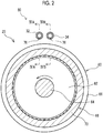
- FIGS. 2 and 3 are views illustrating the configuration of a cooling structure 80 of the second rotary electric machine 20 related to the present embodiment.
- a cross-section including a rotational axis, especially, a cross-section of a stator is illustrated in FIG. 2
- a section orthogonal to a rotational axis of the second rotary electric machine 20 is illustrated in FIG. 3 .
- FIGS. 4A and 4B are views illustrating a discharge state of the oil by the cooling structure 80
- FIG. 4A is a partial sectional view taken along line IVA-IVA illustrated in FIG. 2
- FIG. 4B is a partial sectional view taken along line IVB-IVB illustrated in FIG. 2 .
- the second rotary electric machine 20 has a cylindrical or annular stator 60, and a columnar or disk-shaped rotor 62 that is disposed coaxially with the cylindrical shape of the stator 60.
- a rotating shaft 64 passes through the center of the rotor 62.
- the rotating shaft 64 functions as an output shaft for outputting a rotational force to the outside when the second rotary electric machine 20 operates as an electric motor drive.
- the rotating shaft 64 functions as an input shaft for inputting a rotational force from the outside when the second rotary electric machine 20 operates as the generator.
- the second rotary electric machine 20 is used, for example, in a state where the rotating shaft 64 is disposed sideways as illustrated.
- the stator 60 includes a stator core 66 in which irregularities are alternately arranged in a circumferential direction at an inner periphery.
- a coil conducting wire is received in a recessed portion provided at the inner periphery of the stator core 66, and a coil 68 is formed such that the coil conducting wire winds a protruding portion.
- a rotating magnetic field is formed in a space inside the stator 60 by supplying electric power to the coil 68.
- the coil 68 is wound around the stator core 66 such that a rotating magnetic field is formed when electric power is supplied.
- the protruding portion of the inner periphery of the stator core 66 is also referred to as teeth and the recessed portion is also referred to as slots.
- a plurality of coil conducting wires is complicatedly bundled.
- a portion in which the coil conducting wires are bundled is a coil end 70.
- the coil conducting wires are complicatedly bundled as described above, and a portion having a gap is present between the coil conducting wires.
- the section of the coil end has a rectangular annular shape as a whole, and is located adjacent to a cylindrical end surface of the stator core 66.
- FIG. 2 in the coil end 70, bundled individual coil conducting wires are not drawn, and are illustrated in a simplified annular shape.
- the rotor 62 has a cylindrical shape as a whole, and is disposed with a slight gap from an inner periphery, especially, teeth tips of the stator 60.
- a permanent magnet is buried near an outer peripheral surface or an outer peripheral surface of the rotor so as to rotate due to the interaction with the rotating magnetic field formed by the stator 60.
- Portions having different reluctances in the circumferential direction of the rotor 62 can be provided, and the rotor 62 can be rotated due to an interaction between the portions having different reluctances and the rotating magnetic field.
- the rotating shaft 64 is fixed to the rotor so as to rotate integrally with the rotor 62.
- cooling structure 80 of the present embodiment as described above, two systems are provided as the cooling paths that deliver the oil to be used for cooling the second rotary electric machine 20. That is, in the cooling structure 80 of the present embodiment, the second rotary electric machine 20 including the coil end 70 is cooled by supplying the oil from the first supply pipe 32 and the second supply pipe 34 disposed in parallel above the second rotary electric machine 20.
- the structure of the first supply pipe 32 and a discharge state of the oil by the first supply pipe 32 are illustrated in FIG. 4A .
- the first supply pipe 32 is disposed in parallel with the rotating shaft 64 above the stator core 66.
- the first supply pipe 32 has a tubular, for example, cylindrical, side wall 72, and an end wall 74 provided so as to close one end of the tube.
- a discharge hole 76 is provided in a surface of the side wall 72 that faces the second rotary electric machine 20. In the present embodiment, three discharge holes 76 are provided in a length direction of the first supply pipe 32.
- Two of the three discharge holes 76 are disposed at positions that face the coil end 70 on the both sides of the stator core 66, and the remaining one thereof is disposed at a position that faces an outer periphery of the stator core 66. Accordingly, as indicated by arrows in FIG. 4A , the oil delivered into the first supply pipe 32 flows through the first supply pipe 32 toward the end wall 74 from an open end (a right side of FIG. 4A ) of the tube, and is discharged toward the second rotary electric machine 20 from the individual discharge holes 76.
- cooling structure 90 of the related art illustrated in FIG. 5 will be described.
- supply of the refrigerant to the second rotary electric machine 20 is independently performed by the first supply pipe 32 disposed above the second rotary electric machine 20.
- the oil pumped by the mechanical oil pump 42 is delivered into the first supply pipe 32, and is discharged from the individual discharge holes 76.
- the positions of the individual discharge holes 76 are determined, for example, such that oil is discharged to a cooling-desired region, such as the coil end 70 or a region where a cooling effect is relatively high, while taking into consideration a discharge direction of the oil from the discharge holes 76.
- the above-described problems are not limited to the mechanical oil pump 42, and may occur even in a case where a refrigerant for cooling a rotary electric machine is pumped to one supply pipe by an electric oil pump in a cooling structure that supplies the refrigerant by the one supply pipe.
- a control device of the electric oil pump may increase the flow rate of the oil pumped from the electric oil pump for the purpose of further enhancing the cooling performance of the rotary electric machine.
- the cooling structure 90 illustrated in FIG. 5 a possibility that the flow rate and the pressure of the oil flowing through the first supply pipe 32 increase, the deviation of the discharge direction of the oil from the discharge holes 76 with respect to an assumed direction occurs, and desired cooling performance is not sufficiently obtained is considered.
- the second supply pipe 34 configured such that the direction of the oil flowing therethrough faces the direction of the oil flowing through the first supply pipe 32 is provided as a supply pipe that supplies the refrigerant for cooling the second rotary electric machine 20.
- the structure of the second supply pipe 34 that constitute the cooling structure 80 and the discharge state of the oil is illustrated in FIG. 4B .
- the second supply pipe 34 has the same configuration as the first supply pipe 32, the direction in which the oil flows is a direction that faces the first supply pipe 32. That is, the second supply pipe 34 has a tubular, for example, cylindrical side wall 72, and an end wall 74 provided so as to close one end of the tube. However, the end wall 74 is provided on a side (a right side of FIG. 4B ) opposite to the first supply pipe 32 in the length direction.
- Three discharge holes 76 are provided in the length direction in a surface of the side wall 72 of the second supply pipe 34 that faces the second rotary electric machine 20.
- Two of the three discharge holes 76 are disposed at positions that face the coil end 70 on the both sides of the stator core 66, and the remaining one thereof is disposed at a position that faces the outer periphery of the stator core 66. Accordingly, as indicated by arrows in FIG. 4B , the oil delivered into the second supply pipe 34 flows through the second supply pipe 34 toward the end wall 74 from an open end (a left side of FIG. 4B ) of the tube, and is discharged toward the second rotary electric machine 20 from the individual discharge holes 76.
- the cooling structure 80 of the present embodiment a case where the flow rate and pressure of the oil, which is pumped by the mechanical oil pump 42 and flows through the first supply pipe 32, increases, and the discharge direction of the oil from the individual discharge holes 76 deviates to the end wall 74 side is considered.
- the discharge direction of the oil from the individual discharge holes 76 of the second supply pipe 34 is displaced to the opposite side in accordance with the deviation of the discharge direction of the oil from the individual discharge holes 76 of the first supply pipe 32.
- the discharge direction of the oil is changed from a discharge direction a' of the oil illustrated in FIG. 4B to a discharge direction b' on the end wall 74 side.
- the deviation of the oil discharge direction in the first supply pipe 32 and the deviation of the oil discharge direction in the second supply pipe 34 can be cancelled off, and the oil can be discharged within a desired range.
- the cooling structure 80 related to the present embodiment even in a case where the flow rate and the pressure of the oil flowing through the first supply pipe 32 or the second supply pipe 34 increase as compared to the cooling structure 90 using the first supply pipe 32 independently, the oil that cools the second rotary electric machine 20 can be discharged to a region having a relatively high cooling effect or to a region where cooling is desired.
- the supply stability of the refrigerant can be further improved, the cooling performance of the second rotary electric machine 20 can be further improved, and improvements in the power performance of the hybrid vehicle can be realized.
- the pumping of the oil to the first supply pipe 32 is performed using the mechanical oil pump 42.
- the pumping of the oil to the second supply pipe 34 is performed using the electric oil pump 44, and the respective oil pumps are different from each other.
- the flow rate or the pressure of the oil delivered to the other cooling path can be independently controlled in a case where the flow rate or the pressure of the oil delivered to one cooling path increases. Accordingly, the discharge range of the oil to the second rotary electric machine 20 can be adjusted to a more desirable range from a viewpoint of the cooling performance. As a result, improvements in the cooling performance of the second rotary electric machine 20 can be realized.
- the pumping of the oil to the first supply pipe 32 and the second supply pipe 34 by the oil pumps that are independent from each other are shown.
- the pumping of the oil to the first supply pipe 32 and the second supply pipe 34 may be performed by one oil pump.
- the pumping of the oil to the first supply pipe 32 and the second supply pipe 34 is performed by the one oil pump, it is considered that increases in the flow rates or the pressures of the oil in both the supply pipes by the oil pump are almost the same, and the deviations of the discharge directions of the oil from the discharge holes 76 are also almost the same.
- the cooling structure 80 of the present embodiment since the directions of the oil flowing through the first supply pipe 32 and the second supply pipe 34 face each other, the deviation of the discharge range of the oil to the second rotary electric machine 20 is averaged consequently. As a result, as compared to the cooling structure using the first supply pipe 32 independently, improvements in the cooling performance of the second rotary electric machine 20 in a case where the flow rate and the pressure of the oil are increased can be realized.
- the oil is pumped to one of the first supply pipe 32 and the second supply pipe 34 using the mechanical oil pump 42, and the oil is pumped to the other using the electric oil pump 44.
- the cooling performance of the rotary electric machine can be further improved by increasing the discharge amount of the refrigerant to the rotary electric machine with the mechanical oil pump 42 in which the pumping amount of the oil increases in accordance with load amount under the condition that a high load is applied to the rotary electric machine, and the discharge range of the refrigerant to the rotary electric machine can be made optimal from the viewpoint of the cooling performance by appropriately adjusting the discharge direction of the refrigerant pumped from the electric oil pump 44 with the electric oil pump 44 in which the pumping amount of the oil does not depend on the load amount.
- the oil is pumped to both of the MG1 supply pipe 36 for supplying the oil to the first rotary electric machine 18 used as the generator and the first supply pipe 32 for supplying the oil to the second rotary electric machine 20 used as the motor by the mechanical oil pump 42.
- the first rotary electric machine 18 can supply the oil for cooling the first rotary electric machine 18 with an amount according to the load amount of the first rotary electric machine 18 by supplying the oil to the MG1 supply pipe 36 with the mechanical oil pump 42 in which the pumping amount of the refrigerant increases and the temperature also rises, in accordance with the driving of the engine, and similarly, the load amount increases in accordance with the driving of the engine.
- the first supply passage 28 that supplies the refrigerant to the first supply pipe 32 includes the cooler 50, and the refrigerant to be delivered to the first supply pipe 32 is cooled by the cooler 50.
- the second supply passage 30 that supplies the refrigerant to the second supply pipe 34 includes the water-cooling cooler 52, and the refrigerant to be delivered to the second supply pipe 34 is cooled by the water-cooling cooler 52.
- the refrigerant delivered to one of the first supply pipe and the second supply pipe is cooled by the cooler 50, and the refrigerant delivered to the other is cooled by the water-cooling cooler 52.
- the invention may be applied to electric automobiles, such as a plug-in hybrid vehicle (PHV) and an electric vehicle (EV), in which rotary electric machines are provided as the prime movers.
- HV hybrid vehicle
- EV electric vehicle
- first supply pipe 32 and one second supply pipe 34 are disposed.
- first supply pipe 32 and the second supply pipe 34 may be constituted of two or more pipes.
Abstract
Description
- The present invention relates to a cooling structure that cools a rotary electric machine.
- Electric motor drives that convert electrical energy into rotational kinetic energy, generators that convert rotational kinetic energy into electrical energy, and electric devices that function as both an electric motor drive and a generator are known. In the following, the above-described electric devices are described as rotary electric machines.
- A rotary electric machine has two members that are coaxially disposed and rotated relative to each other. Usually, one member is fixed and the other member is rotated. A coil is disposed at the fixed member (stator), and a magnetic field that is rotated by supplying electric power to the coil is formed. The other member (rotor) is rotated due to an interaction with the above-described magnetic field.
- Electric vehicles, such as a hybrid vehicle (HV), a plug-in hybrid vehicle (PHV) including a rotary electric machine as a prime mover together with an internal combustion engine, and an electric automobile (EV), are known. As a power unit for the above-described electric vehicles, one having a configuration in which a rotary electric machine is integrated with a transaxle or a transmission has been put to practical use. In the power unit for the electric vehicles, the rotary electric machine is housed within a case, such as the transaxle, and direct cooling with ambient air cannot be expected. Thus, lubricating oil included in the transaxle or the like or a hydraulic fluid for device control is supplied to the rotary electric machine to cool the rotary electric machine.
- For example, Japanese Unexamined Patent Application Publication No.
2009-96326 JP 2009-96326 A - In addition to high outputs and downsizing of the rotary electric machines, in the rotary electric machines of the electric vehicles including EV and PHV that are under development, the load of the rotary electric machines tends to become high as compared to HV of the related art. For that reason, in the rotary electric machines for the electric vehicles, further improvements in cooling performance are desired.
- The invention provides a cooling structure for a rotary electric machine capable of further improving the supply stability of a refrigerant and further improving the cooling performance of the rotary electric machine, and the cooling structure for the rotary electric machine includes a supply pipe of the rotary electric machine that supplies the refrigerant from above.
- An aspect of the invention relates to a cooling structure for a rotary electric machine including a first supply pipe, a second supply, and a pump. The first supply pipe is disposed vertically above a rotary electric machine and has a discharge hole through which a refrigerant is discharged toward the rotary electric machine. The second supply pipe is disposed in parallel with the first supply pipe vertically above the rotary electric machine and has a discharge hole through which the refrigerant is discharged toward the rotary electric machine. The pump is configured to deliver the refrigerant to the first supply pipe and the second supply pipe such that a direction of the refrigerant flowing through the first supply pipe and a direction of the refrigerant flowing through the second supply pipe are opposite to each other.
- In the cooling structure according to the aspect of the invention, the pump may include a first pump that delivers the refrigerant to the first supply pipe, and a second pump that delivers the refrigerant to the second supply pipe.
- In the cooling structure according to the aspect of the invention, the first pump may be a mechanical oil pump; and the second pump may be an electric oil pump.
- By virtue of the above-described configuration, in the cooling structure for the rotary electric machine including the supply pipe of the rotary electric machine that supplies the refrigerant from above, the supply stability of the refrigerant can be further improved, and the cooling performance of the rotary electric machine can be further improved.
- According to the aspect of the invention, in a case where the flow rate or the pressure of the refrigerant delivered to one of the first supply pipe and the second supply pipe increases, the flow rate or the pressure of the refrigerant delivered to the other can be independently controlled. Accordingly, the discharge range of the refrigerant to the rotary electric machine can be adjusted to a more desirable range from a viewpoint of the cooling performance, and improvements in the cooling performance of the rotary electric machine can be realized.
- According to the aspect of the invention, the refrigerant is pumped to one of the first supply pipe and the second supply pipe using the mechanical oil pump, and the refrigerant is pumped to the other using the electric oil pump. As a result, the cooling performance of the rotary electric machine can be further improved by increasing the discharge amount of the refrigerant using the mechanical oil pump, in which the pumping amount of the refrigerant increases or decreases in accordance with load amount under the condition that a high load is applied to the rotary electric machine, for one supply pipe, and the discharge range of the refrigerant to the rotary electric machine can be made optimal from the viewpoint of the cooling performance by appropriately adjusting the discharge direction of the refrigerant using the electric oil pump, which can adjust the pumping amount of the refrigerant without depending on the load amount, for the other supply pipe.
- Features, advantages, and technical and industrial significance of exemplary embodiments of the invention will be described below with reference to the accompanying drawings, in which like numerals denote like elements, and wherein:
-
FIG. 1 is a view illustrating the configuration of a vehicle control system in the present embodiment; -
FIG. 2 is a view illustrating the configuration of a rotary electric machine and a cooling structure therefor in the present embodiment; -
FIG. 3 is a view illustrating the configuration of the rotary electric machine and the cooling structure therefor in the present embodiment; -
FIG. 4A is a view illustrating a discharge state of a refrigerant by the cooling structure for the rotary electric machine of the present embodiment; -
FIG. 4B is a view illustrating a discharge state of the refrigerant by the cooling structure for the rotary electric machine of the present embodiment; and -
FIG. 5 is a view illustrating the configuration of a rotary electric machine and a cooling structure therefor in the related art. - Hereinafter, embodiments related to the invention will be described in detail with reference to the drawings. In the following, a hybrid vehicle on which an internal combustion engine, two rotary electric machines, a mechanical oil pump, an electric oil pump, and the like are mounted will be described as a vehicle. This is merely an example for description.
-
FIG. 1 is a view illustrating the configuration of avehicle control system 10 regarding a hybrid vehicle. Thevehicle control system 10 includes apower unit 14 mounted on the hybrid vehicle. - The
power unit 14 includes an engine (not illustrated) that is an internal combustion engine, a first rotaryelectric machine 18 illustrated as MG1, a second rotaryelectric machine 20 illustrated as MG2, and apower transmission mechanism 16 provided between the first rotaryelectric machine 18 and the second rotaryelectric machine 20. - The first rotary
electric machine 18 and the second rotaryelectric machine 20 are motor generators (MG) mounted on the vehicle, and function as motors when electric power is supplied. The first rotaryelectric machine 18 and the second rotaryelectric machine 20 are rotary electric machines that are three-phase synchronous type rotary electric machines that function as generators when being braked or driven by the engine. Here, one of the first rotaryelectric machine 18 and the second rotaryelectric machine 20 is mainly used as a generator for charge a battery (not illustrated) and the other thereof is mainly used as a drive motor for vehicle running. - For example, the first rotary
electric machine 18 is used as a generator that is driven by the engine to generate electric power and supplies the generated electric power to the battery. The second rotaryelectric machine 20 is used for vehicle running, and receives supply of the electric power from the battery to function as a motor to drive vehicle axles of the vehicle, at the time of powering. The second rotaryelectric machine 20 can function as a generator to regenerate braking energy to supply the braking energy to the battery, at the time of braking. In the following, a case where the first rotaryelectric machine 18 is used as the generator and the second rotaryelectric machine 20 is used as the motor will be described. - The
power transmission mechanism 16 is a mechanism that has a function of distributing the power to be supplied to the hybrid vehicle between the output of the engine and the output the first rotaryelectric machine 18 and the second rotaryelectric machine 20. As thepower transmission mechanism 16 as described above, an output shaft of the engine, output shafts of the first rotaryelectric machine 18 and the second rotaryelectric machine 20, and planetary gear mechanisms that are respectively connected to output shafts to the vehicle axles can be used. The output shaft of the engine connects thepower transmission mechanism 16 and the engine, is connected to a drive shaft of amechanical oil pump 42 via a connection shaft, and is used for driving themechanical oil pump 42. - The charging to a chargeable battery (power source) is performed, for example, by driving the first rotary
electric machine 18 with the engine and by supplying the electric power generated by the first rotaryelectric machine 18. The battery can be constituted of a lithium ion battery pack having a terminal voltage of about 300 V to about 200 V. The battery pack is one in which a plurality of batteries having a terminal voltage of 1 V to several V, which are referred to as single batteries or battery cells, are combined to obtain the above-described predetermined terminal voltage. As the batteries, large-capacity capacitors can be used in addition to secondary batteries, such as the lithium ion battery pack and a nickel hydrogen battery pack. - A
case body 24 is a housing that includes thepower transmission mechanism 16, the first rotaryelectric machine 18, and the second rotaryelectric machine 20 therein, and is also referred to as a transaxle. Oil for performing lubrication of movable parts of thepower transmission mechanism 16, the first rotaryelectric machine 18, and the second rotaryelectric machine 20 and cooling of thepower transmission mechanism 16, the first rotaryelectric machine 18, and the second rotaryelectric machine 20 is stored in an internal space of thecase body 24. As the oil also having a function of a refrigerant, for example, lubricating oil referred to as an automatic transmission fluid (ATF) can be used. - A
cooling system 12 has afirst supply passage 28 including themechanical oil pump 42 and asecond supply passage 30 including anelectric oil pump 44, as a cooling circuit that circulates and supplies the oil to be used for cooling the first rotaryelectric machine 18 and the second rotaryelectric machine 20. Themechanical oil pump 42 and theelectric oil pump 44 respectively circulate and supply the oil serving as the refrigerant into the internal space of thecase body 24. - The
mechanical oil pump 42 and theelectric oil pump 44 are configured to suction the oil via astrainer 58 from an oil pan (not illustrated) in which the oil is stored. Specifically, arefrigerant intake passage 38 is connected to thestrainer 58 provided on a lower side of thecase body 24, and therefrigerant intake passage 38 branches to anelectric oil pump 44 side and amechanical oil pump 42 side downstream of thestrainer 58. That is, themechanical oil pump 42 and theelectric oil pump 44 are connected in parallel to thestrainer 58. - The
first supply passage 28 is configured to include themechanical oil pump 42, an air-cooling type oil cooler (hereinafter referred to as a "cooler") 50, afirst check valve 54, anMG1 supply pipe 36, and afirst supply pipe 32. - The
mechanical oil pump 42 is a mechanical refrigerant pump in which the drive shaft is connected to the output shaft of the engine, and is driven when the engine operates. That is, when the vehicle runs with engine power, themechanical oil pump 42 delivers the oil from a delivery port. The oil delivered from themechanical oil pump 42 while it is supplied to thepower transmission mechanism 16 and the first rotaryelectric machine 18 to function as the lubricating oil, and functions as the refrigerant of the first rotaryelectric machine 18 and the second rotaryelectric machine 20 via thefirst supply passage 28. Themechanical oil pump 42 starts to be driven with the startup of the engine, and ends being driven when the engine stops. - The
first check valve 54 is provided between themechanical oil pump 42 and the cooler 50, and has a function of restraining a backflow of the oil on the delivery port side of themechanical oil pump 42. The oil delivered by themechanical oil pump 42 passes through thefirst check valve 54, and is pumped to the cooler 50. - A branch point P is a position where a flow passage branches to the cooler 50 side and first rotary
electric machine 18 side between themechanical oil pump 42 and the cooler 50. The oil delivered from themechanical oil pump 42 is supplied to the first rotaryelectric machine 18 and thepower transmission mechanism 16 without passing through the cooler 50 when being pumped to the first rotaryelectric machine 18 andpower transmission mechanism 16 side at the branch point P. On the other hand, the oil pumped to the cooler 50 side at the branch point P flows into the cooler 50. - The cooler 50 is a heat exchanger that performs heat exchange between the oil and air (for example, ambient air of the vehicle), and has cooling performance superior to the water-cooling
cooler 52. Since the cooler 50 is provided outside thecase body 24, the oil pumped into thefirst supply passage 28 first flows outside thecase body 24, and then returns to the inside of thecase body 24 again. - The
first supply passage 28 is provided with tworelief valves 40 that adjust the hydraulic pressure within thefirst supply passage 28. Eachrelief valve 40 has a supply port connected to thefirst supply passage 28 and has a discharge port opening toward the inside of thecase body 24. For example, the relief pressures of the tworelief valves 40 are set to different magnitudes. The oil within thefirst supply passage 28 is configured to be supplied from eachrelief valve 40 to the inside of thecase body 24 at the time of overpressure. - The
first supply passage 28 branches to theMG1 supply pipe 36 side that supplies the refrigerant to the first rotaryelectric machine 18, and thefirst supply pipe 32 side that supplies the refrigerant to the second rotaryelectric machine 20, at a branch point Q downstream of the cooler 50. TheMG1 supply pipe 36 is a flow passage provided inside thecase body 24, is provided above the first rotaryelectric machine 18, and discharge the refrigerant to the first rotaryelectric machine 18. Thefirst supply pipe 32 is a flow passage provided inside thecase body 24, is provided above the second rotaryelectric machine 20, and discharge the refrigerant to the second rotaryelectric machine 20. Accordingly, the oil air-cooled by the cooler 50 is supplied to each of the first rotaryelectric machine 18 and the second rotaryelectric machine 20. - The
second supply passage 30 is configured to include theelectric oil pump 44, a water cooling type oil cooler (hereinafter referred to as a "water-cooling cooler") 52, asecond check valve 56, and asecond supply pipe 34. - The
electric oil pump 44 is an electric refrigerant pump that is driven by anelectric motor 48 and is controlled by acontrol device 46. Thecontrol device 46 is constituted of a well-known electronic control device that can control theelectric oil pump 44, and controls driving of theelectric oil pump 44 by controlling theelectric motor 48. Thecontrol device 46 can be constituted of a computer suitable for mounting to the hybrid vehicle. Thecontrol device 46 may be a portion of another control device to be mounted on the hybrid vehicle, for example, a control device that controls individual elements of thecooling system 12 or an integrated control device that performs control of the overall vehicle. - The water-cooling cooler 52 is a heat exchanger that performs heat exchange between the oil and a coolant. Since the water-cooling cooler 52 is provided outside the
case body 24, the oil pumped into thesecond supply passage 30 first flows outside thecase body 24, and then returns to the inside of thecase body 24 again. - The
second check valve 56 is provided between the water-cooling cooler 52 and thesecond supply pipe 34, and has a function of restraining a backflow of the oil on the delivery port side of theelectric oil pump 44. The oil delivered by theelectric oil pump 44 passes through the water-cooling cooler 52 and thesecond check valve 56, and is pumped to thesecond supply pipe 34. - The
second supply pipe 34 is a flow passage provided inside thecase body 24, is provided above the second rotaryelectric machine 20, and discharge the refrigerant to the second rotaryelectric machine 20. Accordingly, the oil water-cooled by the water-cooling cooler 52 is supplied to the second rotaryelectric machine 20. - In order to effectively cool the second rotary
electric machine 20, thecooling system 12 related to the present embodiment can pump the oil (refrigerant) cooled by the cooler 50 and the water-cooling cooler 52 having different cooling performances, in different paths, and supply the oil from thefirst supply pipe 32 and thesecond supply pipe 34, which are different from each other, to the second rotaryelectric machine 20. A plurality of cooling paths reaching the second rotaryelectric machine 20 is formed in thecooling system 12 as described above. - Although both the
first supply passage 28 and thesecond supply passage 30 can be constituted of tubular members, one or both thereof may be flow passages formed by making holes in thecase body 24. - Hereinafter, a structure that cools the second rotary
electric machine 20 will be described in detail, referring to the drawings.FIGS. 2 and3 are views illustrating the configuration of acooling structure 80 of the second rotaryelectric machine 20 related to the present embodiment. A cross-section including a rotational axis, especially, a cross-section of a stator is illustrated inFIG. 2 , and a section orthogonal to a rotational axis of the second rotaryelectric machine 20 is illustrated inFIG. 3 .FIGS. 4A and 4B are views illustrating a discharge state of the oil by the coolingstructure 80,FIG. 4A is a partial sectional view taken along line IVA-IVA illustrated inFIG. 2 , andFIG. 4B is a partial sectional view taken along line IVB-IVB illustrated inFIG. 2 . - The second rotary
electric machine 20 has a cylindrical orannular stator 60, and a columnar or disk-shapedrotor 62 that is disposed coaxially with the cylindrical shape of thestator 60. A rotatingshaft 64 passes through the center of therotor 62. The rotatingshaft 64 functions as an output shaft for outputting a rotational force to the outside when the second rotaryelectric machine 20 operates as an electric motor drive. The rotatingshaft 64 functions as an input shaft for inputting a rotational force from the outside when the second rotaryelectric machine 20 operates as the generator. The second rotaryelectric machine 20 is used, for example, in a state where the rotatingshaft 64 is disposed sideways as illustrated. - The
stator 60 includes astator core 66 in which irregularities are alternately arranged in a circumferential direction at an inner periphery. A coil conducting wire is received in a recessed portion provided at the inner periphery of thestator core 66, and acoil 68 is formed such that the coil conducting wire winds a protruding portion. A rotating magnetic field is formed in a space inside thestator 60 by supplying electric power to thecoil 68. In other words, thecoil 68 is wound around thestator core 66 such that a rotating magnetic field is formed when electric power is supplied. - The protruding portion of the inner periphery of the
stator core 66 is also referred to as teeth and the recessed portion is also referred to as slots. In regions adjacent to end surfaces of thestator core 66, a plurality of coil conducting wires is complicatedly bundled. A portion in which the coil conducting wires are bundled is acoil end 70. In thecoil end 70, the coil conducting wires are complicatedly bundled as described above, and a portion having a gap is present between the coil conducting wires. However, the section of the coil end has a rectangular annular shape as a whole, and is located adjacent to a cylindrical end surface of thestator core 66. InFIG. 2 , in thecoil end 70, bundled individual coil conducting wires are not drawn, and are illustrated in a simplified annular shape. - The
rotor 62 has a cylindrical shape as a whole, and is disposed with a slight gap from an inner periphery, especially, teeth tips of thestator 60. In therotor 62, for example, a permanent magnet is buried near an outer peripheral surface or an outer peripheral surface of the rotor so as to rotate due to the interaction with the rotating magnetic field formed by thestator 60. Portions having different reluctances in the circumferential direction of therotor 62 can be provided, and therotor 62 can be rotated due to an interaction between the portions having different reluctances and the rotating magnetic field. The rotatingshaft 64 is fixed to the rotor so as to rotate integrally with therotor 62. - Here, although the heat generated in the coil conducting wires within the slots flows to the surrounding
stator core 66, there is no good conductor for heat around thecoil end 70. Therefore, temperature tends to rise. For this reason, efficient cooling of thecoil end 70 is desired. Generally, since liquid has thermal conductivity better than gas, efficient cooling can be expected in the cooling by the oil. By hanging oil from above and taking heat when the oil flows through thecoil end 70, the amount of the oil used can be reduced compared to a case where thecoil end 70 is immersed in the oil. - In the
cooling structure 80 of the present embodiment, as described above, two systems are provided as the cooling paths that deliver the oil to be used for cooling the second rotaryelectric machine 20. That is, in thecooling structure 80 of the present embodiment, the second rotaryelectric machine 20 including thecoil end 70 is cooled by supplying the oil from thefirst supply pipe 32 and thesecond supply pipe 34 disposed in parallel above the second rotaryelectric machine 20. - The structure of the
first supply pipe 32 and a discharge state of the oil by thefirst supply pipe 32 are illustrated inFIG. 4A . Thefirst supply pipe 32 is disposed in parallel with the rotatingshaft 64 above thestator core 66. Thefirst supply pipe 32 has a tubular, for example, cylindrical,side wall 72, and anend wall 74 provided so as to close one end of the tube. Adischarge hole 76 is provided in a surface of theside wall 72 that faces the second rotaryelectric machine 20. In the present embodiment, threedischarge holes 76 are provided in a length direction of thefirst supply pipe 32. Two of the threedischarge holes 76 are disposed at positions that face thecoil end 70 on the both sides of thestator core 66, and the remaining one thereof is disposed at a position that faces an outer periphery of thestator core 66. Accordingly, as indicated by arrows inFIG. 4A , the oil delivered into thefirst supply pipe 32 flows through thefirst supply pipe 32 toward theend wall 74 from an open end (a right side ofFIG. 4A ) of the tube, and is discharged toward the second rotaryelectric machine 20 from the individual discharge holes 76. - Here, a cooling
structure 90 of the related art illustrated inFIG. 5 will be described. In thecooling structure 90 illustrated inFIG. 5 , supply of the refrigerant to the second rotaryelectric machine 20 is independently performed by thefirst supply pipe 32 disposed above the second rotaryelectric machine 20. As described above, the oil pumped by themechanical oil pump 42 is delivered into thefirst supply pipe 32, and is discharged from the individual discharge holes 76. The positions of the individual discharge holes 76 are determined, for example, such that oil is discharged to a cooling-desired region, such as thecoil end 70 or a region where a cooling effect is relatively high, while taking into consideration a discharge direction of the oil from the discharge holes 76. However, since the drive shaft of themechanical oil pump 42 is connected to the output shaft of the engine, when the engine operates at high-speed rotation, the flow rate and pressure of the oil to be pumped may increase, and the discharge direction of the oil may deviate in a discharge direction b on theend wall 74 side from a discharge direction a (for example, vertical direction) inFIG. 4A . As a result, in thecooling structure 90 of the related art in which the supply of the refrigerant is independently performed byfirst supply pipe 32, there is a possibility that the refrigerant is not supplied with an assumed amount or within an assumed range, and the desired cooling performance of the second rotaryelectric machine 20 is not sufficiently obtained. - The above-described problems are not limited to the
mechanical oil pump 42, and may occur even in a case where a refrigerant for cooling a rotary electric machine is pumped to one supply pipe by an electric oil pump in a cooling structure that supplies the refrigerant by the one supply pipe. For example, in a case where the output of the rotary electric machine increases or in a case where the temperature of the rotary electric machine rises, a control device of the electric oil pump may increase the flow rate of the oil pumped from the electric oil pump for the purpose of further enhancing the cooling performance of the rotary electric machine. As a result, in the example of the coolingstructure 90 illustrated inFIG. 5 , a possibility that the flow rate and the pressure of the oil flowing through thefirst supply pipe 32 increase, the deviation of the discharge direction of the oil from the discharge holes 76 with respect to an assumed direction occurs, and desired cooling performance is not sufficiently obtained is considered. - In the
cooling structure 80 of the present embodiment, as illustrated inFIG. 2 , in addition to thefirst supply pipe 32, thesecond supply pipe 34 configured such that the direction of the oil flowing therethrough faces the direction of the oil flowing through thefirst supply pipe 32 is provided as a supply pipe that supplies the refrigerant for cooling the second rotaryelectric machine 20. - The structure of the
second supply pipe 34 that constitute the coolingstructure 80 and the discharge state of the oil is illustrated inFIG. 4B . Although thesecond supply pipe 34 has the same configuration as thefirst supply pipe 32, the direction in which the oil flows is a direction that faces thefirst supply pipe 32. That is, thesecond supply pipe 34 has a tubular, for example,cylindrical side wall 72, and anend wall 74 provided so as to close one end of the tube. However, theend wall 74 is provided on a side (a right side ofFIG. 4B ) opposite to thefirst supply pipe 32 in the length direction. Three discharge holes 76 are provided in the length direction in a surface of theside wall 72 of thesecond supply pipe 34 that faces the second rotaryelectric machine 20. Two of the threedischarge holes 76 are disposed at positions that face thecoil end 70 on the both sides of thestator core 66, and the remaining one thereof is disposed at a position that faces the outer periphery of thestator core 66. Accordingly, as indicated by arrows inFIG. 4B , the oil delivered into thesecond supply pipe 34 flows through thesecond supply pipe 34 toward theend wall 74 from an open end (a left side ofFIG. 4B ) of the tube, and is discharged toward the second rotaryelectric machine 20 from the individual discharge holes 76. - In the
cooling structure 80 of the present embodiment, a case where the flow rate and pressure of the oil, which is pumped by themechanical oil pump 42 and flows through thefirst supply pipe 32, increases, and the discharge direction of the oil from the individual discharge holes 76 deviates to theend wall 74 side is considered. In this case, in thecooling structure 80 of the present embodiment, the discharge direction of the oil from the individual discharge holes 76 of thesecond supply pipe 34 is displaced to the opposite side in accordance with the deviation of the discharge direction of the oil from the individual discharge holes 76 of thefirst supply pipe 32. For example, by controlling the driving of theelectric oil pump 44 with thecontrol device 46 to increase the flow rate and the pressure of the oil flowing thesecond supply pipe 34, the discharge direction of the oil is changed from a discharge direction a' of the oil illustrated inFIG. 4B to a discharge direction b' on theend wall 74 side. As a result, the deviation of the oil discharge direction in thefirst supply pipe 32 and the deviation of the oil discharge direction in thesecond supply pipe 34 can be cancelled off, and the oil can be discharged within a desired range. As described above, in thecooling structure 80 related to the present embodiment, even in a case where the flow rate and the pressure of the oil flowing through thefirst supply pipe 32 or thesecond supply pipe 34 increase as compared to thecooling structure 90 using thefirst supply pipe 32 independently, the oil that cools the second rotaryelectric machine 20 can be discharged to a region having a relatively high cooling effect or to a region where cooling is desired. As a result, the supply stability of the refrigerant can be further improved, the cooling performance of the second rotaryelectric machine 20 can be further improved, and improvements in the power performance of the hybrid vehicle can be realized. - As long as the directions of the oil that flows through the supply pipes are the same direction even when the supply pipes for supplying the refrigerant to the rotary electric machines are provided, the discharge direction of the oil from the discharge hole deviates when the flow rate and the pressure of the oil flowing through the supply pipes increase. Accordingly, the above-described problems that the cooling performance is not satisfactory may occur still.
- In the
cooling structure 80 of the present embodiment, the pumping of the oil to thefirst supply pipe 32 is performed using themechanical oil pump 42. On the other hand, the pumping of the oil to thesecond supply pipe 34 is performed using theelectric oil pump 44, and the respective oil pumps are different from each other. When the different oil pumps are used in the individual cooling paths as described above, the flow rate or the pressure of the oil delivered to the other cooling path can be independently controlled in a case where the flow rate or the pressure of the oil delivered to one cooling path increases. Accordingly, the discharge range of the oil to the second rotaryelectric machine 20 can be adjusted to a more desirable range from a viewpoint of the cooling performance. As a result, improvements in the cooling performance of the second rotaryelectric machine 20 can be realized. - In the above description, an aspect in which the pumping of the oil to the
first supply pipe 32 and thesecond supply pipe 34 by the oil pumps that are independent from each other are shown. However, the pumping of the oil to thefirst supply pipe 32 and thesecond supply pipe 34 may be performed by one oil pump. In a case where the pumping of the oil to thefirst supply pipe 32 and thesecond supply pipe 34 is performed by the one oil pump, it is considered that increases in the flow rates or the pressures of the oil in both the supply pipes by the oil pump are almost the same, and the deviations of the discharge directions of the oil from the discharge holes 76 are also almost the same. In thecooling structure 80 of the present embodiment, since the directions of the oil flowing through thefirst supply pipe 32 and thesecond supply pipe 34 face each other, the deviation of the discharge range of the oil to the second rotaryelectric machine 20 is averaged consequently. As a result, as compared to the cooling structure using thefirst supply pipe 32 independently, improvements in the cooling performance of the second rotaryelectric machine 20 in a case where the flow rate and the pressure of the oil are increased can be realized. - In the present embodiment, the oil is pumped to one of the
first supply pipe 32 and thesecond supply pipe 34 using themechanical oil pump 42, and the oil is pumped to the other using theelectric oil pump 44. As a result, the cooling performance of the rotary electric machine can be further improved by increasing the discharge amount of the refrigerant to the rotary electric machine with themechanical oil pump 42 in which the pumping amount of the oil increases in accordance with load amount under the condition that a high load is applied to the rotary electric machine, and the discharge range of the refrigerant to the rotary electric machine can be made optimal from the viewpoint of the cooling performance by appropriately adjusting the discharge direction of the refrigerant pumped from theelectric oil pump 44 with theelectric oil pump 44 in which the pumping amount of the oil does not depend on the load amount. - In the present embodiment, the oil is pumped to both of the
MG1 supply pipe 36 for supplying the oil to the first rotaryelectric machine 18 used as the generator and thefirst supply pipe 32 for supplying the oil to the second rotaryelectric machine 20 used as the motor by themechanical oil pump 42. The first rotaryelectric machine 18 can supply the oil for cooling the first rotaryelectric machine 18 with an amount according to the load amount of the first rotaryelectric machine 18 by supplying the oil to theMG1 supply pipe 36 with themechanical oil pump 42 in which the pumping amount of the refrigerant increases and the temperature also rises, in accordance with the driving of the engine, and similarly, the load amount increases in accordance with the driving of the engine. - In the present embodiment, the
first supply passage 28 that supplies the refrigerant to thefirst supply pipe 32 includes the cooler 50, and the refrigerant to be delivered to thefirst supply pipe 32 is cooled by the cooler 50. In the present embodiment, thesecond supply passage 30 that supplies the refrigerant to thesecond supply pipe 34 includes the water-cooling cooler 52, and the refrigerant to be delivered to thesecond supply pipe 34 is cooled by the water-coolingcooler 52. As described above, the refrigerant delivered to one of the first supply pipe and the second supply pipe is cooled by the cooler 50, and the refrigerant delivered to the other is cooled by the water-coolingcooler 52. As a result, it is possible to independently supply the refrigerant cooled by the cooler 50 and the water-cooling cooler 52 having different cooling characteristics, and the cooling needed for the second rotaryelectric machine 20 can be appropriately carried. - In the present embodiment, a configuration in which the invention is applied to the hybrid vehicle (HV) in which the first rotary
electric machine 18 and the second rotaryelectric machine 20 are provided as prime mover together with the engine has been described. However, the invention may be applied to electric automobiles, such as a plug-in hybrid vehicle (PHV) and an electric vehicle (EV), in which rotary electric machines are provided as the prime movers. - In the present embodiment, a configuration in which one
first supply pipe 32 and onesecond supply pipe 34 are disposed has been described. However, one or both of thefirst supply pipe 32 and thesecond supply pipe 34 may be constituted of two or more pipes. - Although the embodiments for carrying out invention have been described above in detail, the invention is not limited to the above-described embodiments, and various alterations or changes can be made within the scope of the invention described in the claims.
Claims (3)
- A cooling structure (80) for a rotary electric machine (20), the cooling structure (80) comprising:a first supply pipe (32) that is disposed vertically above a rotary electric machine (20) and that has a discharge hole (76) through which a refrigerant is discharged toward the rotary electric machine (20);a second supply pipe (34) that is disposed in parallel with the first supply pipe (32) vertically above the rotary electric machine (20) and that has a discharge hole (76) through which the refrigerant is discharged toward the rotary electric machine (20); anda pump (42, 44) configured to deliver the refrigerant to the first supply pipe (32) and the second supply pipe (34) such that a direction of the refrigerant flowing through the first supply pipe (32) and a direction of the refrigerant flowing through the second supply pipe (34) are opposite to each other.
- The cooling structure (80) according to claim 1, wherein the pump (42, 44) includesa first pump (42) that delivers the refrigerant to the first supply pipe (32), anda second pump (44) that delivers the refrigerant to the second supply pipe (34).
- The cooling structure (80) according to claim 2, wherein:the first pump (42) is a mechanical oil pump; andthe second pump (44) is an electric oil pump.
Applications Claiming Priority (1)
| Application Number | Priority Date | Filing Date | Title |
|---|---|---|---|
| JP2017198777A JP6863217B2 (en) | 2017-10-12 | 2017-10-12 | Cooling structure of rotary electric machine |
Publications (2)
| Publication Number | Publication Date |
|---|---|
| EP3471242A1 true EP3471242A1 (en) | 2019-04-17 |
| EP3471242B1 EP3471242B1 (en) | 2021-02-17 |
Family
ID=63762218
Family Applications (1)
| Application Number | Title | Priority Date | Filing Date |
|---|---|---|---|
| EP18197510.3A Active EP3471242B1 (en) | 2017-10-12 | 2018-09-28 | Cooling structure for rotary electric machine |
Country Status (6)
| Country | Link |
|---|---|
| US (1) | US10746287B2 (en) |
| EP (1) | EP3471242B1 (en) |
| JP (1) | JP6863217B2 (en) |
| KR (1) | KR102103697B1 (en) |
| CN (1) | CN109660071B (en) |
| RU (1) | RU2018134042A (en) |
Cited By (1)
| Publication number | Priority date | Publication date | Assignee | Title |
|---|---|---|---|---|
| WO2022268406A1 (en) * | 2021-06-22 | 2022-12-29 | Zf Friedrichshafen Ag | Cooling arrangement and electrical machine |
Families Citing this family (2)
| Publication number | Priority date | Publication date | Assignee | Title |
|---|---|---|---|---|
| US10948070B2 (en) * | 2018-11-13 | 2021-03-16 | Deere & Company | Electric machine lubrication system |
| CN111585394B (en) * | 2019-02-15 | 2022-08-19 | 日本电产株式会社 | Motor unit |
Citations (5)
| Publication number | Priority date | Publication date | Assignee | Title |
|---|---|---|---|---|
| EP0299908A1 (en) * | 1987-07-17 | 1989-01-18 | Siemens Aktiengesellschaft | Electric machine with a closed cooling circuit |
| JP2009096326A (en) | 2007-10-17 | 2009-05-07 | Toyota Motor Corp | Driving control device for oil pump unit and hybrid car equipped with the driving control device |
| JP2011259634A (en) * | 2010-06-10 | 2011-12-22 | Toyota Motor Corp | Rotary electric machine cooling system |
| JP2012191719A (en) * | 2011-03-09 | 2012-10-04 | Hitachi Constr Mach Co Ltd | Permanent magnet generator-motor and permanent magnet generator-motor for hydraulic excavator |
| JP2017052387A (en) * | 2015-09-09 | 2017-03-16 | トヨタ自動車株式会社 | Refrigerant supply device |
Family Cites Families (8)
| Publication number | Priority date | Publication date | Assignee | Title |
|---|---|---|---|---|
| US5217085A (en) * | 1992-05-04 | 1993-06-08 | Ford Motor Company | Lubrication and cooling system for a powertrain including an electric motor |
| US5517072A (en) * | 1992-12-24 | 1996-05-14 | Efficient Propulsion, Inc. | Method and apparatus for increasing the efficiency of electrical rotary machines |
| EP0989658A1 (en) * | 1998-09-28 | 2000-03-29 | The Swatch Group Management Services AG | Liquid-cooled aynchronous electric machine |
| JP4563475B2 (en) * | 2008-08-11 | 2010-10-13 | トヨタ自動車株式会社 | Rotating electric machine |
| JP5368866B2 (en) * | 2009-04-21 | 2013-12-18 | 株式会社日本自動車部品総合研究所 | Rotating electric machine |
| JP5546311B2 (en) * | 2010-03-29 | 2014-07-09 | アイシン・エィ・ダブリュ株式会社 | Vehicle drive device |
| JP5758820B2 (en) * | 2012-02-22 | 2015-08-05 | トヨタ自動車株式会社 | Rotating electric machine cooling system |
| JP2014017968A (en) * | 2012-07-09 | 2014-01-30 | Toyota Motor Corp | Rotary electric machine cooling system |
-
2017
- 2017-10-12 JP JP2017198777A patent/JP6863217B2/en active Active
-
2018
- 2018-09-21 US US16/138,093 patent/US10746287B2/en active Active
- 2018-09-27 RU RU2018134042A patent/RU2018134042A/en unknown
- 2018-09-27 KR KR1020180114867A patent/KR102103697B1/en active IP Right Grant
- 2018-09-28 EP EP18197510.3A patent/EP3471242B1/en active Active
- 2018-10-09 CN CN201811171863.XA patent/CN109660071B/en active Active
Patent Citations (5)
| Publication number | Priority date | Publication date | Assignee | Title |
|---|---|---|---|---|
| EP0299908A1 (en) * | 1987-07-17 | 1989-01-18 | Siemens Aktiengesellschaft | Electric machine with a closed cooling circuit |
| JP2009096326A (en) | 2007-10-17 | 2009-05-07 | Toyota Motor Corp | Driving control device for oil pump unit and hybrid car equipped with the driving control device |
| JP2011259634A (en) * | 2010-06-10 | 2011-12-22 | Toyota Motor Corp | Rotary electric machine cooling system |
| JP2012191719A (en) * | 2011-03-09 | 2012-10-04 | Hitachi Constr Mach Co Ltd | Permanent magnet generator-motor and permanent magnet generator-motor for hydraulic excavator |
| JP2017052387A (en) * | 2015-09-09 | 2017-03-16 | トヨタ自動車株式会社 | Refrigerant supply device |
Cited By (1)
| Publication number | Priority date | Publication date | Assignee | Title |
|---|---|---|---|---|
| WO2022268406A1 (en) * | 2021-06-22 | 2022-12-29 | Zf Friedrichshafen Ag | Cooling arrangement and electrical machine |
Also Published As
| Publication number | Publication date |
|---|---|
| US20190113135A1 (en) | 2019-04-18 |
| JP2019075859A (en) | 2019-05-16 |
| EP3471242B1 (en) | 2021-02-17 |
| RU2018134042A (en) | 2020-03-27 |
| JP6863217B2 (en) | 2021-04-21 |
| US10746287B2 (en) | 2020-08-18 |
| KR20190041405A (en) | 2019-04-22 |
| CN109660071A (en) | 2019-04-19 |
| CN109660071B (en) | 2020-11-20 |
| BR102018070460A2 (en) | 2019-06-04 |
| RU2018134042A3 (en) | 2020-03-27 |
| KR102103697B1 (en) | 2020-04-23 |
Similar Documents
| Publication | Publication Date | Title |
|---|---|---|
| US7834492B2 (en) | Electric machine having a liquid-cooled rotor | |
| EP3471242B1 (en) | Cooling structure for rotary electric machine | |
| US7509929B2 (en) | System and method to control temperature of an alternator and/or an engine in a vehicle | |
| US8093769B2 (en) | Cooling structure for rotating electric machine | |
| CN108206610B (en) | Driving motor cooled by heat exchange with coolant and eco-friendly vehicle using the same | |
| JP5703698B2 (en) | Rotating machine and vehicle | |
| EP2450217B1 (en) | Cooling system | |
| EP2724450A2 (en) | Cooling structure of rotary electric machine | |
| WO2018098567A1 (en) | Electric machine provided with an enclosed cooling assembly paired to an open cooling assembly | |
| CN110552753B (en) | Electric oil pump system | |
| US10630134B2 (en) | Electric machine cooling passage with internal fin structure | |
| JP2012223075A (en) | Cooling structure of rotary electric machine | |
| WO2022178868A1 (en) | Powertrain and electric vehicle | |
| US20230113748A1 (en) | Vehicle drive device | |
| JP2017052387A (en) | Refrigerant supply device | |
| JP6973116B2 (en) | Motor cooling structure | |
| JP5387513B2 (en) | Motor cooling structure | |
| BR102018070460B1 (en) | COOLING STRUCTURE FOR ELECTRIC ROTARY MACHINE | |
| WO2022116940A1 (en) | An integrated drivetrain assembly for an electrified vehicle and an electrified vehicle | |
| US11843281B2 (en) | Electric machine for vehicle | |
| KR20230104585A (en) | Integrated drivetrain assemblies for electric vehicles and electric vehicles | |
| JP6111916B2 (en) | Vehicle drive device | |
| CN116691329A (en) | Oil cooling power assembly and electric vehicle |
Legal Events
| Date | Code | Title | Description |
|---|---|---|---|
| PUAI | Public reference made under article 153(3) epc to a published international application that has entered the european phase |
Free format text: ORIGINAL CODE: 0009012 |
|
| STAA | Information on the status of an ep patent application or granted ep patent |
Free format text: STATUS: REQUEST FOR EXAMINATION WAS MADE |
|
| 17P | Request for examination filed |
Effective date: 20181027 |
|
| AK | Designated contracting states |
Kind code of ref document: A1 Designated state(s): AL AT BE BG CH CY CZ DE DK EE ES FI FR GB GR HR HU IE IS IT LI LT LU LV MC MK MT NL NO PL PT RO RS SE SI SK SM TR |
|
| AX | Request for extension of the european patent |
Extension state: BA ME |
|
| RIC1 | Information provided on ipc code assigned before grant |
Ipc: F16H 57/04 20100101ALI20200702BHEP Ipc: H02K 9/19 20060101AFI20200702BHEP Ipc: H02K 5/20 20060101ALI20200702BHEP |
|
| GRAP | Despatch of communication of intention to grant a patent |
Free format text: ORIGINAL CODE: EPIDOSNIGR1 |
|
| STAA | Information on the status of an ep patent application or granted ep patent |
Free format text: STATUS: GRANT OF PATENT IS INTENDED |
|
| INTG | Intention to grant announced |
Effective date: 20200909 |
|
| GRAS | Grant fee paid |
Free format text: ORIGINAL CODE: EPIDOSNIGR3 |
|
| GRAA | (expected) grant |
Free format text: ORIGINAL CODE: 0009210 |
|
| STAA | Information on the status of an ep patent application or granted ep patent |
Free format text: STATUS: THE PATENT HAS BEEN GRANTED |
|
| AK | Designated contracting states |
Kind code of ref document: B1 Designated state(s): AL AT BE BG CH CY CZ DE DK EE ES FI FR GB GR HR HU IE IS IT LI LT LU LV MC MK MT NL NO PL PT RO RS SE SI SK SM TR |
|
| REG | Reference to a national code |
Ref country code: GB Ref legal event code: FG4D |
|
| REG | Reference to a national code |
Ref country code: CH Ref legal event code: EP |
|
| REG | Reference to a national code |
Ref country code: DE Ref legal event code: R096 Ref document number: 602018012576 Country of ref document: DE |
|
| REG | Reference to a national code |
Ref country code: AT Ref legal event code: REF Ref document number: 1362788 Country of ref document: AT Kind code of ref document: T Effective date: 20210315 |
|
| REG | Reference to a national code |
Ref country code: IE Ref legal event code: FG4D |
|
| REG | Reference to a national code |
Ref country code: LT Ref legal event code: MG9D |
|
| REG | Reference to a national code |
Ref country code: NL Ref legal event code: MP Effective date: 20210217 |
|
| PG25 | Lapsed in a contracting state [announced via postgrant information from national office to epo] |
Ref country code: LT Free format text: LAPSE BECAUSE OF FAILURE TO SUBMIT A TRANSLATION OF THE DESCRIPTION OR TO PAY THE FEE WITHIN THE PRESCRIBED TIME-LIMIT Effective date: 20210217 Ref country code: PT Free format text: LAPSE BECAUSE OF FAILURE TO SUBMIT A TRANSLATION OF THE DESCRIPTION OR TO PAY THE FEE WITHIN THE PRESCRIBED TIME-LIMIT Effective date: 20210617 Ref country code: NO Free format text: LAPSE BECAUSE OF FAILURE TO SUBMIT A TRANSLATION OF THE DESCRIPTION OR TO PAY THE FEE WITHIN THE PRESCRIBED TIME-LIMIT Effective date: 20210517 Ref country code: BG Free format text: LAPSE BECAUSE OF FAILURE TO SUBMIT A TRANSLATION OF THE DESCRIPTION OR TO PAY THE FEE WITHIN THE PRESCRIBED TIME-LIMIT Effective date: 20210517 Ref country code: HR Free format text: LAPSE BECAUSE OF FAILURE TO SUBMIT A TRANSLATION OF THE DESCRIPTION OR TO PAY THE FEE WITHIN THE PRESCRIBED TIME-LIMIT Effective date: 20210217 Ref country code: GR Free format text: LAPSE BECAUSE OF FAILURE TO SUBMIT A TRANSLATION OF THE DESCRIPTION OR TO PAY THE FEE WITHIN THE PRESCRIBED TIME-LIMIT Effective date: 20210518 Ref country code: FI Free format text: LAPSE BECAUSE OF FAILURE TO SUBMIT A TRANSLATION OF THE DESCRIPTION OR TO PAY THE FEE WITHIN THE PRESCRIBED TIME-LIMIT Effective date: 20210217 |
|
| REG | Reference to a national code |
Ref country code: AT Ref legal event code: MK05 Ref document number: 1362788 Country of ref document: AT Kind code of ref document: T Effective date: 20210217 |
|
| PG25 | Lapsed in a contracting state [announced via postgrant information from national office to epo] |
Ref country code: NL Free format text: LAPSE BECAUSE OF FAILURE TO SUBMIT A TRANSLATION OF THE DESCRIPTION OR TO PAY THE FEE WITHIN THE PRESCRIBED TIME-LIMIT Effective date: 20210217 Ref country code: PL Free format text: LAPSE BECAUSE OF FAILURE TO SUBMIT A TRANSLATION OF THE DESCRIPTION OR TO PAY THE FEE WITHIN THE PRESCRIBED TIME-LIMIT Effective date: 20210217 Ref country code: LV Free format text: LAPSE BECAUSE OF FAILURE TO SUBMIT A TRANSLATION OF THE DESCRIPTION OR TO PAY THE FEE WITHIN THE PRESCRIBED TIME-LIMIT Effective date: 20210217 Ref country code: RS Free format text: LAPSE BECAUSE OF FAILURE TO SUBMIT A TRANSLATION OF THE DESCRIPTION OR TO PAY THE FEE WITHIN THE PRESCRIBED TIME-LIMIT Effective date: 20210217 Ref country code: SE Free format text: LAPSE BECAUSE OF FAILURE TO SUBMIT A TRANSLATION OF THE DESCRIPTION OR TO PAY THE FEE WITHIN THE PRESCRIBED TIME-LIMIT Effective date: 20210217 |
|
| PG25 | Lapsed in a contracting state [announced via postgrant information from national office to epo] |
Ref country code: IS Free format text: LAPSE BECAUSE OF FAILURE TO SUBMIT A TRANSLATION OF THE DESCRIPTION OR TO PAY THE FEE WITHIN THE PRESCRIBED TIME-LIMIT Effective date: 20210617 |
|
| PG25 | Lapsed in a contracting state [announced via postgrant information from national office to epo] |
Ref country code: CZ Free format text: LAPSE BECAUSE OF FAILURE TO SUBMIT A TRANSLATION OF THE DESCRIPTION OR TO PAY THE FEE WITHIN THE PRESCRIBED TIME-LIMIT Effective date: 20210217 Ref country code: EE Free format text: LAPSE BECAUSE OF FAILURE TO SUBMIT A TRANSLATION OF THE DESCRIPTION OR TO PAY THE FEE WITHIN THE PRESCRIBED TIME-LIMIT Effective date: 20210217 Ref country code: SM Free format text: LAPSE BECAUSE OF FAILURE TO SUBMIT A TRANSLATION OF THE DESCRIPTION OR TO PAY THE FEE WITHIN THE PRESCRIBED TIME-LIMIT Effective date: 20210217 Ref country code: AT Free format text: LAPSE BECAUSE OF FAILURE TO SUBMIT A TRANSLATION OF THE DESCRIPTION OR TO PAY THE FEE WITHIN THE PRESCRIBED TIME-LIMIT Effective date: 20210217 |
|
| REG | Reference to a national code |
Ref country code: DE Ref legal event code: R097 Ref document number: 602018012576 Country of ref document: DE |
|
| PG25 | Lapsed in a contracting state [announced via postgrant information from national office to epo] |
Ref country code: DK Free format text: LAPSE BECAUSE OF FAILURE TO SUBMIT A TRANSLATION OF THE DESCRIPTION OR TO PAY THE FEE WITHIN THE PRESCRIBED TIME-LIMIT Effective date: 20210217 Ref country code: RO Free format text: LAPSE BECAUSE OF FAILURE TO SUBMIT A TRANSLATION OF THE DESCRIPTION OR TO PAY THE FEE WITHIN THE PRESCRIBED TIME-LIMIT Effective date: 20210217 Ref country code: SK Free format text: LAPSE BECAUSE OF FAILURE TO SUBMIT A TRANSLATION OF THE DESCRIPTION OR TO PAY THE FEE WITHIN THE PRESCRIBED TIME-LIMIT Effective date: 20210217 |
|
| PLBE | No opposition filed within time limit |
Free format text: ORIGINAL CODE: 0009261 |
|
| STAA | Information on the status of an ep patent application or granted ep patent |
Free format text: STATUS: NO OPPOSITION FILED WITHIN TIME LIMIT |
|
| 26N | No opposition filed |
Effective date: 20211118 |
|
| PG25 | Lapsed in a contracting state [announced via postgrant information from national office to epo] |
Ref country code: AL Free format text: LAPSE BECAUSE OF FAILURE TO SUBMIT A TRANSLATION OF THE DESCRIPTION OR TO PAY THE FEE WITHIN THE PRESCRIBED TIME-LIMIT Effective date: 20210217 Ref country code: ES Free format text: LAPSE BECAUSE OF FAILURE TO SUBMIT A TRANSLATION OF THE DESCRIPTION OR TO PAY THE FEE WITHIN THE PRESCRIBED TIME-LIMIT Effective date: 20210217 |
|
| PG25 | Lapsed in a contracting state [announced via postgrant information from national office to epo] |
Ref country code: SI Free format text: LAPSE BECAUSE OF FAILURE TO SUBMIT A TRANSLATION OF THE DESCRIPTION OR TO PAY THE FEE WITHIN THE PRESCRIBED TIME-LIMIT Effective date: 20210217 |
|
| PG25 | Lapsed in a contracting state [announced via postgrant information from national office to epo] |
Ref country code: IT Free format text: LAPSE BECAUSE OF FAILURE TO SUBMIT A TRANSLATION OF THE DESCRIPTION OR TO PAY THE FEE WITHIN THE PRESCRIBED TIME-LIMIT Effective date: 20210217 |
|
| REG | Reference to a national code |
Ref country code: CH Ref legal event code: PL |
|
| REG | Reference to a national code |
Ref country code: BE Ref legal event code: MM Effective date: 20210930 |
|
| PG25 | Lapsed in a contracting state [announced via postgrant information from national office to epo] |
Ref country code: IS Free format text: LAPSE BECAUSE OF FAILURE TO SUBMIT A TRANSLATION OF THE DESCRIPTION OR TO PAY THE FEE WITHIN THE PRESCRIBED TIME-LIMIT Effective date: 20210617 Ref country code: MC Free format text: LAPSE BECAUSE OF FAILURE TO SUBMIT A TRANSLATION OF THE DESCRIPTION OR TO PAY THE FEE WITHIN THE PRESCRIBED TIME-LIMIT Effective date: 20210217 |
|
| PG25 | Lapsed in a contracting state [announced via postgrant information from national office to epo] |
Ref country code: LU Free format text: LAPSE BECAUSE OF NON-PAYMENT OF DUE FEES Effective date: 20210928 Ref country code: IE Free format text: LAPSE BECAUSE OF NON-PAYMENT OF DUE FEES Effective date: 20210928 Ref country code: FR Free format text: LAPSE BECAUSE OF NON-PAYMENT OF DUE FEES Effective date: 20210930 Ref country code: BE Free format text: LAPSE BECAUSE OF NON-PAYMENT OF DUE FEES Effective date: 20210930 |
|
| PG25 | Lapsed in a contracting state [announced via postgrant information from national office to epo] |
Ref country code: LI Free format text: LAPSE BECAUSE OF NON-PAYMENT OF DUE FEES Effective date: 20210930 Ref country code: CH Free format text: LAPSE BECAUSE OF NON-PAYMENT OF DUE FEES Effective date: 20210930 |
|
| GBPC | Gb: european patent ceased through non-payment of renewal fee |
Effective date: 20220928 |
|
| P01 | Opt-out of the competence of the unified patent court (upc) registered |
Effective date: 20230427 |
|
| REG | Reference to a national code |
Ref country code: DE Ref legal event code: R084 Ref document number: 602018012576 Country of ref document: DE |
|
| PG25 | Lapsed in a contracting state [announced via postgrant information from national office to epo] |
Ref country code: CY Free format text: LAPSE BECAUSE OF FAILURE TO SUBMIT A TRANSLATION OF THE DESCRIPTION OR TO PAY THE FEE WITHIN THE PRESCRIBED TIME-LIMIT Effective date: 20210217 |
|
| PG25 | Lapsed in a contracting state [announced via postgrant information from national office to epo] |
Ref country code: HU Free format text: LAPSE BECAUSE OF FAILURE TO SUBMIT A TRANSLATION OF THE DESCRIPTION OR TO PAY THE FEE WITHIN THE PRESCRIBED TIME-LIMIT; INVALID AB INITIO Effective date: 20180928 |
|
| PG25 | Lapsed in a contracting state [announced via postgrant information from national office to epo] |
Ref country code: GB Free format text: LAPSE BECAUSE OF NON-PAYMENT OF DUE FEES Effective date: 20220928 |
|
| PGFP | Annual fee paid to national office [announced via postgrant information from national office to epo] |
Ref country code: DE Payment date: 20230802 Year of fee payment: 6 |