EP3471184A1 - Method for operating solid oxide fuel cell - Google Patents
Method for operating solid oxide fuel cell Download PDFInfo
- Publication number
- EP3471184A1 EP3471184A1 EP17856581.8A EP17856581A EP3471184A1 EP 3471184 A1 EP3471184 A1 EP 3471184A1 EP 17856581 A EP17856581 A EP 17856581A EP 3471184 A1 EP3471184 A1 EP 3471184A1
- Authority
- EP
- European Patent Office
- Prior art keywords
- anode
- cathode
- fuel cell
- electrolyte
- solid oxide
- Prior art date
- Legal status (The legal status is an assumption and is not a legal conclusion. Google has not performed a legal analysis and makes no representation as to the accuracy of the status listed.)
- Granted
Links
Images

Classifications
-
- H—ELECTRICITY
- H01—ELECTRIC ELEMENTS
- H01M—PROCESSES OR MEANS, e.g. BATTERIES, FOR THE DIRECT CONVERSION OF CHEMICAL ENERGY INTO ELECTRICAL ENERGY
- H01M8/00—Fuel cells; Manufacture thereof
- H01M8/10—Fuel cells with solid electrolytes
- H01M8/12—Fuel cells with solid electrolytes operating at high temperature, e.g. with stabilised ZrO2 electrolyte
- H01M8/124—Fuel cells with solid electrolytes operating at high temperature, e.g. with stabilised ZrO2 electrolyte characterised by the process of manufacturing or by the material of the electrolyte
- H01M8/1246—Fuel cells with solid electrolytes operating at high temperature, e.g. with stabilised ZrO2 electrolyte characterised by the process of manufacturing or by the material of the electrolyte the electrolyte consisting of oxides
- H01M8/126—Fuel cells with solid electrolytes operating at high temperature, e.g. with stabilised ZrO2 electrolyte characterised by the process of manufacturing or by the material of the electrolyte the electrolyte consisting of oxides the electrolyte containing cerium oxide
-
- H—ELECTRICITY
- H01—ELECTRIC ELEMENTS
- H01M—PROCESSES OR MEANS, e.g. BATTERIES, FOR THE DIRECT CONVERSION OF CHEMICAL ENERGY INTO ELECTRICAL ENERGY
- H01M4/00—Electrodes
- H01M4/86—Inert electrodes with catalytic activity, e.g. for fuel cells
- H01M4/90—Selection of catalytic material
- H01M4/9016—Oxides, hydroxides or oxygenated metallic salts
- H01M4/9025—Oxides specially used in fuel cell operating at high temperature, e.g. SOFC
-
- H—ELECTRICITY
- H01—ELECTRIC ELEMENTS
- H01M—PROCESSES OR MEANS, e.g. BATTERIES, FOR THE DIRECT CONVERSION OF CHEMICAL ENERGY INTO ELECTRICAL ENERGY
- H01M8/00—Fuel cells; Manufacture thereof
- H01M8/04—Auxiliary arrangements, e.g. for control of pressure or for circulation of fluids
- H01M8/04082—Arrangements for control of reactant parameters, e.g. pressure or concentration
- H01M8/04089—Arrangements for control of reactant parameters, e.g. pressure or concentration of gaseous reactants
-
- H—ELECTRICITY
- H01—ELECTRIC ELEMENTS
- H01M—PROCESSES OR MEANS, e.g. BATTERIES, FOR THE DIRECT CONVERSION OF CHEMICAL ENERGY INTO ELECTRICAL ENERGY
- H01M8/00—Fuel cells; Manufacture thereof
- H01M8/04—Auxiliary arrangements, e.g. for control of pressure or for circulation of fluids
- H01M8/04298—Processes for controlling fuel cells or fuel cell systems
- H01M8/04694—Processes for controlling fuel cells or fuel cell systems characterised by variables to be controlled
- H01M8/04701—Temperature
-
- H—ELECTRICITY
- H01—ELECTRIC ELEMENTS
- H01M—PROCESSES OR MEANS, e.g. BATTERIES, FOR THE DIRECT CONVERSION OF CHEMICAL ENERGY INTO ELECTRICAL ENERGY
- H01M8/00—Fuel cells; Manufacture thereof
- H01M8/04—Auxiliary arrangements, e.g. for control of pressure or for circulation of fluids
- H01M8/04298—Processes for controlling fuel cells or fuel cell systems
- H01M8/04694—Processes for controlling fuel cells or fuel cell systems characterised by variables to be controlled
- H01M8/04701—Temperature
- H01M8/04731—Temperature of other components of a fuel cell or fuel cell stacks
-
- H—ELECTRICITY
- H01—ELECTRIC ELEMENTS
- H01M—PROCESSES OR MEANS, e.g. BATTERIES, FOR THE DIRECT CONVERSION OF CHEMICAL ENERGY INTO ELECTRICAL ENERGY
- H01M8/00—Fuel cells; Manufacture thereof
- H01M8/04—Auxiliary arrangements, e.g. for control of pressure or for circulation of fluids
- H01M8/04298—Processes for controlling fuel cells or fuel cell systems
- H01M8/04694—Processes for controlling fuel cells or fuel cell systems characterised by variables to be controlled
- H01M8/04746—Pressure; Flow
-
- H—ELECTRICITY
- H01—ELECTRIC ELEMENTS
- H01M—PROCESSES OR MEANS, e.g. BATTERIES, FOR THE DIRECT CONVERSION OF CHEMICAL ENERGY INTO ELECTRICAL ENERGY
- H01M8/00—Fuel cells; Manufacture thereof
- H01M8/04—Auxiliary arrangements, e.g. for control of pressure or for circulation of fluids
- H01M8/04298—Processes for controlling fuel cells or fuel cell systems
- H01M8/04694—Processes for controlling fuel cells or fuel cell systems characterised by variables to be controlled
- H01M8/04746—Pressure; Flow
- H01M8/04753—Pressure; Flow of fuel cell reactants
-
- H—ELECTRICITY
- H01—ELECTRIC ELEMENTS
- H01M—PROCESSES OR MEANS, e.g. BATTERIES, FOR THE DIRECT CONVERSION OF CHEMICAL ENERGY INTO ELECTRICAL ENERGY
- H01M8/00—Fuel cells; Manufacture thereof
- H01M8/10—Fuel cells with solid electrolytes
- H01M8/12—Fuel cells with solid electrolytes operating at high temperature, e.g. with stabilised ZrO2 electrolyte
- H01M8/124—Fuel cells with solid electrolytes operating at high temperature, e.g. with stabilised ZrO2 electrolyte characterised by the process of manufacturing or by the material of the electrolyte
-
- H—ELECTRICITY
- H01—ELECTRIC ELEMENTS
- H01M—PROCESSES OR MEANS, e.g. BATTERIES, FOR THE DIRECT CONVERSION OF CHEMICAL ENERGY INTO ELECTRICAL ENERGY
- H01M4/00—Electrodes
- H01M4/86—Inert electrodes with catalytic activity, e.g. for fuel cells
- H01M2004/8678—Inert electrodes with catalytic activity, e.g. for fuel cells characterised by the polarity
- H01M2004/8684—Negative electrodes
-
- H—ELECTRICITY
- H01—ELECTRIC ELEMENTS
- H01M—PROCESSES OR MEANS, e.g. BATTERIES, FOR THE DIRECT CONVERSION OF CHEMICAL ENERGY INTO ELECTRICAL ENERGY
- H01M4/00—Electrodes
- H01M4/86—Inert electrodes with catalytic activity, e.g. for fuel cells
- H01M2004/8678—Inert electrodes with catalytic activity, e.g. for fuel cells characterised by the polarity
- H01M2004/8689—Positive electrodes
-
- H—ELECTRICITY
- H01—ELECTRIC ELEMENTS
- H01M—PROCESSES OR MEANS, e.g. BATTERIES, FOR THE DIRECT CONVERSION OF CHEMICAL ENERGY INTO ELECTRICAL ENERGY
- H01M8/00—Fuel cells; Manufacture thereof
- H01M8/10—Fuel cells with solid electrolytes
- H01M8/12—Fuel cells with solid electrolytes operating at high temperature, e.g. with stabilised ZrO2 electrolyte
- H01M2008/1293—Fuel cells with solid oxide electrolytes
-
- Y—GENERAL TAGGING OF NEW TECHNOLOGICAL DEVELOPMENTS; GENERAL TAGGING OF CROSS-SECTIONAL TECHNOLOGIES SPANNING OVER SEVERAL SECTIONS OF THE IPC; TECHNICAL SUBJECTS COVERED BY FORMER USPC CROSS-REFERENCE ART COLLECTIONS [XRACs] AND DIGESTS
- Y02—TECHNOLOGIES OR APPLICATIONS FOR MITIGATION OR ADAPTATION AGAINST CLIMATE CHANGE
- Y02E—REDUCTION OF GREENHOUSE GAS [GHG] EMISSIONS, RELATED TO ENERGY GENERATION, TRANSMISSION OR DISTRIBUTION
- Y02E60/00—Enabling technologies; Technologies with a potential or indirect contribution to GHG emissions mitigation
- Y02E60/30—Hydrogen technology
- Y02E60/50—Fuel cells
Definitions
- the present specification relates to a method for driving a solid oxide fuel cell comprising an anode, a cathode, and an electrolyte provided between the anode and the cathode.
- a fuel cell as one of the alternative energy has particularly received attention due to high efficiency and merits in that pollutants such as NOx and SOx are not discharged and the used fuel is abundant.
- the fuel cell is a power generation system that converts chemical reaction energy of the fuel and an oxidizer into electric energy, and hydrogen and hydrocarbons such as methanol and butane as the fuel and oxygen as the oxidizer are representatively used.
- the fuel cell includes a polymer electrolyte membrane fuel cell (PEMFC), a direct methanol fuel cell (DMFC), a phosphoric acid fuel cell (PAFC), an alkaline fuel cell (AFC), a molten carbonate fuel cell (MCFC), a solid oxide fuel cell (SOFC), and the like.
- PEMFC polymer electrolyte membrane fuel cell
- DMFC direct methanol fuel cell
- PAFC phosphoric acid fuel cell
- AFC alkaline fuel cell
- MCFC molten carbonate fuel cell
- SOFC solid oxide fuel cell
- the present specification has been made in an effort to provide a method for driving a solid oxide fuel cell comprising an anode, a cathode, and an electrolyte provided between the anode and the cathode.
- An exemplary embodiment of the present specification provides a method for driving a solid oxide fuel cell comprising an anode, a cathode, and an electrolyte provided between the anode and the cathode and containing ceria-based metal oxide, the method comprising: adjusting the solid oxide fuel cell to a driving temperature; reducing NiO of the anode to Ni by supplying gas containing oxygen to the cathode and supplying gas containing hydrogen to the anode; oxidizing the electrolyte by supplying gas containing oxygen to the cathode and stopping the supply of gas containing hydrogen to the reduced anode; and driving the solid oxide fuel cell by supplying gas containing oxygen to the cathode and supplying gas containing hydrogen to the reduced anode.
- the electrolyte comprising ceria-based metal oxide can improve reduction durability for hydrogen.
- the method for driving the fuel cell according to the exemplary embodiment of the present specification has advantages of increasing an ion conductive contribution rate of the electrolyte and having high efficiency of the fuel cell.
- the present specification provides a method for driving a solid oxide fuel cell comprising an anode, a cathode, and an electrolyte provided between the anode and the cathode and containing ceria-based metal oxide.
- the method for driving the solid oxide fuel cell comprises:
- the method for driving the solid oxide fuel cell comprises adjusting the solid oxide fuel cell to a driving temperature.
- the driving temperature of the solid oxide fuel cell may be 600°C or more and 650°C or less.
- air may be supplied to the anode and the cathode, respectively.
- the method for driving the solid oxide fuel cell may further comprise:
- the sealant comprises glass powder and may further comprise an additive comprising at least one of a binder, a plasticizer, a dispersant and a solvent.
- the binder, the plasticizer, the dispersant and the solvent are not particularly limited, and typical materials known in the art may be used.
- the sealant may further comprise metal oxide.
- the additive such as the binder, the plasticizer, the dispersant and the solvent may be removed except for the glass powder and in the case of further comprising metal oxide, the additive except for the glass powder and the metal oxide may be removed.
- the additive In the sealing of the solid oxide fuel cell, the additive is removed, a fluid sealant is pressurized to move to a position to be sealed and fills an empty space to seal the solid oxide fuel cell.
- the final heating temperature may be 700°C or more and 800°C or less and particularly 700°C or more and 730°C or less.
- the final heating temperature is 700°C or more and 800°C or less and the driving temperature of the solid oxide fuel cell is 600°C or more and 650°C or less, the temperature is increased to remove the additive from the sealant and then may be cooled to a driving temperature of the solid oxide fuel cell.
- the method for driving the solid oxide fuel cell comprises reducing NiO of the anode to Ni by supplying gas containing oxygen to the cathode and supplying gas containing hydrogen to the anode.
- the method for driving the solid oxide fuel cell comprises oxidizing the electrolyte by supplying the gas containing oxygen to the cathode and stopping the supply of the gas containing hydrogen to the reduced anode.
- the ceria-based metal oxide of the electrolyte has high ion conductivity, but has a disadvantage of low chemical stability. Particularly, in the ceria-based metal oxide, Ce tetravalent ions are easily reduced to trivalent ions by hydrogen, and the reduced ceria-based metal oxide has an increased electron conductive characteristic and a current flows.
- the electrolyte comprises the reduced ceria-based metal oxide
- a current may flow between the cathode and the anode by the electrolyte.
- OCV open circuit voltage
- the electrolyte Before the fuel cell is driven, the electrolyte is sufficiently oxidized through the electrolyte oxidation to improve the reduction durability for hydrogen of the electrolyte containing the ceria-based metal oxide.
- the time for stopping the supply of the gas containing hydrogen to the reduced anode may be 2 minutes or more, particularly 2 minutes or more and 60 minutes or less, and more particularly 30 minutes or more and 40 minutes or less.
- oxygen partial pressure (PO2) in the cell may be 10 -34 or more and 1 or less, particularly 10 -34 or more and 0.2 or less, and more particularly 10 -5 or more and 0.2 or less.
- the oxygen partial pressure means the number of oxygen molecules with respect to the total number of molecules in gas, and there is no separate unit.
- the open circuit voltage (OCV) determining that the electrolyte is sufficiently oxidized in the electrolyte oxidation is theoretically 875 mV or more.
- OCV open circuit voltage
- the method for driving the solid oxide fuel cell comprises driving the solid oxide fuel cell by supplying gas containing oxygen to the cathode and supplying gas containing hydrogen to the reduced anode.
- the open circuit voltage (OCV) of the solid oxide fuel cell may be 600 mV or more and 960 mV or less.
- the method for driving the solid oxide fuel cell may further comprise re-oxidizing the electrolyte by supplying gas containing oxygen to the cathode and stopping the supply of the gas containing hydrogen to the anode, after driving the solid oxide fuel cell.
- the OCV When the solid oxide fuel cell is driven and then the OCV is gradually reduced to be 0 mV or close to 0 mV, the supply of the gas containing hydrogen supplied during the driving of the solid oxide fuel cell is stopped and the electrolyte is oxidized again, and then the OCV of the solid oxide fuel cell may be recovered by the OCV at the initial stage of driving.
- the present specification provides a solid oxide fuel cell driven according to the driving method and comprising an anode, a cathode, and an electrolyte provided between the anode and the cathode and containing ceria-based metal oxide.
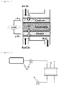
- FIG. 1 schematically illustrates an electricity generation principle of a solid oxide fuel cell.
- the solid oxide fuel cell comprises an electrolyte layer and a fuel electrode (anode) and a cathode (cathode) formed on both surfaces of the electrolyte layer.
- anode a fuel electrode
- cathode cathode
- FIG.1 illustrating the principle of electricity generation of the solid oxide fuel cell
- air is electrochemically reduced at the cathode to generate oxygen ions, and the produced oxygen ions are transferred to the anode through the electrolyte layer.
- fuel such as hydrogen, methanol, butane and the like is injected and the fuel is combined with the oxygen ions and electrochemically oxidized to emit electrons and generate water. This reaction causes electron transfer to an external circuit.
- the cathode may comprise an inorganic material having oxygen ion conductivity so as to be applicable to the cathode for the solid oxide fuel cell.
- the cathode may include at least one of lanthanum strontium manganese oxide (LSM), lanthanum strontium cobalt ferrite (LSCF), lanthanum strontium nickel ferrite (LSNF), lanthanum calcium nickel ferrite (LCNF), lanthanum strontium cobalt oxide (LSC), gadolinium strontium cobalt oxide (GSC), lanthanum strontium ferrite (LSF), samarium strontium cobalt oxide (SSC), barium strontium cobalt ferrite (BSCF), and lanthanum strontium gallium magnesium oxide (LSGM).
- LSM lanthanum strontium manganese oxide
- LSCF lanthanum strontium cobalt ferrite
- LSNF lanthanum strontium nickel ferrite
- LCNF lanthanum calcium nickel ferrite
- LSC lanthanum strontium cobalt oxide
- GSC gadolinium strontium cobalt
- the cathode may include at least one of lanthanum strontium cobalt ferrite (LSCF), lanthanum strontium cobalt oxide (LSC), and barium strontium cobalt ferrite (BSCF).
- LSCF lanthanum strontium cobalt ferrite
- LSC lanthanum strontium cobalt oxide
- BSCF barium strontium cobalt ferrite
- a thickness of the cathode may be 10 ⁇ m or more and 100 ⁇ m or less. Particularly, the thickness of the cathode may be 20 ⁇ m or more and 50 ⁇ m or less.
- the porosity of the cathode may be 10% or more and 50% or less. Particularly, the porosity of the cathode may be 10% or more and 30% or less.
- a diameter of a pore of the cathode may be 0.1 ⁇ m or more and 10 ⁇ m or less. Particularly, the diameter of the pore of the cathode may be 0.5 ⁇ m or more and 5 ⁇ m or less. More particularly, the diameter of the pore of the cathode may be 0.5 ⁇ m or more and 2 ⁇ m or less.
- the method for preparing the cathode is not particularly limited, but for example, a cathode may be prepared by coating cathode slurry and drying and firing the coated cathode slurry; or forming a green sheet for the cathode by coating and drying the cathode slurry on a separate release sheet, and one or more green sheets for the cathode may be fired alone or with a green sheet of adjacent heterogeneous layers to prepare the cathode.
- a thickness of the green sheet for the cathode may be 10 ⁇ m or more and 100 ⁇ m or less.
- the cathode slurry comprises inorganic particles having oxygen ion conductivity, and if necessary, the cathode slurry may further comprise at least one of a binder resin, a plasticizer, a dispersant, and a solvent.
- the binder resin, the plasticizer, the dispersant and the solvent are not particularly limited, and typical materials known in the art may be used.
- the content of the inorganic particles having oxygen ion conductivity may be 40 wt% or more and 70 wt% or less
- the content of the solvent may be 10 wt% or more and 30 wt% or less
- the content of the dispersant may be 5 wt% or more and 10 wt% or less
- the content of the plasticizer may be 0.5 wt% or more and 3 wt% or less
- the content of the binder may be 10 wt% or more and 30 wt% or less.
- the anode may comprise an inorganic material having oxygen ion conductivity so as to be applicable to the anode for the solid oxide fuel cell.
- YSZ Y 2 O 3 )
- the anode may comprise the same inorganic material as the metal oxide of the electrolyte.
- the anode may comprise the ceria-based metal oxide.
- the electrolyte comprises gadolinium doped ceria
- the anode may comprise the gadolinium doped ceria.
- a thickness of the anode may be 10 ⁇ m or more and 1000 ⁇ m or less. Particularly, the thickness of the anode may be 20 ⁇ m or more and 900 ⁇ m or less.
- the porosity of the anode may be 10% or more and 50% or less. Particularly, the porosity of the anode may be 10% or more and 30% or less.
- a diameter of a pore of the anode may be 0.1 ⁇ m or more and 10 ⁇ m or less. Particularly, the diameter of the pore of the anode may be 0.5 ⁇ m or more and 5 ⁇ m or less. More particularly, the diameter of the pore of the anode may be 0.5 ⁇ m or more and 2 ⁇ m or less.
- the method for preparing the anode is not particularly limited, but for example, a anode may be prepared by coating anode slurry and drying and firing the coated anode slurry; or forming a green sheet for the anode by coating and drying the anode slurry on a separate release sheet, and one or more green sheets for the anode may be fired alone or with a green sheet of adjacent heterogeneous layers to prepare the anode.
- a thickness of the green sheet for the anode may be 10 ⁇ m or more and 100 ⁇ m or less.
- the anode slurry comprises inorganic particles having oxygen ion conductivity, and if necessary, the anode slurry may further comprise at least one of a binder resin, a plasticizer, a dispersant, and a solvent.
- the binder resin, the plasticizer, the dispersant and the solvent are not particularly limited, and typical materials known in the art may be used.
- the content of the inorganic particles having oxygen ion conductivity may be 10 wt% or more and 50 wt% or less
- the content of the solvent may be 10 wt% or more and 30 wt% or less
- the content of the dispersant may be 5 wt% or more and 10 wt% or less
- the content of the plasticizer may be 0.5 wt% or more and 3 wt% or less
- the content of the binder may be 10 wt% or more and 30 wt% or less.
- the anode slurry may further comprise NiO.
- the content of NiO may be 35 wt% or more and 60 wt% or less based on the weight of the inorganic particles having oxygen ion conductivity.
- the anode may be provided on a separate porous ceramic support or a porous metal support, or may comprise an anode support and an anode functional layer.
- the anode support is a layer containing the same inorganic material as the anode functional layer, but supporting another layer due to higher porosity and a relatively larger thickness than the anode functional layer.
- the anode functional layer may be a layer which is provided between the anode support and the electrolyte layer to actually play a main role as the anode.
- the prepared green sheet for the anode is laminated on the fired porous ceramic support or porous metal support and then fired to prepare the anode.
- the anode may be prepared by laminating a green sheet for the prepared anode functional layer on the fired anode support and then firing the laminated green sheet.
- the thickness of the anode support may be 350 ⁇ m or more and 1000 ⁇ m or less, and the thickness of the anode functional layer may be 5 ⁇ m or more and 50 ⁇ m or less.
- the electrolyte may comprise ceria-based metal oxide.
- the ceria-based metal oxide is not particularly limited as long as having oxygen ion conductivity, but particularly, the ceria-based metal oxide may comprise at least one of samarium doped ceria and gadolinium doped ceria, and more particularly gadolinium doped ceria.
- a thickness of the electrolyte may be 10 ⁇ m or more and 100 ⁇ m or less. Particularly, the thickness of the electrolyte may be 20 ⁇ m or more and 50 ⁇ m or less.
- the method for preparing the electrolyte is not particularly limited, but for example, a electrolyte may be prepared by coating electrolyte slurry and drying and firing the coated electrolyte slurry; or forming a green sheet for the electrolyte by coating and drying the electrolyte slurry on a separate release sheet, and one or more green sheets for the electrolyte may be fired alone or with a green sheet of adjacent heterogeneous layers to prepare the electrolyte.
- a thickness of the green sheet for the electrolyte may be 10 ⁇ m or more and 100 ⁇ m or less.
- the electrolyte slurry comprises ceria-based metal oxide particles, and if necessary, the anode slurry may further comprise at least one of a binder resin, a plasticizer, a dispersant, and a solvent.
- a binder resin e.g., polystyrene resin
- plasticizer e.g., polystyrene resin
- the content of the ceria-based metal oxide particles may be 40 wt% or more and 70 wt% or less.
- the content of the solvent may be 10 wt% or more and 30 wt% or less
- the content of the dispersant may be 5 wt% or more and 10 wt% or less
- the content of the plasticizer may be 0.5 wt% or more and 3 wt% or less
- the content of the binder may be 10 wt% or more and 30 wt% or less.
- the green sheet means a film-like membrane which may be processed in a next process other than a complete end product.
- the green sheet is coated with a coating composition containing the inorganic particles and the solvent and then dried in a sheet form and means a semi-dried sheet capable of maintaining a sheet form while comprising a small amount of solvent.
- the form of the fuel cell is not limited, and for example, may be a coin type, a plate type, a cylinder type, a horn type, a button type, a sheet type, or a laminated type.
- the fuel cell may be particularly used as power of an electric vehicle, a hybrid electric vehicle, a plug-in hybrid electric vehicle or a power storage device.
- the present specification provides a battery module comprising the fuel cell as a unit cell.
- FIG. 2 schematically illustrates an embodiment of a battery module comprising a fuel cell, and the fuel cell comprises a battery module 60, an oxidizer supply unit 70, and a fuel supply unit 80.
- the battery module 60 comprises one or more fuel cells described above as unit cells, and comprises separators interposed between the unit cells when two or more unit cells are comprised.
- the separator serves to prevent the unit cells from being electrically connected to each other and transmit the fuel and the oxidizer supplied from the outside to the unit cells.
- the oxidizer supply unit 70 serves to supply the oxidizer to the battery module 60.
- oxygen is representatively used, and oxygen or air which is injected into the oxidizer supply unit 70 may be used.
- the fuel supply unit 80 serves to supply the fuel to the battery module 60 and comprises a fuel tank 81 storing the fuel and a pump 82 supplying the fuel stored in the fuel tank 81 to the battery module 60.
- a fuel tank 81 storing the fuel
- a pump 82 supplying the fuel stored in the fuel tank 81 to the battery module 60.
- gas or liquid hydrogen or hydrocarbon fuel may be used.
- hydrocarbon fuel may comprise methanol, ethanol, propanol, butanol or natural gas.
- a solid oxide fuel cell used for measurement was prepared by an anode support layer (ASL), an anode functional layer (AFL), an electrolyte layer (EL), and a cathode layer (CL).
- ASL anode support layer
- AFL an anode functional layer
- EL electrolyte layer
- CL cathode layer
- ASL slurry used GDC and NiO as an inorganic material, and in this case, a ratio of GDC and NiO was 50 : 50 vol%.
- the ASL slurry comprised a dispersant, a plasticizer, and a binder resin together with a solvent and was added with 50.2 wt% of the inorganic material, 18.2 wt% of the solvent, 6.2 wt% of the dispersant, 1.2 wt% of the plasticizer and 24.2 wt% of the binder based on the entire weight of the slurry.
- the ASL slurry was tape-cast to obtain an ASL green sheet having a thickness of 100 ⁇ m to 200 ⁇ m.
- AFL slurry had the same organic material as the ASL slurry except for the inorganic material, but a composition ratio of GDC and NiO was 60 : 40 vol%, and an AFL green sheet having a thickness of 10 ⁇ m thinner than that of the ASL was cast.
- EL slurry had the same organic material as the ASL slurry except for the inorganic material, but the inorganic material was made of GDC alone without NiO, and an EL green sheet having a thickness of 20 ⁇ m was cast using the EL slurry.
- the ASL green sheet, the AFL green sheet and the EL green sheet were sequentially laminated and then sintered at 1400°C to prepare a half cell.
- thicknesses of the ASL, the AFL, and the EL after sintering were 800 ⁇ m, 20 ⁇ m, and 20 ⁇ m, respectively.
- LSCF cathode composition containing 60 wt% of LSCF6428 (La 0.6 Sr 0.4 Co 0.2 Fe 0.8 O 3- ⁇ ) and 40 wt% of ESL441 as a binder composition based on the total weight of the entire composition was prepared in a form of paste using a three roll mill.
- the LSCF cathode composition was coated on the electrolyte layer of the above-prepared half cell by screen printing, dried, and then heat-treated at 1000°C to form a cathode.
- An SOFC stack to which a GDC electrolyte prepared in the Preparation Example was applied was driven by supplying hydrogen to an anode while supplying air to a cathode for about 2 hours at 600°C to reduce NiO to Ni and immediately supplying air and fuel to the cathode and the anode, respectively, without electrolyte oxidization.
- An SOFC stack to which a GDC electrolyte prepared in the Preparation Example was applied was driven by reducing an anode at 600°C and then supplying air and fuel to the cathode and the anode, respectively, without electrolyte oxidization, and thereafter, when the fuel supply was immediately stopped in an initial OCV state, it can be seen that the OCV was decreased to 680 mV through FIG. 4 (left).
- An SOFC stack to which a GDC electrolyte prepared in the Preparation Example was applied was driven by supplying hydrogen to an anode while supplying air to a cathode for about 2 hours at 600°C to reduce NiO to Ni and then, immediately supplying air and fuel to the cathode and the anode, respectively.
- An SOFC stack to which a GDC electrolyte prepared in the Preparation Example was applied was driven by supplying hydrogen to an anode while supplying air to a cathode for about 2 hours at 600°C to reduce NiO to Ni. Thereafter, the SOFC stack was driven by stopping the supply of hydrogen for 45 minutes to oxidize the electrolyte by oxygen of the air supplied to the cathode and immediately supplying air and fuel to the cathode and the anode, respectively.
- OCV open circuit voltage
Landscapes
- Engineering & Computer Science (AREA)
- Chemical & Material Sciences (AREA)
- Manufacturing & Machinery (AREA)
- Chemical Kinetics & Catalysis (AREA)
- Electrochemistry (AREA)
- General Chemical & Material Sciences (AREA)
- Life Sciences & Earth Sciences (AREA)
- Sustainable Development (AREA)
- Sustainable Energy (AREA)
- Materials Engineering (AREA)
- Fuel Cell (AREA)
- Inert Electrodes (AREA)
Abstract
Description
- This application claims priority to and the benefit of Korean Patent Application No.
10-2016-0126647 - The present specification relates to a method for driving a solid oxide fuel cell comprising an anode, a cathode, and an electrolyte provided between the anode and the cathode.
- Recently, depletion of existing energy sources such as oil and coal has been predicted, and interest in energy that can replace the energy is increasing. A fuel cell as one of the alternative energy has particularly received attention due to high efficiency and merits in that pollutants such as NOx and SOx are not discharged and the used fuel is abundant.
- The fuel cell is a power generation system that converts chemical reaction energy of the fuel and an oxidizer into electric energy, and hydrogen and hydrocarbons such as methanol and butane as the fuel and oxygen as the oxidizer are representatively used.
- The fuel cell includes a polymer electrolyte membrane fuel cell (PEMFC), a direct methanol fuel cell (DMFC), a phosphoric acid fuel cell (PAFC), an alkaline fuel cell (AFC), a molten carbonate fuel cell (MCFC), a solid oxide fuel cell (SOFC), and the like.
- Meanwhile, research on a metal air secondary battery that manufactures a cathode of the metal secondary battery as a cathode by applying a principle of the cathode of the fuel cell is required.
- The present specification has been made in an effort to provide a method for driving a solid oxide fuel cell comprising an anode, a cathode, and an electrolyte provided between the anode and the cathode.
- An exemplary embodiment of the present specification provides a method for driving a solid oxide fuel cell comprising an anode, a cathode, and an electrolyte provided between the anode and the cathode and containing ceria-based metal oxide, the method comprising: adjusting the solid oxide fuel cell to a driving temperature; reducing NiO of the anode to Ni by supplying gas containing oxygen to the cathode and supplying gas containing hydrogen to the anode; oxidizing the electrolyte by supplying gas containing oxygen to the cathode and stopping the supply of gas containing hydrogen to the reduced anode; and driving the solid oxide fuel cell by supplying gas containing oxygen to the cathode and supplying gas containing hydrogen to the reduced anode.
- According to the exemplary embodiment of the present specification, the electrolyte comprising ceria-based metal oxide can improve reduction durability for hydrogen.
- The method for driving the fuel cell according to the exemplary embodiment of the present specification has advantages of increasing an ion conductive contribution rate of the electrolyte and having high efficiency of the fuel cell.
-
-
FIG. 1 is a schematic diagram illustrating a principle of electricity generation of a solid oxide fuel cell. -
FIG. 2 is a diagram schematically illustrating an example of a battery module comprising a fuel cell. -
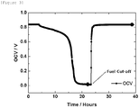
FIG. 3 is a graph illustrating a change in open circuit voltage during cell driving in Process Example 3. -
FIG. 4 is a graph illustrating a change in open circuit voltage according to fuel cut off and air cut off in Process Example 2. -
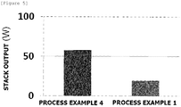
FIG. 5 is a comparative graph of stack output in Process Examples 1 and 4. -
- 60: Battery module
- 70: Oxidizer supply unit
- 80: Fuel supply unit
- 81: Fuel tank
- 82: Pump
- Hereinafter, the present specification will be described in detail.
- The present specification provides a method for driving a solid oxide fuel cell comprising an anode, a cathode, and an electrolyte provided between the anode and the cathode and containing ceria-based metal oxide.
- The method for driving the solid oxide fuel cell comprises:
- adjusting the solid oxide fuel cell to a driving temperature;
- reducing NiO of the anode to Ni by supplying gas containing oxygen to the cathode and supplying gas containing hydrogen to the anode;
- oxidizing the electrolyte by supplying gas containing oxygen to the cathode and stopping the supply of gas containing hydrogen to the reduced anode; and
- driving the solid oxide fuel cell by supplying gas containing oxygen to the cathode and supplying gas containing hydrogen to the reduced anode.
- The method for driving the solid oxide fuel cell comprises adjusting the solid oxide fuel cell to a driving temperature.
- The driving temperature of the solid oxide fuel cell may be 600°C or more and 650°C or less.
- When adjusting the solid oxide fuel cell to the driving temperature, air may be supplied to the anode and the cathode, respectively.
- The method for driving the solid oxide fuel cell may further comprise:
- before adjusting the driving temperature, preparing the solid oxide fuel cell in which the anode, the electrolyte, and the cathode are sequentially laminated;
- positioning and assembling the solid oxide fuel cell between two or more separators;
- coating a sealant on the solid oxide fuel cell;
- removing an additive from the sealant by increasing the temperature while supplying air to the anode and the cathode, respectively; and
- sealing the solid oxide fuel cell with the sealant by pressurizing the solid oxide fuel cell.
- The sealant comprises glass powder and may further comprise an additive comprising at least one of a binder, a plasticizer, a dispersant and a solvent. The binder, the plasticizer, the dispersant and the solvent are not particularly limited, and typical materials known in the art may be used.
- The sealant may further comprise metal oxide.
- In the removing of the additive from the sealant, the additive such as the binder, the plasticizer, the dispersant and the solvent may be removed except for the glass powder and in the case of further comprising metal oxide, the additive except for the glass powder and the metal oxide may be removed.
- In the sealing of the solid oxide fuel cell, the additive is removed, a fluid sealant is pressurized to move to a position to be sealed and fills an empty space to seal the solid oxide fuel cell.
- In the removing of the additive from the sealant, the final heating temperature may be 700°C or more and 800°C or less and particularly 700°C or more and 730°C or less.
- When in the removing of the additive from the sealant, the final heating temperature is 700°C or more and 800°C or less and the driving temperature of the solid oxide fuel cell is 600°C or more and 650°C or less, the temperature is increased to remove the additive from the sealant and then may be cooled to a driving temperature of the solid oxide fuel cell.
- The method for driving the solid oxide fuel cell comprises reducing NiO of the anode to Ni by supplying gas containing oxygen to the cathode and supplying gas containing hydrogen to the anode.
- The method for driving the solid oxide fuel cell comprises oxidizing the electrolyte by supplying the gas containing oxygen to the cathode and stopping the supply of the gas containing hydrogen to the reduced anode.
- The ceria-based metal oxide of the electrolyte has high ion conductivity, but has a disadvantage of low chemical stability. Particularly, in the ceria-based metal oxide, Ce tetravalent ions are easily reduced to trivalent ions by hydrogen, and the reduced ceria-based metal oxide has an increased electron conductive characteristic and a current flows.
- As a result, when the electrolyte comprises the reduced ceria-based metal oxide, a current may flow between the cathode and the anode by the electrolyte. As the current flows between the cathode and the anode, an open circuit voltage (OCV) drops and the energy conversion efficiency of the fuel cell may be reduced.
- Before the fuel cell is driven, the electrolyte is sufficiently oxidized through the electrolyte oxidation to improve the reduction durability for hydrogen of the electrolyte containing the ceria-based metal oxide.
- In the oxidizing of the electrolyte, the time for stopping the supply of the gas containing hydrogen to the reduced anode may be 2 minutes or more, particularly 2 minutes or more and 60 minutes or less, and more particularly 30 minutes or more and 40 minutes or less.
- In the oxidizing of the electrolyte, oxygen partial pressure (PO2) in the cell may be 10-34 or more and 1 or less, particularly 10-34 or more and 0.2 or less, and more particularly 10-5 or more and 0.2 or less.
- Herein, the oxygen partial pressure (PO2) means the number of oxygen molecules with respect to the total number of molecules in gas, and there is no separate unit.
- Through the electrolyte oxidation, it can be confirmed that the electrolyte is sufficiently oxidized by a change in OCV.
- Considering that the transference number of the ceria-based electrolyte is about 0.7, the open circuit voltage (OCV) determining that the electrolyte is sufficiently oxidized in the electrolyte oxidation is theoretically 875 mV or more. In other words, when the electrolyte is oxidized, it can be directly seen that when the OCV value of the solid oxide fuel cell is measured at 875 mV or more, the electrolyte is sufficiently oxidized.
- The method for driving the solid oxide fuel cell comprises driving the solid oxide fuel cell by supplying gas containing oxygen to the cathode and supplying gas containing hydrogen to the reduced anode.
- When the solid oxide fuel cell is driven, the open circuit voltage (OCV) of the solid oxide fuel cell may be 600 mV or more and 960 mV or less.
- The method for driving the solid oxide fuel cell may further comprise re-oxidizing the electrolyte by supplying gas containing oxygen to the cathode and stopping the supply of the gas containing hydrogen to the anode, after driving the solid oxide fuel cell.
- When the solid oxide fuel cell is driven and then the OCV is gradually reduced to be 0 mV or close to 0 mV, the supply of the gas containing hydrogen supplied during the driving of the solid oxide fuel cell is stopped and the electrolyte is oxidized again, and then the OCV of the solid oxide fuel cell may be recovered by the OCV at the initial stage of driving.
- Through the re-oxidizing of the electrolyte, it can be confirmed that the electrolyte is sufficiently oxidized by an OCV change which is recovered by OCV at the initial stage of driving.
- The present specification provides a solid oxide fuel cell driven according to the driving method and comprising an anode, a cathode, and an electrolyte provided between the anode and the cathode and containing ceria-based metal oxide.
-
FIG. 1 schematically illustrates an electricity generation principle of a solid oxide fuel cell. The solid oxide fuel cell comprises an electrolyte layer and a fuel electrode (anode) and a cathode (cathode) formed on both surfaces of the electrolyte layer. Referring toFIG.1 illustrating the principle of electricity generation of the solid oxide fuel cell, air is electrochemically reduced at the cathode to generate oxygen ions, and the produced oxygen ions are transferred to the anode through the electrolyte layer. In the anode, fuel such as hydrogen, methanol, butane and the like is injected and the fuel is combined with the oxygen ions and electrochemically oxidized to emit electrons and generate water. This reaction causes electron transfer to an external circuit. - The cathode may comprise an inorganic material having oxygen ion conductivity so as to be applicable to the cathode for the solid oxide fuel cell. The kind of inorganic material is not particularly limited, but the inorganic material may include at least one of yttria stabilized zirconia (YSZ; (Y2O3)x(ZrO2)1-x, x = 0.05 to 0.15), scandia stabilized zirconia (ScSZ; (Sc2O3)x(ZrO2)1-x, x = 0.05 to 0.15), samarium doped ceria (SDC; (Sm2O3)x(CeO2)1-x, x = 0.02 to 0.4), gadolinium doped ceria (GDC; (Gd2O3)x(CeO2)1-x, x = 0.02 to 0.4), lanthanum strontium manganese oxide (LSM), lanthanum strontium cobalt ferrite (LSCF), lanthanum strontium nickel ferrite (LSNF), lanthanum calcium nickel ferrite (LCNF), lanthanum strontium cobalt oxide (LSC), gadolinium strontium cobalt oxide (GSC), lanthanum strontium ferrite (LSF), samarium strontium cobalt oxide (SSC), barium strontium cobalt ferrite (BSCF), and lanthanum strontium gallium magnesium oxide (LSGM).
- The cathode may include at least one of lanthanum strontium manganese oxide (LSM), lanthanum strontium cobalt ferrite (LSCF), lanthanum strontium nickel ferrite (LSNF), lanthanum calcium nickel ferrite (LCNF), lanthanum strontium cobalt oxide (LSC), gadolinium strontium cobalt oxide (GSC), lanthanum strontium ferrite (LSF), samarium strontium cobalt oxide (SSC), barium strontium cobalt ferrite (BSCF), and lanthanum strontium gallium magnesium oxide (LSGM).
- The cathode may include at least one of lanthanum strontium cobalt ferrite (LSCF), lanthanum strontium cobalt oxide (LSC), and barium strontium cobalt ferrite (BSCF).
- A thickness of the cathode may be 10 µm or more and 100 µm or less. Particularly, the thickness of the cathode may be 20 µm or more and 50 µm or less.
- The porosity of the cathode may be 10% or more and 50% or less. Particularly, the porosity of the cathode may be 10% or more and 30% or less.
- A diameter of a pore of the cathode may be 0.1 µm or more and 10 µm or less. Particularly, the diameter of the pore of the cathode may be 0.5 µm or more and 5 µm or less. More particularly, the diameter of the pore of the cathode may be 0.5 µm or more and 2 µm or less.
- The method for preparing the cathode is not particularly limited, but for example, a cathode may be prepared by coating cathode slurry and drying and firing the coated cathode slurry; or forming a green sheet for the cathode by coating and drying the cathode slurry on a separate release sheet, and one or more green sheets for the cathode may be fired alone or with a green sheet of adjacent heterogeneous layers to prepare the cathode.
- A thickness of the green sheet for the cathode may be 10 µm or more and 100 µm or less.
- The cathode slurry comprises inorganic particles having oxygen ion conductivity, and if necessary, the cathode slurry may further comprise at least one of a binder resin, a plasticizer, a dispersant, and a solvent. The binder resin, the plasticizer, the dispersant and the solvent are not particularly limited, and typical materials known in the art may be used.
- Based on the total weight of the cathode slurry, the content of the inorganic particles having oxygen ion conductivity may be 40 wt% or more and 70 wt% or less, the content of the solvent may be 10 wt% or more and 30 wt% or less, the content of the dispersant may be 5 wt% or more and 10 wt% or less, the content of the plasticizer may be 0.5 wt% or more and 3 wt% or less, and the content of the binder may be 10 wt% or more and 30 wt% or less.
- The anode may comprise an inorganic material having oxygen ion conductivity so as to be applicable to the anode for the solid oxide fuel cell. The kind of inorganic material is not particularly limited, but the inorganic material may include at least one of yttria stabilized zirconia (YSZ: (Y2O3)x(ZrO2)1-x, x = 0.05 to 0.15), scandia stabilized zirconia (ScSZ: (Sc2O3)x(ZrO2)1-x, x = 0.05 to 0.15), samarium doped ceria (SDC: (Sm2O3)x(CeO2)1-x, x = 0.02 to 0.4), and gadolinium doped ceria (GDC: (Gd2O3)x(CeO2)1-x, x = 0.02 to 0.4).
- The anode may comprise the same inorganic material as the metal oxide of the electrolyte. Particularly, when the electrolyte comprises ceria-based metal oxide, the anode may comprise the ceria-based metal oxide. More particularly, when the electrolyte comprises gadolinium doped ceria, the anode may comprise the gadolinium doped ceria.
- A thickness of the anode may be 10 µm or more and 1000 µm or less. Particularly, the thickness of the anode may be 20 µm or more and 900 µm or less.
- The porosity of the anode may be 10% or more and 50% or less. Particularly, the porosity of the anode may be 10% or more and 30% or less.
- A diameter of a pore of the anode may be 0.1 µm or more and 10 µm or less. Particularly, the diameter of the pore of the anode may be 0.5 µm or more and 5 µm or less. More particularly, the diameter of the pore of the anode may be 0.5 µm or more and 2 µm or less.
- The method for preparing the anode is not particularly limited, but for example, a anode may be prepared by coating anode slurry and drying and firing the coated anode slurry; or forming a green sheet for the anode by coating and drying the anode slurry on a separate release sheet, and one or more green sheets for the anode may be fired alone or with a green sheet of adjacent heterogeneous layers to prepare the anode.
- A thickness of the green sheet for the anode may be 10 µm or more and 100 µm or less.
- The anode slurry comprises inorganic particles having oxygen ion conductivity, and if necessary, the anode slurry may further comprise at least one of a binder resin, a plasticizer, a dispersant, and a solvent. The binder resin, the plasticizer, the dispersant and the solvent are not particularly limited, and typical materials known in the art may be used.
- Based on the total weight of the anode slurry, the content of the inorganic particles having oxygen ion conductivity may be 10 wt% or more and 50 wt% or less, the content of the solvent may be 10 wt% or more and 30 wt% or less, the content of the dispersant may be 5 wt% or more and 10 wt% or less, the content of the plasticizer may be 0.5 wt% or more and 3 wt% or less, and the content of the binder may be 10 wt% or more and 30 wt% or less.
- The anode slurry may further comprise NiO. The content of NiO may be 35 wt% or more and 60 wt% or less based on the weight of the inorganic particles having oxygen ion conductivity.
- The anode may be provided on a separate porous ceramic support or a porous metal support, or may comprise an anode support and an anode functional layer. At this time, the anode support is a layer containing the same inorganic material as the anode functional layer, but supporting another layer due to higher porosity and a relatively larger thickness than the anode functional layer. The anode functional layer may be a layer which is provided between the anode support and the electrolyte layer to actually play a main role as the anode.
- When the anode is provided on the porous ceramic support or the porous metal support, the prepared green sheet for the anode is laminated on the fired porous ceramic support or porous metal support and then fired to prepare the anode.
- When the anode comprises the anode support and the anode functional layer, the anode may be prepared by laminating a green sheet for the prepared anode functional layer on the fired anode support and then firing the laminated green sheet.
- When the anode comprises the anode support and the anode functional layer, the thickness of the anode support may be 350 µm or more and 1000 µm or less, and the thickness of the anode functional layer may be 5 µm or more and 50 µm or less.
- The electrolyte may comprise ceria-based metal oxide.
- The ceria-based metal oxide is not particularly limited as long as having oxygen ion conductivity, but particularly, the ceria-based metal oxide may comprise at least one of samarium doped ceria and gadolinium doped ceria, and more particularly gadolinium doped ceria.
- A thickness of the electrolyte may be 10 µm or more and 100 µm or less. Particularly, the thickness of the electrolyte may be 20 µm or more and 50 µm or less.
- The method for preparing the electrolyte is not particularly limited, but for example, a electrolyte may be prepared by coating electrolyte slurry and drying and firing the coated electrolyte slurry; or forming a green sheet for the electrolyte by coating and drying the electrolyte slurry on a separate release sheet, and one or more green sheets for the electrolyte may be fired alone or with a green sheet of adjacent heterogeneous layers to prepare the electrolyte.
- A thickness of the green sheet for the electrolyte may be 10 µm or more and 100 µm or less.
- The electrolyte slurry comprises ceria-based metal oxide particles, and if necessary, the anode slurry may further comprise at least one of a binder resin, a plasticizer, a dispersant, and a solvent. The binder resin, the plasticizer, the dispersant and the solvent are not particularly limited, and typical materials known in the art may be used.
- Based on the total weight of the electrolyte slurry, the content of the ceria-based metal oxide particles may be 40 wt% or more and 70 wt% or less.
- Based on the total weight of the electrolyte slurry, the content of the solvent may be 10 wt% or more and 30 wt% or less, the content of the dispersant may be 5 wt% or more and 10 wt% or less, the content of the plasticizer may be 0.5 wt% or more and 3 wt% or less, and the content of the binder may be 10 wt% or more and 30 wt% or less.
- In the present specification, the green sheet means a film-like membrane which may be processed in a next process other than a complete end product. In other words, the green sheet is coated with a coating composition containing the inorganic particles and the solvent and then dried in a sheet form and means a semi-dried sheet capable of maintaining a sheet form while comprising a small amount of solvent.
- The form of the fuel cell is not limited, and for example, may be a coin type, a plate type, a cylinder type, a horn type, a button type, a sheet type, or a laminated type.
- The fuel cell may be particularly used as power of an electric vehicle, a hybrid electric vehicle, a plug-in hybrid electric vehicle or a power storage device.
- The present specification provides a battery module comprising the fuel cell as a unit cell.
-
FIG. 2 schematically illustrates an embodiment of a battery module comprising a fuel cell, and the fuel cell comprises abattery module 60, anoxidizer supply unit 70, and afuel supply unit 80. - The
battery module 60 comprises one or more fuel cells described above as unit cells, and comprises separators interposed between the unit cells when two or more unit cells are comprised. The separator serves to prevent the unit cells from being electrically connected to each other and transmit the fuel and the oxidizer supplied from the outside to the unit cells. - The
oxidizer supply unit 70 serves to supply the oxidizer to thebattery module 60. As the oxidizer, oxygen is representatively used, and oxygen or air which is injected into theoxidizer supply unit 70 may be used. - The
fuel supply unit 80 serves to supply the fuel to thebattery module 60 and comprises afuel tank 81 storing the fuel and apump 82 supplying the fuel stored in thefuel tank 81 to thebattery module 60. As the fuel, gas or liquid hydrogen or hydrocarbon fuel may be used. Examples of the hydrocarbon fuel may comprise methanol, ethanol, propanol, butanol or natural gas. - Hereinafter, the present specification will be described in more detail through Examples. However, the following Examples are just to exemplify the present specification and the present specification is not limited thereto.
- A solid oxide fuel cell used for measurement was prepared by an anode support layer (ASL), an anode functional layer (AFL), an electrolyte layer (EL), and a cathode layer (CL).
- ASL slurry used GDC and NiO as an inorganic material, and in this case, a ratio of GDC and NiO was 50 : 50 vol%.
- Further, the ASL slurry comprised a dispersant, a plasticizer, and a binder resin together with a solvent and was added with 50.2 wt% of the inorganic material, 18.2 wt% of the solvent, 6.2 wt% of the dispersant, 1.2 wt% of the plasticizer and 24.2 wt% of the binder based on the entire weight of the slurry. The ASL slurry was tape-cast to obtain an ASL green sheet having a thickness of 100 µm to 200 µm.
- AFL slurry had the same organic material as the ASL slurry except for the inorganic material, but a composition ratio of GDC and NiO was 60 : 40 vol%, and an AFL green sheet having a thickness of 10 µm thinner than that of the ASL was cast.
- EL slurry had the same organic material as the ASL slurry except for the inorganic material, but the inorganic material was made of GDC alone without NiO, and an EL green sheet having a thickness of 20 µm was cast using the EL slurry.
- The ASL green sheet, the AFL green sheet and the EL green sheet were sequentially laminated and then sintered at 1400°C to prepare a half cell. In this case, thicknesses of the ASL, the AFL, and the EL after sintering were 800 µm, 20 µm, and 20 µm, respectively.
- An LSCF cathode composition containing 60 wt% of LSCF6428 (La0.6Sr0.4Co0.2Fe0.8O3-δ) and 40 wt% of ESL441 as a binder composition based on the total weight of the entire composition was prepared in a form of paste using a three roll mill.
- The LSCF cathode composition was coated on the electrolyte layer of the above-prepared half cell by screen printing, dried, and then heat-treated at 1000°C to form a cathode.
- An SOFC stack to which a GDC electrolyte prepared in the Preparation Example was applied was driven by supplying hydrogen to an anode while supplying air to a cathode for about 2 hours at 600°C to reduce NiO to Ni and immediately supplying air and fuel to the cathode and the anode, respectively, without electrolyte oxidization.
- At this time, a current I and a voltage V were measured and a stack output I x V was calculated, and as a result, the output according to Process Example 1 was 19.28 W (see
FIG. 5 ). - As the result of measuring an open circuit voltage (OCV), it was confirmed that an initial OCV was 840 mV and the OCV was decreased to 0 after 18 hours.
- An SOFC stack to which a GDC electrolyte prepared in the Preparation Example was applied was driven by reducing an anode at 600°C and then supplying air and fuel to the cathode and the anode, respectively, without electrolyte oxidization, and thereafter, when the fuel supply was immediately stopped in an initial OCV state, it can be seen that the OCV was decreased to 680 mV through
FIG. 4 (left). - However, through
FIG. 4 (right), it can be seen that in the same condition, when the air in the cathode is stopped, the electrolyte is rapidly completely reduced and the OCV becomes 0 mV. - As a result, it can be seen that when the electrolyte is exposed to a reducing atmosphere, the anode and the cathode are electrically shorted and the OCV becomes 0.
- An SOFC stack to which a GDC electrolyte prepared in the Preparation Example was applied was driven by supplying hydrogen to an anode while supplying air to a cathode for about 2 hours at 600°C to reduce NiO to Ni and then, immediately supplying air and fuel to the cathode and the anode, respectively.
- An initial OCV was 840 mV and as the result of measuring an open circuit voltage (OCV), it was confirmed that the OCV was decreased to 0 after 18 hours.
- According to
FIG. 3 , as the result of measuring the OCV while driving, it was confirmed that the GDC electrolyte was reduced and the OCV was gradually decreased and finally, the OCV becomes 0. In this case, while the air supply to the cathode was maintained, the fuel supply to the anode was cut off for about 2 hours. As a result, it was confirmed that the initial OCV value was recovered to 840 mV. - An SOFC stack to which a GDC electrolyte prepared in the Preparation Example was applied was driven by supplying hydrogen to an anode while supplying air to a cathode for about 2 hours at 600°C to reduce NiO to Ni. Thereafter, the SOFC stack was driven by stopping the supply of hydrogen for 45 minutes to oxidize the electrolyte by oxygen of the air supplied to the cathode and immediately supplying air and fuel to the cathode and the anode, respectively. The result of measuring the open circuit voltage (OCV) was illustrated in
FIG. 3 . - At this time, a current I and a voltage V were measured and a stack output I x V was calculated, and as a result, the output according to Process Example 4 was 57.7 W (see
FIG. 5 ). As a result, it can be seen that the reduction stability of the electrolyte is increased and the stack output is increased through the electrolyte oxidation before the cell driving. - An initial OCV was 840 mV and as the result of measuring an open circuit voltage (OCV), it was confirmed that the OCV was decreased to 0 after 18 hours.
Claims (4)
- A method for driving a solid oxide fuel cell comprising an anode, a cathode, and an electrolyte provided between the anode and the cathode and containing ceria-based metal oxide, the method comprising:adjusting the solid oxide fuel cell to a driving temperature;reducing NiO of the anode to Ni by supplying gas containing oxygen to the cathode and supplying gas containing hydrogen to the anode;oxidizing the electrolyte by supplying the gas containing oxygen to the cathode and stopping the supply of the gas containing hydrogen to the reduced anode; anddriving the solid oxide fuel cell by supplying gas containing oxygen to the cathode and supplying gas containing hydrogen to the reduced anode.
- The method of claim 1, wherein the ceria-based metal oxide comprises at least one of samarium doped ceria and gadolinium doped ceria.
- The method of claim 1, wherein in the oxidizing of the electrolyte, the time of stopping the supply of the gas containing hydrogen to the reduced anode is 2 minutes or more and 60 minutes or less.
- The method of claim 1, wherein the driving temperature of the solid oxide fuel cell is 600°C or more and 650°C or less.
Applications Claiming Priority (2)
| Application Number | Priority Date | Filing Date | Title |
|---|---|---|---|
| KR1020160126647A KR102109231B1 (en) | 2016-09-30 | 2016-09-30 | Method for operating solid oxide fuel cell |
| PCT/KR2017/009263 WO2018062695A1 (en) | 2016-09-30 | 2017-08-24 | Method for operating solid oxide fuel cell |
Publications (3)
| Publication Number | Publication Date |
|---|---|
| EP3471184A1 true EP3471184A1 (en) | 2019-04-17 |
| EP3471184A4 EP3471184A4 (en) | 2019-06-26 |
| EP3471184B1 EP3471184B1 (en) | 2020-06-17 |
Family
ID=61762893
Family Applications (1)
| Application Number | Title | Priority Date | Filing Date |
|---|---|---|---|
| EP17856581.8A Active EP3471184B1 (en) | 2016-09-30 | 2017-08-24 | Method for operating solid oxide fuel cell |
Country Status (6)
| Country | Link |
|---|---|
| US (1) | US11043681B2 (en) |
| EP (1) | EP3471184B1 (en) |
| JP (1) | JP6780712B2 (en) |
| KR (1) | KR102109231B1 (en) |
| CN (1) | CN109417179B (en) |
| WO (1) | WO2018062695A1 (en) |
Families Citing this family (2)
| Publication number | Priority date | Publication date | Assignee | Title |
|---|---|---|---|---|
| CN114361543A (en) * | 2022-01-06 | 2022-04-15 | 徐州华清京昆能源有限公司 | Preparation method of high-flatness low-stress solid oxide fuel cell |
| KR102861076B1 (en) * | 2024-06-04 | 2025-09-16 | 삼성이앤에이 주식회사 | A method of operating high temperature electrolysis stack |
Family Cites Families (18)
| Publication number | Priority date | Publication date | Assignee | Title |
|---|---|---|---|---|
| JP4024164B2 (en) | 2003-02-27 | 2007-12-19 | 日本電信電話株式会社 | Operation method of solid oxide fuel cell |
| JP5122083B2 (en) * | 2006-05-22 | 2013-01-16 | 三菱マテリアル株式会社 | Fuel cell power generator, control program, and control method for fuel cell power generator |
| JP2010061829A (en) | 2008-09-01 | 2010-03-18 | Nippon Telegr & Teleph Corp <Ntt> | Operation method of solid oxide fuel cell |
| TWI385851B (en) * | 2009-07-03 | 2013-02-11 | Iner Aec Executive Yuan | Solid oxide fuel cell and manufacture method thereof |
| KR101110850B1 (en) | 2009-07-22 | 2012-02-16 | 연세대학교 산학협력단 | Electronic Conductivity Control In SOFC Electrolyte Of SOFC By Oxygen Partial Pressure In Anode And Working Method Thereof |
| KR101519667B1 (en) * | 2009-11-30 | 2015-05-13 | 현대자동차주식회사 | How to Activate Fuel Cell Acceleration |
| EP2621006B1 (en) * | 2012-01-26 | 2016-10-26 | Institute of Nuclear Energy Research Atomic Energy Council | An anode on a pretreated substrate for improving redox-stablility of solid oxide fuel cell and the fabrication method thereof |
| KR101342528B1 (en) * | 2012-05-22 | 2013-12-17 | 쌍용머티리얼 주식회사 | Operation conditions for direct hydrocarbon solid oxide fuel cells |
| JP2014053177A (en) | 2012-09-07 | 2014-03-20 | Nippon Telegr & Teleph Corp <Ntt> | Solid oxide fuel cell system and method for stopping solid oxide fuel cell system |
| CN103811789A (en) * | 2012-11-07 | 2014-05-21 | 中国科学院上海硅酸盐研究所 | Solid oxide fuel cell with symmetrical electrodes, and preparation method and application thereof |
| CN103887549B (en) * | 2012-12-21 | 2016-04-20 | 中国科学院大连化学物理研究所 | A kind of Solid Oxide Fuel Cell composite electrolyte film and preparation thereof |
| GB2517927B (en) | 2013-09-04 | 2018-05-16 | Ceres Ip Co Ltd | Process for forming a metal supported solid oxide fuel cell |
| JP6241651B2 (en) | 2013-09-27 | 2017-12-06 | Toto株式会社 | Solid oxide fuel cell device |
| JP2015191833A (en) * | 2014-03-28 | 2015-11-02 | Toto株式会社 | solid oxide fuel cell system |
| US10431841B2 (en) | 2014-11-18 | 2019-10-01 | Lg Chem, Ltd. | Method for manufacturing solid oxide fuel cell |
| JP6532668B2 (en) | 2014-11-19 | 2019-06-19 | 東京瓦斯株式会社 | Fuel cell system |
| KR101656156B1 (en) * | 2014-12-31 | 2016-09-09 | 세종대학교산학협력단 | Method for operating Solid Oxide Fuel Cell |
| CN104779409B (en) * | 2015-04-27 | 2018-08-24 | 上海邦民新能源科技有限公司 | A kind of solid oxide fuel cell and preparation method thereof |
-
2016
- 2016-09-30 KR KR1020160126647A patent/KR102109231B1/en active Active
-
2017
- 2017-08-24 JP JP2018565730A patent/JP6780712B2/en active Active
- 2017-08-24 WO PCT/KR2017/009263 patent/WO2018062695A1/en not_active Ceased
- 2017-08-24 CN CN201780042958.9A patent/CN109417179B/en active Active
- 2017-08-24 EP EP17856581.8A patent/EP3471184B1/en active Active
- 2017-08-24 US US16/310,923 patent/US11043681B2/en active Active
Also Published As
| Publication number | Publication date |
|---|---|
| EP3471184B1 (en) | 2020-06-17 |
| US20200313206A1 (en) | 2020-10-01 |
| US11043681B2 (en) | 2021-06-22 |
| CN109417179B (en) | 2022-04-01 |
| KR20180036271A (en) | 2018-04-09 |
| JP6780712B2 (en) | 2020-11-04 |
| CN109417179A (en) | 2019-03-01 |
| EP3471184A4 (en) | 2019-06-26 |
| KR102109231B1 (en) | 2020-05-11 |
| WO2018062695A1 (en) | 2018-04-05 |
| JP2019519076A (en) | 2019-07-04 |
Similar Documents
| Publication | Publication Date | Title |
|---|---|---|
| KR20160087516A (en) | Low and intermediate-temperature type proton-conducting ceramic fuel cells containing bi-layer electrolyte structure for preventing performance degradation and method for manufacturing the same | |
| EP3447833B1 (en) | Solid oxide fuel cell | |
| KR20170124819A (en) | Air electrode structure, fuel cell comprising the same, battery module comprising the fuel cell and method of manufacturing the air electrode structure | |
| JP6440178B2 (en) | Flat plate type solid oxide fuel cell and battery module including the same | |
| US11043681B2 (en) | Method for operating solid oxide fuel cell | |
| KR102103053B1 (en) | Flat-type solid oxide fuel cell | |
| KR102123721B1 (en) | Anode, electrode structure, fuel cell comprising the same and method thereof | |
| KR20180033826A (en) | Solid oxide fuel cell and manufacturing method thereof | |
| CN107210470A (en) | Solid oxide fuel cell manufacturing method, solid oxide fuel cell, and battery module including same | |
| KR102129651B1 (en) | Cathod green sheet for solid oxide fuel cell and solid oxide fuel cell | |
| KR20170010625A (en) | Greensheet laminate for solid oxide fuel cell and method for manufacturing solid oxide fuel cell | |
| KR102079846B1 (en) | Method for operating solid oxide fuel cell and solid oxide fuel cell operated thereby | |
| EP3343684B1 (en) | Solid oxide fuel cell and cell module comprising same | |
| KR20170044462A (en) | Solid oxide fuel cell, battery module comprising the same and method for manufacturing solid oxide fuel cell | |
| KR20170014639A (en) | Greensheet laminate for solid oxide fuel cell and method for manufacturing solid oxide fuel cell | |
| KR20190089324A (en) | Solid oxide fuel cell and manufacturing method thereof |
Legal Events
| Date | Code | Title | Description |
|---|---|---|---|
| STAA | Information on the status of an ep patent application or granted ep patent |
Free format text: STATUS: THE INTERNATIONAL PUBLICATION HAS BEEN MADE |
|
| PUAI | Public reference made under article 153(3) epc to a published international application that has entered the european phase |
Free format text: ORIGINAL CODE: 0009012 |
|
| STAA | Information on the status of an ep patent application or granted ep patent |
Free format text: STATUS: REQUEST FOR EXAMINATION WAS MADE |
|
| 17P | Request for examination filed |
Effective date: 20190108 |
|
| AK | Designated contracting states |
Kind code of ref document: A1 Designated state(s): AL AT BE BG CH CY CZ DE DK EE ES FI FR GB GR HR HU IE IS IT LI LT LU LV MC MK MT NL NO PL PT RO RS SE SI SK SM TR |
|
| AX | Request for extension of the european patent |
Extension state: BA ME |
|
| A4 | Supplementary search report drawn up and despatched |
Effective date: 20190529 |
|
| RIC1 | Information provided on ipc code assigned before grant |
Ipc: H01M 8/04746 20160101ALI20190523BHEP Ipc: H01M 8/124 20160101ALI20190523BHEP Ipc: H01M 8/04701 20160101AFI20190523BHEP Ipc: H01M 8/04089 20160101ALI20190523BHEP |
|
| DAV | Request for validation of the european patent (deleted) | ||
| DAX | Request for extension of the european patent (deleted) | ||
| GRAP | Despatch of communication of intention to grant a patent |
Free format text: ORIGINAL CODE: EPIDOSNIGR1 |
|
| STAA | Information on the status of an ep patent application or granted ep patent |
Free format text: STATUS: GRANT OF PATENT IS INTENDED |
|
| INTG | Intention to grant announced |
Effective date: 20200206 |
|
| GRAS | Grant fee paid |
Free format text: ORIGINAL CODE: EPIDOSNIGR3 |
|
| GRAA | (expected) grant |
Free format text: ORIGINAL CODE: 0009210 |
|
| STAA | Information on the status of an ep patent application or granted ep patent |
Free format text: STATUS: THE PATENT HAS BEEN GRANTED |
|
| AK | Designated contracting states |
Kind code of ref document: B1 Designated state(s): AL AT BE BG CH CY CZ DE DK EE ES FI FR GB GR HR HU IE IS IT LI LT LU LV MC MK MT NL NO PL PT RO RS SE SI SK SM TR |
|
| REG | Reference to a national code |
Ref country code: GB Ref legal event code: FG4D |
|
| REG | Reference to a national code |
Ref country code: CH Ref legal event code: EP |
|
| REG | Reference to a national code |
Ref country code: DE Ref legal event code: R096 Ref document number: 602017018501 Country of ref document: DE |
|
| REG | Reference to a national code |
Ref country code: IE Ref legal event code: FG4D |
|
| REG | Reference to a national code |
Ref country code: AT Ref legal event code: REF Ref document number: 1282444 Country of ref document: AT Kind code of ref document: T Effective date: 20200715 |
|
| PG25 | Lapsed in a contracting state [announced via postgrant information from national office to epo] |
Ref country code: LT Free format text: LAPSE BECAUSE OF FAILURE TO SUBMIT A TRANSLATION OF THE DESCRIPTION OR TO PAY THE FEE WITHIN THE PRESCRIBED TIME-LIMIT Effective date: 20200617 Ref country code: FI Free format text: LAPSE BECAUSE OF FAILURE TO SUBMIT A TRANSLATION OF THE DESCRIPTION OR TO PAY THE FEE WITHIN THE PRESCRIBED TIME-LIMIT Effective date: 20200617 Ref country code: GR Free format text: LAPSE BECAUSE OF FAILURE TO SUBMIT A TRANSLATION OF THE DESCRIPTION OR TO PAY THE FEE WITHIN THE PRESCRIBED TIME-LIMIT Effective date: 20200918 Ref country code: NO Free format text: LAPSE BECAUSE OF FAILURE TO SUBMIT A TRANSLATION OF THE DESCRIPTION OR TO PAY THE FEE WITHIN THE PRESCRIBED TIME-LIMIT Effective date: 20200917 Ref country code: SE Free format text: LAPSE BECAUSE OF FAILURE TO SUBMIT A TRANSLATION OF THE DESCRIPTION OR TO PAY THE FEE WITHIN THE PRESCRIBED TIME-LIMIT Effective date: 20200617 |
|
| REG | Reference to a national code |
Ref country code: LT Ref legal event code: MG4D |
|
| REG | Reference to a national code |
Ref country code: NL Ref legal event code: MP Effective date: 20200617 |
|
| PG25 | Lapsed in a contracting state [announced via postgrant information from national office to epo] |
Ref country code: LV Free format text: LAPSE BECAUSE OF FAILURE TO SUBMIT A TRANSLATION OF THE DESCRIPTION OR TO PAY THE FEE WITHIN THE PRESCRIBED TIME-LIMIT Effective date: 20200617 Ref country code: RS Free format text: LAPSE BECAUSE OF FAILURE TO SUBMIT A TRANSLATION OF THE DESCRIPTION OR TO PAY THE FEE WITHIN THE PRESCRIBED TIME-LIMIT Effective date: 20200617 Ref country code: HR Free format text: LAPSE BECAUSE OF FAILURE TO SUBMIT A TRANSLATION OF THE DESCRIPTION OR TO PAY THE FEE WITHIN THE PRESCRIBED TIME-LIMIT Effective date: 20200617 Ref country code: BG Free format text: LAPSE BECAUSE OF FAILURE TO SUBMIT A TRANSLATION OF THE DESCRIPTION OR TO PAY THE FEE WITHIN THE PRESCRIBED TIME-LIMIT Effective date: 20200917 |
|
| REG | Reference to a national code |
Ref country code: AT Ref legal event code: MK05 Ref document number: 1282444 Country of ref document: AT Kind code of ref document: T Effective date: 20200617 |
|
| PG25 | Lapsed in a contracting state [announced via postgrant information from national office to epo] |
Ref country code: NL Free format text: LAPSE BECAUSE OF FAILURE TO SUBMIT A TRANSLATION OF THE DESCRIPTION OR TO PAY THE FEE WITHIN THE PRESCRIBED TIME-LIMIT Effective date: 20200617 Ref country code: AL Free format text: LAPSE BECAUSE OF FAILURE TO SUBMIT A TRANSLATION OF THE DESCRIPTION OR TO PAY THE FEE WITHIN THE PRESCRIBED TIME-LIMIT Effective date: 20200617 |
|
| PG25 | Lapsed in a contracting state [announced via postgrant information from national office to epo] |
Ref country code: CZ Free format text: LAPSE BECAUSE OF FAILURE TO SUBMIT A TRANSLATION OF THE DESCRIPTION OR TO PAY THE FEE WITHIN THE PRESCRIBED TIME-LIMIT Effective date: 20200617 Ref country code: IT Free format text: LAPSE BECAUSE OF FAILURE TO SUBMIT A TRANSLATION OF THE DESCRIPTION OR TO PAY THE FEE WITHIN THE PRESCRIBED TIME-LIMIT Effective date: 20200617 Ref country code: SM Free format text: LAPSE BECAUSE OF FAILURE TO SUBMIT A TRANSLATION OF THE DESCRIPTION OR TO PAY THE FEE WITHIN THE PRESCRIBED TIME-LIMIT Effective date: 20200617 Ref country code: EE Free format text: LAPSE BECAUSE OF FAILURE TO SUBMIT A TRANSLATION OF THE DESCRIPTION OR TO PAY THE FEE WITHIN THE PRESCRIBED TIME-LIMIT Effective date: 20200617 Ref country code: AT Free format text: LAPSE BECAUSE OF FAILURE TO SUBMIT A TRANSLATION OF THE DESCRIPTION OR TO PAY THE FEE WITHIN THE PRESCRIBED TIME-LIMIT Effective date: 20200617 Ref country code: ES Free format text: LAPSE BECAUSE OF FAILURE TO SUBMIT A TRANSLATION OF THE DESCRIPTION OR TO PAY THE FEE WITHIN THE PRESCRIBED TIME-LIMIT Effective date: 20200617 Ref country code: PT Free format text: LAPSE BECAUSE OF FAILURE TO SUBMIT A TRANSLATION OF THE DESCRIPTION OR TO PAY THE FEE WITHIN THE PRESCRIBED TIME-LIMIT Effective date: 20201019 Ref country code: RO Free format text: LAPSE BECAUSE OF FAILURE TO SUBMIT A TRANSLATION OF THE DESCRIPTION OR TO PAY THE FEE WITHIN THE PRESCRIBED TIME-LIMIT Effective date: 20200617 |
|
| PG25 | Lapsed in a contracting state [announced via postgrant information from national office to epo] |
Ref country code: SK Free format text: LAPSE BECAUSE OF FAILURE TO SUBMIT A TRANSLATION OF THE DESCRIPTION OR TO PAY THE FEE WITHIN THE PRESCRIBED TIME-LIMIT Effective date: 20200617 Ref country code: PL Free format text: LAPSE BECAUSE OF FAILURE TO SUBMIT A TRANSLATION OF THE DESCRIPTION OR TO PAY THE FEE WITHIN THE PRESCRIBED TIME-LIMIT Effective date: 20200617 Ref country code: IS Free format text: LAPSE BECAUSE OF FAILURE TO SUBMIT A TRANSLATION OF THE DESCRIPTION OR TO PAY THE FEE WITHIN THE PRESCRIBED TIME-LIMIT Effective date: 20201017 |
|
| REG | Reference to a national code |
Ref country code: DE Ref legal event code: R097 Ref document number: 602017018501 Country of ref document: DE |
|
| PG25 | Lapsed in a contracting state [announced via postgrant information from national office to epo] |
Ref country code: MC Free format text: LAPSE BECAUSE OF FAILURE TO SUBMIT A TRANSLATION OF THE DESCRIPTION OR TO PAY THE FEE WITHIN THE PRESCRIBED TIME-LIMIT Effective date: 20200617 |
|
| REG | Reference to a national code |
Ref country code: CH Ref legal event code: PL |
|
| PLBE | No opposition filed within time limit |
Free format text: ORIGINAL CODE: 0009261 |
|
| STAA | Information on the status of an ep patent application or granted ep patent |
Free format text: STATUS: NO OPPOSITION FILED WITHIN TIME LIMIT |
|
| PG25 | Lapsed in a contracting state [announced via postgrant information from national office to epo] |
Ref country code: LI Free format text: LAPSE BECAUSE OF NON-PAYMENT OF DUE FEES Effective date: 20200831 Ref country code: LU Free format text: LAPSE BECAUSE OF NON-PAYMENT OF DUE FEES Effective date: 20200824 Ref country code: CH Free format text: LAPSE BECAUSE OF NON-PAYMENT OF DUE FEES Effective date: 20200831 Ref country code: DK Free format text: LAPSE BECAUSE OF FAILURE TO SUBMIT A TRANSLATION OF THE DESCRIPTION OR TO PAY THE FEE WITHIN THE PRESCRIBED TIME-LIMIT Effective date: 20200617 |
|
| 26N | No opposition filed |
Effective date: 20210318 |
|
| REG | Reference to a national code |
Ref country code: BE Ref legal event code: MM Effective date: 20200831 |
|
| PG25 | Lapsed in a contracting state [announced via postgrant information from national office to epo] |
Ref country code: SI Free format text: LAPSE BECAUSE OF FAILURE TO SUBMIT A TRANSLATION OF THE DESCRIPTION OR TO PAY THE FEE WITHIN THE PRESCRIBED TIME-LIMIT Effective date: 20200617 |
|
| PG25 | Lapsed in a contracting state [announced via postgrant information from national office to epo] |
Ref country code: IE Free format text: LAPSE BECAUSE OF NON-PAYMENT OF DUE FEES Effective date: 20200824 Ref country code: BE Free format text: LAPSE BECAUSE OF NON-PAYMENT OF DUE FEES Effective date: 20200831 |
|
| PG25 | Lapsed in a contracting state [announced via postgrant information from national office to epo] |
Ref country code: TR Free format text: LAPSE BECAUSE OF FAILURE TO SUBMIT A TRANSLATION OF THE DESCRIPTION OR TO PAY THE FEE WITHIN THE PRESCRIBED TIME-LIMIT Effective date: 20200617 Ref country code: MT Free format text: LAPSE BECAUSE OF FAILURE TO SUBMIT A TRANSLATION OF THE DESCRIPTION OR TO PAY THE FEE WITHIN THE PRESCRIBED TIME-LIMIT Effective date: 20200617 Ref country code: CY Free format text: LAPSE BECAUSE OF FAILURE TO SUBMIT A TRANSLATION OF THE DESCRIPTION OR TO PAY THE FEE WITHIN THE PRESCRIBED TIME-LIMIT Effective date: 20200617 |
|
| PG25 | Lapsed in a contracting state [announced via postgrant information from national office to epo] |
Ref country code: MK Free format text: LAPSE BECAUSE OF FAILURE TO SUBMIT A TRANSLATION OF THE DESCRIPTION OR TO PAY THE FEE WITHIN THE PRESCRIBED TIME-LIMIT Effective date: 20200617 |
|
| PGFP | Annual fee paid to national office [announced via postgrant information from national office to epo] |
Ref country code: DE Payment date: 20250721 Year of fee payment: 9 |
|
| PGFP | Annual fee paid to national office [announced via postgrant information from national office to epo] |
Ref country code: GB Payment date: 20250722 Year of fee payment: 9 |
|
| PGFP | Annual fee paid to national office [announced via postgrant information from national office to epo] |
Ref country code: FR Payment date: 20250725 Year of fee payment: 9 |