EP3470897A1 - Multicore optical connector and method for manufacturing same - Google Patents
Multicore optical connector and method for manufacturing same Download PDFInfo
- Publication number
- EP3470897A1 EP3470897A1 EP17810027.7A EP17810027A EP3470897A1 EP 3470897 A1 EP3470897 A1 EP 3470897A1 EP 17810027 A EP17810027 A EP 17810027A EP 3470897 A1 EP3470897 A1 EP 3470897A1
- Authority
- EP
- European Patent Office
- Prior art keywords
- ferrules
- lenses
- optical fibers
- end faces
- central axis
- Prior art date
- Legal status (The legal status is an assumption and is not a legal conclusion. Google has not performed a legal analysis and makes no representation as to the accuracy of the status listed.)
- Pending
Links
Images



Classifications
-
- G—PHYSICS
- G02—OPTICS
- G02B—OPTICAL ELEMENTS, SYSTEMS OR APPARATUS
- G02B6/00—Light guides; Structural details of arrangements comprising light guides and other optical elements, e.g. couplings
- G02B6/24—Coupling light guides
- G02B6/255—Splicing of light guides, e.g. by fusion or bonding
-
- G—PHYSICS
- G02—OPTICS
- G02B—OPTICAL ELEMENTS, SYSTEMS OR APPARATUS
- G02B6/00—Light guides; Structural details of arrangements comprising light guides and other optical elements, e.g. couplings
- G02B6/24—Coupling light guides
- G02B6/255—Splicing of light guides, e.g. by fusion or bonding
- G02B6/2552—Splicing of light guides, e.g. by fusion or bonding reshaping or reforming of light guides for coupling using thermal heating, e.g. tapering, forming of a lens on light guide ends
-
- G—PHYSICS
- G02—OPTICS
- G02B—OPTICAL ELEMENTS, SYSTEMS OR APPARATUS
- G02B6/00—Light guides; Structural details of arrangements comprising light guides and other optical elements, e.g. couplings
- G02B6/24—Coupling light guides
- G02B6/26—Optical coupling means
- G02B6/32—Optical coupling means having lens focusing means positioned between opposed fibre ends
-
- G—PHYSICS
- G02—OPTICS
- G02B—OPTICAL ELEMENTS, SYSTEMS OR APPARATUS
- G02B6/00—Light guides; Structural details of arrangements comprising light guides and other optical elements, e.g. couplings
- G02B6/24—Coupling light guides
- G02B6/36—Mechanical coupling means
- G02B6/38—Mechanical coupling means having fibre to fibre mating means
- G02B6/3807—Dismountable connectors, i.e. comprising plugs
- G02B6/381—Dismountable connectors, i.e. comprising plugs of the ferrule type, e.g. fibre ends embedded in ferrules, connecting a pair of fibres
- G02B6/3818—Dismountable connectors, i.e. comprising plugs of the ferrule type, e.g. fibre ends embedded in ferrules, connecting a pair of fibres of a low-reflection-loss type
- G02B6/3822—Dismountable connectors, i.e. comprising plugs of the ferrule type, e.g. fibre ends embedded in ferrules, connecting a pair of fibres of a low-reflection-loss type with beveled fibre ends
-
- G—PHYSICS
- G02—OPTICS
- G02B—OPTICAL ELEMENTS, SYSTEMS OR APPARATUS
- G02B6/00—Light guides; Structural details of arrangements comprising light guides and other optical elements, e.g. couplings
- G02B6/24—Coupling light guides
- G02B6/36—Mechanical coupling means
- G02B6/38—Mechanical coupling means having fibre to fibre mating means
- G02B6/3807—Dismountable connectors, i.e. comprising plugs
- G02B6/3833—Details of mounting fibres in ferrules; Assembly methods; Manufacture
- G02B6/3853—Lens inside the ferrule
-
- G—PHYSICS
- G02—OPTICS
- G02B—OPTICAL ELEMENTS, SYSTEMS OR APPARATUS
- G02B6/00—Light guides; Structural details of arrangements comprising light guides and other optical elements, e.g. couplings
- G02B6/24—Coupling light guides
- G02B6/36—Mechanical coupling means
- G02B6/38—Mechanical coupling means having fibre to fibre mating means
- G02B6/3807—Dismountable connectors, i.e. comprising plugs
- G02B6/3833—Details of mounting fibres in ferrules; Assembly methods; Manufacture
- G02B6/3863—Details of mounting fibres in ferrules; Assembly methods; Manufacture fabricated by using polishing techniques
-
- G—PHYSICS
- G02—OPTICS
- G02B—OPTICAL ELEMENTS, SYSTEMS OR APPARATUS
- G02B6/00—Light guides; Structural details of arrangements comprising light guides and other optical elements, e.g. couplings
- G02B6/24—Coupling light guides
- G02B6/36—Mechanical coupling means
- G02B6/38—Mechanical coupling means having fibre to fibre mating means
- G02B6/3807—Dismountable connectors, i.e. comprising plugs
- G02B6/3873—Connectors using guide surfaces for aligning ferrule ends, e.g. tubes, sleeves, V-grooves, rods, pins, balls
- G02B6/3882—Connectors using guide surfaces for aligning ferrule ends, e.g. tubes, sleeves, V-grooves, rods, pins, balls using rods, pins or balls to align a pair of ferrule ends
-
- G—PHYSICS
- G02—OPTICS
- G02B—OPTICAL ELEMENTS, SYSTEMS OR APPARATUS
- G02B6/00—Light guides; Structural details of arrangements comprising light guides and other optical elements, e.g. couplings
- G02B6/24—Coupling light guides
- G02B6/36—Mechanical coupling means
- G02B6/38—Mechanical coupling means having fibre to fibre mating means
- G02B6/3807—Dismountable connectors, i.e. comprising plugs
- G02B6/3873—Connectors using guide surfaces for aligning ferrule ends, e.g. tubes, sleeves, V-grooves, rods, pins, balls
- G02B6/3885—Multicore or multichannel optical connectors, i.e. one single ferrule containing more than one fibre, e.g. ribbon type
-
- G—PHYSICS
- G02—OPTICS
- G02B—OPTICAL ELEMENTS, SYSTEMS OR APPARATUS
- G02B6/00—Light guides; Structural details of arrangements comprising light guides and other optical elements, e.g. couplings
- G02B6/24—Coupling light guides
- G02B6/36—Mechanical coupling means
- G02B6/40—Mechanical coupling means having fibre bundle mating means
-
- G—PHYSICS
- G02—OPTICS
- G02B—OPTICAL ELEMENTS, SYSTEMS OR APPARATUS
- G02B6/00—Light guides; Structural details of arrangements comprising light guides and other optical elements, e.g. couplings
- G02B6/24—Coupling light guides
- G02B6/36—Mechanical coupling means
- G02B6/40—Mechanical coupling means having fibre bundle mating means
- G02B6/403—Mechanical coupling means having fibre bundle mating means of the ferrule type, connecting a pair of ferrules
Definitions
- the present invention relates to a multicore optical connector and a method of manufacturing the same.
- Optical interconnection is attracting attention as technology for achieving higher speed, larger capacity, and lower power consumption in information transmission.
- Important element technology in optical interconnection is connection technology of optical wiring, and connections that are simple but provide high coupling efficiency are required not only for connecting optical fibers with each other but also for connecting optical wiring between boards, between chips, and within chips.
- a connector connection using a connecting terminal called a ferrule is generally known, and configuring connectors to have multiple cores is essential in realizing connections of high-density optical wiring.
- a known multicore optical connector is provided with: ferrules having positioning holes in which a plurality of end portions of optical fibers are arranged and a pair of guide holes into which guide pins are to be inserted; and the guide pins which are inserted into the guide holes of the ferrules to coaxially connect a pair of the ferrules (refer to PTL 1 below).
- an optical fiber with lens in which a GRIN lens (a gradient index lens) is fused to a tip of an optical fiber is known (refer to PTL 2 below).
- a connection of optical wiring using an optical fiber with lens has features that enables energy density of emitted light to be reduced due to beam expansion by a GRIN lens and, at the same time, enables connecting end faces to be mutually contactless.
- reflection return light can be reduced and inverse incidence of reflection return light to the optical fiber can be prevented by inclining an end face of the GRIN lens relative to a central axis of the GRIN lens or the optical fiber.
- Snell's law since inclining the end face of the GRIN lens causes an optical axis of coupled light to have a prescribed angle relative to the central axis of the GRIN lens, when connecting a pair of ferrules using a multicore optical connector by coaxially butting the ferrules against each other, optical coupling cannot be performed if a central axis of the ferrules and a center of arrangement of GRIN lenses match each other.
- an object of the present invention is, for example, to enable, in a multicore optical connector in which a plurality of optical fibers with lenses are arranged and held in a ferrule, reflection return light to be suppressed and low-loss connection to be performed.
- a multicore optical connector and a method of manufacturing the same according to the present invention are configured as follows.
- a multicore optical connector including: a ferrule in which a plurality of optical fibers with lenses are arranged and held, the optical fibers with lenses having GRIN lenses fused to tips of optical fibers; and a coupling member which couples a pair of the ferrules so that the ferrules oppose each other in a non-contact state and end faces of the ferrules are parallel to each other, wherein the ferrules each have the end face inclined by a set angle relative to a central axis, and the GRIN lenses are arranged and held parallel to the central axis so that a center of arrangement is at a position eccentric relative to the central axis, and the optical fibers with lenses held by the pair of the ferrules have end faces of the GRIN lenses inclined along the end faces of the ferrules so that the optical fibers with lenses are optically coupled to each other, and in the optical fibers with lenses arranged in an inclination direction of the end faces of the ferrules, fusing positions between the GR
- a method of manufacturing a multicore optical connector including a ferrule in which a plurality of optical fibers with lenses are arranged and held, the optical fibers with lenses having GRIN lenses fused to tips of optical fibers, and a coupling member which couples a pair of the ferrules so that the ferrules oppose each other in a non-contact state and end faces of the ferrules are parallel to each other, the method including: a step of molding each of the ferrules in which a plurality of holes along a central axis of the ferrule are arranged so that a center of arrangement is eccentric relative to the central axis; a step of inserting the optical fibers with lenses into the holes, arranging fusing positions between the GRIN lenses and the optical fibers so as to be inclined by a set angle relative to the central axis, and fixing the optical fibers with lenses to the ferrules; and a step of polishing the end faces of the ferrules so that a direction of inclined arrangement of the f
- the multicore optical connector and the method of manufacturing the same described above by inclining an end face of a GRIN lens of an optical fiber with lens relative to a central axis of a ferrule, reflection return light can be reduced and, at the same time, inverse incidence of reflection return light to an optical fiber can be suppressed.
- multicore connector connection of optical fibers with lenses can be performed while keeping a lens length of the GRIN lens constant. Accordingly, in a multicore optical connector in which a plurality of optical fibers with lenses are arranged and held in a ferrule, reflection return light can be suppressed and low-loss connection can be performed.
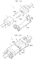
- FIG. 1(a) and Fig. 1(b) show an overall configuration of a multicore optical connector according to an embodiment of the present invention in which Fig 1(a) represents a non-connected state and Fig 1(b) represents a connected state.
- a multicore optical connector 1 is constituted by a pair of ferrules 2 and a coupling member 3.
- the pair of ferrules 2 is a pair of a same ferrule, and the ferrules 2 are vertically flipped to face each other so that end faces 2A are parallel to each other.
- the coupling member 3 is constituted by a guide pin 3A and a clamp spring 3B in this example, however, the configuration of the coupling member 3 is not limited to this, and the coupling member 3 may be an adapter or the like which holds the pair of ferrules 2.
- a plurality of optical fibers with lenses 4 are arranged and held in the ferrules 2, and the end faces 2A of the ferrules 2 are inclined by a set angle relative to a central axis of the ferrules 2.
- the coupling member 3 coaxially couples the ferrules 2 in a non-contact state so that the inclined end faces 2A are separated from each other by a set distance.
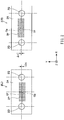
- a hole 2P that holds an optical fiber with lens is formed in plurality in two directions (an X direction and a Y direction in the diagram) that are perpendicular to a direction of a central axis Of (a Z direction in the diagram) of the ferrules 2.
- the holes 2P are arranged in m-number of rows (12 rows) in a horizontal direction (the X direction) and in n-number of rows (4 rows) in a vertical direction (the Y direction), and a center of arrangement (an arrangement central axis) Op of the holes 2P is eccentric by ⁇ t in the Y direction in the diagram relative to the central axis Of of the ferrules 2.
- the ferrules 2 are provided with a pair of guide holes 2Q.
- the guide holes 2Q coaxially couple the pair of ferrules 2 when the guide pin 3A is inserted therein and are formed at positions that are vertically and horizontally symmetrical relative to the central axis Of of the ferrules 2.
- An inclination direction of the end face 2A of the ferrules 2 is consistent with a direction of eccentricity of the center of arrangement (the arrangement central axis) Op.
- the direction of eccentricity of the center of arrangement Op and the inclination direction of the end face 2A are a +Y direction in the diagram
- the direction of eccentricity of the center of arrangement Op and the inclination direction of the end face 2A are a -Y direction in the diagram.
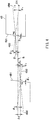
- a GRIN lens 4B is fused to a tip of an optical fiber 4A, and an end face of the GRIN lens 4B is inclined along the end face 2A of the ferrules 2 so that the optical fibers with lenses 4 are optically coupled to each other.
- fusing positions 4F between the GRIN lens 4B and the optical fiber 4A are arranged so as to be inclined along the end face 2A.
- an inclination angle of the end face 2A (an inclination angle relative to the Y direction) is ⁇ 0
- a straight line connecting the fusing positions 4F of the optical fibers with lenses 4 arranged in the Y direction is inclined by an angle of ⁇ 0 relative to the Y direction.
- the angle ⁇ 0 may be 4 degrees or more, favorably 6 degrees or more, and more favorably 8 degrees or more.
- the ferrules 2 holding the optical fiber with lens 4 as described above each have the inclined end face 2A, and in all of the held optical fibers with lenses 4, a lens length L0 of the GRIN lenses 4B is the same. Accordingly, all of the optical fibers with lenses 4 held by the ferrules 2 assume a same optically coupled state by vertically flipping and connecting a pair of the ferrules 2, and by setting an appropriate end face interval relative to the inclination angle ⁇ 0 of the end face 2A, all of the optical fibers with lenses 4 are able to realize low-loss optical coupling with coinciding beam waist positions.
- Fig. 4 shows a coupled state of each optical fiber with lens 4.
- the GRIN lens 4B having an inclined end face 4B1 (“4B2" in the diagram denotes a perpendicular to the inclined end face 4B1) is coupled by eccentrically moving the GRIN lens 4B in the inclination direction by ⁇ t, light passing a central axis 4B0 of the GRIN lens 4B is emitted in a direction of an angle ⁇ f relative to the central axis 4B0.
- the ferrule 2 can be formed by insert molding using a mold in which a pin for forming the holes 2P and the guide hole 2Q is positioned. By appropriately eccentrically moving the position of the pin relative to a center of the mold, a ferrule 2 can be formed in which the center of arrangement Op of the large number of rows of the holes 2P is eccentric by ⁇ t relative to the central axis Of.
- Fig. 5 shows an example of a step of fixing the optical fiber with lens 4 to the ferrule 2 and a step of polishing an end face of the ferrule 2 to form an inclined end face.
- the GRIN lenses 4B all of which having a same length Ls, are fused to the optical fibers 4A.
- fusing positions 4F are arranged so as to be inclined by providing differences in amounts of protrusion (h1, h2, h3, and h4) by which the GRIN lenses 4B protrude from end faces 2S of the ferrules 2 prior to polishing.
- an inclination angle of a straight line connecting the fusing positions 4F is set to ⁇ 0 by appropriately setting the amounts of protrusion (h1, h2, h3, and h4).
- the optical fiber with lens 4 inserted into the hole 2P is fixed to the ferrule 2.
- the end face 2S and the GRIN lens 4B protruding from the end face 2S are polished.
- the inclined end face 2A is formed and, at the same time, the inclined end face 4B1 of the GRIN lens 4B is formed.
- An amount of polishing at this point is set so that a lens length of the GRIN lens 4B equals the set lens length L0.
- Fig. 6 shows another example of the step of fixing the optical fiber with lens 4 to the ferrule 2 and the step of polishing an end face of the ferrule 2 to form an inclined end face.
- the lengths of the GRIN lenses 4B are set to different lengths (LI, L2, L3, and L4).
- the fusing positions 4F are arranged so as to be inclined.
- an inclination angle of a straight line connecting the fusing positions 4F is set to ⁇ 0 by appropriately setting the lengths (LI, L2, L3, and L4) of the GRIN lenses 4B.
- the optical fiber with lens 4 inserted into the hole 2P is fixed to the ferrule 2.
- the end face 2S and the GRIN lens 4B are polished.
- the inclined end face 2A is formed and, at the same time, the inclined end face 4B1 of the GRIN lens 4B is formed.
- An amount of polishing at this point is set so that a lens length of the GRIN lens 4B equals the set lens length L0.
- the multicore optical connector 1 including the ferrule 2 which holds the optical fiber with lens 4 configured as described above, by inclining an end face of the GRIN lens 4B of the optical fiber with lens 4 relative to the central axis Of of the ferrule 2, reflection return light can be reduced and, at the same time, inverse incidence of reflection return light to the optical fiber 4A can be suppressed.
- multicore connector connection of optical fibers with lenses 4 can be performed while keeping a lens length L0 of the GRIN lenses 4B constant. Accordingly, in the multicore optical connector 1 in which a plurality of optical fibers with lenses 4 are arranged and held in the ferrule 2, reflection return light can be suppressed and low-loss connection can be performed.
Landscapes
- Physics & Mathematics (AREA)
- General Physics & Mathematics (AREA)
- Optics & Photonics (AREA)
- Engineering & Computer Science (AREA)
- Plasma & Fusion (AREA)
- Optical Couplings Of Light Guides (AREA)
- Mechanical Coupling Of Light Guides (AREA)
Abstract
Description
- The present invention relates to a multicore optical connector and a method of manufacturing the same.
- Optical interconnection is attracting attention as technology for achieving higher speed, larger capacity, and lower power consumption in information transmission. Important element technology in optical interconnection is connection technology of optical wiring, and connections that are simple but provide high coupling efficiency are required not only for connecting optical fibers with each other but also for connecting optical wiring between boards, between chips, and within chips.
- In connections of optical wiring, a connector connection using a connecting terminal called a ferrule is generally known, and configuring connectors to have multiple cores is essential in realizing connections of high-density optical wiring. As a conventional multicore optical connector, a known multicore optical connector is provided with: ferrules having positioning holes in which a plurality of end portions of optical fibers are arranged and a pair of guide holes into which guide pins are to be inserted; and the guide pins which are inserted into the guide holes of the ferrules to coaxially connect a pair of the ferrules (refer to
PTL 1 below). - Meanwhile, an optical fiber with lens (an optical fiber collimator) in which a GRIN lens (a gradient index lens) is fused to a tip of an optical fiber is known (refer to
PTL 2 below). A connection of optical wiring using an optical fiber with lens has features that enables energy density of emitted light to be reduced due to beam expansion by a GRIN lens and, at the same time, enables connecting end faces to be mutually contactless. When the energy density of emitted light is reduced, a phenomenon where a connecting end face or an interior of an optical fiber is damaged by generation of heat caused by energy concentrating on a foreign object adhered to an end face, a fiber fuse associated with the generation of heat, or the like can be avoided, and further by making the connecting end faces contactless, optical coupling can be performed even when a foreign object is present on a connecting end face and the trouble of cleaning the connecting end face or the like can be spared. Furthermore, in a connector connection, making connecting end faces contactless prevents scuffing or defects from occurring on a ferrule end face. -
- [PTL 1] Japanese Patent Application Laid-open No.
2004-219944 - [PTL 2] Japanese Patent Application Laid-open No.
2009-47993 - In the connection of optical wiring using an optical fiber with lens, making an end face of a GRIN lens contactless causes the end face to act as an interface between the GRIN lens (a high-refractive index layer) and air (a low-refractive index layer), and reflection return light on the end face becomes conspicuous. Since the reflection return light is collected by the GRIN lens and is inversely incident to the optical fiber, the reflection return light not only increases transmission loss but also has an adverse effect on a light source and the like.
- In order to address this issue, reflection return light can be reduced and inverse incidence of reflection return light to the optical fiber can be prevented by inclining an end face of the GRIN lens relative to a central axis of the GRIN lens or the optical fiber. However, in accordance with Snell's law, since inclining the end face of the GRIN lens causes an optical axis of coupled light to have a prescribed angle relative to the central axis of the GRIN lens, when connecting a pair of ferrules using a multicore optical connector by coaxially butting the ferrules against each other, optical coupling cannot be performed if a central axis of the ferrules and a center of arrangement of GRIN lenses match each other.
- In addition, in a case where a plurality of GRIN lenses are arranged along an inclination direction of the end faces of the GRIN lenses, there is a problem in that a difference is created among lens lengths of the GRIN lenses depending on arrangement positions when polishing an end face of a ferrule to form an inclined end face, which makes it difficult to perform a connection with low loss so that beam waist positions of coupled light coincide in all optical fibers with lenses.
- The present invention has been proposed in order to cope with such situations. Specifically, an object of the present invention is, for example, to enable, in a multicore optical connector in which a plurality of optical fibers with lenses are arranged and held in a ferrule, reflection return light to be suppressed and low-loss connection to be performed.
- In order to solve the problems described above, a multicore optical connector and a method of manufacturing the same according to the present invention are configured as follows.
- A multicore optical connector, including: a ferrule in which a plurality of optical fibers with lenses are arranged and held, the optical fibers with lenses having GRIN lenses fused to tips of optical fibers; and a coupling member which couples a pair of the ferrules so that the ferrules oppose each other in a non-contact state and end faces of the ferrules are parallel to each other, wherein the ferrules each have the end face inclined by a set angle relative to a central axis, and the GRIN lenses are arranged and held parallel to the central axis so that a center of arrangement is at a position eccentric relative to the central axis, and the optical fibers with lenses held by the pair of the ferrules have end faces of the GRIN lenses inclined along the end faces of the ferrules so that the optical fibers with lenses are optically coupled to each other, and in the optical fibers with lenses arranged in an inclination direction of the end faces of the ferrules, fusing positions between the GRIN lenses and the optical fibers are arranged so as to be inclined along the end faces.
- A method of manufacturing a multicore optical connector including a ferrule in which a plurality of optical fibers with lenses are arranged and held, the optical fibers with lenses having GRIN lenses fused to tips of optical fibers, and a coupling member which couples a pair of the ferrules so that the ferrules oppose each other in a non-contact state and end faces of the ferrules are parallel to each other, the method including: a step of molding each of the ferrules in which a plurality of holes along a central axis of the ferrule are arranged so that a center of arrangement is eccentric relative to the central axis; a step of inserting the optical fibers with lenses into the holes, arranging fusing positions between the GRIN lenses and the optical fibers so as to be inclined by a set angle relative to the central axis, and fixing the optical fibers with lenses to the ferrules; and a step of polishing the end faces of the ferrules so that a direction of inclined arrangement of the fusing positions is parallel to the end faces.
- According to the multicore optical connector and the method of manufacturing the same described above, by inclining an end face of a GRIN lens of an optical fiber with lens relative to a central axis of a ferrule, reflection return light can be reduced and, at the same time, inverse incidence of reflection return light to an optical fiber can be suppressed. In addition, by arranging a fusing position between the GRIN lens and the optical fiber so as to be inclined along an inclination of an end face of the ferrule, multicore connector connection of optical fibers with lenses can be performed while keeping a lens length of the GRIN lens constant. Accordingly, in a multicore optical connector in which a plurality of optical fibers with lenses are arranged and held in a ferrule, reflection return light can be suppressed and low-loss connection can be performed.
-
-
Fig. 1(a) and Fig. 1(b) are explanatory diagrams showing an overall configuration of a multicore optical connector according to an embodiment of the present invention (in whichFig 1(a) represents a non-connected state andFig 1(b) represents a connected state). -
Fig. 2 is a front view of a ferrule in a multicore optical connector according to an embodiment of the present invention. -
Fig. 3 is an explanatory diagram showing a pair of ferrules holding optical fibers with lenses. -
Fig. 4 is an explanatory diagram showing a coupled state of each optical fiber with lens. -
Fig. 5 is an explanatory diagram showing a method of manufacturing a multicore optical connector (first example) according to an embodiment of the present invention. -
Fig. 6 is an explanatory diagram showing a method of manufacturing a multicore optical connector (second example) according to an embodiment of the present invention. - Hereinafter, an embodiment of the present invention will be described with reference to the drawings.
Fig. 1(a) and Fig. 1(b) show an overall configuration of a multicore optical connector according to an embodiment of the present invention in whichFig 1(a) represents a non-connected state andFig 1(b) represents a connected state. A multicoreoptical connector 1 is constituted by a pair offerrules 2 and acoupling member 3. The pair offerrules 2 is a pair of a same ferrule, and theferrules 2 are vertically flipped to face each other so thatend faces 2A are parallel to each other. Thecoupling member 3 is constituted by aguide pin 3A and aclamp spring 3B in this example, however, the configuration of thecoupling member 3 is not limited to this, and thecoupling member 3 may be an adapter or the like which holds the pair offerrules 2. - A plurality of optical fibers with
lenses 4 are arranged and held in theferrules 2, and the end faces 2A of theferrules 2 are inclined by a set angle relative to a central axis of theferrules 2. Thecoupling member 3 coaxially couples theferrules 2 in a non-contact state so that theinclined end faces 2A are separated from each other by a set distance. - As shown in
Fig. 2 , in the ferrules 2 (in the diagram, a right-side ferrule is denoted as 2(R) and a left-side ferrule is denoted as 2(L)), ahole 2P that holds an optical fiber with lens is formed in plurality in two directions (an X direction and a Y direction in the diagram) that are perpendicular to a direction of a central axis Of (a Z direction in the diagram) of theferrules 2. In the illustrated example, theholes 2P are arranged in m-number of rows (12 rows) in a horizontal direction (the X direction) and in n-number of rows (4 rows) in a vertical direction (the Y direction), and a center of arrangement (an arrangement central axis) Op of theholes 2P is eccentric by Δt in the Y direction in the diagram relative to the central axis Of of theferrules 2. In addition, theferrules 2 are provided with a pair ofguide holes 2Q. Theguide holes 2Q coaxially couple the pair offerrules 2 when theguide pin 3A is inserted therein and are formed at positions that are vertically and horizontally symmetrical relative to the central axis Of of theferrules 2. - An inclination direction of the
end face 2A of theferrules 2 is consistent with a direction of eccentricity of the center of arrangement (the arrangement central axis) Op. In other words, in the case of the right-side ferrule 2(R) in the diagram, the direction of eccentricity of the center of arrangement Op and the inclination direction of theend face 2A are a +Y direction in the diagram, and in the case of the left-side ferrule 2(L) in the diagram, the direction of eccentricity of the center of arrangement Op and the inclination direction of theend face 2A are a -Y direction in the diagram. - As shown in
Fig. 3 , in the optical fiber withlens 4 held by theferrules 2, aGRIN lens 4B is fused to a tip of anoptical fiber 4A, and an end face of theGRIN lens 4B is inclined along theend face 2A of theferrules 2 so that the optical fibers withlenses 4 are optically coupled to each other. In addition, in the optical fibers withlenses 4 arranged in the inclination direction (the Y direction in the diagram) of theend faces 2A of theferrules 2,fusing positions 4F between theGRIN lens 4B and theoptical fiber 4A are arranged so as to be inclined along theend face 2A. In other words, when an inclination angle of theend face 2A (an inclination angle relative to the Y direction) is θ0, a straight line connecting thefusing positions 4F of the optical fibers withlenses 4 arranged in the Y direction is inclined by an angle of θ0 relative to the Y direction. Specifically, the angle θ0 may be 4 degrees or more, favorably 6 degrees or more, and more favorably 8 degrees or more. - The
ferrules 2 holding the optical fiber withlens 4 as described above each have theinclined end face 2A, and in all of the held optical fibers withlenses 4, a lens length L0 of theGRIN lenses 4B is the same. Accordingly, all of the optical fibers withlenses 4 held by theferrules 2 assume a same optically coupled state by vertically flipping and connecting a pair of theferrules 2, and by setting an appropriate end face interval relative to the inclination angle θ0 of theend face 2A, all of the optical fibers withlenses 4 are able to realize low-loss optical coupling with coinciding beam waist positions. -
Fig. 4 shows a coupled state of each optical fiber withlens 4. When theGRIN lens 4B having an inclined end face 4B1 ("4B2" in the diagram denotes a perpendicular to the inclined end face 4B1) is coupled by eccentrically moving theGRIN lens 4B in the inclination direction by Δt, light passing a central axis 4B0 of theGRIN lens 4B is emitted in a direction of an angle θf relative to the central axis 4B0. In order to set a center of optical coupling S of light emitted from oneGRIN lens 4B and incident to anotherGRIN lens 4B at a beam waist position, when a beam waist distance is denoted by W, a central refractive index of theGRIN lens 4B is denoted by ng, and the inclination angle of the inclined end face 4B1 is denoted by θ0, a relationship expressed by (1) below is satisfied in accordance with Snell's law (given that a space between end faces has a refractive index of 1) and, at the same time, a relationship among an emission angle θf, an amount of eccentricity Δt, and the beam waist distance (a center distance of space) W is expressed by (2) below. The expressions (1) and (2) below enable an amount of eccentricity Δt and the inclination angle θ0 of the end face to be appropriately designed.

- A method of manufacturing such a multicore optical connector will now be described. The
ferrule 2 can be formed by insert molding using a mold in which a pin for forming theholes 2P and theguide hole 2Q is positioned. By appropriately eccentrically moving the position of the pin relative to a center of the mold, aferrule 2 can be formed in which the center of arrangement Op of the large number of rows of theholes 2P is eccentric by Δt relative to the central axis Of. -
Fig. 5 shows an example of a step of fixing the optical fiber withlens 4 to theferrule 2 and a step of polishing an end face of theferrule 2 to form an inclined end face. In this example, in the optical fiber withlens 4 prior to fixing, theGRIN lenses 4B, all of which having a same length Ls, are fused to theoptical fibers 4A. When fixing the optical fiber withlens 4 to theferrule 2, fusingpositions 4F are arranged so as to be inclined by providing differences in amounts of protrusion (h1, h2, h3, and h4) by which theGRIN lenses 4B protrude from end faces 2S of theferrules 2 prior to polishing. In this case, an inclination angle of a straight line connecting the fusingpositions 4F is set to θ0 by appropriately setting the amounts of protrusion (h1, h2, h3, and h4). In this state, the optical fiber withlens 4 inserted into thehole 2P is fixed to theferrule 2. - Next, the
end face 2S and theGRIN lens 4B protruding from theend face 2S are polished. By this polishing, theinclined end face 2A is formed and, at the same time, the inclined end face 4B1 of theGRIN lens 4B is formed. An amount of polishing at this point is set so that a lens length of theGRIN lens 4B equals the set lens length L0. -
Fig. 6 shows another example of the step of fixing the optical fiber withlens 4 to theferrule 2 and the step of polishing an end face of theferrule 2 to form an inclined end face. In this example, in the optical fiber withlens 4 prior to fixing, the lengths of theGRIN lenses 4B are set to different lengths (LI, L2, L3, and L4). In addition, by arranging the end faces of theGRIN lenses 4B with the different lengths so as to be flush with theend face 2S of theferrule 2 prior to polishing, the fusingpositions 4F are arranged so as to be inclined. In this case, an inclination angle of a straight line connecting the fusingpositions 4F is set to θ0 by appropriately setting the lengths (LI, L2, L3, and L4) of theGRIN lenses 4B. In this state, the optical fiber withlens 4 inserted into thehole 2P is fixed to theferrule 2. - Next, the
end face 2S and theGRIN lens 4B are polished. By this polishing, theinclined end face 2A is formed and, at the same time, the inclined end face 4B1 of theGRIN lens 4B is formed. An amount of polishing at this point is set so that a lens length of theGRIN lens 4B equals the set lens length L0. - With the multicore
optical connector 1 including theferrule 2 which holds the optical fiber withlens 4 configured as described above, by inclining an end face of theGRIN lens 4B of the optical fiber withlens 4 relative to the central axis Of of theferrule 2, reflection return light can be reduced and, at the same time, inverse incidence of reflection return light to theoptical fiber 4A can be suppressed. In addition, by arrangingfusing positions 4F between theGRIN lenses 4B and theoptical fibers 4A so as to be inclined along an inclination of an end face of theferrule 2, multicore connector connection of optical fibers withlenses 4 can be performed while keeping a lens length L0 of theGRIN lenses 4B constant. Accordingly, in the multicoreoptical connector 1 in which a plurality of optical fibers withlenses 4 are arranged and held in theferrule 2, reflection return light can be suppressed and low-loss connection can be performed. - While embodiments of the present invention have been described in detail with reference to the drawings, it is to be understood that specific configurations of the present invention are not limited to the embodiments and that various design modifications and the like may be made without departing from the spirit and scope of the invention. In addition, the embodiments described above may be implemented so as to combine respective techniques as long as there are no contradictions, problems, and the like in an object, a configuration, and the like of such implementations.
-
- 1
- Multicore optical connector
- 2
- Ferrule
- 2A
- End face
- 2P
- Hole
- 2Q
- Guide hole
- 3
- Coupling member
- 3A
- Guide pin
- 3B
- Clamp spring
- 4
- Optical fiber with lens
- 4A
- Optical fiber
- 4B
- GRIN lens
Claims (4)
- A multicore optical connector, comprising: a ferrule in which a plurality of optical fibers with lenses are arranged and held, said optical fibers with lenses having GRIN lenses fused to tips of optical fibers; and a coupling member which couples a pair of said ferrules so that said ferrules oppose each other in a non-contact state and end faces of said ferrules are parallel to each other, wherein
said ferrules each have said end face inclined by a set angle relative to a central axis, and said GRIN lenses are arranged and held parallel to said central axis so that a center of arrangement is at a position eccentric relative to said central axis, and
said optical fibers with lenses held by the pair of said ferrules have end faces of said GRIN lenses inclined along said end faces of said ferrules so that said optical fibers with lenses are optically coupled to each other, and in said optical fibers with lenses arranged in an inclination direction of said end faces of said ferrules, fusing positions between said GRIN lenses and said optical fibers are arranged so as to be inclined along said end faces. - A method of manufacturing a multicore optical connector including a ferrule in which a plurality of optical fibers with lenses are arranged and held, said optical fibers with lenses having GRIN lenses fused to tips of optical fibers, and a coupling member which couples a pair of said ferrules so that said ferrules oppose each other in a non-contact state and end faces of said ferrules are parallel to each other, the method comprising:a step of molding each of said ferrules in which a plurality of holes along a central axis of said ferrule are arranged so that a center of arrangement is eccentric relative to said central axis;a step of inserting said optical fibers with lenses into said holes, arranging fusing positions between said GRIN lenses and said optical fibers so as to be inclined by a set angle relative to said central axis, and fixing said optical fibers with lenses to said ferrules; anda step of polishing said end faces of said ferrules so that a direction of inclined arrangement of said fusing positions is parallel to said end faces.
- The method of manufacturing a multicore optical connector according to claim 2, wherein said fusing positions are arranged so as to be inclined by providing differences in amounts of protrusion by which said GRIN lenses protrude from said end faces of said ferrules prior to polishing.
- The method of manufacturing a multicore optical connector according to claim 2, wherein said fusing positions are arranged so as to be inclined by arranging end faces of said GRIN lenses with different lengths so as to be flush with said end faces of said ferrules prior to polishing.
Applications Claiming Priority (2)
| Application Number | Priority Date | Filing Date | Title |
|---|---|---|---|
| JP2016116204A JP2017219801A (en) | 2016-06-10 | 2016-06-10 | Multicore optical connector and manufacturing method therefor |
| PCT/JP2017/017480 WO2017212845A1 (en) | 2016-06-10 | 2017-05-09 | Multicore optical connector and method for manufacturing same |
Publications (2)
| Publication Number | Publication Date |
|---|---|
| EP3470897A1 true EP3470897A1 (en) | 2019-04-17 |
| EP3470897A4 EP3470897A4 (en) | 2020-01-15 |
Family
ID=60578548
Family Applications (1)
| Application Number | Title | Priority Date | Filing Date |
|---|---|---|---|
| EP17810027.7A Pending EP3470897A4 (en) | 2016-06-10 | 2017-05-09 | MULTIPLE CORE OPTICAL CONNECTOR AND MANUFACTURING METHOD THEREOF |
Country Status (5)
| Country | Link |
|---|---|
| US (1) | US10613277B2 (en) |
| EP (1) | EP3470897A4 (en) |
| JP (1) | JP2017219801A (en) |
| CN (1) | CN109196398A (en) |
| WO (1) | WO2017212845A1 (en) |
Families Citing this family (7)
| Publication number | Priority date | Publication date | Assignee | Title |
|---|---|---|---|---|
| JP6597439B2 (en) * | 2016-03-24 | 2019-10-30 | 住友電気工業株式会社 | Optical connector ferrule, optical connector and optical coupling structure |
| JP2017219801A (en) * | 2016-06-10 | 2017-12-14 | 東洋製罐グループホールディングス株式会社 | Multicore optical connector and manufacturing method therefor |
| JP7120306B2 (en) * | 2018-06-20 | 2022-08-17 | 住友電気工業株式会社 | Optical connection parts, optical connectors and optical connection structures |
| CN110601767A (en) * | 2019-09-19 | 2019-12-20 | 深圳市深光谷科技有限公司 | Transmit-receive integrated optical module, device and system |
| CN110568550B (en) * | 2019-09-24 | 2020-10-09 | 广州宏晟光电科技股份有限公司 | Shape forming method of optical fiber image inverter |
| JP7352464B2 (en) * | 2019-12-26 | 2023-09-28 | 株式会社フジクラ | Multicore fibers, fiber optic cables, and optical connectors |
| JP7601369B2 (en) * | 2020-11-13 | 2024-12-17 | 湖北工業株式会社 | Optical Filter Device |
Family Cites Families (23)
| Publication number | Priority date | Publication date | Assignee | Title |
|---|---|---|---|---|
| US4962988A (en) * | 1989-07-10 | 1990-10-16 | Optomec Design Company | Termination interface structure and method for joining an optical fiber to a graded index rod lens |
| AU635172B2 (en) * | 1991-05-13 | 1993-03-11 | Nippon Telegraph & Telephone Corporation | Multifiber optical connector plug with low reflection and low insertion loss |
| JPH0572444A (en) * | 1991-09-17 | 1993-03-26 | Fujitsu Ltd | Multifiber optical connector |
| FR2754630B1 (en) * | 1996-10-10 | 2000-12-01 | Electricite De France | METHOD FOR MANUFACTURING A CONDUCTOR, OR ELECTRICAL CIRCUIT COMPENSATED WITH RADIOELECTRIC PARASITES SUCH AS MICRO-DISCHARGES AND CORRESPONDING CONDUCTOR OR CIRCUIT |
| US6012852A (en) * | 1996-12-18 | 2000-01-11 | The Whitaker Corporation | Expanded beam fiber optic connector |
| US6542665B2 (en) * | 2001-02-17 | 2003-04-01 | Lucent Technologies Inc. | GRIN fiber lenses |
| US6655850B2 (en) * | 2001-07-05 | 2003-12-02 | Corning Incorporated | Hybrid fiber expanded beam connector and methods for using and making the hybrid fiber expanded beam connector |
| JP3764424B2 (en) | 2003-01-17 | 2006-04-05 | 株式会社東芝 | Multi-core optical connector |
| JP2006235245A (en) * | 2005-02-24 | 2006-09-07 | Kyocera Corp | Ferrule-type optical components and optical modules using the same |
| JP4925323B2 (en) * | 2007-08-21 | 2012-04-25 | 東洋ガラス株式会社 | Optical fiber collimator and optical fiber collimator array manufacturing method |
| WO2013086117A2 (en) * | 2011-12-09 | 2013-06-13 | Corning Cable Systems Llc | Gradient index (grin) lens holders employing groove alignment features(s) in recessed cover and single piece components, connectors, and methods |
| TWI506313B (en) * | 2011-12-27 | 2015-11-01 | Hon Hai Prec Ind Co Ltd | Optical fiber connector device |
| TWI557455B (en) * | 2012-05-16 | 2016-11-11 | 鴻海精密工業股份有限公司 | Fiber connector assembly |
| JP5377730B1 (en) | 2012-08-31 | 2013-12-25 | 株式会社フジクラ | Manufacturing method of optical fiber array |
| US9946033B2 (en) * | 2013-08-07 | 2018-04-17 | Corning Optical Communications LLC | Fiber optic connector with adhesive management |
| JP6379898B2 (en) * | 2014-09-11 | 2018-08-29 | 住友電気工業株式会社 | Optical connector and optical connector manufacturing method |
| JP6459334B2 (en) * | 2014-09-18 | 2019-01-30 | 住友電気工業株式会社 | Ferrule and optical connection structure |
| WO2016084113A1 (en) * | 2014-11-26 | 2016-06-02 | オリンパス株式会社 | Optical fiber connection mechanism and optical fiber connection method |
| US9645325B2 (en) * | 2015-05-01 | 2017-05-09 | Corning Optical Communications LLC | Expanded-beam ferrule with high coupling efficiency for optical interface devices |
| US9739948B2 (en) * | 2015-12-28 | 2017-08-22 | Sumitomo Electric Industries, Ltd. | Lens-equipped connector |
| JP6878770B2 (en) * | 2016-04-05 | 2021-06-02 | 東洋製罐グループホールディングス株式会社 | Optical fiber with lens and optical coupler |
| JP2017219801A (en) * | 2016-06-10 | 2017-12-14 | 東洋製罐グループホールディングス株式会社 | Multicore optical connector and manufacturing method therefor |
| JP2018194669A (en) * | 2017-05-17 | 2018-12-06 | コニカミノルタ株式会社 | Optical element and optical connector |
-
2016
- 2016-06-10 JP JP2016116204A patent/JP2017219801A/en active Pending
-
2017
- 2017-05-09 WO PCT/JP2017/017480 patent/WO2017212845A1/en not_active Ceased
- 2017-05-09 EP EP17810027.7A patent/EP3470897A4/en active Pending
- 2017-05-09 CN CN201780033411.2A patent/CN109196398A/en active Pending
- 2017-05-09 US US16/307,392 patent/US10613277B2/en active Active
Also Published As
| Publication number | Publication date |
|---|---|
| US20190219773A1 (en) | 2019-07-18 |
| JP2017219801A (en) | 2017-12-14 |
| EP3470897A4 (en) | 2020-01-15 |
| US10613277B2 (en) | 2020-04-07 |
| WO2017212845A1 (en) | 2017-12-14 |
| CN109196398A (en) | 2019-01-11 |
Similar Documents
| Publication | Publication Date | Title |
|---|---|---|
| EP3470897A1 (en) | Multicore optical connector and method for manufacturing same | |
| EP2998771B1 (en) | Ferrule | |
| US8360659B2 (en) | Fiber-optic pin-and-socket connector having a beam expansion device | |
| JP6379898B2 (en) | Optical connector and optical connector manufacturing method | |
| US9897763B2 (en) | Transceiver interface having staggered cleave positions | |
| US10365439B2 (en) | Optical interconnect | |
| CN104169765B (en) | Use groove alignment feature structure and graded index (GRIN) lens mount on total internal reflection (TIR) surface and associated component, adapter and method | |
| EP3734338B1 (en) | Connection device, optical connector manufacturing device, connection method, and method for manufacturing optical connector | |
| CN105607194B (en) | Adapter and optical conenctor coupled system | |
| US20150301295A1 (en) | Multi-channel optical connector with coupling lenses | |
| JP6806059B2 (en) | Fiber optic connector with lens | |
| US20140294339A1 (en) | Compact optical fiber splitters | |
| CN105452922B (en) | Optical Couplers for Multicore Fibers | |
| CN112305678B (en) | Optical connector | |
| CN108351478A (en) | Optical connector and optical coupling construction | |
| US9618711B2 (en) | Apparatus for forming a transceiver interface, ferrule, and optical transceiver component | |
| US10775569B2 (en) | Optical connector and optical connection structure | |
| TW201831933A (en) | Optical connection component and optical coupling structure | |
| CN2557964Y (en) | Multi-light path alignment device | |
| CN107305270A (en) | Compact optical fiber shunt | |
| JP2016057483A (en) | Connector ferrule | |
| US20230273376A1 (en) | Optical connection component and connector assembly | |
| CN108474916A (en) | Optical receptacle, optical module and assay method |
Legal Events
| Date | Code | Title | Description |
|---|---|---|---|
| STAA | Information on the status of an ep patent application or granted ep patent |
Free format text: STATUS: THE INTERNATIONAL PUBLICATION HAS BEEN MADE |
|
| PUAI | Public reference made under article 153(3) epc to a published international application that has entered the european phase |
Free format text: ORIGINAL CODE: 0009012 |
|
| STAA | Information on the status of an ep patent application or granted ep patent |
Free format text: STATUS: REQUEST FOR EXAMINATION WAS MADE |
|
| 17P | Request for examination filed |
Effective date: 20181130 |
|
| AK | Designated contracting states |
Kind code of ref document: A1 Designated state(s): AL AT BE BG CH CY CZ DE DK EE ES FI FR GB GR HR HU IE IS IT LI LT LU LV MC MK MT NL NO PL PT RO RS SE SI SK SM TR |
|
| AX | Request for extension of the european patent |
Extension state: BA ME |
|
| DAV | Request for validation of the european patent (deleted) | ||
| DAX | Request for extension of the european patent (deleted) | ||
| A4 | Supplementary search report drawn up and despatched |
Effective date: 20191218 |
|
| RIC1 | Information provided on ipc code assigned before grant |
Ipc: G02B 6/38 20060101ALI20191212BHEP Ipc: G02B 6/32 20060101AFI20191212BHEP Ipc: G02B 6/40 20060101ALI20191212BHEP Ipc: G02B 6/255 20060101ALI20191212BHEP |
|
| STAA | Information on the status of an ep patent application or granted ep patent |
Free format text: STATUS: EXAMINATION IS IN PROGRESS |
|
| 17Q | First examination report despatched |
Effective date: 20211206 |
|
| STAA | Information on the status of an ep patent application or granted ep patent |
Free format text: STATUS: THE APPLICATION HAS BEEN WITHDRAWN |