EP3470688B1 - Affixing device for pieces - Google Patents
Affixing device for pieces Download PDFInfo
- Publication number
- EP3470688B1 EP3470688B1 EP18382670.0A EP18382670A EP3470688B1 EP 3470688 B1 EP3470688 B1 EP 3470688B1 EP 18382670 A EP18382670 A EP 18382670A EP 3470688 B1 EP3470688 B1 EP 3470688B1
- Authority
- EP
- European Patent Office
- Prior art keywords
- affixing
- pieces
- affixing device
- retaining
- accommodation space
- Prior art date
- Legal status (The legal status is an assumption and is not a legal conclusion. Google has not performed a legal analysis and makes no representation as to the accuracy of the status listed.)
- Not-in-force
Links
Images

Classifications
-
- F—MECHANICAL ENGINEERING; LIGHTING; HEATING; WEAPONS; BLASTING
- F16—ENGINEERING ELEMENTS AND UNITS; GENERAL MEASURES FOR PRODUCING AND MAINTAINING EFFECTIVE FUNCTIONING OF MACHINES OR INSTALLATIONS; THERMAL INSULATION IN GENERAL
- F16B—DEVICES FOR FASTENING OR SECURING CONSTRUCTIONAL ELEMENTS OR MACHINE PARTS TOGETHER, e.g. NAILS, BOLTS, CIRCLIPS, CLAMPS, CLIPS OR WEDGES; JOINTS OR JOINTING
- F16B13/00—Dowels or other devices fastened in walls or the like by inserting them in holes made therein for that purpose
- F16B13/04—Dowels or other devices fastened in walls or the like by inserting them in holes made therein for that purpose with parts gripping in the hole or behind the reverse side of the wall after inserting from the front
-
- F—MECHANICAL ENGINEERING; LIGHTING; HEATING; WEAPONS; BLASTING
- F16—ENGINEERING ELEMENTS AND UNITS; GENERAL MEASURES FOR PRODUCING AND MAINTAINING EFFECTIVE FUNCTIONING OF MACHINES OR INSTALLATIONS; THERMAL INSULATION IN GENERAL
- F16B—DEVICES FOR FASTENING OR SECURING CONSTRUCTIONAL ELEMENTS OR MACHINE PARTS TOGETHER, e.g. NAILS, BOLTS, CIRCLIPS, CLAMPS, CLIPS OR WEDGES; JOINTS OR JOINTING
- F16B5/00—Joining sheets or plates, e.g. panels, to one another or to strips or bars parallel to them
- F16B5/02—Joining sheets or plates, e.g. panels, to one another or to strips or bars parallel to them by means of fastening members using screw-thread
- F16B5/025—Joining sheets or plates, e.g. panels, to one another or to strips or bars parallel to them by means of fastening members using screw-thread specially designed to compensate for misalignement or to eliminate unwanted play
-
- F—MECHANICAL ENGINEERING; LIGHTING; HEATING; WEAPONS; BLASTING
- F16—ENGINEERING ELEMENTS AND UNITS; GENERAL MEASURES FOR PRODUCING AND MAINTAINING EFFECTIVE FUNCTIONING OF MACHINES OR INSTALLATIONS; THERMAL INSULATION IN GENERAL
- F16B—DEVICES FOR FASTENING OR SECURING CONSTRUCTIONAL ELEMENTS OR MACHINE PARTS TOGETHER, e.g. NAILS, BOLTS, CIRCLIPS, CLAMPS, CLIPS OR WEDGES; JOINTS OR JOINTING
- F16B4/00—Shrinkage connections, e.g. assembled with the parts at different temperature; Force fits; Non-releasable friction-grip fastenings
-
- F—MECHANICAL ENGINEERING; LIGHTING; HEATING; WEAPONS; BLASTING
- F16—ENGINEERING ELEMENTS AND UNITS; GENERAL MEASURES FOR PRODUCING AND MAINTAINING EFFECTIVE FUNCTIONING OF MACHINES OR INSTALLATIONS; THERMAL INSULATION IN GENERAL
- F16B—DEVICES FOR FASTENING OR SECURING CONSTRUCTIONAL ELEMENTS OR MACHINE PARTS TOGETHER, e.g. NAILS, BOLTS, CIRCLIPS, CLAMPS, CLIPS OR WEDGES; JOINTS OR JOINTING
- F16B19/00—Bolts without screw-thread; Pins, including deformable elements; Rivets
- F16B19/04—Rivets; Spigots or the like fastened by riveting
- F16B19/08—Hollow rivets; Multi-part rivets
- F16B19/10—Hollow rivets; Multi-part rivets fastened by expanding mechanically
-
- B—PERFORMING OPERATIONS; TRANSPORTING
- B60—VEHICLES IN GENERAL
- B60R—VEHICLES, VEHICLE FITTINGS, OR VEHICLE PARTS, NOT OTHERWISE PROVIDED FOR
- B60R19/00—Wheel guards; Radiator guards, e.g. grilles; Obstruction removers; Fittings damping bouncing force in collisions
- B60R19/02—Bumpers, i.e. impact receiving or absorbing members for protecting vehicles or fending off blows from other vehicles or objects
- B60R19/24—Arrangements for mounting bumpers on vehicles
-
- F—MECHANICAL ENGINEERING; LIGHTING; HEATING; WEAPONS; BLASTING
- F16—ENGINEERING ELEMENTS AND UNITS; GENERAL MEASURES FOR PRODUCING AND MAINTAINING EFFECTIVE FUNCTIONING OF MACHINES OR INSTALLATIONS; THERMAL INSULATION IN GENERAL
- F16B—DEVICES FOR FASTENING OR SECURING CONSTRUCTIONAL ELEMENTS OR MACHINE PARTS TOGETHER, e.g. NAILS, BOLTS, CIRCLIPS, CLAMPS, CLIPS OR WEDGES; JOINTS OR JOINTING
- F16B13/00—Dowels or other devices fastened in walls or the like by inserting them in holes made therein for that purpose
- F16B13/12—Separate metal or non-separate or non-metal dowel sleeves fastened by inserting the screw, nail or the like
- F16B13/124—Separate metal or non-separate or non-metal dowel sleeves fastened by inserting the screw, nail or the like fastened by inserting a threaded element, e.g. screw or bolt
-
- F—MECHANICAL ENGINEERING; LIGHTING; HEATING; WEAPONS; BLASTING
- F16—ENGINEERING ELEMENTS AND UNITS; GENERAL MEASURES FOR PRODUCING AND MAINTAINING EFFECTIVE FUNCTIONING OF MACHINES OR INSTALLATIONS; THERMAL INSULATION IN GENERAL
- F16B—DEVICES FOR FASTENING OR SECURING CONSTRUCTIONAL ELEMENTS OR MACHINE PARTS TOGETHER, e.g. NAILS, BOLTS, CIRCLIPS, CLAMPS, CLIPS OR WEDGES; JOINTS OR JOINTING
- F16B37/00—Nuts or like thread-engaging members
- F16B37/04—Devices for fastening nuts to surfaces, e.g. sheets, plates
- F16B37/041—Releasable devices
-
- F—MECHANICAL ENGINEERING; LIGHTING; HEATING; WEAPONS; BLASTING
- F16—ENGINEERING ELEMENTS AND UNITS; GENERAL MEASURES FOR PRODUCING AND MAINTAINING EFFECTIVE FUNCTIONING OF MACHINES OR INSTALLATIONS; THERMAL INSULATION IN GENERAL
- F16B—DEVICES FOR FASTENING OR SECURING CONSTRUCTIONAL ELEMENTS OR MACHINE PARTS TOGETHER, e.g. NAILS, BOLTS, CIRCLIPS, CLAMPS, CLIPS OR WEDGES; JOINTS OR JOINTING
- F16B5/00—Joining sheets or plates, e.g. panels, to one another or to strips or bars parallel to them
- F16B5/06—Joining sheets or plates, e.g. panels, to one another or to strips or bars parallel to them by means of clamps or clips
- F16B5/0607—Joining sheets or plates, e.g. panels, to one another or to strips or bars parallel to them by means of clamps or clips joining sheets or plates to each other
- F16B5/0621—Joining sheets or plates, e.g. panels, to one another or to strips or bars parallel to them by means of clamps or clips joining sheets or plates to each other in parallel relationship
- F16B5/065—Joining sheets or plates, e.g. panels, to one another or to strips or bars parallel to them by means of clamps or clips joining sheets or plates to each other in parallel relationship the plates being one on top of the other and distanced from each other, e.g. by using protrusions to keep contact and distance
-
- B—PERFORMING OPERATIONS; TRANSPORTING
- B60—VEHICLES IN GENERAL
- B60R—VEHICLES, VEHICLE FITTINGS, OR VEHICLE PARTS, NOT OTHERWISE PROVIDED FOR
- B60R19/00—Wheel guards; Radiator guards, e.g. grilles; Obstruction removers; Fittings damping bouncing force in collisions
- B60R19/02—Bumpers, i.e. impact receiving or absorbing members for protecting vehicles or fending off blows from other vehicles or objects
- B60R19/18—Bumpers, i.e. impact receiving or absorbing members for protecting vehicles or fending off blows from other vehicles or objects characterised by the cross-section; Means within the bumper to absorb impact
-
- B—PERFORMING OPERATIONS; TRANSPORTING
- B60—VEHICLES IN GENERAL
- B60R—VEHICLES, VEHICLE FITTINGS, OR VEHICLE PARTS, NOT OTHERWISE PROVIDED FOR
- B60R19/00—Wheel guards; Radiator guards, e.g. grilles; Obstruction removers; Fittings damping bouncing force in collisions
- B60R19/02—Bumpers, i.e. impact receiving or absorbing members for protecting vehicles or fending off blows from other vehicles or objects
- B60R19/18—Bumpers, i.e. impact receiving or absorbing members for protecting vehicles or fending off blows from other vehicles or objects characterised by the cross-section; Means within the bumper to absorb impact
- B60R2019/1886—Bumper fascias and fastening means therefor
-
- B—PERFORMING OPERATIONS; TRANSPORTING
- B60—VEHICLES IN GENERAL
- B60R—VEHICLES, VEHICLE FITTINGS, OR VEHICLE PARTS, NOT OTHERWISE PROVIDED FOR
- B60R19/00—Wheel guards; Radiator guards, e.g. grilles; Obstruction removers; Fittings damping bouncing force in collisions
- B60R19/02—Bumpers, i.e. impact receiving or absorbing members for protecting vehicles or fending off blows from other vehicles or objects
- B60R19/24—Arrangements for mounting bumpers on vehicles
- B60R2019/247—Fastening of bumpers' side ends
-
- F—MECHANICAL ENGINEERING; LIGHTING; HEATING; WEAPONS; BLASTING
- F16—ENGINEERING ELEMENTS AND UNITS; GENERAL MEASURES FOR PRODUCING AND MAINTAINING EFFECTIVE FUNCTIONING OF MACHINES OR INSTALLATIONS; THERMAL INSULATION IN GENERAL
- F16B—DEVICES FOR FASTENING OR SECURING CONSTRUCTIONAL ELEMENTS OR MACHINE PARTS TOGETHER, e.g. NAILS, BOLTS, CIRCLIPS, CLAMPS, CLIPS OR WEDGES; JOINTS OR JOINTING
- F16B13/00—Dowels or other devices fastened in walls or the like by inserting them in holes made therein for that purpose
- F16B13/04—Dowels or other devices fastened in walls or the like by inserting them in holes made therein for that purpose with parts gripping in the hole or behind the reverse side of the wall after inserting from the front
- F16B13/10—Dowels or other devices fastened in walls or the like by inserting them in holes made therein for that purpose with parts gripping in the hole or behind the reverse side of the wall after inserting from the front with separate gripping parts moved into their final position in relation to the body of the device by a separate operation
-
- F—MECHANICAL ENGINEERING; LIGHTING; HEATING; WEAPONS; BLASTING
- F16—ENGINEERING ELEMENTS AND UNITS; GENERAL MEASURES FOR PRODUCING AND MAINTAINING EFFECTIVE FUNCTIONING OF MACHINES OR INSTALLATIONS; THERMAL INSULATION IN GENERAL
- F16B—DEVICES FOR FASTENING OR SECURING CONSTRUCTIONAL ELEMENTS OR MACHINE PARTS TOGETHER, e.g. NAILS, BOLTS, CIRCLIPS, CLAMPS, CLIPS OR WEDGES; JOINTS OR JOINTING
- F16B37/00—Nuts or like thread-engaging members
- F16B37/04—Devices for fastening nuts to surfaces, e.g. sheets, plates
- F16B37/041—Releasable devices
- F16B37/042—Releasable devices locking by rotation
Definitions
- the present invention relates to an affixing device for pieces, in particular, for the affixing of vehicle pieces, for example, to secure a bumper to a structure of the vehicle.
- the two pieces to be affixed normally comprise two openings, into which the affixing device is inserted and then tightened to secure the elements.
- one objective of the present invention is to provide an affixing device for pieces that is easily and quickly positioned and that avoids the problems of misalignment.
- the affixing device of the invention resolves the aforementioned drawbacks, presenting other advantages that are described below.
- the affixing device for pieces comprises an affixing element that can be positioned through an opening in each one of the pieces that are affixed to each other, first and second retaining elements, which, when they are in their affixing position, are in contact with the pieces, that are affixed to each other, with the affixing element passing through said first and second retaining elements, and with the first retaining element comprising an accommodation space for a tool, and is characterized in that said accommodation space of the first retaining element is defined by at least one perimeter wall, the at least one perimeter wall comprises a distal lip for retaining the tool in the accommodation space.
- said accommodation space of the first retaining element is defined by at least one perimeter wall, or by a plurality of perimeter walls, with each wall preferably having a curved footprint.
- the at least one perimeter wall or each one of the plurality of perimeter walls comprises a distal lip.
- said first retaining element comprises a circular base, which, in its assembly position, is in contact with one of the pieces that are affixed to each other, and preferably, said at least one wall extends substantially perpendicular with respect to said circular base.
- said second retaining element comprises a plurality of feet.
- the affixing device according to the present invention may also comprises a seal positioned between the first and second retaining elements.
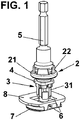
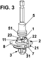
- Figures 1 to 3 are perspective views of the affixing device according to the present invention during its assembly process; in particular, figure 1 shows the moment of the positioning of the device, figure 2 shows the moment of the tightening, and figure 3 shows the moment of the removal of the tool.
- the affixing device comprises the following components: an affixing element 1, a first retaining element 2 and a second retaining element 3.
- the affixing element 1 may be a conventional threaded element, for example, a screw, bolt, or similar element, which preferably comprises a head 11 equipped with a complementary opening with a tool 5, that allows the tightening of said affixing element 1.
- Said tool 5 is shaped such that it allows its insertion into the first retaining element 2 before it is positioned in the openings 6.
- the tool 5 allows its release from the first retaining element 2 with a small external force.
- This affixing element 1 passes through the two openings 6 of the pieces 7, 8 that are to be joined together.
- the pieces may be a structure 7 and a bumper 8, or any other similar pieces.
- the first retaining element 2 in its assembly position ( figures 2 and 3 ) is in contact with said pieces 8, and comprises an accommodation space for the positioning of the tool 5, for example, a screwdriver, to facilitate the tightening of the affixing element 1.
- the first retaining element comprises circular base 21, from which a plurality of perimeter walls 22, which advantageously have a curved footprint, extend in a substantially perpendicular manner.
- each one of said perimeter walls 22 comprises a distal lip 23, which preferably couples in the interior of a slot 51 of the tool 5, as shown in figure 2 .
- the accommodation space of the first retaining element 2 may be defined by only one perimeter wall 21, although in this case, the material of said perimeter wall 21 must be sufficiently elastic to allow the accommodation space and removal of the tool 5. Occasionally, the slot 51 may be placed in the piece 2 and the lip 23 in the tool 5.
- the second retaining element 3 in its assembly position shown in figures 2 and 3 , is in contact with the other piece 7, and according to the embodiment shown, comprises a plurality of feet 31.
- the affixing device according to the present invention also advantageously comprises a seal 4, which in its assembly position is positioned between the first 2 and second 3 retaining elements.
- the affixing device functions as follow: First, with the tool 5 positioned in the accommodation space of the first retaining element 2 and coupled with the affixing element 1 through its head 21, the affixing device is placed in its position of use, passing through the openings 6 of the pieces 7, 8, for example a structure of a vehicle and a bumper ( figure 1 ).
- the tool 5 is held in inside the accommodation space thanks to the presence of the lip 23 on the perimeter walls 22 of the first retaining element 2, which fit into a slot 51 of said tool 5.
- the feet 31 of the second retaining element 3 When the affixing device is positioned in this manner, its alignment with respect to the pieces 7, 8 is guaranteed. To do this, it is also possible for the feet 31 of the second retaining element 3 to form a polygon, whose shape coincides with the shape of the openings 6, so that only the feet 31 will be inserted into said openings 6 if the insertion is carried out in a substantially perpendicular manner.
- the affixing element 1 will be tightened, such that the first and second retaining elements 2, 3 come into contact with both pieces 7, 8, with a sufficient degree of tightness to guarantee correct affixing.
- This tightening is done by turning the affixing element 1 in the proper direction. This turning will cause the displacement of the affixing element inside both retaining elements 2, 3.
- the tool 5 is removed, with this able to be done easily thanks to the elastic nature of the perimeter walls 22 that form the accommodation space of the first retaining element 2.
Landscapes
- Engineering & Computer Science (AREA)
- General Engineering & Computer Science (AREA)
- Mechanical Engineering (AREA)
- Connection Of Plates (AREA)
- Clamps And Clips (AREA)
Description
- The present invention relates to an affixing device for pieces, in particular, for the affixing of vehicle pieces, for example, to secure a bumper to a structure of the vehicle.
- During the manufacture of a vehicle, many pieces must be assembled, using different affixing devices to affix different pieces together. To do this, the two pieces to be affixed normally comprise two openings, into which the affixing device is inserted and then tightened to secure the elements.
- Normally, as discussed in
EP 0 414 162 A1 , the positioning of the affixing device in is position of use is done manually, and a tool, a screwdriver for example, is then inserted to perform the tightening. - Obviously, this essentially manual assembly is prone to errors and imprecision, specifically in regard to the possibility of inserting the affixing device out of alignment in relation to the reference surface.
- In addition, this type of assembly is laborious, because it requires two actions: manual positioning and tightening.
- The aforementioned drawbacks can be especially delicate in the case of the assembly of some pieces, for example, the assembly of a bumper to a structure of a vehicle, because this requires a very robust, fast and secure assembly.
Therefore, one objective of the present invention is to provide an affixing device for pieces that is easily and quickly positioned and that avoids the problems of misalignment. - There is provided an affixing device in accordance with
claim 1. - The affixing device of the invention resolves the aforementioned drawbacks, presenting other advantages that are described below.
- The affixing device for pieces, according to the present invention, comprises an affixing element that can be positioned through an opening in each one of the pieces that are affixed to each other, first and second retaining elements, which, when they are in their affixing position, are in contact with the pieces, that are affixed to each other, with the affixing element passing through said first and second retaining elements, and with the first retaining element comprising an accommodation space for a tool, and is characterized in that said accommodation space of the first retaining element is defined by at least one perimeter wall, the at least one perimeter wall comprises a distal lip for retaining the tool in the accommodation space.
- This allows for faster and simpler assembly of the affixing device, also avoiding problems of misalignment, because the accommodation space of the first retaining element allows the positioning of a tool, for example, a screwdriver, to perform the assembly and then remove the tool.
- According to the invention, said accommodation space of the first retaining element is defined by at least one perimeter wall, or by a plurality of perimeter walls, with each wall preferably having a curved footprint.
- To facilitate the coupling between the first retaining element and a tool, the at least one perimeter wall or each one of the plurality of perimeter walls comprises a distal lip.
- Advantageously, said first retaining element comprises a circular base, which, in its assembly position, is in contact with one of the pieces that are affixed to each other, and preferably, said at least one wall extends substantially perpendicular with respect to said circular base.
- According to a preferred embodiment, said second retaining element comprises a plurality of feet.
- In addition, the affixing device according to the present invention may also comprises a seal positioned between the first and second retaining elements.
- To provide a better understanding of the description, a series of drawings are included that schematically, and solely as an example and not for the purposes of limitation, represent a practical embodiment of the invention.
-
Figures 1 to 3 are perspective views of the affixing device according to the present invention during its assembly process; in particular,figure 1 shows the moment of the positioning of the device,figure 2 shows the moment of the tightening, andfigure 3 shows the moment of the removal of the tool. - As shown in the figures, the affixing device according to the present invention comprises the following components: an
affixing element 1, afirst retaining element 2 and asecond retaining element 3. - The affixing
element 1 may be a conventional threaded element, for example, a screw, bolt, or similar element, which preferably comprises ahead 11 equipped with a complementary opening with atool 5, that allows the tightening of said affixingelement 1. - Said
tool 5 is shaped such that it allows its insertion into thefirst retaining element 2 before it is positioned in theopenings 6. In addition, once thepieces element 1, thetool 5 allows its release from thefirst retaining element 2 with a small external force. - This affixing
element 1 passes through the twoopenings 6 of thepieces structure 7 and abumper 8, or any other similar pieces. - The
first retaining element 2, in its assembly position (figures 2 and3 ) is in contact withsaid pieces 8, and comprises an accommodation space for the positioning of thetool 5, for example, a screwdriver, to facilitate the tightening of the affixingelement 1. - According to the embodiment shown, the first retaining element comprises
circular base 21, from which a plurality ofperimeter walls 22, which advantageously have a curved footprint, extend in a substantially perpendicular manner. - To facilitate the retention of the tool, each one of said
perimeter walls 22 comprises adistal lip 23, which preferably couples in the interior of aslot 51 of thetool 5, as shown infigure 2 . - It should be noted, however, that the accommodation space of the first retaining
element 2 may be defined by only oneperimeter wall 21, although in this case, the material of saidperimeter wall 21 must be sufficiently elastic to allow the accommodation space and removal of thetool 5. Occasionally, theslot 51 may be placed in thepiece 2 and thelip 23 in thetool 5. - The
second retaining element 3, in its assembly position shown infigures 2 and3 , is in contact with theother piece 7, and according to the embodiment shown, comprises a plurality offeet 31. - The affixing device according to the present invention also advantageously comprises a
seal 4, which in its assembly position is positioned between the first 2 and second 3 retaining elements. - The affixing device according to the present invention functions as follow:
First, with thetool 5 positioned in the accommodation space of thefirst retaining element 2 and coupled with the affixingelement 1 through itshead 21, the affixing device is placed in its position of use, passing through theopenings 6 of thepieces figure 1 ). - To facilitate the positioning, the
tool 5 is held in inside the accommodation space thanks to the presence of thelip 23 on theperimeter walls 22 of thefirst retaining element 2, which fit into aslot 51 of saidtool 5. - When the affixing device is positioned in this manner, its alignment with respect to the
pieces feet 31 of the second retainingelement 3 to form a polygon, whose shape coincides with the shape of theopenings 6, so that only thefeet 31 will be inserted into saidopenings 6 if the insertion is carried out in a substantially perpendicular manner. - Once the affixing device has been put into position (
figure 2 ), the affixingelement 1 will be tightened, such that the first andsecond retaining elements pieces - This tightening is done by turning the affixing
element 1 in the proper direction. This turning will cause the displacement of the affixing element inside both retainingelements - Once the tightening has been carried out, the
tool 5 is removed, with this able to be done easily thanks to the elastic nature of theperimeter walls 22 that form the accommodation space of thefirst retaining element 2. - Although reference has been made to a specific embodiment of the invention, it is clear for a person skilled in the art that numerous variations and modifications may be made to the affixing device described, without falling outside the scope of protection defined by the attached claims.
Claims (7)
- An affixing device for pieces, which comprises an affixing element (1) that can be positioned through an opening (6) in each one of the pieces (7, 8)
that are affixed to each other, first and second retaining elements (2, 3), which, when they are in their affixing position, are in contact with the pieces (7, 8) that are affixed to each other, with the affixing element (1) passing through said first and second retaining elements (2, 3), and with the first retaining element (2) comprising an accommodation space for a tool characterized in that said accommodation space of the first retaining element (2) is defined by at least one perimeter wall (22), the at least one perimeter wall (22) comprises a distal lip (23) for retaining the tool in the accommodation space. - The affixing device for pieces according to claim 1, in which said accommodation space of the first retaining element (2) comprises a circular base (21).
- The affixing device for pieces according to claim 2, in which said at least one wall (22) extends substantially perpendicular with respect to the circular base (21).
- The affixing device for pieces according to claim 1, in which said second retaining element (3) comprises a plurality of feet (31).
- The affixing device for pieces according to claim 1, in which the affixing device also comprises a seal (4) positioned between the first and second retaining elements (2, 3).
- The affixing device for pieces according to claim 1, in which the accommodation space of the first retaining element (2) is defined by a plurality of perimeter walls (22), with each wall having a curved footprint.
- The affixing device for pieces according to claim 6 in which each one of the plurality of perimeter walls (22) comprises a distal lip (23).
Applications Claiming Priority (1)
| Application Number | Priority Date | Filing Date | Title |
|---|---|---|---|
| ES201731193A ES2708863B2 (en) | 2017-10-10 | 2017-10-10 | Parts fixing device |
Publications (2)
| Publication Number | Publication Date |
|---|---|
| EP3470688A1 EP3470688A1 (en) | 2019-04-17 |
| EP3470688B1 true EP3470688B1 (en) | 2021-02-24 |
Family
ID=63722316
Family Applications (1)
| Application Number | Title | Priority Date | Filing Date |
|---|---|---|---|
| EP18382670.0A Not-in-force EP3470688B1 (en) | 2017-10-10 | 2018-09-18 | Affixing device for pieces |
Country Status (4)
| Country | Link |
|---|---|
| US (1) | US10927871B2 (en) |
| EP (1) | EP3470688B1 (en) |
| CN (1) | CN109654092B (en) |
| ES (1) | ES2708863B2 (en) |
Families Citing this family (3)
| Publication number | Priority date | Publication date | Assignee | Title |
|---|---|---|---|---|
| DE102020110407B4 (en) * | 2020-04-16 | 2026-04-23 | Illinois Tool Works Inc. | Fastening device for attaching a component to a supporting component |
| DE102021116282A1 (en) * | 2021-06-23 | 2022-12-29 | Böllhoff Verbindungstechnik GmbH | Tolerance compensation element, component with the tolerance compensation element and associated connection between a first and a second component, manufacturing method and connection method |
| USD1056699S1 (en) * | 2022-02-02 | 2025-01-07 | Spartan Mat Llc | Fastening device pin |
Family Cites Families (22)
| Publication number | Priority date | Publication date | Assignee | Title |
|---|---|---|---|---|
| FR2375480A1 (en) * | 1976-12-21 | 1978-07-21 | Comet | IMPROVEMENTS TO FIXING DEVICES |
| US4911593A (en) * | 1989-05-02 | 1990-03-27 | Kephart R Dewain | Ratchet driven threaded fasteners |
| DE3927529C1 (en) * | 1989-08-21 | 1991-03-07 | A. Raymond Kg, 7850 Loerrach, De | |
| US5888012A (en) * | 1996-07-24 | 1999-03-30 | Lockheed Martin Corporation | Large shear tolerant fastening system |
| AU9661298A (en) * | 1997-09-05 | 1999-03-22 | Richard J. Deslauriers | Self-retaining anchor track and method of making and using same |
| US6074146A (en) * | 1999-02-12 | 2000-06-13 | Lucent Technologies, Inc. | Self-aligning connector |
| JP2001289215A (en) * | 2000-04-03 | 2001-10-19 | Aoyama Seisakusho Co Ltd | Waterproof grommet |
| WO2003023260A2 (en) * | 2001-09-07 | 2003-03-20 | Harout Ohanesian | Joint system for water well conduit assemblies |
| US6620167B2 (en) * | 2001-10-17 | 2003-09-16 | Ricahrd J. Deslauriers | Orthopedic screw having driver-locking head |
| JP4446837B2 (en) * | 2004-08-26 | 2010-04-07 | ポップリベット・ファスナー株式会社 | Connecting device |
| DE102005032699B4 (en) * | 2005-07-14 | 2007-08-23 | Itw Automotive Products Gmbh & Co. Kg | fastening device |
| FR2913469B1 (en) * | 2007-03-06 | 2010-12-17 | Raymond A & Cie | DEVICE FOR ASSEMBLING TWO PLATES |
| DE102008012769A1 (en) * | 2008-03-05 | 2009-09-24 | A. Raymond Et Cie | fastener |
| JP5054587B2 (en) * | 2008-03-24 | 2012-10-24 | 株式会社ニフコ | Screw grommet |
| JP5176211B2 (en) * | 2008-12-25 | 2013-04-03 | ポップリベット・ファスナー株式会社 | Spacer clip |
| DE102009030040B4 (en) * | 2009-06-23 | 2019-12-12 | Illinois Tool Works Inc. (N.D.Ges.D. Staates Delaware) | Retaining dowel and method for mounting such a retaining dowel |
| US9452007B1 (en) * | 2011-08-04 | 2016-09-27 | David A. McGuire | Cannulated screw system |
| ES2415956B1 (en) * | 2012-01-24 | 2014-09-02 | IIlinois Tool Works Inc. | PANEL UNION DEVICE AND MANUFACTURING METHOD |
| DE102013004515B4 (en) * | 2013-03-15 | 2023-05-11 | Anvis Deutschland Gmbh | Device for detachably fastening an assembly part |
| CA2809884C (en) * | 2013-03-20 | 2014-02-11 | Guido Stahl | Fastener head and complementary driver |
| DE102014214903A1 (en) * | 2014-07-30 | 2016-02-04 | Bayerische Motoren Werke Aktiengesellschaft | Fixing device for a sandwich component |
| US9869336B2 (en) * | 2015-01-26 | 2018-01-16 | Good Earth Lighting, Inc. | Anchor fastener |
-
2017
- 2017-10-10 ES ES201731193A patent/ES2708863B2/en not_active Expired - Fee Related
-
2018
- 2018-09-18 EP EP18382670.0A patent/EP3470688B1/en not_active Not-in-force
- 2018-09-29 CN CN201811146139.1A patent/CN109654092B/en not_active Expired - Fee Related
- 2018-10-05 US US16/153,169 patent/US10927871B2/en not_active Expired - Fee Related
Non-Patent Citations (1)
| Title |
|---|
| None * |
Also Published As
| Publication number | Publication date |
|---|---|
| US20190107135A1 (en) | 2019-04-11 |
| US10927871B2 (en) | 2021-02-23 |
| CN109654092A (en) | 2019-04-19 |
| CN109654092B (en) | 2022-03-15 |
| ES2708863A1 (en) | 2019-04-11 |
| EP3470688A1 (en) | 2019-04-17 |
| ES2708863B2 (en) | 2020-03-25 |
Similar Documents
| Publication | Publication Date | Title |
|---|---|---|
| EP3470688A1 (en) | Affixing device for pieces | |
| ES2593606T3 (en) | Plug-in connection for the connection of pipes for liquids or gases under pressure | |
| JP6122336B2 (en) | Hole plug | |
| US10516239B2 (en) | Holding frame and method for producing same | |
| ES2387328T3 (en) | Clamping piece for mounting a sensor | |
| US9535403B2 (en) | Device for securing a timepiece dial | |
| US10203001B2 (en) | Suction cup and bracket and method | |
| BR112017016748A2 (en) | ring for attaching a pouch to a pressure distributor and pressurizing a pressure distributor having such a ring | |
| JP2018526187A (en) | Beverage press and method | |
| CN203879878U (en) | Buckle, buckle installation structure and vehicle | |
| CN106274785B (en) | Air bag module | |
| US9663176B1 (en) | Strut fixing device | |
| EP2991178A1 (en) | Clamp for panel-mounted electronics modules or other devices | |
| US10756316B2 (en) | Device for mounting an electrical source | |
| ES2750621T3 (en) | Installation box with fixing device and procedure for mounting an installation box | |
| ES2470115B1 (en) | Fixing element for electrical devices and electrical device equipped with said element | |
| EP3035354B1 (en) | Fastening system with easy removal for electrical and / or electronic devices | |
| JP6213325B2 (en) | Male screw | |
| KR101375109B1 (en) | Nut fixing device | |
| ES2633800T3 (en) | System comprising a clamping frame, a filter element that is fixed therein as well as at least two fixing devices | |
| US10036500B2 (en) | Hose clamp | |
| WO2018162114A8 (en) | Snap connector | |
| ES2587442B1 (en) | Mounting set for recessed electrical and / or electronic devices. | |
| US9718184B2 (en) | Tool box holding accessible but not removable tool when closed | |
| KR101615809B1 (en) | Improved chain cover |
Legal Events
| Date | Code | Title | Description |
|---|---|---|---|
| PUAI | Public reference made under article 153(3) epc to a published international application that has entered the european phase |
Free format text: ORIGINAL CODE: 0009012 |
|
| STAA | Information on the status of an ep patent application or granted ep patent |
Free format text: STATUS: THE APPLICATION HAS BEEN PUBLISHED |
|
| AK | Designated contracting states |
Kind code of ref document: A1 Designated state(s): AL AT BE BG CH CY CZ DE DK EE ES FI FR GB GR HR HU IE IS IT LI LT LU LV MC MK MT NL NO PL PT RO RS SE SI SK SM TR |
|
| AX | Request for extension of the european patent |
Extension state: BA ME |
|
| STAA | Information on the status of an ep patent application or granted ep patent |
Free format text: STATUS: REQUEST FOR EXAMINATION WAS MADE |
|
| 17P | Request for examination filed |
Effective date: 20191017 |
|
| RBV | Designated contracting states (corrected) |
Designated state(s): AL AT BE BG CH CY CZ DE DK EE ES FI FR GB GR HR HU IE IS IT LI LT LU LV MC MK MT NL NO PL PT RO RS SE SI SK SM TR |
|
| RAP1 | Party data changed (applicant data changed or rights of an application transferred) |
Owner name: ILLINOIS TOOL WORKS NC. |
|
| GRAP | Despatch of communication of intention to grant a patent |
Free format text: ORIGINAL CODE: EPIDOSNIGR1 |
|
| STAA | Information on the status of an ep patent application or granted ep patent |
Free format text: STATUS: GRANT OF PATENT IS INTENDED |
|
| INTG | Intention to grant announced |
Effective date: 20200911 |
|
| INTG | Intention to grant announced |
Effective date: 20200918 |
|
| RAP1 | Party data changed (applicant data changed or rights of an application transferred) |
Owner name: ILLINOIS TOOL WORKS INC. |
|
| GRAS | Grant fee paid |
Free format text: ORIGINAL CODE: EPIDOSNIGR3 |
|
| GRAA | (expected) grant |
Free format text: ORIGINAL CODE: 0009210 |
|
| STAA | Information on the status of an ep patent application or granted ep patent |
Free format text: STATUS: THE PATENT HAS BEEN GRANTED |
|
| AK | Designated contracting states |
Kind code of ref document: B1 Designated state(s): AL AT BE BG CH CY CZ DE DK EE ES FI FR GB GR HR HU IE IS IT LI LT LU LV MC MK MT NL NO PL PT RO RS SE SI SK SM TR |
|
| REG | Reference to a national code |
Ref country code: CH Ref legal event code: EP |
|
| REG | Reference to a national code |
Ref country code: AT Ref legal event code: REF Ref document number: 1364790 Country of ref document: AT Kind code of ref document: T Effective date: 20210315 |
|
| REG | Reference to a national code |
Ref country code: IE Ref legal event code: FG4D |
|
| REG | Reference to a national code |
Ref country code: DE Ref legal event code: R096 Ref document number: 602018013001 Country of ref document: DE |
|
| REG | Reference to a national code |
Ref country code: LT Ref legal event code: MG9D |
|
| REG | Reference to a national code |
Ref country code: NL Ref legal event code: MP Effective date: 20210224 |
|
| PG25 | Lapsed in a contracting state [announced via postgrant information from national office to epo] |
Ref country code: PT Free format text: LAPSE BECAUSE OF FAILURE TO SUBMIT A TRANSLATION OF THE DESCRIPTION OR TO PAY THE FEE WITHIN THE PRESCRIBED TIME-LIMIT Effective date: 20210624 Ref country code: NO Free format text: LAPSE BECAUSE OF FAILURE TO SUBMIT A TRANSLATION OF THE DESCRIPTION OR TO PAY THE FEE WITHIN THE PRESCRIBED TIME-LIMIT Effective date: 20210524 Ref country code: LT Free format text: LAPSE BECAUSE OF FAILURE TO SUBMIT A TRANSLATION OF THE DESCRIPTION OR TO PAY THE FEE WITHIN THE PRESCRIBED TIME-LIMIT Effective date: 20210224 Ref country code: HR Free format text: LAPSE BECAUSE OF FAILURE TO SUBMIT A TRANSLATION OF THE DESCRIPTION OR TO PAY THE FEE WITHIN THE PRESCRIBED TIME-LIMIT Effective date: 20210224 Ref country code: GR Free format text: LAPSE BECAUSE OF FAILURE TO SUBMIT A TRANSLATION OF THE DESCRIPTION OR TO PAY THE FEE WITHIN THE PRESCRIBED TIME-LIMIT Effective date: 20210525 Ref country code: FI Free format text: LAPSE BECAUSE OF FAILURE TO SUBMIT A TRANSLATION OF THE DESCRIPTION OR TO PAY THE FEE WITHIN THE PRESCRIBED TIME-LIMIT Effective date: 20210224 Ref country code: BG Free format text: LAPSE BECAUSE OF FAILURE TO SUBMIT A TRANSLATION OF THE DESCRIPTION OR TO PAY THE FEE WITHIN THE PRESCRIBED TIME-LIMIT Effective date: 20210524 |
|
| REG | Reference to a national code |
Ref country code: AT Ref legal event code: MK05 Ref document number: 1364790 Country of ref document: AT Kind code of ref document: T Effective date: 20210224 |
|
| PG25 | Lapsed in a contracting state [announced via postgrant information from national office to epo] |
Ref country code: PL Free format text: LAPSE BECAUSE OF FAILURE TO SUBMIT A TRANSLATION OF THE DESCRIPTION OR TO PAY THE FEE WITHIN THE PRESCRIBED TIME-LIMIT Effective date: 20210224 Ref country code: RS Free format text: LAPSE BECAUSE OF FAILURE TO SUBMIT A TRANSLATION OF THE DESCRIPTION OR TO PAY THE FEE WITHIN THE PRESCRIBED TIME-LIMIT Effective date: 20210224 Ref country code: LV Free format text: LAPSE BECAUSE OF FAILURE TO SUBMIT A TRANSLATION OF THE DESCRIPTION OR TO PAY THE FEE WITHIN THE PRESCRIBED TIME-LIMIT Effective date: 20210224 Ref country code: NL Free format text: LAPSE BECAUSE OF FAILURE TO SUBMIT A TRANSLATION OF THE DESCRIPTION OR TO PAY THE FEE WITHIN THE PRESCRIBED TIME-LIMIT Effective date: 20210224 Ref country code: SE Free format text: LAPSE BECAUSE OF FAILURE TO SUBMIT A TRANSLATION OF THE DESCRIPTION OR TO PAY THE FEE WITHIN THE PRESCRIBED TIME-LIMIT Effective date: 20210224 |
|
| PG25 | Lapsed in a contracting state [announced via postgrant information from national office to epo] |
Ref country code: IS Free format text: LAPSE BECAUSE OF FAILURE TO SUBMIT A TRANSLATION OF THE DESCRIPTION OR TO PAY THE FEE WITHIN THE PRESCRIBED TIME-LIMIT Effective date: 20210624 |
|
| PG25 | Lapsed in a contracting state [announced via postgrant information from national office to epo] |
Ref country code: SM Free format text: LAPSE BECAUSE OF FAILURE TO SUBMIT A TRANSLATION OF THE DESCRIPTION OR TO PAY THE FEE WITHIN THE PRESCRIBED TIME-LIMIT Effective date: 20210224 Ref country code: AT Free format text: LAPSE BECAUSE OF FAILURE TO SUBMIT A TRANSLATION OF THE DESCRIPTION OR TO PAY THE FEE WITHIN THE PRESCRIBED TIME-LIMIT Effective date: 20210224 Ref country code: EE Free format text: LAPSE BECAUSE OF FAILURE TO SUBMIT A TRANSLATION OF THE DESCRIPTION OR TO PAY THE FEE WITHIN THE PRESCRIBED TIME-LIMIT Effective date: 20210224 Ref country code: CZ Free format text: LAPSE BECAUSE OF FAILURE TO SUBMIT A TRANSLATION OF THE DESCRIPTION OR TO PAY THE FEE WITHIN THE PRESCRIBED TIME-LIMIT Effective date: 20210224 |
|
| REG | Reference to a national code |
Ref country code: DE Ref legal event code: R097 Ref document number: 602018013001 Country of ref document: DE |
|
| PG25 | Lapsed in a contracting state [announced via postgrant information from national office to epo] |
Ref country code: DK Free format text: LAPSE BECAUSE OF FAILURE TO SUBMIT A TRANSLATION OF THE DESCRIPTION OR TO PAY THE FEE WITHIN THE PRESCRIBED TIME-LIMIT Effective date: 20210224 Ref country code: SK Free format text: LAPSE BECAUSE OF FAILURE TO SUBMIT A TRANSLATION OF THE DESCRIPTION OR TO PAY THE FEE WITHIN THE PRESCRIBED TIME-LIMIT Effective date: 20210224 Ref country code: RO Free format text: LAPSE BECAUSE OF FAILURE TO SUBMIT A TRANSLATION OF THE DESCRIPTION OR TO PAY THE FEE WITHIN THE PRESCRIBED TIME-LIMIT Effective date: 20210224 |
|
| PLBE | No opposition filed within time limit |
Free format text: ORIGINAL CODE: 0009261 |
|
| STAA | Information on the status of an ep patent application or granted ep patent |
Free format text: STATUS: NO OPPOSITION FILED WITHIN TIME LIMIT |
|
| PG25 | Lapsed in a contracting state [announced via postgrant information from national office to epo] |
Ref country code: ES Free format text: LAPSE BECAUSE OF FAILURE TO SUBMIT A TRANSLATION OF THE DESCRIPTION OR TO PAY THE FEE WITHIN THE PRESCRIBED TIME-LIMIT Effective date: 20210224 Ref country code: AL Free format text: LAPSE BECAUSE OF FAILURE TO SUBMIT A TRANSLATION OF THE DESCRIPTION OR TO PAY THE FEE WITHIN THE PRESCRIBED TIME-LIMIT Effective date: 20210224 |
|
| 26N | No opposition filed |
Effective date: 20211125 |
|
| PG25 | Lapsed in a contracting state [announced via postgrant information from national office to epo] |
Ref country code: SI Free format text: LAPSE BECAUSE OF FAILURE TO SUBMIT A TRANSLATION OF THE DESCRIPTION OR TO PAY THE FEE WITHIN THE PRESCRIBED TIME-LIMIT Effective date: 20210224 |
|
| PG25 | Lapsed in a contracting state [announced via postgrant information from national office to epo] |
Ref country code: IT Free format text: LAPSE BECAUSE OF FAILURE TO SUBMIT A TRANSLATION OF THE DESCRIPTION OR TO PAY THE FEE WITHIN THE PRESCRIBED TIME-LIMIT Effective date: 20210224 |
|
| REG | Reference to a national code |
Ref country code: CH Ref legal event code: PL |
|
| REG | Reference to a national code |
Ref country code: BE Ref legal event code: MM Effective date: 20210930 |
|
| PG25 | Lapsed in a contracting state [announced via postgrant information from national office to epo] |
Ref country code: IS Free format text: LAPSE BECAUSE OF FAILURE TO SUBMIT A TRANSLATION OF THE DESCRIPTION OR TO PAY THE FEE WITHIN THE PRESCRIBED TIME-LIMIT Effective date: 20210624 Ref country code: MC Free format text: LAPSE BECAUSE OF FAILURE TO SUBMIT A TRANSLATION OF THE DESCRIPTION OR TO PAY THE FEE WITHIN THE PRESCRIBED TIME-LIMIT Effective date: 20210224 |
|
| PG25 | Lapsed in a contracting state [announced via postgrant information from national office to epo] |
Ref country code: LU Free format text: LAPSE BECAUSE OF NON-PAYMENT OF DUE FEES Effective date: 20210918 Ref country code: IE Free format text: LAPSE BECAUSE OF NON-PAYMENT OF DUE FEES Effective date: 20210918 Ref country code: FR Free format text: LAPSE BECAUSE OF NON-PAYMENT OF DUE FEES Effective date: 20210930 Ref country code: BE Free format text: LAPSE BECAUSE OF NON-PAYMENT OF DUE FEES Effective date: 20210930 |
|
| PG25 | Lapsed in a contracting state [announced via postgrant information from national office to epo] |
Ref country code: LI Free format text: LAPSE BECAUSE OF NON-PAYMENT OF DUE FEES Effective date: 20210930 Ref country code: CH Free format text: LAPSE BECAUSE OF NON-PAYMENT OF DUE FEES Effective date: 20210930 |
|
| GBPC | Gb: european patent ceased through non-payment of renewal fee |
Effective date: 20220918 |
|
| PG25 | Lapsed in a contracting state [announced via postgrant information from national office to epo] |
Ref country code: CY Free format text: LAPSE BECAUSE OF FAILURE TO SUBMIT A TRANSLATION OF THE DESCRIPTION OR TO PAY THE FEE WITHIN THE PRESCRIBED TIME-LIMIT Effective date: 20210224 |
|
| P01 | Opt-out of the competence of the unified patent court (upc) registered |
Effective date: 20230606 |
|
| PG25 | Lapsed in a contracting state [announced via postgrant information from national office to epo] |
Ref country code: HU Free format text: LAPSE BECAUSE OF FAILURE TO SUBMIT A TRANSLATION OF THE DESCRIPTION OR TO PAY THE FEE WITHIN THE PRESCRIBED TIME-LIMIT; INVALID AB INITIO Effective date: 20180918 |
|
| PG25 | Lapsed in a contracting state [announced via postgrant information from national office to epo] |
Ref country code: GB Free format text: LAPSE BECAUSE OF NON-PAYMENT OF DUE FEES Effective date: 20220918 |
|
| PGFP | Annual fee paid to national office [announced via postgrant information from national office to epo] |
Ref country code: DE Payment date: 20230927 Year of fee payment: 6 |
|
| PG25 | Lapsed in a contracting state [announced via postgrant information from national office to epo] |
Ref country code: MK Free format text: LAPSE BECAUSE OF FAILURE TO SUBMIT A TRANSLATION OF THE DESCRIPTION OR TO PAY THE FEE WITHIN THE PRESCRIBED TIME-LIMIT Effective date: 20210224 |
|
| PG25 | Lapsed in a contracting state [announced via postgrant information from national office to epo] |
Ref country code: MT Free format text: LAPSE BECAUSE OF FAILURE TO SUBMIT A TRANSLATION OF THE DESCRIPTION OR TO PAY THE FEE WITHIN THE PRESCRIBED TIME-LIMIT Effective date: 20210224 |
|
| REG | Reference to a national code |
Ref country code: DE Ref legal event code: R119 Ref document number: 602018013001 Country of ref document: DE |
|
| PG25 | Lapsed in a contracting state [announced via postgrant information from national office to epo] |
Ref country code: DE Free format text: LAPSE BECAUSE OF NON-PAYMENT OF DUE FEES Effective date: 20250401 |
|
| PG25 | Lapsed in a contracting state [announced via postgrant information from national office to epo] |
Ref country code: TR Free format text: LAPSE BECAUSE OF FAILURE TO SUBMIT A TRANSLATION OF THE DESCRIPTION OR TO PAY THE FEE WITHIN THE PRESCRIBED TIME-LIMIT Effective date: 20210224 |