EP3470671A1 - Wind turbine pitch bearing with line contact rolling elements - Google Patents
Wind turbine pitch bearing with line contact rolling elements Download PDFInfo
- Publication number
- EP3470671A1 EP3470671A1 EP18198194.5A EP18198194A EP3470671A1 EP 3470671 A1 EP3470671 A1 EP 3470671A1 EP 18198194 A EP18198194 A EP 18198194A EP 3470671 A1 EP3470671 A1 EP 3470671A1
- Authority
- EP
- European Patent Office
- Prior art keywords
- rolling elements
- bearing
- line contact
- pitch bearing
- pitch
- Prior art date
- Legal status (The legal status is an assumption and is not a legal conclusion. Google has not performed a legal analysis and makes no representation as to the accuracy of the status listed.)
- Granted
Links
Images






Classifications
-
- F—MECHANICAL ENGINEERING; LIGHTING; HEATING; WEAPONS; BLASTING
- F03—MACHINES OR ENGINES FOR LIQUIDS; WIND, SPRING, OR WEIGHT MOTORS; PRODUCING MECHANICAL POWER OR A REACTIVE PROPULSIVE THRUST, NOT OTHERWISE PROVIDED FOR
- F03D—WIND MOTORS
- F03D80/00—Details, components or accessories not provided for in groups F03D1/00 - F03D17/00
- F03D80/70—Bearing or lubricating arrangements
-
- F—MECHANICAL ENGINEERING; LIGHTING; HEATING; WEAPONS; BLASTING
- F16—ENGINEERING ELEMENTS AND UNITS; GENERAL MEASURES FOR PRODUCING AND MAINTAINING EFFECTIVE FUNCTIONING OF MACHINES OR INSTALLATIONS; THERMAL INSULATION IN GENERAL
- F16C—SHAFTS; FLEXIBLE SHAFTS; ELEMENTS OR CRANKSHAFT MECHANISMS; ROTARY BODIES OTHER THAN GEARING ELEMENTS; BEARINGS
- F16C33/00—Parts of bearings; Special methods for making bearings or parts thereof
- F16C33/30—Parts of ball or roller bearings
- F16C33/58—Raceways; Race rings
- F16C33/583—Details of specific parts of races
- F16C33/585—Details of specific parts of races of raceways, e.g. ribs to guide the rollers
-
- F—MECHANICAL ENGINEERING; LIGHTING; HEATING; WEAPONS; BLASTING
- F03—MACHINES OR ENGINES FOR LIQUIDS; WIND, SPRING, OR WEIGHT MOTORS; PRODUCING MECHANICAL POWER OR A REACTIVE PROPULSIVE THRUST, NOT OTHERWISE PROVIDED FOR
- F03D—WIND MOTORS
- F03D7/00—Controlling wind motors
- F03D7/02—Controlling wind motors the wind motors having rotation axis substantially parallel to the air flow entering the rotor
- F03D7/022—Adjusting aerodynamic properties of the blades
- F03D7/0224—Adjusting blade pitch
-
- F—MECHANICAL ENGINEERING; LIGHTING; HEATING; WEAPONS; BLASTING
- F16—ENGINEERING ELEMENTS AND UNITS; GENERAL MEASURES FOR PRODUCING AND MAINTAINING EFFECTIVE FUNCTIONING OF MACHINES OR INSTALLATIONS; THERMAL INSULATION IN GENERAL
- F16C—SHAFTS; FLEXIBLE SHAFTS; ELEMENTS OR CRANKSHAFT MECHANISMS; ROTARY BODIES OTHER THAN GEARING ELEMENTS; BEARINGS
- F16C19/00—Bearings with rolling contact, for exclusively rotary movement
- F16C19/22—Bearings with rolling contact, for exclusively rotary movement with bearing rollers essentially of the same size in one or more circular rows, e.g. needle bearings
- F16C19/34—Bearings with rolling contact, for exclusively rotary movement with bearing rollers essentially of the same size in one or more circular rows, e.g. needle bearings for both radial and axial load
- F16C19/36—Bearings with rolling contact, for exclusively rotary movement with bearing rollers essentially of the same size in one or more circular rows, e.g. needle bearings for both radial and axial load with a single row of rollers
- F16C19/364—Bearings with rolling contact, for exclusively rotary movement with bearing rollers essentially of the same size in one or more circular rows, e.g. needle bearings for both radial and axial load with a single row of rollers with tapered rollers, i.e. rollers having essentially the shape of a truncated cone
-
- F—MECHANICAL ENGINEERING; LIGHTING; HEATING; WEAPONS; BLASTING
- F16—ENGINEERING ELEMENTS AND UNITS; GENERAL MEASURES FOR PRODUCING AND MAINTAINING EFFECTIVE FUNCTIONING OF MACHINES OR INSTALLATIONS; THERMAL INSULATION IN GENERAL
- F16C—SHAFTS; FLEXIBLE SHAFTS; ELEMENTS OR CRANKSHAFT MECHANISMS; ROTARY BODIES OTHER THAN GEARING ELEMENTS; BEARINGS
- F16C19/00—Bearings with rolling contact, for exclusively rotary movement
- F16C19/22—Bearings with rolling contact, for exclusively rotary movement with bearing rollers essentially of the same size in one or more circular rows, e.g. needle bearings
- F16C19/34—Bearings with rolling contact, for exclusively rotary movement with bearing rollers essentially of the same size in one or more circular rows, e.g. needle bearings for both radial and axial load
- F16C19/38—Bearings with rolling contact, for exclusively rotary movement with bearing rollers essentially of the same size in one or more circular rows, e.g. needle bearings for both radial and axial load with two or more rows of rollers
- F16C19/383—Bearings with rolling contact, for exclusively rotary movement with bearing rollers essentially of the same size in one or more circular rows, e.g. needle bearings for both radial and axial load with two or more rows of rollers with tapered rollers, i.e. rollers having essentially the shape of a truncated cone
-
- F—MECHANICAL ENGINEERING; LIGHTING; HEATING; WEAPONS; BLASTING
- F16—ENGINEERING ELEMENTS AND UNITS; GENERAL MEASURES FOR PRODUCING AND MAINTAINING EFFECTIVE FUNCTIONING OF MACHINES OR INSTALLATIONS; THERMAL INSULATION IN GENERAL
- F16C—SHAFTS; FLEXIBLE SHAFTS; ELEMENTS OR CRANKSHAFT MECHANISMS; ROTARY BODIES OTHER THAN GEARING ELEMENTS; BEARINGS
- F16C33/00—Parts of bearings; Special methods for making bearings or parts thereof
- F16C33/30—Parts of ball or roller bearings
- F16C33/34—Rollers; Needles
- F16C33/36—Rollers; Needles with bearing-surfaces other than cylindrical, e.g. tapered; with grooves in the bearing surfaces
- F16C33/366—Tapered rollers, i.e. rollers generally shaped as truncated cones
-
- F—MECHANICAL ENGINEERING; LIGHTING; HEATING; WEAPONS; BLASTING
- F16—ENGINEERING ELEMENTS AND UNITS; GENERAL MEASURES FOR PRODUCING AND MAINTAINING EFFECTIVE FUNCTIONING OF MACHINES OR INSTALLATIONS; THERMAL INSULATION IN GENERAL
- F16C—SHAFTS; FLEXIBLE SHAFTS; ELEMENTS OR CRANKSHAFT MECHANISMS; ROTARY BODIES OTHER THAN GEARING ELEMENTS; BEARINGS
- F16C33/00—Parts of bearings; Special methods for making bearings or parts thereof
- F16C33/30—Parts of ball or roller bearings
- F16C33/58—Raceways; Race rings
- F16C33/581—Raceways; Race rings integral with other parts, e.g. with housings or machine elements such as shafts or gear wheels
-
- F—MECHANICAL ENGINEERING; LIGHTING; HEATING; WEAPONS; BLASTING
- F05—INDEXING SCHEMES RELATING TO ENGINES OR PUMPS IN VARIOUS SUBCLASSES OF CLASSES F01-F04
- F05B—INDEXING SCHEME RELATING TO WIND, SPRING, WEIGHT, INERTIA OR LIKE MOTORS, TO MACHINES OR ENGINES FOR LIQUIDS COVERED BY SUBCLASSES F03B, F03D AND F03G
- F05B2240/00—Components
- F05B2240/50—Bearings
- F05B2240/52—Axial thrust bearings
-
- F—MECHANICAL ENGINEERING; LIGHTING; HEATING; WEAPONS; BLASTING
- F05—INDEXING SCHEMES RELATING TO ENGINES OR PUMPS IN VARIOUS SUBCLASSES OF CLASSES F01-F04
- F05B—INDEXING SCHEME RELATING TO WIND, SPRING, WEIGHT, INERTIA OR LIKE MOTORS, TO MACHINES OR ENGINES FOR LIQUIDS COVERED BY SUBCLASSES F03B, F03D AND F03G
- F05B2260/00—Function
- F05B2260/70—Adjusting of angle of incidence or attack of rotating blades
- F05B2260/79—Bearing, support or actuation arrangements therefor
-
- F—MECHANICAL ENGINEERING; LIGHTING; HEATING; WEAPONS; BLASTING
- F16—ENGINEERING ELEMENTS AND UNITS; GENERAL MEASURES FOR PRODUCING AND MAINTAINING EFFECTIVE FUNCTIONING OF MACHINES OR INSTALLATIONS; THERMAL INSULATION IN GENERAL
- F16C—SHAFTS; FLEXIBLE SHAFTS; ELEMENTS OR CRANKSHAFT MECHANISMS; ROTARY BODIES OTHER THAN GEARING ELEMENTS; BEARINGS
- F16C2300/00—Application independent of particular apparatuses
- F16C2300/10—Application independent of particular apparatuses related to size
- F16C2300/14—Large applications, e.g. bearings having an inner diameter exceeding 500 mm
-
- F—MECHANICAL ENGINEERING; LIGHTING; HEATING; WEAPONS; BLASTING
- F16—ENGINEERING ELEMENTS AND UNITS; GENERAL MEASURES FOR PRODUCING AND MAINTAINING EFFECTIVE FUNCTIONING OF MACHINES OR INSTALLATIONS; THERMAL INSULATION IN GENERAL
- F16C—SHAFTS; FLEXIBLE SHAFTS; ELEMENTS OR CRANKSHAFT MECHANISMS; ROTARY BODIES OTHER THAN GEARING ELEMENTS; BEARINGS
- F16C2360/00—Engines or pumps
- F16C2360/31—Wind motors
-
- Y—GENERAL TAGGING OF NEW TECHNOLOGICAL DEVELOPMENTS; GENERAL TAGGING OF CROSS-SECTIONAL TECHNOLOGIES SPANNING OVER SEVERAL SECTIONS OF THE IPC; TECHNICAL SUBJECTS COVERED BY FORMER USPC CROSS-REFERENCE ART COLLECTIONS [XRACs] AND DIGESTS
- Y02—TECHNOLOGIES OR APPLICATIONS FOR MITIGATION OR ADAPTATION AGAINST CLIMATE CHANGE
- Y02E—REDUCTION OF GREENHOUSE GAS [GHG] EMISSIONS, RELATED TO ENERGY GENERATION, TRANSMISSION OR DISTRIBUTION
- Y02E10/00—Energy generation through renewable energy sources
- Y02E10/70—Wind energy
- Y02E10/72—Wind turbines with rotation axis in wind direction
-
- Y—GENERAL TAGGING OF NEW TECHNOLOGICAL DEVELOPMENTS; GENERAL TAGGING OF CROSS-SECTIONAL TECHNOLOGIES SPANNING OVER SEVERAL SECTIONS OF THE IPC; TECHNICAL SUBJECTS COVERED BY FORMER USPC CROSS-REFERENCE ART COLLECTIONS [XRACs] AND DIGESTS
- Y02—TECHNOLOGIES OR APPLICATIONS FOR MITIGATION OR ADAPTATION AGAINST CLIMATE CHANGE
- Y02E—REDUCTION OF GREENHOUSE GAS [GHG] EMISSIONS, RELATED TO ENERGY GENERATION, TRANSMISSION OR DISTRIBUTION
- Y02E10/00—Energy generation through renewable energy sources
- Y02E10/70—Wind energy
- Y02E10/74—Wind turbines with rotation axis perpendicular to the wind direction
Definitions
- the present subject matter relates generally to wind turbines and, more particularly, to a pitch bearing for a wind turbine utilizing line contact rolling elements.
- Wind power is considered one of the cleanest, most environmentally friendly energy sources presently available, and wind turbines have gained increased attention in this regard.
- a modern wind turbine typically includes a tower, generator, gearbox, nacelle, and one or more rotor blades.
- the rotor blades capture kinetic energy from wind using known airfoil principles and transmit the kinetic energy through rotational energy to turn a shaft coupling the rotor blades to a gearbox, or if a gearbox is not used, directly to the generator.
- the generator then converts the mechanical energy to electrical energy that may be deployed to a utility grid.
- the wind turbine may include various bearings to facilitate rotation of its various components.
- bearings include pitch bearings and yaw bearings. More specifically, yaw bearings are configured to rotate the nacelle with respect to the tower as a function of the incoming wind.
- pitch bearings are arranged between a blade root of the rotor blades and the hub. Therefore, the pitch bearings rotate or pitch the rotor blades with respect to the incoming wind.
- Such bearings generally include an outer race, an inner race rotatable relative to the outer race, and a plurality of rolling elements therebetween.
- Many wind turbine bearings include point contact rolling elements, e.g. ball bearings 1, such as those illustrated in FIG. 1 .
- some wind turbine bearings may include line contact rolling elements, such as cylindrical rolling elements 2, having a 0° and 90° contact angle configuration.
- Conventional line contact rolling elements typically include the rolling elements arranged in a 0° and 90° contact angle configuration. More specifically, as shown in FIG. 3 , a partial, cross-sectional view of a line contact rolling element bearing 3 according to conventional construction is illustrated. As shown, the line contact rolling element bearing 3 includes an outer race 7 and an inner race 8 rotatable relative to the outer race 7 via a plurality of line contact rolling elements 4, 5, 6. More specifically, as shown, the upper and lower line contact rolling elements 4, 5 have a 90° contact angle, whereas the middle line contact rolling element 6 has a 0° contact angle.
- the rolling elements having a 90° contact angle experience relative sliding therebetween as well as with raceway in order to function.
- Successful utilization of line contact rolling elements in a 90° contact angle configuration typically relies on operation in lubrication lambda regimes greater than one such that the relative sliding is not detrimental to bearing performance.
- wind turbine pitch bearings experience lambda ratios approaching zero.
- line contact rolling element bearings are used as pitch bearings, such sliding can scuff and wear interface surfaces, generating heat and debris inside the bearing.
- a pitch bearing having line contact rolling elements that addresses the aforementioned issues would be welcomed in the technology.
- a pitch bearing with less than three rows of line contact rolling elements would be beneficial.
- the present disclosure is directed to a pitch bearing for coupling a rotor blade to a hub of a wind turbine.
- the pitch bearing includes an outer race configured to be coupled to the hub, an inner race rotatable relative to the outer race and configured to be coupled to the rotor blade, and a first plurality of line contact rolling elements.
- the outer race defines a first outer raceway wall and the inner race defines a first inner raceway wall.
- the first plurality of line contact rolling elements is disposed between the first inner and outer raceway walls. Each of the plurality of line contact rolling elements defines a predetermined contact angle.
- the predetermined contact angle is defined as an angle between a reference line extending perpendicular to a longitudinal axis of one of the plurality of line contact rolling elements and a reference line extending parallel to a horizontal plane of the pitch bearing. Further, the predetermined contact angle includes angles between 0 degrees (°) and 90°.
- the outer race may further define a second outer raceway wall and the inner race may define a second inner raceway wall.
- the pitch bearing may include a second plurality of line contact rolling elements disposed between the second inner and outer raceway walls.
- first and second plurality of line contact rolling elements may include cylindrical rolling elements.
- the first and second plurality of line contact rolling elements may include tapered rolling elements.
- reference lines extending parallel to the longitudinal axes of the first and second plurality of tapered rolling elements may converge at a common point of the pitch bearing and define a taper angle.
- the inner and outer races may be segments of cones with the rolling elements being tapered so that the conical surfaces of the races and the rolling element axes, if projected, would meet at the same common point on the main axis of the bearing.
- the convergence of the surfaces of the races and rolling elements defines the taper angle.
- the taper angle may include angles ranging from about 0.25° to about 6°.
- the pitch bearing may further include at least one additional plurality of rolling elements.
- the pitch bearing may also include a raceway rib extending between the first and second plurality of rolling elements.
- the present disclosure is directed to a pitch bearing for coupling a rotor blade to a hub of a wind turbine.
- the pitch bearing includes an outer race configured to be coupled to the hub, an inner race rotatable relative to the outer race and configured to be coupled to the rotor blade, and a first plurality of line contact rolling elements.
- the outer race defines a first outer raceway wall and the inner race defines a first inner raceway wall.
- the first plurality of line contact rolling elements is disposed between the first inner and outer raceway walls. Each of the plurality of line contact rolling elements defines a predetermined contact angle.
- the predetermined contact angle is defined as an angle between a reference line extending perpendicular to a longitudinal axis of one of the plurality of line contact rolling elements and a reference line extending parallel to a horizontal plane of the pitch bearing. Further, the predetermined contact angle includes non-0° angles and non-90° angles. It should be understood that the pitch bearing may further include any of the additional features described herein.
- the present disclosure is directed to a slewing ring bearing.
- the slewing ring includes an outer race, an inner race rotatable relative to the outer race, and a plurality of line contact rolling elements.
- the inner race is positioned relative to the outer race such that at least one raceway is defined between the inner and outer races.
- the plurality of line contact rolling elements extends circumferentially around the raceway.
- Each of the plurality of line contact rolling elements defines a predetermined contact angle.
- the predetermined contact angle is defined as an angle between a reference line extending perpendicular to a longitudinal axis of one of the plurality of line contact rolling elements and a reference line extending parallel to a horizontal plane of the pitch bearing. Further, the predetermined contact angle includes non-0° angles and non-90° angles. It should be understood that the slewing ring bearing may further include any of the additional features described herein.
- a pitch bearing of the wind turbine may include first and second rows of line contact rolling elements arranged between inner and outer races of the bearing.
- the disclosed pitch bearings have been uniquely configured to handle the dynamic loading of a wind turbine. Specifically, due to erratic moment loading and the fact that each pitch bearing is mounted directly to a relatively flexible rotor blade, pitch bearings must be equipped to handle axial and radial loads that can vary significantly with time. As will be described below, the disclosed bearings provide for non-0° and non-90° contact angles, thereby reducing the resultant loads applied through each rolling element and eliminating sliding therebetween. Accordingly, each rolling element may deflect less and, thus, may retain more of an overall share of the entire load, thereby decreasing the stress on the bearing.
- the disclosed bearing configurations may be utilized within any suitable wind turbine bearing.
- yaw bearings are often subject to dynamic loading during operation of a wind turbine.
- the disclosed bearing configurations may also be implemented within the yaw bearing of a wind turbine to reduce stresses within the bearing.
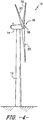
- FIG. 4 illustrates a perspective view of one embodiment of a wind turbine 10 according to the present disclosure.
- the wind turbine 10 generally includes a tower 12, a nacelle 14 mounted on the tower 12, and a rotor 16 coupled to the nacelle 14.
- the rotor 16 includes a rotatable hub 18 and at least one rotor blade 20 coupled to and extending outwardly from the hub 18.
- the rotor 16 includes three rotor blades 20.
- the rotor 16 may include more or less than three rotor blades 20.
- Each rotor blade 20 may be spaced about the hub 18 to facilitate rotating the rotor 16 to enable kinetic energy to be transferred from the wind into usable mechanical energy, and subsequently, electrical energy.
- the hub 18 maybe rotatably coupled to an electric generator 25 ( FIG. 5 ) positioned within the nacelle 14 to permit electrical energy to be produced.
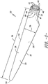
- the rotor blade 20 includes a blade root 22 configured for mounting the rotor blade 20 to the hub 18 of the wind turbine 10 ( FIG. 4 ) and a blade tip 24 disposed opposite the blade root 22.
- a body 26 of the rotor blade 20 may extend lengthwise between the blade root 22 and the blade tip 24 and may generally serve as the outer shell of the rotor blade 20.
- the body 26 may define an aerodynamic profile (e.g., by defining an airfoil shaped cross-section, such as a symmetrical or cambered airfoil-shaped cross-section) to enable the rotor blade 20 to capture kinetic energy from the wind using known aerodynamic principles.
- the body 26 may generally include a pressure side 28 and a suction side 30 extending between a leading edge 32 and a trailing edge 34.
- the rotor blade 20 may have a span 36 defining the total length of the body 26 between the blade root 22 and the blade tip 24 and a chord 38 defining the total length of the body 26 between the leading edge 32 and the trailing edge 34.
- the chord 38 may vary in length with respect to the span 26 as the body 26 extends from the blade root 22 to the blade tip 24.
- each root attachment assembly 40 may include a barrel nut 42 mounted within a portion of the blade root 22 and a root bolt 44 coupled to and extending from the barrel nut 42 so as to project outwardly from a root end 46 of the blade root 22.
- the root bolts 44 may generally be used to couple the blade root 22 to the hub 18 (e.g., via one of the pitch bearings 50), as will be described in greater detail below.
- the generator 25 may be disposed within the nacelle 14.
- the generator 25 may be coupled to the rotor 16 of the wind turbine 10 for generating electrical power from the rotational energy generated by the rotor 16.
- the rotor 16 may include a rotor shaft 27 coupled to the hub 18 for rotation therewith.
- the generator 25 may then be coupled to the rotor shaft 27 such that rotation of the rotor shaft 27 drives the generator 25.
- the generator 25 includes a generator shaft 29 rotatably coupled to the rotor shaft 27 through a gearbox 31.
- the generator shaft 29 may be rotatably coupled directly to the rotor shaft 27.
- the generator 25 may be directly rotatably coupled to the rotor shaft 27 (often referred to as a "direct-drive wind turbine").
- the wind turbine 10 may include numerous slewing ring bearings for allowing rotation of various components of the wind turbine 10.
- the term "slewing ring bearing” may be used to refer to the yaw bearing 35 of the wind turbine 10 and/or one of the pitch bearings 50 of the wind turbine 10.
- the slewing ring bearings 35, 50 may generally have any suitable configuration, including one or more of the bearing configurations described below.
- the slewing ring bearings 35, 50 may include an inner race and an outer race rotatable relative to the inner race, with one or more rows of rolling elements being disposed between the inner and outer races.
- the wind turbine 10 may include one or more yaw drive mechanisms 33 mounted to and/or through a bedplate 15 positioned atop the wind turbine tower 12.
- each yaw drive mechanism 33 may be mounted to and/or through the bedplate 15 so as to engage the yaw bearing 35 coupled between the bedplate 15 and the tower 12 of the wind turbine 10.
- the yaw bearing 35 may be mounted to the bed plate 15 such that, as the yaw bearing 35 rotates about a yaw axis (not shown) of the wind turbine 10, the bedplate 15 and, thus, the nacelle 14 are similarly rotated about the yaw axis.
- the illustrated wind turbine 10 is shown as including two yaw drive mechanisms 232, the wind turbine 10 may generally include any suitable number of yaw drive mechanisms 232.
- the wind turbine 10 may also include a plurality of pitch bearings 50 (one of which is shown), with each pitch bearing 50 being coupled between the hub 18 and one of the rotor blades 20.
- the pitch bearings 50 may be configured to allow each rotor blade 20 to be rotated about its pitch axis 39 (e.g., via a pitch adjustment mechanism 45), thereby allowing the orientation of each blade 20 to be adjusted relative to the direction of the wind.
- the pitch and yaw drive mechanisms 33, 45 may have any suitable configuration and may include any suitable components known in the art that allow such mechanisms 33, 45 to function as described herein.
- the pitch adjustment mechanism 45 may include a pitch drive motor 37 (e.g., an electric motor), a pitch drive gearbox 41, and a pitch drive pinion 43.
- the pitch drive motor 37 may be coupled to the pitch drive gearbox 41 so that the motor 37 imparts mechanical force to the gearbox 41.
- the gearbox 41 may be coupled to the pitch drive pinion 43 for rotation therewith.
- the pinion 43 may, in turn, be in rotational engagement with the inner race 54.
- the pitch bearing 50 includes an outer bearing race 52, an inner bearing race 54, and a plurality of line contact rolling elements 56, 58 (e.g., a first plurality of rolling elements 56 and a second plurality of rolling elements 58) disposed between the outer and inner races 52, 54.
- the first and second plurality of line contact rolling elements 56, 58 may include tapered rolling elements 76, 78.
- the first and second plurality of line contact rolling elements 56, 58 may include cylindrical rolling elements 80, 82.
- each root bolt 44 may extend between a first end 64 and a second end 66.
- the first end 64 may be configured to be coupled to a portion of the inner race 54, such as by coupling the first end 64 to the inner race 54 using an attachment nut and/or other suitable fastening mechanism.
- the second end 66 of each root bolt 44 may be configured to be coupled to the blade root 22 via the barrel nut 42 of each root attachment assembly 40.
- the inner race 54 may be configured to be rotated relative to the outer race 52 (via the rolling elements 56, 58) to allow the pitch angle of each rotor blade 20 to be adjusted. As shown in FIG. 7 , such relative rotation of the outer and inner races 52, 54 may be achieved using a pitch adjustment mechanism 45 mounted within a portion of the hub 18. For example, as shown in FIG. 7 , a plurality of gear teeth 55 may be formed along the inner circumference of the inner race 54 of the pitch bearing 50, with the gear teeth 47 being configured to mesh with corresponding gear teeth 47 formed on the pinion 78.
- each raceway 70, 72 may be defined by separate walls of the outer and inner races 52, 54.
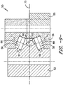
- the line contact rolling elements 56, 58 correspond to a first and second plurality of tapered rolling elements 76, 78.
- the inner and outer races 52, 54 are segments of cones and the rolling elements 56, 58 are tapered so that the conical surfaces of the races 52, 54 and the rolling element axes, if projected, would meet at a common point on the main axis of the bearing 50.
- This geometry prevents sliding motion between the rolling elements 56, 58 within the outer and inner races 52, 54.
- reference lines 57, 59 drawn through the rolling element axes are projected and converge at common point 84 of the pitch bearing 50.
- the surfaces of the races and rolling elements also converge on the same point.
- the taper angle 87 is designed and chosen to minimize slip of the tapered rolling elements 56, 58. More specifically, in certain embodiments, the taper angle 87 may include angles ranging from about 0.25° to about 6°.
- each of the plurality of line contact rolling elements 56, 58 defines a predetermined contact angle 80, 82. More specifically, a first predetermined contact angle 80 is defined as the angle between a reference line 73 extending perpendicular to a longitudinal axis 57 of one of the first plurality of line contact rolling elements 56 and a reference line 75 extending parallel to a horizontal plane of the pitch bearing 50. Similarly, a second predetermined contact angle 82 is defined as the angle between a reference line 74 extending perpendicular to a longitudinal axis 59 of one of the second plurality of line contact rolling elements 58 and a reference line 75 extending parallel to a horizontal plane of the pitch bearing 50.
- the predetermined contact angles 80, 82 may include any non-0° angles and non-90° angles.
- the predetermined contact angles 80, 82 may include angles between 0 degrees (°) and 90°.
- the predetermined contact angles 80, 82 may include angles greater than 90° angles.
- first and second contact angles 80, 82 may be the same angle or different angles. Specifically, as the contact angle approaches zero degrees, the corresponding rolling elements may be better equipped to handle radial loads whereas, as the contact angle approaches ninety degrees, the corresponding rolling elements may be better equipped to handle axial loads.
- each row of rolling elements 56, 58 may be stiffer in a given direction, such as by configuring the first plurality of rolling elements 56 to be axially stiffer (e.g., by selecting the first contact angle 80 to be closer to 90 degrees) and the second plurality of rolling elements 58 to be radially stiffer (e.g., by selecting the second contact angle 82 to be closer to 0 degrees).
- the bearings described herein are capable of achieving required radial, axial, and moment loading with just two rows of line contact rolling elements, it should further be understood that additional rows may also be utilized as desired.
- the pitch bearing 50 may further include at least one additional plurality of rolling elements 65.
- the pitch bearing 50 may also include a raceway rib 68 at least partially separating the first raceway 70 from the second raceway 72.
- the raceway rib 68 may form an extension of the outer race 52.
- the raceway rib 68 may correspond to a radial projection of the outer race 52 that extends between the line contact rolling elements 56, 58.
- the raceway rib 68 may be configured to form an extension of the inner race 54.
- the raceway rib 68 may correspond to a radial projection of the inner race 54 configured to extend between the rolling elements 56, 58.
- each row may be spaced apart circumferentially from one another using cages and/or spacers.
- one or more cages 90 may be arranged with the line contact rolling elements 56, 58 to maintain the spacing thereof.
- bearing configuration(s) shown in FIGS. 7-10 may be utilized with any other suitable wind turbine bearing(s).
- the bearing configuration(s) may be utilized within the yaw bearing 35 of the wind turbine 10.
Landscapes
- Engineering & Computer Science (AREA)
- General Engineering & Computer Science (AREA)
- Mechanical Engineering (AREA)
- Life Sciences & Earth Sciences (AREA)
- Sustainable Development (AREA)
- Sustainable Energy (AREA)
- Chemical & Material Sciences (AREA)
- Combustion & Propulsion (AREA)
- Physics & Mathematics (AREA)
- Fluid Mechanics (AREA)
- Wind Motors (AREA)
- Rolling Contact Bearings (AREA)
Abstract
Description
- The present subject matter relates generally to wind turbines and, more particularly, to a pitch bearing for a wind turbine utilizing line contact rolling elements.
- Wind power is considered one of the cleanest, most environmentally friendly energy sources presently available, and wind turbines have gained increased attention in this regard. A modern wind turbine typically includes a tower, generator, gearbox, nacelle, and one or more rotor blades. The rotor blades capture kinetic energy from wind using known airfoil principles and transmit the kinetic energy through rotational energy to turn a shaft coupling the rotor blades to a gearbox, or if a gearbox is not used, directly to the generator. The generator then converts the mechanical energy to electrical energy that may be deployed to a utility grid.
- Further, the wind turbine may include various bearings to facilitate rotation of its various components. Two examples of such bearings include pitch bearings and yaw bearings. More specifically, yaw bearings are configured to rotate the nacelle with respect to the tower as a function of the incoming wind. In addition, pitch bearings are arranged between a blade root of the rotor blades and the hub. Therefore, the pitch bearings rotate or pitch the rotor blades with respect to the incoming wind.
- Such bearings generally include an outer race, an inner race rotatable relative to the outer race, and a plurality of rolling elements therebetween. Many wind turbine bearings include point contact rolling elements,
e.g. ball bearings 1, such as those illustrated inFIG. 1 . Alternatively, as shown inFIG. 2 , some wind turbine bearings may include line contact rolling elements, such as cylindricalrolling elements 2, having a 0° and 90° contact angle configuration. - Conventional line contact rolling elements typically include the rolling elements arranged in a 0° and 90° contact angle configuration. More specifically, as shown in
FIG. 3 , a partial, cross-sectional view of a line contact rolling element bearing 3 according to conventional construction is illustrated. As shown, the line contact rolling element bearing 3 includes anouter race 7 and aninner race 8 rotatable relative to theouter race 7 via a plurality of linecontact rolling elements 4, 5, 6. More specifically, as shown, the upper and lower linecontact rolling elements 4, 5 have a 90° contact angle, whereas the middle line contact rolling element 6 has a 0° contact angle. - In such configurations, the rolling elements having a 90° contact angle experience relative sliding therebetween as well as with raceway in order to function. Successful utilization of line contact rolling elements in a 90° contact angle configuration typically relies on operation in lubrication lambda regimes greater than one such that the relative sliding is not detrimental to bearing performance. However, wind turbine pitch bearings experience lambda ratios approaching zero. Thus, when line contact rolling element bearings are used as pitch bearings, such sliding can scuff and wear interface surfaces, generating heat and debris inside the bearing.
- Accordingly, a pitch bearing having line contact rolling elements that addresses the aforementioned issues would be welcomed in the technology. In particular, a pitch bearing with less than three rows of line contact rolling elements would be beneficial.
- Various aspects and advantages of the invention will be set forth in part in the following description, or may be clear from the description, or may be learned through practice of the invention.
- In one aspect, the present disclosure is directed to a pitch bearing for coupling a rotor blade to a hub of a wind turbine. The pitch bearing includes an outer race configured to be coupled to the hub, an inner race rotatable relative to the outer race and configured to be coupled to the rotor blade, and a first plurality of line contact rolling elements. The outer race defines a first outer raceway wall and the inner race defines a first inner raceway wall. The first plurality of line contact rolling elements is disposed between the first inner and outer raceway walls. Each of the plurality of line contact rolling elements defines a predetermined contact angle. The predetermined contact angle is defined as an angle between a reference line extending perpendicular to a longitudinal axis of one of the plurality of line contact rolling elements and a reference line extending parallel to a horizontal plane of the pitch bearing. Further, the predetermined contact angle includes angles between 0 degrees (°) and 90°.
- In one embodiment, the outer race may further define a second outer raceway wall and the inner race may define a second inner raceway wall. In such embodiments, the pitch bearing may include a second plurality of line contact rolling elements disposed between the second inner and outer raceway walls.
- In another embodiment, the first and second plurality of line contact rolling elements may include cylindrical rolling elements.
- Alternatively, the first and second plurality of line contact rolling elements may include tapered rolling elements. In such embodiments, reference lines extending parallel to the longitudinal axes of the first and second plurality of tapered rolling elements may converge at a common point of the pitch bearing and define a taper angle. More specifically, in certain embodiments, the inner and outer races may be segments of cones with the rolling elements being tapered so that the conical surfaces of the races and the rolling element axes, if projected, would meet at the same common point on the main axis of the bearing. The convergence of the surfaces of the races and rolling elements defines the taper angle. For example, in certain embodiments, the taper angle may include angles ranging from about 0.25° to about 6°.
- In yet another embodiment, the pitch bearing may further include at least one additional plurality of rolling elements. In still a further embodiment, the pitch bearing may also include a raceway rib extending between the first and second plurality of rolling elements.
- In another aspect, the present disclosure is directed to a pitch bearing for coupling a rotor blade to a hub of a wind turbine. The pitch bearing includes an outer race configured to be coupled to the hub, an inner race rotatable relative to the outer race and configured to be coupled to the rotor blade, and a first plurality of line contact rolling elements. The outer race defines a first outer raceway wall and the inner race defines a first inner raceway wall. The first plurality of line contact rolling elements is disposed between the first inner and outer raceway walls. Each of the plurality of line contact rolling elements defines a predetermined contact angle. The predetermined contact angle is defined as an angle between a reference line extending perpendicular to a longitudinal axis of one of the plurality of line contact rolling elements and a reference line extending parallel to a horizontal plane of the pitch bearing. Further, the predetermined contact angle includes non-0° angles and non-90° angles. It should be understood that the pitch bearing may further include any of the additional features described herein.
- In yet another aspect, the present disclosure is directed to a slewing ring bearing. The slewing ring includes an outer race, an inner race rotatable relative to the outer race, and a plurality of line contact rolling elements. The inner race is positioned relative to the outer race such that at least one raceway is defined between the inner and outer races. The plurality of line contact rolling elements extends circumferentially around the raceway. Each of the plurality of line contact rolling elements defines a predetermined contact angle. The predetermined contact angle is defined as an angle between a reference line extending perpendicular to a longitudinal axis of one of the plurality of line contact rolling elements and a reference line extending parallel to a horizontal plane of the pitch bearing. Further, the predetermined contact angle includes non-0° angles and non-90° angles. It should be understood that the slewing ring bearing may further include any of the additional features described herein.
- Various features, aspects and advantages of the present invention will be further supported and described with reference to the following description and appended claims. The accompanying drawings, which are incorporated in and constitute a part of this specification, illustrate embodiments of the invention and, together with the description, serve to explain the principles of the invention.
- In the drawings:
-
FIG. 1 illustrates a point contact rolling element according to conventional construction; -
FIG. 2 illustrates a line contact rolling element according to conventional construction; -
FIG. 3 illustrates a partial, cross-sectional view of a line contact rolling element bearing according to conventional construction; -
FIG. 4 illustrates a perspective view of one embodiment of a wind turbine according to the present disclosure; -
FIG. 5 illustrates a perspective view of one of the rotor blades of the wind turbine shown inFIG. 4 ; -
FIG. 6 illustrates a perspective, internal view of the nacelle of the wind turbine shown inFIG. 4 ; -
FIG. 7 illustrates a cross-sectional view of one embodiment of a rotor blade coupled to a wind turbine hub via a pitch bearing according to the present disclosure; -
FIG. 8 illustrates a close-up, cross-sectional view of a portion of the pitch bearing illustrated inFIG. 7 ; -
FIG. 9 illustrates a close-up, cross-sectional view of an another embodiment of a portion of the pitch bearing according to the present disclosure; -
FIG. 10 illustrates a close-up, cross-sectional view of an yet another embodiment of a portion of the pitch bearing according to the present disclosure, particularly illustrating cages configured with the rolling elements; and -
FIG. 11 illustrates a close-up, cross-sectional view of an yet another embodiment of a portion of the pitch bearing according to the present disclosure, particularly illustrating a three-row rolling element configuration. - Reference now will be made in detail to embodiments of the invention, one or more examples of which are illustrated in the drawings. Each example is provided by way of explanation of the invention, not limitation of the invention. In fact, it will be apparent to those skilled in the art that various modifications and variations can be made in the present invention without departing from the scope or spirit of the invention. For instance, features illustrated or described as part of one embodiment can be used with another embodiment to yield a still further embodiment. Thus, it is intended that the present invention covers such modifications and variations as come within the scope of the appended claims and their equivalents.
- In general, the present subject matter is directed to bearing configurations for a wind turbine. In several embodiments, a pitch bearing of the wind turbine may include first and second rows of line contact rolling elements arranged between inner and outer races of the bearing. It should be appreciated that the disclosed pitch bearings have been uniquely configured to handle the dynamic loading of a wind turbine. Specifically, due to erratic moment loading and the fact that each pitch bearing is mounted directly to a relatively flexible rotor blade, pitch bearings must be equipped to handle axial and radial loads that can vary significantly with time. As will be described below, the disclosed bearings provide for non-0° and non-90° contact angles, thereby reducing the resultant loads applied through each rolling element and eliminating sliding therebetween. Accordingly, each rolling element may deflect less and, thus, may retain more of an overall share of the entire load, thereby decreasing the stress on the bearing.
- It should also be appreciated that, although the present subject matter will be generally described herein with reference to pitch bearings, the disclosed bearing configurations may be utilized within any suitable wind turbine bearing. For instance, yaw bearings are often subject to dynamic loading during operation of a wind turbine. Thus, the disclosed bearing configurations may also be implemented within the yaw bearing of a wind turbine to reduce stresses within the bearing.
- Referring now to the drawings,
FIG. 4 illustrates a perspective view of one embodiment of awind turbine 10 according to the present disclosure. As shown, thewind turbine 10 generally includes atower 12, anacelle 14 mounted on thetower 12, and arotor 16 coupled to thenacelle 14. Therotor 16 includes arotatable hub 18 and at least onerotor blade 20 coupled to and extending outwardly from thehub 18. For example, in the illustrated embodiment, therotor 16 includes threerotor blades 20. However, in an alternative embodiment, therotor 16 may include more or less than threerotor blades 20. Eachrotor blade 20 may be spaced about thehub 18 to facilitate rotating therotor 16 to enable kinetic energy to be transferred from the wind into usable mechanical energy, and subsequently, electrical energy. For instance, thehub 18 maybe rotatably coupled to an electric generator 25 (FIG. 5 ) positioned within thenacelle 14 to permit electrical energy to be produced. - Referring now to
FIG. 5 , a perspective view of one of therotor blades 20 shown inFIG. 4 is illustrated in accordance with aspects of the present subject matter. As shown, therotor blade 20 includes ablade root 22 configured for mounting therotor blade 20 to thehub 18 of the wind turbine 10 (FIG. 4 ) and ablade tip 24 disposed opposite theblade root 22. Abody 26 of therotor blade 20 may extend lengthwise between theblade root 22 and theblade tip 24 and may generally serve as the outer shell of therotor blade 20. As is generally understood, thebody 26 may define an aerodynamic profile (e.g., by defining an airfoil shaped cross-section, such as a symmetrical or cambered airfoil-shaped cross-section) to enable therotor blade 20 to capture kinetic energy from the wind using known aerodynamic principles. Thus, thebody 26 may generally include apressure side 28 and asuction side 30 extending between aleading edge 32 and a trailingedge 34. Additionally, therotor blade 20 may have aspan 36 defining the total length of thebody 26 between theblade root 22 and theblade tip 24 and achord 38 defining the total length of thebody 26 between theleading edge 32 and the trailingedge 34. As is generally understood, thechord 38 may vary in length with respect to thespan 26 as thebody 26 extends from theblade root 22 to theblade tip 24. - Moreover, as shown, the
rotor blade 20 may also include a plurality of T-bolts orroot attachment assemblies 40 for coupling theblade root 20 to thehub 18 of thewind turbine 10. In general, eachroot attachment assembly 40 may include abarrel nut 42 mounted within a portion of theblade root 22 and aroot bolt 44 coupled to and extending from thebarrel nut 42 so as to project outwardly from aroot end 46 of theblade root 22. By projecting outwardly from theroot end 46, theroot bolts 44 may generally be used to couple theblade root 22 to the hub 18 (e.g., via one of the pitch bearings 50), as will be described in greater detail below. - Referring now to
FIG. 6 , a simplified, internal view of one embodiment of thenacelle 14 of thewind turbine 10 shown inFIG. 4 is illustrated. As shown, thegenerator 25 may be disposed within thenacelle 14. In general, thegenerator 25 may be coupled to therotor 16 of thewind turbine 10 for generating electrical power from the rotational energy generated by therotor 16. For example, therotor 16 may include arotor shaft 27 coupled to thehub 18 for rotation therewith. Thegenerator 25 may then be coupled to therotor shaft 27 such that rotation of therotor shaft 27 drives thegenerator 25. For instance, in the illustrated embodiment, thegenerator 25 includes agenerator shaft 29 rotatably coupled to therotor shaft 27 through agearbox 31. However, in other embodiments, it should be appreciated that thegenerator shaft 29 may be rotatably coupled directly to therotor shaft 27. Alternatively, thegenerator 25 may be directly rotatably coupled to the rotor shaft 27 (often referred to as a "direct-drive wind turbine"). - Referring still to
FIG. 6 , thewind turbine 10 may include numerous slewing ring bearings for allowing rotation of various components of thewind turbine 10. For example, it should be appreciated that, as used herein, the term "slewing ring bearing" may be used to refer to the yaw bearing 35 of thewind turbine 10 and/or one of thepitch bearings 50 of thewind turbine 10. Similarly, it should be appreciated that the slewingring bearings ring bearings - Additionally, the
wind turbine 10 may include one or moreyaw drive mechanisms 33 mounted to and/or through abedplate 15 positioned atop thewind turbine tower 12. Specifically, eachyaw drive mechanism 33 may be mounted to and/or through thebedplate 15 so as to engage the yaw bearing 35 coupled between thebedplate 15 and thetower 12 of thewind turbine 10. Theyaw bearing 35 may be mounted to thebed plate 15 such that, as theyaw bearing 35 rotates about a yaw axis (not shown) of thewind turbine 10, thebedplate 15 and, thus, thenacelle 14 are similarly rotated about the yaw axis. It should be appreciated that, although the illustratedwind turbine 10 is shown as including two yaw drive mechanisms 232, thewind turbine 10 may generally include any suitable number of yaw drive mechanisms 232. - Referring still to
FIG. 6 , thewind turbine 10 may also include a plurality of pitch bearings 50 (one of which is shown), with each pitch bearing 50 being coupled between thehub 18 and one of therotor blades 20. As will be described below, thepitch bearings 50 may be configured to allow eachrotor blade 20 to be rotated about its pitch axis 39 (e.g., via a pitch adjustment mechanism 45), thereby allowing the orientation of eachblade 20 to be adjusted relative to the direction of the wind. - In general, it should be appreciated that the pitch and
yaw drive mechanisms such mechanisms pitch adjustment mechanism 45 may include a pitch drive motor 37 (e.g., an electric motor), apitch drive gearbox 41, and apitch drive pinion 43. In such an embodiment, thepitch drive motor 37 may be coupled to thepitch drive gearbox 41 so that themotor 37 imparts mechanical force to thegearbox 41. Similarly, thegearbox 41 may be coupled to thepitch drive pinion 43 for rotation therewith. Thepinion 43 may, in turn, be in rotational engagement with theinner race 54. - Referring now to
FIGS. 7 and8 , partial, cross-sectional views of therotor blade 20 shown inFIG. 5 are illustrated, particularly illustrating therotor blade 20 mounted onto thehub 18 via one of thepitch bearings 50 according to the present disclosure. As shown, the pitch bearing 50 includes anouter bearing race 52, aninner bearing race 54, and a plurality of linecontact rolling elements 56, 58 (e.g., a first plurality of rollingelements 56 and a second plurality of rolling elements 58) disposed between the outer andinner races FIGS. 8 and10 , the first and second plurality of linecontact rolling elements rolling elements FIG. 9 , the first and second plurality of linecontact rolling elements elements - Further, as shown, the
outer race 52 may generally be configured to be mounted to ahub flange 60 of thehub 18 using a plurality ofhub bolts 62 and/or other suitable fastening mechanisms. Similarly, theinner race 54 may be configured to be mounted to theblade root 22 using theroot bolts 44 of theroot attachment assemblies 40. For example, as shown inFIG. 7 , eachroot bolt 44 may extend between afirst end 64 and asecond end 66. Thefirst end 64 may be configured to be coupled to a portion of theinner race 54, such as by coupling thefirst end 64 to theinner race 54 using an attachment nut and/or other suitable fastening mechanism. Thesecond end 66 of eachroot bolt 44 may be configured to be coupled to theblade root 22 via thebarrel nut 42 of eachroot attachment assembly 40. - As is generally understood, the
inner race 54 may be configured to be rotated relative to the outer race 52 (via the rollingelements 56, 58) to allow the pitch angle of eachrotor blade 20 to be adjusted. As shown inFIG. 7 , such relative rotation of the outer andinner races pitch adjustment mechanism 45 mounted within a portion of thehub 18. For example, as shown inFIG. 7 , a plurality ofgear teeth 55 may be formed along the inner circumference of theinner race 54 of the pitch bearing 50, with thegear teeth 47 being configured to mesh withcorresponding gear teeth 47 formed on thepinion 78. Thus, due to meshing of thegear teeth pitch drive pinion 43 results in rotation of theinner race 54 relative to theouter race 52 via the plurality of rollingelements rotor blade 20 relative to thehub 18. - Referring now to
FIG. 8 , a close-up, cross-sectional view of a portion of the pitch bearing 50 shown inFIG. 7 is illustrated in accordance with aspects of the present subject matter. As shown, the linecontact rolling elements outer races first raceway 70 is defined between the inner andouter races elements 56 and asecond raceway 72 is defined between the inner andouter races elements 58. In such an embodiment, eachraceway inner races - In addition, as shown, the line
contact rolling elements rolling elements outer races elements races bearing 50. This geometry prevents sliding motion between the rollingelements inner races FIG. 8 ,reference lines common point 84 of thepitch bearing 50. In addition, the surfaces of the races and rolling elements also converge on the same point. As such, thetaper angle 87 is designed and chosen to minimize slip of the taperedrolling elements taper angle 87 may include angles ranging from about 0.25° to about 6°. - Referring still to
FIG. 8 , each of the plurality of linecontact rolling elements predetermined contact angle predetermined contact angle 80 is defined as the angle between areference line 73 extending perpendicular to alongitudinal axis 57 of one of the first plurality of linecontact rolling elements 56 and areference line 75 extending parallel to a horizontal plane of thepitch bearing 50. Similarly, a secondpredetermined contact angle 82 is defined as the angle between areference line 74 extending perpendicular to alongitudinal axis 59 of one of the second plurality of linecontact rolling elements 58 and areference line 75 extending parallel to a horizontal plane of thepitch bearing 50. Further, the predetermined contact angles 80, 82 may include any non-0° angles and non-90° angles. For example, in one embodiment, the predetermined contact angles 80, 82 may include angles between 0 degrees (°) and 90°. In addition, the predetermined contact angles 80, 82 may include angles greater than 90° angles. - It should also be appreciated that first and second contact angles 80, 82 may be the same angle or different angles. Specifically, as the contact angle approaches zero degrees, the corresponding rolling elements may be better equipped to handle radial loads whereas, as the contact angle approaches ninety degrees, the corresponding rolling elements may be better equipped to handle axial loads. Thus, by differing the contact angles 80, 82, each row of rolling
elements elements 56 to be axially stiffer (e.g., by selecting thefirst contact angle 80 to be closer to 90 degrees) and the second plurality of rollingelements 58 to be radially stiffer (e.g., by selecting thesecond contact angle 82 to be closer to 0 degrees). - Even though the bearings described herein are capable of achieving required radial, axial, and moment loading with just two rows of line contact rolling elements, it should further be understood that additional rows may also be utilized as desired. For example, as shown in
FIG. 11 , the pitch bearing 50 may further include at least one additional plurality of rollingelements 65. - Referring generally to
FIGS. 8-10 , the pitch bearing 50 may also include araceway rib 68 at least partially separating thefirst raceway 70 from thesecond raceway 72. In several embodiments, theraceway rib 68 may form an extension of theouter race 52. For instance, as shown in the cross-sectional view ofFIG. 8 , theraceway rib 68 may correspond to a radial projection of theouter race 52 that extends between the linecontact rolling elements raceway rib 68 may be configured to form an extension of theinner race 54. For instance, theraceway rib 68 may correspond to a radial projection of theinner race 54 configured to extend between the rollingelements - It should be appreciated that the rolling
elements FIG. 10 , one ormore cages 90 may be arranged with the linecontact rolling elements - It should also be appreciated that the bearing configuration(s) shown in
FIGS. 7-10 may be utilized with any other suitable wind turbine bearing(s). For instance, in several embodiments, the bearing configuration(s) may be utilized within the yaw bearing 35 of thewind turbine 10. - This written description uses examples to disclose the invention, including the preferred mode, and also to enable any person skilled in the art to practice the invention, including making and using any devices or systems and performing any incorporated methods. The patentable scope of the invention is defined by the claims, and may include other examples that occur to those skilled in the art. Such other examples are intended to be within the scope of the claims if they include structural elements that do not differ from the literal language of the claims, or if they include equivalent structural elements with insubstantial differences from the literal languages of the claims.
- Various aspects and embodiments of the present invention are defined by the following numbered clauses:
- 1. A pitch bearing for coupling a rotor blade to a hub of a wind turbine, the pitch bearing comprising:
- an outer race configured to be coupled to the hub, the outer race defining a first outer raceway wall;
- an inner race rotatable relative to the outer race and configured to be coupled to the rotor blade, the inner race defining a first inner raceway wall; and,
- a first plurality of line contact rolling elements disposed between the first inner and outer raceway walls,
- 2. The pitch bearing of
clause 1, wherein the outer race defines a second outer raceway wall and the inner race defines a second inner raceway wall, the pitch bearing further comprising a second plurality of line contact rolling elements disposed between the second inner and outer raceway walls. - 3. The pitch bearing of any preceding clause, wherein the first and second plurality of line contact rolling elements comprise cylindrical rolling elements.
- 4. The pitch bearing of any preceding clause, wherein the first and second plurality of line contact rolling elements comprise tapered rolling elements.
- 5. The pitch bearing of any preceding clause, wherein reference lines extending parallel to the longitudinal axes of the first and second plurality of tapered rolling elements converge at a common point of the pitch bearing and define a taper angle, the taper angle configured to minimize slip of the tapered rolling elements.
- 6. The pitch bearing of any preceding clause, wherein the taper angle comprises angles ranging from about 0.25° to about 6°.
- 7. The pitch bearing of any preceding clause, further comprising at least one additional plurality of rolling elements.
- 8. The pitch bearing of any preceding clause, further comprising a raceway rib extending between the first and second plurality of rolling elements.
- 9. A pitch bearing for coupling a rotor blade to a hub of a wind turbine, the pitch bearing comprising:
- an outer race configured to be coupled to the hub, the outer race defining a first outer raceway wall;
- an inner race rotatable relative to the outer race and configured to be coupled to the rotor blade, the inner race defining a first inner raceway wall; and,
- a first plurality of line contact rolling elements disposed between the first inner and outer raceway walls,
- 10. The pitch bearing of any preceding clause, wherein the outer race defines a second outer raceway wall and the inner race defines a second inner raceway wall, the pitch bearing further comprising a second plurality of line contact rolling elements disposed between the second inner and outer raceway walls.
- 11. The pitch bearing of any preceding clause, wherein the first and second plurality of line contact rolling elements comprise cylindrical rolling elements.
- 12. The pitch bearing of any preceding clause, wherein the first and second plurality of line contact rolling elements comprise tapered rolling elements.
- 13. The pitch bearing of any preceding clause, wherein reference lines extending parallel to the longitudinal axes of the first and second plurality of tapered rolling elements converge at a common point of the pitch bearing and define a taper angle, the taper angle configured to minimize slip of the tapered rolling elements.
- 14. The pitch bearing of any preceding clause, wherein the taper angle comprises angles ranging from about 0.25° to about 6°.
- 15. The pitch bearing of any preceding clause, further comprising at least one additional plurality of rolling elements.
- 16. The pitch bearing of any preceding clause, further comprising a raceway rib extending between the first and second plurality of rolling elements.
- 17. A slewing ring bearing for a wind turbine, the slewing ring bearing comprising:
- an outer race;
- an inner race rotatably coupled to the outer race, the inner race being positioned relative to the outer races such that at least one raceway is defined between the inner and outer races; and,
- a plurality of line contact rolling elements extending circumferentially around the raceway, each of the plurality of line contact rolling elements defining a predetermined contact angle, the predetermined contact angle defined as an angle between a reference line extending perpendicular to a longitudinal axis of one of the plurality of line contact rolling elements and a reference line extending parallel to a horizontal plane of the pitch bearing, the predetermined contact angle comprising non-0° angles and non-90° angles.
- 18. The slewing ring bearing of any preceding clause, wherein the slewing ring bearing comprises at least one of a pitch bearing or a yaw bearing of a wind turbine.
- 19. The slewing ring bearing of any preceding clause, wherein the plurality of line contact rolling elements comprise at least one of cylindrical rolling elements or tapered rolling elements.
- 20. The slewing ring bearing of any preceding clause, wherein reference lines extending parallel to the longitudinal axes of the first and second plurality of line contact rolling elements converge at a common point of the bearing and define a taper angle, the taper angle configured to minimize slip of the plurality of line contact rolling elements, wherein the taper angle comprises angles ranging from about 0.25° to about 6°.
Claims (13)
- A pitch bearing (50) for coupling a rotor blade (20) to a hub (18) of a wind turbine (10), the pitch bearing (50) comprising:an outer race (52) configured to be coupled to the hub (18), the outer race (52) defining a first outer raceway wall;an inner race (54) rotatable relative to the outer race (52) and configured to be coupled to the rotor blade (20), the inner race (54) defining a first inner raceway wall; and,a first plurality of line contact rolling elements (56, 58) disposed between the first inner and outer raceway walls,wherein each of the plurality of line contact rolling elements (56, 58) defines a predetermined contact angle (80, 82), the predetermined contact angle (80, 82) defined as an angle between a reference line (73, 74) extending perpendicular to a longitudinal axis of one of the plurality of line contact rolling elements (56, 58) and a reference line (75) extending parallel to a horizontal plane of the pitch bearing (50), the predetermined contact angle (80, 82) comprising angles between 0 degrees (°) and 90°.
- The pitch bearing (50) of claim 1, wherein the outer race (52) defines a second outer raceway wall and the inner race (54) defines a second inner raceway wall, the pitch bearing (50) further comprising a second plurality of line contact rolling elements (56, 58) disposed between the second inner and outer raceway walls.
- The pitch bearing (50) of any preceding claim, wherein the first and second plurality of line contact rolling elements (56, 58) comprise cylindrical rolling elements (86, 88).
- The pitch bearing (50) of any preceding claim, wherein the first and second plurality of line contact rolling elements (56, 58) comprise tapered rolling elements (76, 78).
- The pitch bearing (50) of claim 4, wherein reference lines (73, 74) extending parallel to the longitudinal axes of the first and second plurality of tapered rolling elements (56, 58) converge at a common point (84) of the pitch bearing (50) and define a taper angle (87), the taper angle (87) configured to minimize slip of the tapered rolling elements (56, 58).
- The pitch bearing (50) of claim 5, wherein the taper angle (87) comprises angles ranging from about 0.25° to about 6°.
- The pitch bearing (50) of any of the preceding claims, further comprising at least one additional plurality of rolling elements (56, 58).
- The pitch bearing (50) of any preceding claim, further comprising a raceway rib (68) extending between the first and second plurality of rolling elements (56, 58).
- A slewing ring bearing for a wind turbine (10), the slewing ring bearing comprising:an outer race (52);an inner race (54) rotatably coupled to the outer race (52), the inner race (54) being positioned relative to the outer race (52)s such that at least one raceway is defined between the inner and outer race (52)s; and,a plurality of line contact rolling elements (56, 58) extending circumferentially around the raceway, each of the plurality of line contact rolling elements (56, 58) defining a predetermined contact angle (80, 82), the predetermined contact angle (80, 82) defined as an angle between a reference line (73, 74) extending perpendicular to a longitudinal axis of one of the plurality of line contact rolling elements (56, 58) and a reference line (75) extending parallel to a horizontal plane of the pitch bearing (50), the predetermined contact angle (80, 82) comprising non-0° angles and non-90° angles.
- The slewing ring bearing of claim 9, wherein the slewing ring bearing comprises at least one of a pitch bearing (50) or a yaw bearing of a wind turbine (10).
- The slewing ring bearing of claims 9 or 10, wherein the plurality of line contact rolling elements (56, 58) comprise at least one of cylindrical rolling elements (86, 88) or tapered rolling elements (76, 78).
- The slewing ring bearing of claim 11, wherein reference lines (73, 73) extending parallel to the longitudinal axes of the first and second plurality of line contact rolling elements (56, 58) converge at a common point (84) of the bearing and define a taper angle (87), the taper angle (87) configured to minimize slip of the plurality of line contact rolling elements (56, 58).
- The slewing ring bearing of claim 12, wherein the taper angle (87) comprises angles ranging from about 0.25° to about 6°.
Applications Claiming Priority (1)
| Application Number | Priority Date | Filing Date | Title |
|---|---|---|---|
| US15/783,590 US10677290B2 (en) | 2017-10-13 | 2017-10-13 | Wind turbine pitch bearing with line contact rolling elements |
Publications (2)
| Publication Number | Publication Date |
|---|---|
| EP3470671A1 true EP3470671A1 (en) | 2019-04-17 |
| EP3470671B1 EP3470671B1 (en) | 2023-03-22 |
Family
ID=63722217
Family Applications (1)
| Application Number | Title | Priority Date | Filing Date |
|---|---|---|---|
| EP18198194.5A Active EP3470671B1 (en) | 2017-10-13 | 2018-10-02 | Wind turbine pitch bearing with line contact rolling elements |
Country Status (5)
| Country | Link |
|---|---|
| US (1) | US10677290B2 (en) |
| EP (1) | EP3470671B1 (en) |
| CN (1) | CN109667733B (en) |
| DK (1) | DK3470671T3 (en) |
| ES (1) | ES2947947T3 (en) |
Families Citing this family (3)
| Publication number | Priority date | Publication date | Assignee | Title |
|---|---|---|---|---|
| DE202018100216U1 (en) * | 2018-01-16 | 2019-04-17 | Liebherr-Components Biberach Gmbh | Multi-row rolling bearing |
| EP3767118B1 (en) * | 2019-07-19 | 2022-11-23 | Siemens Gamesa Renewable Energy A/S | Wind turbine rotor blade pitch bearing |
| US11725698B1 (en) * | 2022-05-20 | 2023-08-15 | General Electric Renovables Espana, S.L. | Method for manufacturing slewing ring bearing components having an integral stiffener |
Citations (7)
| Publication number | Priority date | Publication date | Assignee | Title |
|---|---|---|---|---|
| US20030086631A1 (en) * | 2001-10-10 | 2003-05-08 | Barbara Faltus | Roller bearing |
| DE20306897U1 (en) * | 2003-05-05 | 2004-09-09 | Ab Skf | Rolling bearing for wind power plant, for example, has segmented flange with run-on face which has stepped construction in circumferential direction, whereby all steps are orientated in same direction |
| EP1519058A2 (en) * | 2003-09-23 | 2005-03-30 | Ab Skf | Bearing for the rotor of a wind energy plant |
| EP1741940A1 (en) * | 2005-07-08 | 2007-01-10 | Defontaine | Barrel-shaped bearing |
| DE102008049811A1 (en) * | 2008-09-30 | 2010-04-01 | Schaeffler Kg | Rotor bearing for a wind turbine, comprising a double, multi-row roller bearing |
| US20100244454A1 (en) * | 2007-08-31 | 2010-09-30 | Schaeffler Technologies Gmbh & Co., Kg | Rotor bearing for a wind turbine |
| DE102014205816A1 (en) * | 2014-03-28 | 2015-10-01 | Aktiebolaget Skf | Bearing arrangement for rotatably supporting a turbine blade on a turbine hub |
Family Cites Families (50)
| Publication number | Priority date | Publication date | Assignee | Title |
|---|---|---|---|---|
| GB648534A (en) * | 1946-03-04 | 1951-01-10 | Meyer Schlioma Frenkel | Angular contact bearings and taper roller bearings |
| US3744863A (en) * | 1971-09-10 | 1973-07-10 | Rollway Bearing Co Inc | Cylindrical roller conical bearing |
| US4166659A (en) * | 1977-11-04 | 1979-09-04 | General Electric Company | Thrust bearing assembly |
| SE410992B (en) * | 1978-04-11 | 1979-11-19 | Skf Ab | ROLLING STOCK |
| DE3520814A1 (en) * | 1985-06-11 | 1986-12-11 | INA Wälzlager Schaeffler KG, 8522 Herzogenaurach | Cage for angular-contact roller bearings |
| US5711738A (en) * | 1995-07-24 | 1998-01-27 | Nsk Ltd. | Conical roller bearing for supporting a pinion shaft of differential gear |
| JP4040160B2 (en) * | 1998-03-20 | 2008-01-30 | Ntn株式会社 | Double row tapered roller bearing |
| DE19962978C1 (en) * | 1999-12-24 | 2001-08-30 | Aloys Wobben | Wind turbine with a tower-based machine head |
| DE10102255A1 (en) * | 2001-01-19 | 2002-08-01 | Aloys Wobben | Wind turbine with a hollow shaft for rotor hub and generator |
| CN2508047Y (en) * | 2001-03-07 | 2002-08-28 | 俞大邦 | Pure rolling bearing |
| DE10256855A1 (en) | 2002-12-05 | 2004-06-17 | Ab Skf | Procedure for assembling a double row tapered roller bearing |
| DE102004055227A1 (en) * | 2004-11-17 | 2006-05-18 | Fag Kugelfischer Ag & Co. Ohg | Tapered roller bearings |
| CN2886183Y (en) * | 2006-02-13 | 2007-04-04 | 襄阳汽车轴承股份有限公司 | Automobile axle driving bevel gear supporting bearing |
| DE102007008167C5 (en) * | 2007-02-14 | 2016-07-07 | Nordex Energy Gmbh | Wind turbine with a rotor hub |
| DE102007019482A1 (en) * | 2007-04-25 | 2008-11-06 | Schaeffler Kg | Multi-row slewing bearings, in particular axial-radial bearings for main bearing of the rotor shaft of a wind turbine |
| JP5040552B2 (en) * | 2007-09-21 | 2012-10-03 | 株式会社ジェイテクト | Rolling bearing device |
| CN201258914Y (en) * | 2008-04-28 | 2009-06-17 | 洛阳斯意特轴承制造有限公司 | Angular contact ball bearing special for liquid eddy-current speed reducer |
| CN101684841B (en) * | 2008-09-26 | 2011-07-20 | 上海联合滚动轴承有限公司 | Pitch bearing used on wind driven generator |
| US8459872B2 (en) * | 2008-10-10 | 2013-06-11 | General Electric Company | Bearing with alternative load path for extreme loads |
| DE102009014923C5 (en) | 2009-03-25 | 2015-07-23 | Ab Skf | Double row tapered roller bearing, in particular for supporting a rotor shaft of a wind turbine |
| US20110194937A1 (en) * | 2010-02-05 | 2011-08-11 | Rotating Composite Technologies, Llc | Preloaded bearing for rotor blade |
| EP2360383A1 (en) | 2010-02-24 | 2011-08-24 | Siemens Aktiengesellschaft | Bearing system for a wind turbine rotor |
| AT509625B1 (en) * | 2010-04-14 | 2012-02-15 | Miba Gleitlager Gmbh | BEARING ELEMENT |
| CN201913545U (en) * | 2010-08-02 | 2011-08-03 | 广东科达机电股份有限公司 | Novel double-cam type polishing and grinding head |
| EP2434150B2 (en) | 2010-09-27 | 2016-08-17 | Siemens Aktiengesellschaft | A three row roller bearing, in particular for a wind turbine |
| DK2633191T3 (en) | 2010-09-30 | 2015-06-15 | Timken Co | Windmill blade Mounting System |
| DE102010052117A1 (en) | 2010-11-17 | 2012-05-24 | Imo Holding Gmbh | Assembly as a bearing assembly for the rotating storage of machine and system parts |
| WO2012069212A1 (en) * | 2010-11-22 | 2012-05-31 | Siemens Aktiengesellschaft | Double row tapered bearing assembly and wind turbine |
| CN202012567U (en) * | 2011-02-28 | 2011-10-19 | 郭溪泉 | Main bearing device of main shaft of wind driven generator |
| EP2689153B1 (en) * | 2011-03-24 | 2017-02-08 | Aktiebolaget SKF | Angular contact roller bearing, notably used in a wind turbine. |
| EP2511521B2 (en) * | 2011-04-14 | 2021-06-16 | Siemens Gamesa Renewable Energy A/S | Pitch bearing |
| DE102011113122A1 (en) * | 2011-06-21 | 2012-12-27 | Imo Holding Gmbh | Blade bearing for a wind turbine and method for producing the same |
| EP2546512B1 (en) * | 2011-07-13 | 2016-03-02 | ALSTOM Renewable Technologies | Wind turbine rotor |
| DE112012004129B4 (en) * | 2011-10-04 | 2024-12-24 | Nabtesco Corporation | gear transmission |
| CN202412050U (en) * | 2011-12-07 | 2012-09-05 | 苏州温特金刚石滚轮有限公司 | Wind power pitch bearing diamond roller |
| US9523353B2 (en) * | 2011-12-20 | 2016-12-20 | Imo Holding Gmbh | Blade bearing or nacelle bearing of a wind turbine |
| EP2610511A1 (en) | 2011-12-28 | 2013-07-03 | Siemens Aktiengesellschaft | Cage and rolling element bearing |
| DE102012204280A1 (en) * | 2012-03-19 | 2013-09-19 | Schaeffler Technologies AG & Co. KG | Taper roller bearing for bearing differential gear basket of differential gear in motor car, has inner and outer rings provided with inner and outer raceways, respectively, where extension of outer raceway intersects with axis in point |
| CN202545571U (en) * | 2012-04-23 | 2012-11-21 | 洛阳新强联回转支承股份有限公司 | Rotary support bearing with double-row thrust conical roller structure |
| EP2669541B1 (en) | 2012-05-31 | 2015-06-24 | Siemens Aktiengesellschaft | Tapered roller bearing arrangement for a direct drive generator of a wind turbine |
| DE102012214432A1 (en) * | 2012-08-14 | 2014-06-12 | Schaeffler Technologies Gmbh & Co. Kg | Truck mixer gearbox |
| JP6039478B2 (en) * | 2013-03-25 | 2016-12-07 | ナブテスコ株式会社 | Gear transmission |
| CN103266988B (en) * | 2013-05-24 | 2015-04-22 | 北京金风科创风电设备有限公司 | Wind generating set and variable pitch driving system thereof |
| GB2514845B (en) * | 2013-06-07 | 2019-11-13 | Equinor Energy As | Wind turbine control |
| US9951815B2 (en) * | 2013-06-27 | 2018-04-24 | General Electric Company | Pitch bearing assembly with stiffener |
| US9188107B2 (en) * | 2013-08-30 | 2015-11-17 | General Electric Company | Wind turbine bearings |
| EP2871377B1 (en) * | 2013-11-07 | 2017-01-25 | Aktiebolaget SKF | Bearing unit for fluid machinery application |
| BR102014026410A2 (en) * | 2013-11-07 | 2016-10-04 | Skf Ab | bearing arrangement for fluid machinery application |
| CN204851521U (en) * | 2015-07-02 | 2015-12-09 | 国电联合动力技术有限公司 | Tidal power generation unit and become oar bearing thereof |
| EP3173642B1 (en) | 2015-11-27 | 2018-07-18 | GE Renewable Technologies Wind B.V. | Wind turbine generator with bearing system and seal |
-
2017
- 2017-10-13 US US15/783,590 patent/US10677290B2/en active Active
-
2018
- 2018-10-02 ES ES18198194T patent/ES2947947T3/en active Active
- 2018-10-02 DK DK18198194.5T patent/DK3470671T3/en active
- 2018-10-02 EP EP18198194.5A patent/EP3470671B1/en active Active
- 2018-10-12 CN CN201811188742.6A patent/CN109667733B/en active Active
Patent Citations (7)
| Publication number | Priority date | Publication date | Assignee | Title |
|---|---|---|---|---|
| US20030086631A1 (en) * | 2001-10-10 | 2003-05-08 | Barbara Faltus | Roller bearing |
| DE20306897U1 (en) * | 2003-05-05 | 2004-09-09 | Ab Skf | Rolling bearing for wind power plant, for example, has segmented flange with run-on face which has stepped construction in circumferential direction, whereby all steps are orientated in same direction |
| EP1519058A2 (en) * | 2003-09-23 | 2005-03-30 | Ab Skf | Bearing for the rotor of a wind energy plant |
| EP1741940A1 (en) * | 2005-07-08 | 2007-01-10 | Defontaine | Barrel-shaped bearing |
| US20100244454A1 (en) * | 2007-08-31 | 2010-09-30 | Schaeffler Technologies Gmbh & Co., Kg | Rotor bearing for a wind turbine |
| DE102008049811A1 (en) * | 2008-09-30 | 2010-04-01 | Schaeffler Kg | Rotor bearing for a wind turbine, comprising a double, multi-row roller bearing |
| DE102014205816A1 (en) * | 2014-03-28 | 2015-10-01 | Aktiebolaget Skf | Bearing arrangement for rotatably supporting a turbine blade on a turbine hub |
Also Published As
| Publication number | Publication date |
|---|---|
| CN109667733A (en) | 2019-04-23 |
| EP3470671B1 (en) | 2023-03-22 |
| US10677290B2 (en) | 2020-06-09 |
| US20190113077A1 (en) | 2019-04-18 |
| DK3470671T3 (en) | 2023-06-19 |
| CN109667733B (en) | 2022-12-09 |
| ES2947947T3 (en) | 2023-08-24 |
Similar Documents
| Publication | Publication Date | Title |
|---|---|---|
| US9188107B2 (en) | Wind turbine bearings | |
| US9551324B2 (en) | Pitch bearing assembly with stiffener | |
| US9951815B2 (en) | Pitch bearing assembly with stiffener | |
| US11454219B2 (en) | Rotor assembly having a pitch bearing with a stiffener ring | |
| US10794422B1 (en) | System and method for assembling a slewing ring bearing with a predetermined preload | |
| US8469664B2 (en) | Yaw bearing assembly and tower for wind turbine | |
| US11725633B2 (en) | Pitch bearing for a wind turbine | |
| EP3470671B1 (en) | Wind turbine pitch bearing with line contact rolling elements | |
| EP2937585B1 (en) | Spacer assembly for a bearing | |
| US10655610B2 (en) | Wire races for wind turbine bearings | |
| EP3112669B1 (en) | Pitch assembly for a wind turbine rotor blade | |
| US20150056078A1 (en) | Pitch bearing assembly with stiffener | |
| CN112105816A (en) | Pitch bearing for wind turbine | |
| US10598159B2 (en) | Wind turbine bearings | |
| EP3249219B1 (en) | Wind turbine bearings | |
| EP3614003B1 (en) | Ball plug retention for a slewing ring bearing | |
| US11333200B2 (en) | Method for manufacturing a pitch bearing or a yaw bearing of a wind turbine via additive manufacturing | |
| WO2018026353A1 (en) | Pitch bearing arrangement at hub of wind turbine |
Legal Events
| Date | Code | Title | Description |
|---|---|---|---|
| PUAI | Public reference made under article 153(3) epc to a published international application that has entered the european phase |
Free format text: ORIGINAL CODE: 0009012 |
|
| STAA | Information on the status of an ep patent application or granted ep patent |
Free format text: STATUS: THE APPLICATION HAS BEEN PUBLISHED |
|
| AK | Designated contracting states |
Kind code of ref document: A1 Designated state(s): AL AT BE BG CH CY CZ DE DK EE ES FI FR GB GR HR HU IE IS IT LI LT LU LV MC MK MT NL NO PL PT RO RS SE SI SK SM TR |
|
| AX | Request for extension of the european patent |
Extension state: BA ME |
|
| STAA | Information on the status of an ep patent application or granted ep patent |
Free format text: STATUS: REQUEST FOR EXAMINATION WAS MADE |
|
| 17P | Request for examination filed |
Effective date: 20191017 |
|
| RBV | Designated contracting states (corrected) |
Designated state(s): AL AT BE BG CH CY CZ DE DK EE ES FI FR GB GR HR HU IE IS IT LI LT LU LV MC MK MT NL NO PL PT RO RS SE SI SK SM TR |
|
| STAA | Information on the status of an ep patent application or granted ep patent |
Free format text: STATUS: EXAMINATION IS IN PROGRESS |
|
| 17Q | First examination report despatched |
Effective date: 20201006 |
|
| GRAP | Despatch of communication of intention to grant a patent |
Free format text: ORIGINAL CODE: EPIDOSNIGR1 |
|
| STAA | Information on the status of an ep patent application or granted ep patent |
Free format text: STATUS: GRANT OF PATENT IS INTENDED |
|
| INTG | Intention to grant announced |
Effective date: 20221010 |
|
| GRAS | Grant fee paid |
Free format text: ORIGINAL CODE: EPIDOSNIGR3 |
|
| GRAA | (expected) grant |
Free format text: ORIGINAL CODE: 0009210 |
|
| STAA | Information on the status of an ep patent application or granted ep patent |
Free format text: STATUS: THE PATENT HAS BEEN GRANTED |
|
| AK | Designated contracting states |
Kind code of ref document: B1 Designated state(s): AL AT BE BG CH CY CZ DE DK EE ES FI FR GB GR HR HU IE IS IT LI LT LU LV MC MK MT NL NO PL PT RO RS SE SI SK SM TR |
|
| REG | Reference to a national code |
Ref country code: GB Ref legal event code: FG4D |
|
| REG | Reference to a national code |
Ref country code: CH Ref legal event code: EP |
|
| REG | Reference to a national code |
Ref country code: DE Ref legal event code: R096 Ref document number: 602018047429 Country of ref document: DE |
|
| REG | Reference to a national code |
Ref country code: IE Ref legal event code: FG4D |
|
| REG | Reference to a national code |
Ref country code: AT Ref legal event code: REF Ref document number: 1555441 Country of ref document: AT Kind code of ref document: T Effective date: 20230415 |
|
| REG | Reference to a national code |
Ref country code: DK Ref legal event code: T3 Effective date: 20230613 |
|
| REG | Reference to a national code |
Ref country code: LT Ref legal event code: MG9D |
|
| P01 | Opt-out of the competence of the unified patent court (upc) registered |
Effective date: 20230530 |
|
| REG | Reference to a national code |
Ref country code: NL Ref legal event code: MP Effective date: 20230322 |
|
| PG25 | Lapsed in a contracting state [announced via postgrant information from national office to epo] |
Ref country code: RS Free format text: LAPSE BECAUSE OF FAILURE TO SUBMIT A TRANSLATION OF THE DESCRIPTION OR TO PAY THE FEE WITHIN THE PRESCRIBED TIME-LIMIT Effective date: 20230322 Ref country code: NO Free format text: LAPSE BECAUSE OF FAILURE TO SUBMIT A TRANSLATION OF THE DESCRIPTION OR TO PAY THE FEE WITHIN THE PRESCRIBED TIME-LIMIT Effective date: 20230622 Ref country code: LV Free format text: LAPSE BECAUSE OF FAILURE TO SUBMIT A TRANSLATION OF THE DESCRIPTION OR TO PAY THE FEE WITHIN THE PRESCRIBED TIME-LIMIT Effective date: 20230322 Ref country code: LT Free format text: LAPSE BECAUSE OF FAILURE TO SUBMIT A TRANSLATION OF THE DESCRIPTION OR TO PAY THE FEE WITHIN THE PRESCRIBED TIME-LIMIT Effective date: 20230322 Ref country code: HR Free format text: LAPSE BECAUSE OF FAILURE TO SUBMIT A TRANSLATION OF THE DESCRIPTION OR TO PAY THE FEE WITHIN THE PRESCRIBED TIME-LIMIT Effective date: 20230322 |
|
| REG | Reference to a national code |
Ref country code: AT Ref legal event code: MK05 Ref document number: 1555441 Country of ref document: AT Kind code of ref document: T Effective date: 20230322 |
|
| REG | Reference to a national code |
Ref country code: ES Ref legal event code: FG2A Ref document number: 2947947 Country of ref document: ES Kind code of ref document: T3 Effective date: 20230824 |
|
| PG25 | Lapsed in a contracting state [announced via postgrant information from national office to epo] |
Ref country code: SE Free format text: LAPSE BECAUSE OF FAILURE TO SUBMIT A TRANSLATION OF THE DESCRIPTION OR TO PAY THE FEE WITHIN THE PRESCRIBED TIME-LIMIT Effective date: 20230322 Ref country code: NL Free format text: LAPSE BECAUSE OF FAILURE TO SUBMIT A TRANSLATION OF THE DESCRIPTION OR TO PAY THE FEE WITHIN THE PRESCRIBED TIME-LIMIT Effective date: 20230322 Ref country code: GR Free format text: LAPSE BECAUSE OF FAILURE TO SUBMIT A TRANSLATION OF THE DESCRIPTION OR TO PAY THE FEE WITHIN THE PRESCRIBED TIME-LIMIT Effective date: 20230623 Ref country code: FI Free format text: LAPSE BECAUSE OF FAILURE TO SUBMIT A TRANSLATION OF THE DESCRIPTION OR TO PAY THE FEE WITHIN THE PRESCRIBED TIME-LIMIT Effective date: 20230322 |
|
| PG25 | Lapsed in a contracting state [announced via postgrant information from national office to epo] |
Ref country code: SM Free format text: LAPSE BECAUSE OF FAILURE TO SUBMIT A TRANSLATION OF THE DESCRIPTION OR TO PAY THE FEE WITHIN THE PRESCRIBED TIME-LIMIT Effective date: 20230322 Ref country code: RO Free format text: LAPSE BECAUSE OF FAILURE TO SUBMIT A TRANSLATION OF THE DESCRIPTION OR TO PAY THE FEE WITHIN THE PRESCRIBED TIME-LIMIT Effective date: 20230322 Ref country code: PT Free format text: LAPSE BECAUSE OF FAILURE TO SUBMIT A TRANSLATION OF THE DESCRIPTION OR TO PAY THE FEE WITHIN THE PRESCRIBED TIME-LIMIT Effective date: 20230724 Ref country code: EE Free format text: LAPSE BECAUSE OF FAILURE TO SUBMIT A TRANSLATION OF THE DESCRIPTION OR TO PAY THE FEE WITHIN THE PRESCRIBED TIME-LIMIT Effective date: 20230322 Ref country code: AT Free format text: LAPSE BECAUSE OF FAILURE TO SUBMIT A TRANSLATION OF THE DESCRIPTION OR TO PAY THE FEE WITHIN THE PRESCRIBED TIME-LIMIT Effective date: 20230322 |
|
| PG25 | Lapsed in a contracting state [announced via postgrant information from national office to epo] |
Ref country code: SK Free format text: LAPSE BECAUSE OF FAILURE TO SUBMIT A TRANSLATION OF THE DESCRIPTION OR TO PAY THE FEE WITHIN THE PRESCRIBED TIME-LIMIT Effective date: 20230322 Ref country code: PL Free format text: LAPSE BECAUSE OF FAILURE TO SUBMIT A TRANSLATION OF THE DESCRIPTION OR TO PAY THE FEE WITHIN THE PRESCRIBED TIME-LIMIT Effective date: 20230322 Ref country code: IS Free format text: LAPSE BECAUSE OF FAILURE TO SUBMIT A TRANSLATION OF THE DESCRIPTION OR TO PAY THE FEE WITHIN THE PRESCRIBED TIME-LIMIT Effective date: 20230722 |
|
| REG | Reference to a national code |
Ref country code: DE Ref legal event code: R081 Ref document number: 602018047429 Country of ref document: DE Owner name: GENERAL ELECTRIC RENOVABLES ESPANA, S.L., ES Free format text: FORMER OWNER: GENERAL ELECTRIC COMPANY, SCHENECTADY, NY, US Ref country code: DE Ref legal event code: R082 Ref document number: 602018047429 Country of ref document: DE Ref country code: DE Ref legal event code: R082 Ref document number: 602018047429 Country of ref document: DE Representative=s name: ZIMMERMANN & PARTNER PATENTANWAELTE MBB, DE |
|
| RAP2 | Party data changed (patent owner data changed or rights of a patent transferred) |
Owner name: GENERAL ELECTRIC RENOVABLES ESPANA, S.L. |
|
| REG | Reference to a national code |
Ref country code: DE Ref legal event code: R097 Ref document number: 602018047429 Country of ref document: DE |
|
| PLBE | No opposition filed within time limit |
Free format text: ORIGINAL CODE: 0009261 |
|
| STAA | Information on the status of an ep patent application or granted ep patent |
Free format text: STATUS: NO OPPOSITION FILED WITHIN TIME LIMIT |
|
| PG25 | Lapsed in a contracting state [announced via postgrant information from national office to epo] |
Ref country code: SI Free format text: LAPSE BECAUSE OF FAILURE TO SUBMIT A TRANSLATION OF THE DESCRIPTION OR TO PAY THE FEE WITHIN THE PRESCRIBED TIME-LIMIT Effective date: 20230322 Ref country code: CZ Free format text: LAPSE BECAUSE OF FAILURE TO SUBMIT A TRANSLATION OF THE DESCRIPTION OR TO PAY THE FEE WITHIN THE PRESCRIBED TIME-LIMIT Effective date: 20230322 |
|
| 26N | No opposition filed |
Effective date: 20240102 |
|
| REG | Reference to a national code |
Ref country code: DE Ref legal event code: R082 Ref document number: 602018047429 Country of ref document: DE Representative=s name: ZIMMERMANN & PARTNER PATENTANWAELTE MBB, DE |
|
| PG25 | Lapsed in a contracting state [announced via postgrant information from national office to epo] |
Ref country code: IT Free format text: LAPSE BECAUSE OF FAILURE TO SUBMIT A TRANSLATION OF THE DESCRIPTION OR TO PAY THE FEE WITHIN THE PRESCRIBED TIME-LIMIT Effective date: 20230322 Ref country code: MC Free format text: LAPSE BECAUSE OF FAILURE TO SUBMIT A TRANSLATION OF THE DESCRIPTION OR TO PAY THE FEE WITHIN THE PRESCRIBED TIME-LIMIT Effective date: 20230322 |
|
| REG | Reference to a national code |
Ref country code: CH Ref legal event code: PL |
|
| REG | Reference to a national code |
Ref country code: BE Ref legal event code: MM Effective date: 20231031 |
|
| PG25 | Lapsed in a contracting state [announced via postgrant information from national office to epo] |
Ref country code: LU Free format text: LAPSE BECAUSE OF NON-PAYMENT OF DUE FEES Effective date: 20231002 |
|
| GBPC | Gb: european patent ceased through non-payment of renewal fee |
Effective date: 20231002 |
|
| PG25 | Lapsed in a contracting state [announced via postgrant information from national office to epo] |
Ref country code: LU Free format text: LAPSE BECAUSE OF NON-PAYMENT OF DUE FEES Effective date: 20231002 |
|
| PG25 | Lapsed in a contracting state [announced via postgrant information from national office to epo] |
Ref country code: GB Free format text: LAPSE BECAUSE OF NON-PAYMENT OF DUE FEES Effective date: 20231002 |
|
| PG25 | Lapsed in a contracting state [announced via postgrant information from national office to epo] |
Ref country code: CH Free format text: LAPSE BECAUSE OF NON-PAYMENT OF DUE FEES Effective date: 20231031 |
|
| PG25 | Lapsed in a contracting state [announced via postgrant information from national office to epo] |
Ref country code: GB Free format text: LAPSE BECAUSE OF NON-PAYMENT OF DUE FEES Effective date: 20231002 Ref country code: FR Free format text: LAPSE BECAUSE OF NON-PAYMENT OF DUE FEES Effective date: 20231031 Ref country code: CH Free format text: LAPSE BECAUSE OF NON-PAYMENT OF DUE FEES Effective date: 20231031 |
|
| REG | Reference to a national code |
Ref country code: ES Ref legal event code: PC2A Owner name: GENERAL ELECTRIC RENOVABLES ESPANA S.L. Effective date: 20240809 |
|
| PG25 | Lapsed in a contracting state [announced via postgrant information from national office to epo] |
Ref country code: BE Free format text: LAPSE BECAUSE OF NON-PAYMENT OF DUE FEES Effective date: 20231031 |
|
| PG25 | Lapsed in a contracting state [announced via postgrant information from national office to epo] |
Ref country code: IE Free format text: LAPSE BECAUSE OF NON-PAYMENT OF DUE FEES Effective date: 20231002 |
|
| PG25 | Lapsed in a contracting state [announced via postgrant information from national office to epo] |
Ref country code: IE Free format text: LAPSE BECAUSE OF NON-PAYMENT OF DUE FEES Effective date: 20231002 |
|
| PG25 | Lapsed in a contracting state [announced via postgrant information from national office to epo] |
Ref country code: BG Free format text: LAPSE BECAUSE OF FAILURE TO SUBMIT A TRANSLATION OF THE DESCRIPTION OR TO PAY THE FEE WITHIN THE PRESCRIBED TIME-LIMIT Effective date: 20230322 |
|
| PG25 | Lapsed in a contracting state [announced via postgrant information from national office to epo] |
Ref country code: BG Free format text: LAPSE BECAUSE OF FAILURE TO SUBMIT A TRANSLATION OF THE DESCRIPTION OR TO PAY THE FEE WITHIN THE PRESCRIBED TIME-LIMIT Effective date: 20230322 |
|
| PG25 | Lapsed in a contracting state [announced via postgrant information from national office to epo] |
Ref country code: CY Free format text: LAPSE BECAUSE OF FAILURE TO SUBMIT A TRANSLATION OF THE DESCRIPTION OR TO PAY THE FEE WITHIN THE PRESCRIBED TIME-LIMIT; INVALID AB INITIO Effective date: 20181002 |
|
| PG25 | Lapsed in a contracting state [announced via postgrant information from national office to epo] |
Ref country code: HU Free format text: LAPSE BECAUSE OF FAILURE TO SUBMIT A TRANSLATION OF THE DESCRIPTION OR TO PAY THE FEE WITHIN THE PRESCRIBED TIME-LIMIT; INVALID AB INITIO Effective date: 20181002 |
|
| PGFP | Annual fee paid to national office [announced via postgrant information from national office to epo] |
Ref country code: DK Payment date: 20250923 Year of fee payment: 8 |
|
| PG25 | Lapsed in a contracting state [announced via postgrant information from national office to epo] |
Ref country code: TR Free format text: LAPSE BECAUSE OF FAILURE TO SUBMIT A TRANSLATION OF THE DESCRIPTION OR TO PAY THE FEE WITHIN THE PRESCRIBED TIME-LIMIT Effective date: 20230322 |
|
| PGFP | Annual fee paid to national office [announced via postgrant information from national office to epo] |
Ref country code: DE Payment date: 20250923 Year of fee payment: 8 |
|
| PGFP | Annual fee paid to national office [announced via postgrant information from national office to epo] |
Ref country code: ES Payment date: 20251103 Year of fee payment: 8 |