EP3470632A1 - Interface de joint avec une caractéristique de commande de déflexion - Google Patents
Interface de joint avec une caractéristique de commande de déflexion Download PDFInfo
- Publication number
- EP3470632A1 EP3470632A1 EP18182752.8A EP18182752A EP3470632A1 EP 3470632 A1 EP3470632 A1 EP 3470632A1 EP 18182752 A EP18182752 A EP 18182752A EP 3470632 A1 EP3470632 A1 EP 3470632A1
- Authority
- EP
- European Patent Office
- Prior art keywords
- duct wall
- assembly
- engine
- case
- section
- Prior art date
- Legal status (The legal status is an assumption and is not a legal conclusion. Google has not performed a legal analysis and makes no representation as to the accuracy of the status listed.)
- Granted
Links
- 239000007789 gas Substances 0.000 description 11
- PXHVJJICTQNCMI-UHFFFAOYSA-N Nickel Chemical compound [Ni] PXHVJJICTQNCMI-UHFFFAOYSA-N 0.000 description 10
- 239000000463 material Substances 0.000 description 8
- RTAQQCXQSZGOHL-UHFFFAOYSA-N Titanium Chemical compound [Ti] RTAQQCXQSZGOHL-UHFFFAOYSA-N 0.000 description 6
- 238000007789 sealing Methods 0.000 description 6
- 239000010936 titanium Substances 0.000 description 6
- 229910052719 titanium Inorganic materials 0.000 description 6
- 238000012546 transfer Methods 0.000 description 6
- 230000001052 transient effect Effects 0.000 description 6
- 230000002159 abnormal effect Effects 0.000 description 5
- 229910052751 metal Inorganic materials 0.000 description 4
- 239000002184 metal Substances 0.000 description 4
- 239000007769 metal material Substances 0.000 description 4
- 229910052759 nickel Inorganic materials 0.000 description 4
- 238000010276 construction Methods 0.000 description 3
- 238000000034 method Methods 0.000 description 3
- 230000003044 adaptive effect Effects 0.000 description 2
- 229910045601 alloy Inorganic materials 0.000 description 2
- 239000000956 alloy Substances 0.000 description 2
- 238000005452 bending Methods 0.000 description 2
- 230000008859 change Effects 0.000 description 2
- 239000002131 composite material Substances 0.000 description 2
- 230000006835 compression Effects 0.000 description 2
- 238000007906 compression Methods 0.000 description 2
- 239000000446 fuel Substances 0.000 description 2
- 230000001771 impaired effect Effects 0.000 description 2
- 229910000816 inconels 718 Inorganic materials 0.000 description 2
- 238000009434 installation Methods 0.000 description 2
- 229910001092 metal group alloy Inorganic materials 0.000 description 2
- 229910000531 Co alloy Inorganic materials 0.000 description 1
- 229910000990 Ni alloy Inorganic materials 0.000 description 1
- 230000003190 augmentative effect Effects 0.000 description 1
- 230000008901 benefit Effects 0.000 description 1
- 238000002485 combustion reaction Methods 0.000 description 1
- 238000004891 communication Methods 0.000 description 1
- 230000008878 coupling Effects 0.000 description 1
- 238000010168 coupling process Methods 0.000 description 1
- 238000005859 coupling reaction Methods 0.000 description 1
- 238000013461 design Methods 0.000 description 1
- 230000008030 elimination Effects 0.000 description 1
- 238000003379 elimination reaction Methods 0.000 description 1
- 239000012530 fluid Substances 0.000 description 1
- 230000001788 irregular Effects 0.000 description 1
- 238000003754 machining Methods 0.000 description 1
- 239000011159 matrix material Substances 0.000 description 1
- 239000000203 mixture Substances 0.000 description 1
- 238000012986 modification Methods 0.000 description 1
- 230000004048 modification Effects 0.000 description 1
- 238000004806 packaging method and process Methods 0.000 description 1
- 230000008569 process Effects 0.000 description 1
- 230000004044 response Effects 0.000 description 1
- 238000012552 review Methods 0.000 description 1
Images


Classifications
-
- F—MECHANICAL ENGINEERING; LIGHTING; HEATING; WEAPONS; BLASTING
- F02—COMBUSTION ENGINES; HOT-GAS OR COMBUSTION-PRODUCT ENGINE PLANTS
- F02K—JET-PROPULSION PLANTS
- F02K1/00—Plants characterised by the form or arrangement of the jet pipe or nozzle; Jet pipes or nozzles peculiar thereto
- F02K1/78—Other construction of jet pipes
- F02K1/80—Couplings or connections
- F02K1/805—Sealing devices therefor, e.g. for movable parts of jet pipes or nozzle flaps
-
- F—MECHANICAL ENGINEERING; LIGHTING; HEATING; WEAPONS; BLASTING
- F01—MACHINES OR ENGINES IN GENERAL; ENGINE PLANTS IN GENERAL; STEAM ENGINES
- F01D—NON-POSITIVE DISPLACEMENT MACHINES OR ENGINES, e.g. STEAM TURBINES
- F01D11/00—Preventing or minimising internal leakage of working-fluid, e.g. between stages
- F01D11/003—Preventing or minimising internal leakage of working-fluid, e.g. between stages by packing rings; Mechanical seals
-
- F—MECHANICAL ENGINEERING; LIGHTING; HEATING; WEAPONS; BLASTING
- F01—MACHINES OR ENGINES IN GENERAL; ENGINE PLANTS IN GENERAL; STEAM ENGINES
- F01D—NON-POSITIVE DISPLACEMENT MACHINES OR ENGINES, e.g. STEAM TURBINES
- F01D11/00—Preventing or minimising internal leakage of working-fluid, e.g. between stages
- F01D11/005—Sealing means between non relatively rotating elements
-
- F—MECHANICAL ENGINEERING; LIGHTING; HEATING; WEAPONS; BLASTING
- F02—COMBUSTION ENGINES; HOT-GAS OR COMBUSTION-PRODUCT ENGINE PLANTS
- F02C—GAS-TURBINE PLANTS; AIR INTAKES FOR JET-PROPULSION PLANTS; CONTROLLING FUEL SUPPLY IN AIR-BREATHING JET-PROPULSION PLANTS
- F02C7/00—Features, components parts, details or accessories, not provided for in, or of interest apart form groups F02C1/00 - F02C6/00; Air intakes for jet-propulsion plants
- F02C7/28—Arrangement of seals
-
- F—MECHANICAL ENGINEERING; LIGHTING; HEATING; WEAPONS; BLASTING
- F02—COMBUSTION ENGINES; HOT-GAS OR COMBUSTION-PRODUCT ENGINE PLANTS
- F02K—JET-PROPULSION PLANTS
- F02K3/00—Plants including a gas turbine driving a compressor or a ducted fan
- F02K3/02—Plants including a gas turbine driving a compressor or a ducted fan in which part of the working fluid by-passes the turbine and combustion chamber
- F02K3/04—Plants including a gas turbine driving a compressor or a ducted fan in which part of the working fluid by-passes the turbine and combustion chamber the plant including ducted fans, i.e. fans with high volume, low pressure outputs, for augmenting the jet thrust, e.g. of double-flow type
- F02K3/077—Plants including a gas turbine driving a compressor or a ducted fan in which part of the working fluid by-passes the turbine and combustion chamber the plant including ducted fans, i.e. fans with high volume, low pressure outputs, for augmenting the jet thrust, e.g. of double-flow type the plant being of the multiple flow type, i.e. having three or more flows
-
- F—MECHANICAL ENGINEERING; LIGHTING; HEATING; WEAPONS; BLASTING
- F16—ENGINEERING ELEMENTS AND UNITS; GENERAL MEASURES FOR PRODUCING AND MAINTAINING EFFECTIVE FUNCTIONING OF MACHINES OR INSTALLATIONS; THERMAL INSULATION IN GENERAL
- F16J—PISTONS; CYLINDERS; SEALINGS
- F16J15/00—Sealings
- F16J15/02—Sealings between relatively-stationary surfaces
- F16J15/06—Sealings between relatively-stationary surfaces with solid packing compressed between sealing surfaces
- F16J15/08—Sealings between relatively-stationary surfaces with solid packing compressed between sealing surfaces with exclusively metal packing
- F16J15/0887—Sealings between relatively-stationary surfaces with solid packing compressed between sealing surfaces with exclusively metal packing the sealing effect being obtained by elastic deformation of the packing
-
- F—MECHANICAL ENGINEERING; LIGHTING; HEATING; WEAPONS; BLASTING
- F01—MACHINES OR ENGINES IN GENERAL; ENGINE PLANTS IN GENERAL; STEAM ENGINES
- F01D—NON-POSITIVE DISPLACEMENT MACHINES OR ENGINES, e.g. STEAM TURBINES
- F01D25/00—Component parts, details, or accessories, not provided for in, or of interest apart from, other groups
- F01D25/30—Exhaust heads, chambers, or the like
-
- F—MECHANICAL ENGINEERING; LIGHTING; HEATING; WEAPONS; BLASTING
- F05—INDEXING SCHEMES RELATING TO ENGINES OR PUMPS IN VARIOUS SUBCLASSES OF CLASSES F01-F04
- F05D—INDEXING SCHEME FOR ASPECTS RELATING TO NON-POSITIVE-DISPLACEMENT MACHINES OR ENGINES, GAS-TURBINES OR JET-PROPULSION PLANTS
- F05D2240/00—Components
- F05D2240/35—Combustors or associated equipment
-
- F—MECHANICAL ENGINEERING; LIGHTING; HEATING; WEAPONS; BLASTING
- F05—INDEXING SCHEMES RELATING TO ENGINES OR PUMPS IN VARIOUS SUBCLASSES OF CLASSES F01-F04
- F05D—INDEXING SCHEME FOR ASPECTS RELATING TO NON-POSITIVE-DISPLACEMENT MACHINES OR ENGINES, GAS-TURBINES OR JET-PROPULSION PLANTS
- F05D2240/00—Components
- F05D2240/55—Seals
- F05D2240/57—Leaf seals
-
- F—MECHANICAL ENGINEERING; LIGHTING; HEATING; WEAPONS; BLASTING
- F05—INDEXING SCHEMES RELATING TO ENGINES OR PUMPS IN VARIOUS SUBCLASSES OF CLASSES F01-F04
- F05D—INDEXING SCHEME FOR ASPECTS RELATING TO NON-POSITIVE-DISPLACEMENT MACHINES OR ENGINES, GAS-TURBINES OR JET-PROPULSION PLANTS
- F05D2250/00—Geometry
- F05D2250/60—Structure; Surface texture
- F05D2250/61—Structure; Surface texture corrugated
-
- F—MECHANICAL ENGINEERING; LIGHTING; HEATING; WEAPONS; BLASTING
- F05—INDEXING SCHEMES RELATING TO ENGINES OR PUMPS IN VARIOUS SUBCLASSES OF CLASSES F01-F04
- F05D—INDEXING SCHEME FOR ASPECTS RELATING TO NON-POSITIVE-DISPLACEMENT MACHINES OR ENGINES, GAS-TURBINES OR JET-PROPULSION PLANTS
- F05D2300/00—Materials; Properties thereof
- F05D2300/10—Metals, alloys or intermetallic compounds
- F05D2300/17—Alloys
- F05D2300/175—Superalloys
-
- Y—GENERAL TAGGING OF NEW TECHNOLOGICAL DEVELOPMENTS; GENERAL TAGGING OF CROSS-SECTIONAL TECHNOLOGIES SPANNING OVER SEVERAL SECTIONS OF THE IPC; TECHNICAL SUBJECTS COVERED BY FORMER USPC CROSS-REFERENCE ART COLLECTIONS [XRACs] AND DIGESTS
- Y02—TECHNOLOGIES OR APPLICATIONS FOR MITIGATION OR ADAPTATION AGAINST CLIMATE CHANGE
- Y02T—CLIMATE CHANGE MITIGATION TECHNOLOGIES RELATED TO TRANSPORTATION
- Y02T50/00—Aeronautics or air transport
- Y02T50/60—Efficient propulsion technologies, e.g. for aircraft
Definitions
- Gas turbine engines such as those which power aircraft and industrial equipment, employ a compressor to compress air that is drawn into the engine and a turbine to capture energy associated with the combustion of a fuel-air mixture.
- Duct and/or liner interfaces for engine components often require sealing between components. Seals are used in engines to isolate a fluid from one or more areas/regions of the engine. For example, seals control various parameters (e.g., temperature, pressure) within the engine and ensure proper/efficient engine operation and stability.
- Such factors include irregular/odd-shaped component profiles, component tolerances, nominal/normal component deflections (e.g., relative motion between components), and large magnitude deflections (e.g., deflections resulting from increased/maximum maneuvers).
- a metallic finger seal that includes overlapping sheet metal segments is a known technique that is used for sealing.
- U.S. patent application publication number 2015/0354384 (hereinafter the '384 publication) describes/illustrates embodiments of an engine incorporating a finger seal. The contents of the '384 publication are incorporated herein by reference.
- a finger seal may be designed for a normal range of motion within a range of acceptable elastic strain. Under excessive deflection (e.g., deflection exceeding a threshold), the seal may be crushed or deflected to the point where permanent plastic deformation occurs. This deformation results in loss of subsequent sealing capability/effectiveness.
- a packaging geometry of the seal may be increased.
- physical space might not be available in an engine to accommodate a large seal (or, analogously, including such a large seal comes with a cost in the form of space that is sacrificed/used in the engine to accommodate the seal). This may be particularly true in the context of existing/legacy engine hardware/platforms, where there might not be an opportunity to include a large seal due to existing constraints.
- aspects of the disclosure are directed to an assembly, comprising: a first duct wall, a second duct wall, a seal disposed in a gap defined between the first duct wall and the second duct wall, a stop that projects from the first duct wall towards the second duct wall, and a diaphragm coupled to the second duct wall.
- the seal is a finger seal.
- the assembly is for an engine having a central longitudinal axis, and a portion of the first duct wall and a portion of the second duct wall axially overlap with one another, and the seal is disposed in the gap in a region of the overlap.
- the first duct wall includes a first lead-in section
- the second duct wall includes a second lead-in section.
- the first lead-in section and the second lead-in section are conically shaped.
- the seal accommodates a first range of relative deflection between the first duct wall and the second duct wall.
- the first range of relative deflection is defined by a threshold.
- the threshold coincides with the stop contacting the second duct wall.
- the diaphragm accommodates a relative deflection between the first duct wall and the second duct wall in an amount that is greater than the threshold.
- the assembly is included in an engine of an aircraft, and the first range of relative deflection is associated with take-off, landing, and cruise operations of the aircraft.
- aspects of the disclosure are directed to an engine having a central longitudinal axis, comprising: a first case that at least partially defines a first flow path, a second case located radially outward of the first case, where the second case and the first case at least partially define a second flowpath, and an assembly that includes a first duct wall, a second duct wall, a finger seal disposed in a gap defined between the first duct wall and the second duct wall such that a first flow in the first flow path is isolated from a second flow in the second flowpath, a stop that projects from the first duct wall towards the second duct wall, and a diaphragm coupled to the second duct wall.
- the engine includes a turbine exhaust section, and the assembly is located in the turbine exhaust section.
- the engine comprises a third case located radially inward of the first case, where the third case at least partially defines a third flow path.
- the engine comprises a third case located radially outward of the second case, where the third case and the second case at least partially define a third flow path.
- connections are set forth between elements in the following description and in the drawings (the contents of which are incorporated in this specification by way of reference). It is noted that these connections are general and, unless specified otherwise, may be direct or indirect and that this specification is not intended to be limiting in this respect.
- a coupling between two or more entities may refer to a direct connection or an indirect connection.
- An indirect connection may incorporate one or more intervening entities or a space/gap between the entities that are being coupled to one another.
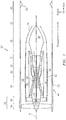
- FIG. 1 schematically illustrates an exemplary embodiment of a gas turbine engine 20.
- the gas turbine engine 20 may be an adaptive cycle two-spool bypass turbofan that may include: a fan section 22 with a first fan section 24 and a second fan section 26; a high pressure compressor section 28; a combustor section 30; a high pressure turbine section 32; a low pressure turbine section 34; an exhaust duct section 36; an augmentor section 40 and a nozzle section 42.
- Additional sections, systems and features such as a geared architecture 25 may be located in various engine sections, for example, between the fan sections 24, 26 or aft of the low pressure turbine section 34.
- the sections are defined along a central longitudinal engine axis A about which a low spool 44 and a high spool 46 rotate relative to an engine case structure 48.
- the engine case structure 48 may include an outer case structure 50, an intermediate case structure 52 and an inner case structure 54.
- the inner case structure 54 may be defined as a distinct duct as shown or defined by an outer surface of cases of the high pressure compressor 28, combustor 30, and turbines 32 and 34. It should be appreciated that various integral or assembled structures, may form the case structure 48 to essentially define an exoskeleton that supports the spools 44, 46 for rotation therein.
- a third stream flow path 56 may be defined by the outer case structure 50 and the intermediate case structure 52.
- a second stream flow path 58 may be defined by the intermediate case structure 52 and the inner case structure 54.
- a core flow path 60 may be defined by the inner case structure 54 and/or one or more walls of the high pressure compressor 28 and components (e.g., the combustor 30, the turbines 32 and 34, etc.) downstream/aft of the compressor 28.
- the second stream flow path 58 may be defined radially inward of the third stream flow path 56 and the core flow path 60 may be radially inward of the second stream flow path 58.
- the first fan section 24 may communicate the bypass flow stream into a third stream flow path 56, a second stream flow path 58 and a first or primary core flow path 60 that is in communication with the combustor section 30.
- the second fan section 26 may communicate a second flow stream into the second stream flow path 58 and the core flow path 60.
- the second fan section 26 may be radially inboard and downstream of the first fan section 24 such that some or all flow from the second fan section 26 is communicated into the second stream flow path 58 and the core flow path 60.
- the fan section 22 may alternatively or additionally include other architectures that, for example, include additional or fewer sections each with or without various combinations of adaptive or fixed guide vanes.
- the first fan section 24 and the second fan section 26 may direct airflow into the core flow path 60 such that the core flow stream is further compressed by the high pressure compressor section 28, mixed and burned with fuel in the combustor section 30, then expanded over the turbine sections 32, 34 to rotationally drive the respective high spool 46 and low spool 44 in response to the expansion.
- the core flow path 60 may alternatively or additionally include other architectures that, for example, include additional or fewer sections and or stages each with or without various combinations of variable or fixed guide vanes.
- the exhaust duct section 36 Downstream of the turbine sections 32, 34, the exhaust duct section 36 may be circular in cross-section as typical of an axis-symmetric augmented low bypass turbofan or may include non-axisymmetric cross-section segments. In addition to the various cross-sections, the exhaust duct section 36 may be non-linear with respect to the central longitudinal engine axis A. Furthermore, in addition to the various cross-sections and the various longitudinal shapes, the exhaust duct section 36 may terminate in the nozzle section 42.
- the nozzle section 42 may include a variable flow area exhaust nozzle 62 at the end of the outer case structure 50 that receives flow from the third stream flow path 56, the second stream flow path 58 and the core flow path 60 such as within an embedded engine architecture.
- flow through the third stream flow path 56 may be discharged through a separate, independent nozzle from that is used to discharge flow through the core flow path 60 and the second stream flowpath 58.
- a variable exhaust nozzle 64 at the end of the intermediate case structure 52 that receives the second flow from the second stream flow path 58 and the core flow path 60 may be provided for a podded engine architecture.
- a tailcone 66 may be selectively translated along axis A to further modulate the flow from the second stream flow path 58 and the core flow path 60.
- FIG. 1 represents one possible configuration for an engine 20. Aspects of the disclosure may be applied in connection with other environments, including additional configurations for gas turbine engines. For example, aspects of the disclosure may be applied in connection with non-geared engines.
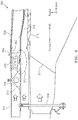
- the engine 200 may correspond to the engine 20 of FIG. 1 .
- the engine 200 is shown with a gas generator/primary flow 'A', a fan discharge bypass flow 'B', and an intermediate fan bypass flow 'C'.
- the primary flow 'A' may correspond to a flow through at least a portion of the core flow path 60 of FIG. 1 .
- the bypass flow 'B' may correspond to a flow through at least a portion of the second stream flow path 58 of FIG. 1 .
- the intermediate fan bypass flow 'C' may correspond to a flow through at least a portion of the third stream flow path 56 of FIG. 1 .
- FIG. 3 A closer view of a portion of the engine 200 denoted by/contained within the dashed circle 202 of FIG. 2 , which portion 202 includes various components of a turbine exhaust section of the engine 200, is shown in FIG. 3 .
- the turbine exhaust section 300 may include various components, such as for example a tierod 304, a turbine exhaust case 310, an augmentor liner 316, an aft inner augmentor duct wall 322, an aft outer augmentor duct wall 328, a fan duct wall 334, a forward augmentor duct wall 340, one or more engine thrust mounts 346, and shear ties 352.
- a flange 362 aft of the engine thrust mount 346 may provide a connection (e.g., a bolted connection) to the aft outer duct wall 328.
- the tierod 304 may be made of one or more materials, such as for example a metal or metal alloy. In some embodiments, the tierod 304 may be formed from nickel or titanium. The tierod 304 may transfer loads from a bearing compartment (not shown), to the forward augmentor duct wall 340. The load may then be transferred from the forward augmentor duct wall 340 to (a truss/flange 344 of the forward augmentor duct wall 340, and then to) the engine thrust mount 346. Alternatively, the tierod 304 may also connect to a duct radially outward from the forward augmentor wall 340 including fan duct wall 334 or adjacent structures. The number/count of tierods 304 that are used may be based on loads that may be present over the operational range of the engine. Between four and sixteen tierods 304 may be used in some embodiments.
- the turbine exhaust case 310 which may be located axially aft of the turbine section of the engine (e.g., turbine section 34 of FIG. 1 ), may be used to contain the gases exhausted by the turbine section (where those gases may be represented by the flow 'A' shown in FIG. 3 ).
- the turbine exhaust case 310 may include one or more aerodynamically-shaped vanes that may facilitate conveying/exhausting the gases.
- the turbine exhaust case 310 may include oil, fuel, or air lines/channels, or combinations thereof, such as for example supply and/or drain lines.
- the augmentor liner 316 may be made of one or more materials, such as for example nickel or cobalt based alloys alloy. In some embodiments, the augmentor liner 316 may be fabricated from non-metallic materials or as a hybrid structure that includes metallic and non-metallic materials. The augmentor liner 316 may be coupled to the turbine exhaust case 310 and may facilitate continued conveyance/exhaustion of the gases.
- the aft inner augmentor duct wall 322 and the aft outer augmentor duct wall 328 each may be made of one or more materials, such as for example nickel or titanium.
- the walls 322 and 328 may be used to contain the flow 'C' shown in FIG. 3 .
- the walls 322 and 328 may provide structural support for an exhaust nozzle/nozzle section (e.g., nozzle section 42 of FIG. 1 ) and may transfer loads from the nozzle section to the engine thrust mount 346. These loads maybe a combination of axial, radial, bending moment and shear loads carried through duct walls 322 and 328.
- the fan duct wall 334 may correspond to the (radially) outermost portion of the engine casing. Fan duct wall 334 may be fabricated from metallic materials (titanium as an example), or from non-metallic materials including organic matrix composites. The fan duct wall 334 may be coupled to the forward augmentor duct wall 340 at the truss/flange 344 of the forward augmentor duct wall 340.
- the forward augmentor duct wall 340 which may be coupled to the tierod 304 as shown, may be used to contain the flow 'C' shown in FIG. 3 .
- the forward augmentor duct wall 340 may be made of one or more materials, such as for example nickel or titanium.
- the engine thrust mount 346 may be made of one or more materials, such as for example titanium or composite.
- the thrust mount 346 may serve as a receptacle for one or more pins and may couple the engine to one or more structures (e.g., a frame of an aircraft).
- the thrust mount 346 may serve as a ground/reference for receiving loads (e.g., thrust loads) of the engine or supporting the engine during assembly and transport.
- the shear ties 352 may be made of one or more materials.
- the shear ties 352 may include sheet metal formed from titanium and nickel based alloys.
- the shear ties 352 may transfer loads (e.g., loads associated with the aft inner augmentor duct wall 322) to the engine thrust mount 346 via the aft outer augmentor duct wall 328.
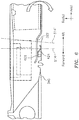
- FIG. 4 A portion of the turbine exhaust section 300 denoted by/contained within the dashed circle 370 of FIG. 3 , which portion 370 includes various components that may be used as a seal assembly/arrangement (between, e.g., the forward augmentor duct wall 340 and the rear inner augmentor duct wall 322) is shown in FIG. 4 .
- assembly of a nozzle module takes place as the assembly is moved, e.g., forward relative to an assembled engine including the fan duct wall 334, truss 344 and engine thrust mount 346 and fastened at the flange 362 described above.
- This assembly may include a seal interface at location 370.
- the assembly 400 may include one or more features, such as for example a ramp/stop 406, a first lead-in section 412, a second lead-in section 418, a finger seal 424, a diaphragm 430, and a sheet extension 436.
- the first lead-in section 412 may be coupled to, or may be included as a portion of, the aft inner augmentor duct wall 322.
- the second lead-in section 418 may be coupled to, or may be included as a portion of, the forward augmentor duct wall 340 (340, or diaphragm 430?).
- the sections 412 and 418 are referred to as "lead-in” sections insofar as during assembly they may represent the portion of their respective duct walls that first come into contact with, or in proximity to, the other of the duct walls. As the perimeter (axisymmetric or asymmetric in shape) of sections 412 and 418 become proximate with relative axial motion during the assembly process, the geometry of the "lead-in” helps to facilitate duct and seal radial positioning.
- the first lead-in section 412 and the second lead-in section 418 may be formed as/include one or more shapes, such as a conical shape.
- the first and second lead-in sections 412/418 may project in both the radial and axial reference directions as shown in FIG. 4 , and may be fully circumferential in order to provide for a conical shape.
- the lead-in sections 412 and 418 assist in nesting during assembly to ensure proper radial orientation of adjacent and overlapping ducts including attached finger seals (e.g., finger seal 424).
- the conical shape of the first lead-in section 412 and the second lead-in section 418 may be used to facilitate installation of the various components shown in FIG. 4 .
- the forward augmentor duct wall 340 may be a (radial) offset between the forward augmentor duct wall 340 and the aft inner augmentor duct wall 322 relative to what is shown in FIG. 4 .
- the conical shape may provide for a self-centering feature by smoothly allowing for an adjustment (e.g., elimination) of that offset.
- the finger seal 424 is installed in a right-to-left/aft-to-forward manner in relation to FIG. 4
- the second lead-in section 418 may help to smoothly guide the finger seal 424 into the position shown in FIG. 4 by incrementally causing the finger seal 424 to compress as it is being positioned.
- the first lead-in section 412 may be located axially forward of the second lead-in section 418 in a final, assembled state. As shown in FIG. 4 , the first lead-in section 412 may be located radially outward/outboard of the second lead-in section 418.
- the finger seal 424 may be disposed between the forward augmentor duct wall 340 and the aft inner augmentor duct wall 322.
- the finger seal 424 may be disposed in a radial gap that is defined/located between the forward augmentor duct wall 340 and the aft inner augmentor duct wall 322.
- the finger seal 424 may be disposed in a region where the forward augmentor duct wall 340 and the aft inner augmentor duct wall 322 axially overlap with one another as shown in FIG. 4 .
- the finger seal 424 may be attached (e.g., riveted) to the aft inner augmentor duct wall 322.
- the finger seal 424 which may be formed from overlapping multi-ply sheet metal segments with ply thickness of, e.g., 0.005 inches to 0.040 inches (approximately 100 micrometers to 1 millimeter), may be used to accommodate nominal/normal deflections between the forward augmentor duct wall 340 and the aft inner augmentor duct wall 322 as described further below.
- the material used in construction of the finger seal 424 is a known art, and may be a metallic alloy (e.g., Inconel 718) with strength adequate to resist permanent plastic deformation during seal compression.
- Each overlapping segment may include features to enable compliance via local deflection of each "finger".
- the finger seal 424 may isolate (e.g., fluidly isolate) the flow 'B' and the flow 'C'.
- the flow 'B' may be at a higher pressure than the flow 'C', such that if the seal 424 was not present there may be a tendency for the flow 'B' to flow into the flowpath associated with the flow 'C'.
- the stop 406 may be coupled to, or included as part of, the aft inner augmentor duct wall 322.
- the stop 406 may be located proximate to the first lead-in section 412.
- the stop 406 may be located aft of the first lead-in section 412.
- the stop 406 may be included/formed using one or more machining operations relative to, e.g., the aft inner augmentor duct wall 322.
- the stop 406 may project from the aft inner augmentor duct wall 322. In some embodiments, the stop 406 may project from the first lead-in section 412. In some embodiments, the stop 406 may project radially outward from duct wall 340. The stop 406 may project axially aft and/or radially inward/inboard relative to the first lead-in section 412.
- the stop 406 may be a full-hoop/full-ring structure.
- the stop 406 may be an interrupted/segmented structure, with each segment consuming a portion of the overall circumference or perimeter of the stop 406.
- the stop 406 may be used as a guide during the construction of the assembly 400. This may be helpful in the event that visibility during construction is impaired or even completely obscured (e.g., where impaired/obscured visibility in this context may be referred to as a so-called "blind assembly procedure").
- the stop 406 may help to maintain shape (e.g., roundness).
- the stop 406 may add stiffness/rigidity to the aft inner augmentor duct wall 322.
- the stop 406, potentially in conjunction with the diaphragm 430, may serve to control (e.g., limit) a deflection (e.g., a radial deflection) of the finger seal 424 as described further below.
- the diaphragm 430 may be coupled to the forward augmentor duct wall 340.
- the diaphragm 430 may be formed integrally with the forward augmentor duct wall 340.
- the diaphragm 430 may be coupled to the forward augmentor duct wall 340 via the sheet extension 436.
- the sheet extension 436 may be riveted or welded to the forward augmentor duct wall 340.
- the sheet extension 436 may be relatively thin; for example, the sheet extension may be approximately 0.040 inches (approximately 1 millimeter) thick in some embodiments.
- the diaphragm 430 may accommodate large deflections (e.g., deflections greater than a threshold) as described further below.
- the diaphragm 430 may include a number of ripples/undulations to facilitate local radial flexure.
- the diaphragm 430 is shown as having two ripples/undulations in FIG. 4 .
- the particular count of ripples/undulations (as well as their dimension [e.g., radial height]) may be a function of the load/deflection that the diaphragm 430 is required to accommodate.
- Diaphragm material e.g. - Inconel 718, may be selected to provide desired deflection under a condition larger than a threshold without permanent or plastic deformation.
- the radial gap between the forward augmentor duct wall 340 and the aft inner augmentor duct wall 322 may change within a (first) range denoted by the arrows 'X' shown in FIG. 5 .
- This change in the radial gap which may be due to relative component deflections (e.g., a deflection of the forward augmentor duct wall 340 relative to the aft inner augmentor duct wall 322 due to imparted loads or relative thermal growth), may be accommodated by the finger seal 424.
- the design of the finger seal 424 may prevent permanent or plastic deformation of the finger seal 424, thereby retaining compliance and sealing effectiveness.
- the axis 514 is superimposed in FIG. 5 .
- the axis 514 may be reflective of the nominal/normal engine operating conditions. The reasons for including the axis 514 will become clearer below in connection with the transient/abnormal engine operating conditions that are described.
- the radial gap between the forward augmentor duct wall 340 and the aft inner augmentor duct wall 322 may close locally to zero at the stop 406 as shown in FIG. 6 .
- the stop 406 may contact the forward augmentor duct wall 340 proximate a radially inner end/surface of the stop 406. Any additional deflection experienced by the engine hardware, e.g., relative deflection between the walls 322 and 340, beyond the range described above in connection with the nominal/normal engine operating conditions may be transferred to the forward augmentor duct wall 340.
- Such a transfer may result in a bending at the location of the diaphragm 430.
- the transfer of the load to the forward augmentor duct wall 340 is reflected by the clockwise skew of the axis 514' in FIG. 6 relative to the axis 514 of FIG. 5 (the axis 514 is carried forward from FIG. 5 to FIG. 6 for ease in comparison between the axis 514' and the axis 514).
- This transfer may reduce the likelihood of, or even prevent, a crushing/deformation of the finger seal 424. In this manner, adequate sealing capability may be maintained during and following the transient/abnormal engine operating conditions.
- whether the engine is operating in a nominal/normal condition or a transient/abnormal condition may be defined by one or more thresholds.
- nominal/normal conditions may be associated with 1 to 5G operations (such as take-off, landing, cruise, etc.).
- transient/abnormal conditions may be associated with 9G operations.
- a given threshold may be based on whether the stop 406 contacts the forward augmentor duct wall 340.
Landscapes
- Engineering & Computer Science (AREA)
- General Engineering & Computer Science (AREA)
- Mechanical Engineering (AREA)
- Chemical & Material Sciences (AREA)
- Combustion & Propulsion (AREA)
- Structures Of Non-Positive Displacement Pumps (AREA)
- Turbine Rotor Nozzle Sealing (AREA)
Applications Claiming Priority (1)
| Application Number | Priority Date | Filing Date | Title |
|---|---|---|---|
| US15/703,164 US10513939B2 (en) | 2017-09-13 | 2017-09-13 | Seal interface with a deflection control feature |
Publications (2)
| Publication Number | Publication Date |
|---|---|
| EP3470632A1 true EP3470632A1 (fr) | 2019-04-17 |
| EP3470632B1 EP3470632B1 (fr) | 2021-11-03 |
Family
ID=62975849
Family Applications (1)
| Application Number | Title | Priority Date | Filing Date |
|---|---|---|---|
| EP18182752.8A Active EP3470632B1 (fr) | 2017-09-13 | 2018-07-10 | Interface de joint avec une caractéristique de commande de déflexion |
Country Status (2)
| Country | Link |
|---|---|
| US (1) | US10513939B2 (fr) |
| EP (1) | EP3470632B1 (fr) |
Families Citing this family (5)
| Publication number | Priority date | Publication date | Assignee | Title |
|---|---|---|---|---|
| US11719191B2 (en) | 2021-06-21 | 2023-08-08 | General Electric Company | Skirted leaf seal apparatus |
| US11674447B2 (en) | 2021-06-29 | 2023-06-13 | General Electric Company | Skirted seal apparatus |
| US11703014B2 (en) | 2021-06-29 | 2023-07-18 | General Electric Company | Flexurally actuated self-sealing plunger apparatus |
| US11692510B2 (en) | 2021-08-20 | 2023-07-04 | General Electric Company | Plunger seal assembly and sealing method |
| US11655722B1 (en) | 2022-01-19 | 2023-05-23 | General Electric Company | Seal assembly and sealing method |
Citations (4)
| Publication number | Priority date | Publication date | Assignee | Title |
|---|---|---|---|---|
| US20050005607A1 (en) * | 2003-05-27 | 2005-01-13 | Snecma Moteurs | System for sealing the secondary flow at the inlet to a nozzle of a turbomachine having a post-combustion chamber |
| US20100301596A1 (en) * | 2007-12-14 | 2010-12-02 | A&S Umwelttechnologie Ag | Coupling for interconnecting at least two pipes |
| US20120104747A1 (en) * | 2010-10-29 | 2012-05-03 | Ruberte Sanchez Jose E | Compliant sealing joint |
| US20150354384A1 (en) | 2012-12-29 | 2015-12-10 | United Technologies Corporation | Bumper for seals in a turbine exhaust case |
Family Cites Families (7)
| Publication number | Priority date | Publication date | Assignee | Title |
|---|---|---|---|---|
| US6079945A (en) | 1997-11-10 | 2000-06-27 | Geneal Electric Company | Brush seal for high-pressure rotor applications |
| US10094285B2 (en) * | 2011-12-08 | 2018-10-09 | Siemens Aktiengesellschaft | Gas turbine outer case active ambient cooling including air exhaust into sub-ambient cavity |
| JP6271582B2 (ja) * | 2012-12-29 | 2018-01-31 | ユナイテッド テクノロジーズ コーポレイションUnited Technologies Corporation | ガスタービンシールアセンブリおよびシール支持体 |
| US9845695B2 (en) * | 2012-12-29 | 2017-12-19 | United Technologies Corporation | Gas turbine seal assembly and seal support |
| US9670791B2 (en) * | 2013-03-04 | 2017-06-06 | United Technologies Corporation | Flexible finger seal for sealing a gap between turbine engine components |
| US10443417B2 (en) * | 2015-09-18 | 2019-10-15 | General Electric Company | Ceramic matrix composite ring shroud retention methods-finger seals with stepped shroud interface |
| US10451084B2 (en) * | 2015-11-16 | 2019-10-22 | General Electric Company | Gas turbine engine with vane having a cooling inlet |
-
2017
- 2017-09-13 US US15/703,164 patent/US10513939B2/en active Active
-
2018
- 2018-07-10 EP EP18182752.8A patent/EP3470632B1/fr active Active
Patent Citations (4)
| Publication number | Priority date | Publication date | Assignee | Title |
|---|---|---|---|---|
| US20050005607A1 (en) * | 2003-05-27 | 2005-01-13 | Snecma Moteurs | System for sealing the secondary flow at the inlet to a nozzle of a turbomachine having a post-combustion chamber |
| US20100301596A1 (en) * | 2007-12-14 | 2010-12-02 | A&S Umwelttechnologie Ag | Coupling for interconnecting at least two pipes |
| US20120104747A1 (en) * | 2010-10-29 | 2012-05-03 | Ruberte Sanchez Jose E | Compliant sealing joint |
| US20150354384A1 (en) | 2012-12-29 | 2015-12-10 | United Technologies Corporation | Bumper for seals in a turbine exhaust case |
Also Published As
| Publication number | Publication date |
|---|---|
| US20190078453A1 (en) | 2019-03-14 |
| US10513939B2 (en) | 2019-12-24 |
| EP3470632B1 (fr) | 2021-11-03 |
Similar Documents
| Publication | Publication Date | Title |
|---|---|---|
| EP3470632B1 (fr) | Interface de joint avec une caractéristique de commande de déflexion | |
| EP2710228B1 (fr) | Carénage d'une structure de turbine à gaz | |
| EP3779131B1 (fr) | Agencement de composant de passage d'écoulement et section de turbine associée pour un moteur à turbine à gaz | |
| EP2163748B1 (fr) | Carter d'admission et de soufflante intégré | |
| EP1947298B1 (fr) | Ensemble de joint coulissant pour moteur de turbine à gaz | |
| EP3102810B1 (fr) | Joint d'étanchéité axial périphérique pour auge segmenté d'une turbine à gaz | |
| EP3012494B1 (fr) | Joint coulissant | |
| EP3219924B1 (fr) | Joint d'air extérieur d'aube de moteur à turbine avec plaque de couverture de transmission de charge | |
| EP3219934B1 (fr) | Ensemble d'étanchéité pour moteur de turbine à gaz | |
| US10851734B2 (en) | Thrust reverser assembly | |
| US9835043B2 (en) | Guided binding-resistant actuation apparatus and method | |
| EP0623742A1 (fr) | Dispositif d'étanchéité pour tuyère avec plaque de base amovible | |
| US20130092756A1 (en) | Variable area nozzle for gas turbine engine | |
| EP3441601B1 (fr) | Butée d'inverseur de poussée de moteur à turbine | |
| EP3030753B1 (fr) | Géométrie de plaque de joint d'étanchéité arrière de moteur à turbine à gaz | |
| US20180179959A1 (en) | Duct blocker seal assembly for a gas turbine engine | |
| EP2813762B1 (fr) | Équipement de combustion | |
| EP2735708B1 (fr) | Agencement d'étanchéité de moteur d'avion | |
| EP2636852B1 (fr) | Joint d'air interne hybride pour moteurs à turbine à gaz | |
| EP3358149B1 (fr) | Soupape de purge sollicitée vers une position neutrale ou fermée | |
| EP3336318B1 (fr) | Entretoises de cadres d'échappement de systèmes de turbine | |
| EP3282101B1 (fr) | Cale pour moteur de turbine à gaz | |
| EP2594752B1 (fr) | Segment de revêtement d'échappement rétractable pour moteurs à turbine à gaz | |
| EP2905427B1 (fr) | Agencement d'étanchéité de moteur à turbine à gaz | |
| US20220074315A1 (en) | Turbine engine with a shroud assembly |
Legal Events
| Date | Code | Title | Description |
|---|---|---|---|
| PUAI | Public reference made under article 153(3) epc to a published international application that has entered the european phase |
Free format text: ORIGINAL CODE: 0009012 |
|
| STAA | Information on the status of an ep patent application or granted ep patent |
Free format text: STATUS: THE APPLICATION HAS BEEN PUBLISHED |
|
| AK | Designated contracting states |
Kind code of ref document: A1 Designated state(s): AL AT BE BG CH CY CZ DE DK EE ES FI FR GB GR HR HU IE IS IT LI LT LU LV MC MK MT NL NO PL PT RO RS SE SI SK SM TR |
|
| AX | Request for extension of the european patent |
Extension state: BA ME |
|
| STAA | Information on the status of an ep patent application or granted ep patent |
Free format text: STATUS: REQUEST FOR EXAMINATION WAS MADE |
|
| 17P | Request for examination filed |
Effective date: 20191017 |
|
| RBV | Designated contracting states (corrected) |
Designated state(s): AL AT BE BG CH CY CZ DE DK EE ES FI FR GB GR HR HU IE IS IT LI LT LU LV MC MK MT NL NO PL PT RO RS SE SI SK SM TR |
|
| STAA | Information on the status of an ep patent application or granted ep patent |
Free format text: STATUS: EXAMINATION IS IN PROGRESS |
|
| 17Q | First examination report despatched |
Effective date: 20191210 |
|
| STAA | Information on the status of an ep patent application or granted ep patent |
Free format text: STATUS: EXAMINATION IS IN PROGRESS |
|
| RAP1 | Party data changed (applicant data changed or rights of an application transferred) |
Owner name: RAYTHEON TECHNOLOGIES CORPORATION |
|
| REG | Reference to a national code |
Ref country code: DE Ref legal event code: R079 Ref document number: 602018025976 Country of ref document: DE Free format text: PREVIOUS MAIN CLASS: F01D0011000000 Ipc: F02K0001800000 |
|
| GRAP | Despatch of communication of intention to grant a patent |
Free format text: ORIGINAL CODE: EPIDOSNIGR1 |
|
| STAA | Information on the status of an ep patent application or granted ep patent |
Free format text: STATUS: GRANT OF PATENT IS INTENDED |
|
| RIC1 | Information provided on ipc code assigned before grant |
Ipc: F02K 3/077 20060101ALI20210427BHEP Ipc: F02K 1/80 20060101AFI20210427BHEP |
|
| INTG | Intention to grant announced |
Effective date: 20210527 |
|
| GRAS | Grant fee paid |
Free format text: ORIGINAL CODE: EPIDOSNIGR3 |
|
| GRAA | (expected) grant |
Free format text: ORIGINAL CODE: 0009210 |
|
| STAA | Information on the status of an ep patent application or granted ep patent |
Free format text: STATUS: THE PATENT HAS BEEN GRANTED |
|
| AK | Designated contracting states |
Kind code of ref document: B1 Designated state(s): AL AT BE BG CH CY CZ DE DK EE ES FI FR GB GR HR HU IE IS IT LI LT LU LV MC MK MT NL NO PL PT RO RS SE SI SK SM TR |
|
| REG | Reference to a national code |
Ref country code: GB Ref legal event code: FG4D |
|
| REG | Reference to a national code |
Ref country code: AT Ref legal event code: REF Ref document number: 1444151 Country of ref document: AT Kind code of ref document: T Effective date: 20211115 Ref country code: CH Ref legal event code: EP |
|
| REG | Reference to a national code |
Ref country code: IE Ref legal event code: FG4D |
|
| REG | Reference to a national code |
Ref country code: DE Ref legal event code: R096 Ref document number: 602018025976 Country of ref document: DE |
|
| REG | Reference to a national code |
Ref country code: LT Ref legal event code: MG9D |
|
| REG | Reference to a national code |
Ref country code: NL Ref legal event code: MP Effective date: 20211103 |
|
| REG | Reference to a national code |
Ref country code: AT Ref legal event code: MK05 Ref document number: 1444151 Country of ref document: AT Kind code of ref document: T Effective date: 20211103 |
|
| PG25 | Lapsed in a contracting state [announced via postgrant information from national office to epo] |
Ref country code: RS Free format text: LAPSE BECAUSE OF FAILURE TO SUBMIT A TRANSLATION OF THE DESCRIPTION OR TO PAY THE FEE WITHIN THE PRESCRIBED TIME-LIMIT Effective date: 20211103 Ref country code: LT Free format text: LAPSE BECAUSE OF FAILURE TO SUBMIT A TRANSLATION OF THE DESCRIPTION OR TO PAY THE FEE WITHIN THE PRESCRIBED TIME-LIMIT Effective date: 20211103 Ref country code: FI Free format text: LAPSE BECAUSE OF FAILURE TO SUBMIT A TRANSLATION OF THE DESCRIPTION OR TO PAY THE FEE WITHIN THE PRESCRIBED TIME-LIMIT Effective date: 20211103 Ref country code: BG Free format text: LAPSE BECAUSE OF FAILURE TO SUBMIT A TRANSLATION OF THE DESCRIPTION OR TO PAY THE FEE WITHIN THE PRESCRIBED TIME-LIMIT Effective date: 20220203 Ref country code: AT Free format text: LAPSE BECAUSE OF FAILURE TO SUBMIT A TRANSLATION OF THE DESCRIPTION OR TO PAY THE FEE WITHIN THE PRESCRIBED TIME-LIMIT Effective date: 20211103 |
|
| PG25 | Lapsed in a contracting state [announced via postgrant information from national office to epo] |
Ref country code: IS Free format text: LAPSE BECAUSE OF FAILURE TO SUBMIT A TRANSLATION OF THE DESCRIPTION OR TO PAY THE FEE WITHIN THE PRESCRIBED TIME-LIMIT Effective date: 20220303 Ref country code: SE Free format text: LAPSE BECAUSE OF FAILURE TO SUBMIT A TRANSLATION OF THE DESCRIPTION OR TO PAY THE FEE WITHIN THE PRESCRIBED TIME-LIMIT Effective date: 20211103 Ref country code: PT Free format text: LAPSE BECAUSE OF FAILURE TO SUBMIT A TRANSLATION OF THE DESCRIPTION OR TO PAY THE FEE WITHIN THE PRESCRIBED TIME-LIMIT Effective date: 20220303 Ref country code: PL Free format text: LAPSE BECAUSE OF FAILURE TO SUBMIT A TRANSLATION OF THE DESCRIPTION OR TO PAY THE FEE WITHIN THE PRESCRIBED TIME-LIMIT Effective date: 20211103 Ref country code: NO Free format text: LAPSE BECAUSE OF FAILURE TO SUBMIT A TRANSLATION OF THE DESCRIPTION OR TO PAY THE FEE WITHIN THE PRESCRIBED TIME-LIMIT Effective date: 20220203 Ref country code: NL Free format text: LAPSE BECAUSE OF FAILURE TO SUBMIT A TRANSLATION OF THE DESCRIPTION OR TO PAY THE FEE WITHIN THE PRESCRIBED TIME-LIMIT Effective date: 20211103 Ref country code: LV Free format text: LAPSE BECAUSE OF FAILURE TO SUBMIT A TRANSLATION OF THE DESCRIPTION OR TO PAY THE FEE WITHIN THE PRESCRIBED TIME-LIMIT Effective date: 20211103 Ref country code: HR Free format text: LAPSE BECAUSE OF FAILURE TO SUBMIT A TRANSLATION OF THE DESCRIPTION OR TO PAY THE FEE WITHIN THE PRESCRIBED TIME-LIMIT Effective date: 20211103 Ref country code: GR Free format text: LAPSE BECAUSE OF FAILURE TO SUBMIT A TRANSLATION OF THE DESCRIPTION OR TO PAY THE FEE WITHIN THE PRESCRIBED TIME-LIMIT Effective date: 20220204 Ref country code: ES Free format text: LAPSE BECAUSE OF FAILURE TO SUBMIT A TRANSLATION OF THE DESCRIPTION OR TO PAY THE FEE WITHIN THE PRESCRIBED TIME-LIMIT Effective date: 20211103 |
|
| PG25 | Lapsed in a contracting state [announced via postgrant information from national office to epo] |
Ref country code: SM Free format text: LAPSE BECAUSE OF FAILURE TO SUBMIT A TRANSLATION OF THE DESCRIPTION OR TO PAY THE FEE WITHIN THE PRESCRIBED TIME-LIMIT Effective date: 20211103 Ref country code: SK Free format text: LAPSE BECAUSE OF FAILURE TO SUBMIT A TRANSLATION OF THE DESCRIPTION OR TO PAY THE FEE WITHIN THE PRESCRIBED TIME-LIMIT Effective date: 20211103 Ref country code: RO Free format text: LAPSE BECAUSE OF FAILURE TO SUBMIT A TRANSLATION OF THE DESCRIPTION OR TO PAY THE FEE WITHIN THE PRESCRIBED TIME-LIMIT Effective date: 20211103 Ref country code: EE Free format text: LAPSE BECAUSE OF FAILURE TO SUBMIT A TRANSLATION OF THE DESCRIPTION OR TO PAY THE FEE WITHIN THE PRESCRIBED TIME-LIMIT Effective date: 20211103 Ref country code: DK Free format text: LAPSE BECAUSE OF FAILURE TO SUBMIT A TRANSLATION OF THE DESCRIPTION OR TO PAY THE FEE WITHIN THE PRESCRIBED TIME-LIMIT Effective date: 20211103 Ref country code: CZ Free format text: LAPSE BECAUSE OF FAILURE TO SUBMIT A TRANSLATION OF THE DESCRIPTION OR TO PAY THE FEE WITHIN THE PRESCRIBED TIME-LIMIT Effective date: 20211103 |
|
| REG | Reference to a national code |
Ref country code: DE Ref legal event code: R097 Ref document number: 602018025976 Country of ref document: DE |
|
| PLBE | No opposition filed within time limit |
Free format text: ORIGINAL CODE: 0009261 |
|
| STAA | Information on the status of an ep patent application or granted ep patent |
Free format text: STATUS: NO OPPOSITION FILED WITHIN TIME LIMIT |
|
| 26N | No opposition filed |
Effective date: 20220804 |
|
| PG25 | Lapsed in a contracting state [announced via postgrant information from national office to epo] |
Ref country code: AL Free format text: LAPSE BECAUSE OF FAILURE TO SUBMIT A TRANSLATION OF THE DESCRIPTION OR TO PAY THE FEE WITHIN THE PRESCRIBED TIME-LIMIT Effective date: 20211103 |
|
| PG25 | Lapsed in a contracting state [announced via postgrant information from national office to epo] |
Ref country code: SI Free format text: LAPSE BECAUSE OF FAILURE TO SUBMIT A TRANSLATION OF THE DESCRIPTION OR TO PAY THE FEE WITHIN THE PRESCRIBED TIME-LIMIT Effective date: 20211103 |
|
| PG25 | Lapsed in a contracting state [announced via postgrant information from national office to epo] |
Ref country code: MC Free format text: LAPSE BECAUSE OF FAILURE TO SUBMIT A TRANSLATION OF THE DESCRIPTION OR TO PAY THE FEE WITHIN THE PRESCRIBED TIME-LIMIT Effective date: 20211103 |
|
| REG | Reference to a national code |
Ref country code: CH Ref legal event code: PL |
|
| REG | Reference to a national code |
Ref country code: BE Ref legal event code: MM Effective date: 20220731 |
|
| PG25 | Lapsed in a contracting state [announced via postgrant information from national office to epo] |
Ref country code: LU Free format text: LAPSE BECAUSE OF NON-PAYMENT OF DUE FEES Effective date: 20220710 Ref country code: LI Free format text: LAPSE BECAUSE OF NON-PAYMENT OF DUE FEES Effective date: 20220731 Ref country code: CH Free format text: LAPSE BECAUSE OF NON-PAYMENT OF DUE FEES Effective date: 20220731 |
|
| PG25 | Lapsed in a contracting state [announced via postgrant information from national office to epo] |
Ref country code: IT Free format text: LAPSE BECAUSE OF FAILURE TO SUBMIT A TRANSLATION OF THE DESCRIPTION OR TO PAY THE FEE WITHIN THE PRESCRIBED TIME-LIMIT Effective date: 20211103 Ref country code: BE Free format text: LAPSE BECAUSE OF NON-PAYMENT OF DUE FEES Effective date: 20220731 |
|
| P01 | Opt-out of the competence of the unified patent court (upc) registered |
Effective date: 20230521 |
|
| PG25 | Lapsed in a contracting state [announced via postgrant information from national office to epo] |
Ref country code: IE Free format text: LAPSE BECAUSE OF NON-PAYMENT OF DUE FEES Effective date: 20220710 |
|
| PGFP | Annual fee paid to national office [announced via postgrant information from national office to epo] |
Ref country code: DE Payment date: 20230620 Year of fee payment: 6 |
|
| PG25 | Lapsed in a contracting state [announced via postgrant information from national office to epo] |
Ref country code: HU Free format text: LAPSE BECAUSE OF FAILURE TO SUBMIT A TRANSLATION OF THE DESCRIPTION OR TO PAY THE FEE WITHIN THE PRESCRIBED TIME-LIMIT; INVALID AB INITIO Effective date: 20180710 |
|
| PG25 | Lapsed in a contracting state [announced via postgrant information from national office to epo] |
Ref country code: MK Free format text: LAPSE BECAUSE OF FAILURE TO SUBMIT A TRANSLATION OF THE DESCRIPTION OR TO PAY THE FEE WITHIN THE PRESCRIBED TIME-LIMIT Effective date: 20211103 Ref country code: CY Free format text: LAPSE BECAUSE OF FAILURE TO SUBMIT A TRANSLATION OF THE DESCRIPTION OR TO PAY THE FEE WITHIN THE PRESCRIBED TIME-LIMIT Effective date: 20211103 |
|
| PG25 | Lapsed in a contracting state [announced via postgrant information from national office to epo] |
Ref country code: TR Free format text: LAPSE BECAUSE OF FAILURE TO SUBMIT A TRANSLATION OF THE DESCRIPTION OR TO PAY THE FEE WITHIN THE PRESCRIBED TIME-LIMIT Effective date: 20211103 |
|
| PGFP | Annual fee paid to national office [announced via postgrant information from national office to epo] |
Ref country code: GB Payment date: 20240620 Year of fee payment: 7 |
|
| PGFP | Annual fee paid to national office [announced via postgrant information from national office to epo] |
Ref country code: FR Payment date: 20240619 Year of fee payment: 7 |