EP3470629B1 - Film cooling hole arrangement for gas turbine engine component - Google Patents
Film cooling hole arrangement for gas turbine engine component Download PDFInfo
- Publication number
- EP3470629B1 EP3470629B1 EP18200554.6A EP18200554A EP3470629B1 EP 3470629 B1 EP3470629 B1 EP 3470629B1 EP 18200554 A EP18200554 A EP 18200554A EP 3470629 B1 EP3470629 B1 EP 3470629B1
- Authority
- EP
- European Patent Office
- Prior art keywords
- protrusion
- cooling
- component
- protrusions
- gas turbine
- Prior art date
- Legal status (The legal status is an assumption and is not a legal conclusion. Google has not performed a legal analysis and makes no representation as to the accuracy of the status listed.)
- Active
Links
- 238000001816 cooling Methods 0.000 title claims description 81
- 238000005266 casting Methods 0.000 claims description 8
- 238000004891 communication Methods 0.000 claims description 2
- NJPPVKZQTLUDBO-UHFFFAOYSA-N novaluron Chemical compound C1=C(Cl)C(OC(F)(F)C(OC(F)(F)F)F)=CC=C1NC(=O)NC(=O)C1=C(F)C=CC=C1F NJPPVKZQTLUDBO-UHFFFAOYSA-N 0.000 description 8
- 238000012546 transfer Methods 0.000 description 6
- 239000000446 fuel Substances 0.000 description 5
- 230000009467 reduction Effects 0.000 description 4
- 238000000926 separation method Methods 0.000 description 4
- 238000000034 method Methods 0.000 description 3
- 230000003068 static effect Effects 0.000 description 3
- 239000000463 material Substances 0.000 description 2
- 230000008569 process Effects 0.000 description 2
- 230000003416 augmentation Effects 0.000 description 1
- 230000003190 augmentative effect Effects 0.000 description 1
- 230000015572 biosynthetic process Effects 0.000 description 1
- 230000008859 change Effects 0.000 description 1
- 230000006835 compression Effects 0.000 description 1
- 238000007906 compression Methods 0.000 description 1
- 230000003750 conditioning effect Effects 0.000 description 1
- 239000012809 cooling fluid Substances 0.000 description 1
- 238000012937 correction Methods 0.000 description 1
- 238000005553 drilling Methods 0.000 description 1
- 230000000694 effects Effects 0.000 description 1
- 238000004519 manufacturing process Methods 0.000 description 1
- 230000007246 mechanism Effects 0.000 description 1
- 238000012986 modification Methods 0.000 description 1
- 230000004048 modification Effects 0.000 description 1
- 230000037361 pathway Effects 0.000 description 1
- 230000004044 response Effects 0.000 description 1
- 238000011144 upstream manufacturing Methods 0.000 description 1
Images


Classifications
-
- F—MECHANICAL ENGINEERING; LIGHTING; HEATING; WEAPONS; BLASTING
- F01—MACHINES OR ENGINES IN GENERAL; ENGINE PLANTS IN GENERAL; STEAM ENGINES
- F01D—NON-POSITIVE DISPLACEMENT MACHINES OR ENGINES, e.g. STEAM TURBINES
- F01D5/00—Blades; Blade-carrying members; Heating, heat-insulating, cooling or antivibration means on the blades or the members
- F01D5/12—Blades
- F01D5/14—Form or construction
- F01D5/18—Hollow blades, i.e. blades with cooling or heating channels or cavities; Heating, heat-insulating or cooling means on blades
- F01D5/186—Film cooling
-
- F—MECHANICAL ENGINEERING; LIGHTING; HEATING; WEAPONS; BLASTING
- F01—MACHINES OR ENGINES IN GENERAL; ENGINE PLANTS IN GENERAL; STEAM ENGINES
- F01D—NON-POSITIVE DISPLACEMENT MACHINES OR ENGINES, e.g. STEAM TURBINES
- F01D25/00—Component parts, details, or accessories, not provided for in, or of interest apart from, other groups
- F01D25/08—Cooling; Heating; Heat-insulation
- F01D25/12—Cooling
-
- F—MECHANICAL ENGINEERING; LIGHTING; HEATING; WEAPONS; BLASTING
- F01—MACHINES OR ENGINES IN GENERAL; ENGINE PLANTS IN GENERAL; STEAM ENGINES
- F01D—NON-POSITIVE DISPLACEMENT MACHINES OR ENGINES, e.g. STEAM TURBINES
- F01D5/00—Blades; Blade-carrying members; Heating, heat-insulating, cooling or antivibration means on the blades or the members
- F01D5/12—Blades
- F01D5/14—Form or construction
- F01D5/18—Hollow blades, i.e. blades with cooling or heating channels or cavities; Heating, heat-insulating or cooling means on blades
- F01D5/187—Convection cooling
-
- F—MECHANICAL ENGINEERING; LIGHTING; HEATING; WEAPONS; BLASTING
- F01—MACHINES OR ENGINES IN GENERAL; ENGINE PLANTS IN GENERAL; STEAM ENGINES
- F01D—NON-POSITIVE DISPLACEMENT MACHINES OR ENGINES, e.g. STEAM TURBINES
- F01D9/00—Stators
- F01D9/02—Nozzles; Nozzle boxes; Stator blades; Guide conduits, e.g. individual nozzles
- F01D9/04—Nozzles; Nozzle boxes; Stator blades; Guide conduits, e.g. individual nozzles forming ring or sector
- F01D9/041—Nozzles; Nozzle boxes; Stator blades; Guide conduits, e.g. individual nozzles forming ring or sector using blades
-
- F—MECHANICAL ENGINEERING; LIGHTING; HEATING; WEAPONS; BLASTING
- F01—MACHINES OR ENGINES IN GENERAL; ENGINE PLANTS IN GENERAL; STEAM ENGINES
- F01D—NON-POSITIVE DISPLACEMENT MACHINES OR ENGINES, e.g. STEAM TURBINES
- F01D9/00—Stators
- F01D9/06—Fluid supply conduits to nozzles or the like
- F01D9/065—Fluid supply or removal conduits traversing the working fluid flow, e.g. for lubrication-, cooling-, or sealing fluids
-
- F—MECHANICAL ENGINEERING; LIGHTING; HEATING; WEAPONS; BLASTING
- F05—INDEXING SCHEMES RELATING TO ENGINES OR PUMPS IN VARIOUS SUBCLASSES OF CLASSES F01-F04
- F05D—INDEXING SCHEME FOR ASPECTS RELATING TO NON-POSITIVE-DISPLACEMENT MACHINES OR ENGINES, GAS-TURBINES OR JET-PROPULSION PLANTS
- F05D2220/00—Application
- F05D2220/30—Application in turbines
- F05D2220/32—Application in turbines in gas turbines
-
- F—MECHANICAL ENGINEERING; LIGHTING; HEATING; WEAPONS; BLASTING
- F05—INDEXING SCHEMES RELATING TO ENGINES OR PUMPS IN VARIOUS SUBCLASSES OF CLASSES F01-F04
- F05D—INDEXING SCHEME FOR ASPECTS RELATING TO NON-POSITIVE-DISPLACEMENT MACHINES OR ENGINES, GAS-TURBINES OR JET-PROPULSION PLANTS
- F05D2230/00—Manufacture
- F05D2230/20—Manufacture essentially without removing material
- F05D2230/21—Manufacture essentially without removing material by casting
-
- F—MECHANICAL ENGINEERING; LIGHTING; HEATING; WEAPONS; BLASTING
- F05—INDEXING SCHEMES RELATING TO ENGINES OR PUMPS IN VARIOUS SUBCLASSES OF CLASSES F01-F04
- F05D—INDEXING SCHEME FOR ASPECTS RELATING TO NON-POSITIVE-DISPLACEMENT MACHINES OR ENGINES, GAS-TURBINES OR JET-PROPULSION PLANTS
- F05D2240/00—Components
- F05D2240/10—Stators
- F05D2240/11—Shroud seal segments
-
- F—MECHANICAL ENGINEERING; LIGHTING; HEATING; WEAPONS; BLASTING
- F05—INDEXING SCHEMES RELATING TO ENGINES OR PUMPS IN VARIOUS SUBCLASSES OF CLASSES F01-F04
- F05D—INDEXING SCHEME FOR ASPECTS RELATING TO NON-POSITIVE-DISPLACEMENT MACHINES OR ENGINES, GAS-TURBINES OR JET-PROPULSION PLANTS
- F05D2250/00—Geometry
- F05D2250/70—Shape
- F05D2250/75—Shape given by its similarity to a letter, e.g. T-shaped
-
- F—MECHANICAL ENGINEERING; LIGHTING; HEATING; WEAPONS; BLASTING
- F05—INDEXING SCHEMES RELATING TO ENGINES OR PUMPS IN VARIOUS SUBCLASSES OF CLASSES F01-F04
- F05D—INDEXING SCHEME FOR ASPECTS RELATING TO NON-POSITIVE-DISPLACEMENT MACHINES OR ENGINES, GAS-TURBINES OR JET-PROPULSION PLANTS
- F05D2260/00—Function
- F05D2260/20—Heat transfer, e.g. cooling
- F05D2260/201—Heat transfer, e.g. cooling by impingement of a fluid
-
- F—MECHANICAL ENGINEERING; LIGHTING; HEATING; WEAPONS; BLASTING
- F05—INDEXING SCHEMES RELATING TO ENGINES OR PUMPS IN VARIOUS SUBCLASSES OF CLASSES F01-F04
- F05D—INDEXING SCHEME FOR ASPECTS RELATING TO NON-POSITIVE-DISPLACEMENT MACHINES OR ENGINES, GAS-TURBINES OR JET-PROPULSION PLANTS
- F05D2260/00—Function
- F05D2260/20—Heat transfer, e.g. cooling
- F05D2260/202—Heat transfer, e.g. cooling by film cooling
-
- F—MECHANICAL ENGINEERING; LIGHTING; HEATING; WEAPONS; BLASTING
- F05—INDEXING SCHEMES RELATING TO ENGINES OR PUMPS IN VARIOUS SUBCLASSES OF CLASSES F01-F04
- F05D—INDEXING SCHEME FOR ASPECTS RELATING TO NON-POSITIVE-DISPLACEMENT MACHINES OR ENGINES, GAS-TURBINES OR JET-PROPULSION PLANTS
- F05D2260/00—Function
- F05D2260/20—Heat transfer, e.g. cooling
- F05D2260/221—Improvement of heat transfer
- F05D2260/2212—Improvement of heat transfer by creating turbulence
-
- F—MECHANICAL ENGINEERING; LIGHTING; HEATING; WEAPONS; BLASTING
- F05—INDEXING SCHEMES RELATING TO ENGINES OR PUMPS IN VARIOUS SUBCLASSES OF CLASSES F01-F04
- F05D—INDEXING SCHEME FOR ASPECTS RELATING TO NON-POSITIVE-DISPLACEMENT MACHINES OR ENGINES, GAS-TURBINES OR JET-PROPULSION PLANTS
- F05D2260/00—Function
- F05D2260/20—Heat transfer, e.g. cooling
- F05D2260/221—Improvement of heat transfer
- F05D2260/2214—Improvement of heat transfer by increasing the heat transfer surface
- F05D2260/22141—Improvement of heat transfer by increasing the heat transfer surface using fins or ribs
Description
- Exemplary embodiments pertain to the art of gas turbine engines, and more particularly to cooling of gas turbine engine components.
- Gas turbines hot section components, for example, turbine vanes and blades and blade outer air seals, in the turbine section of the gas turbine engine are configured for use within particular temperature ranges. Often, the conditions in which the components are operated exceed a maximum useful temperature of the material of which the components are formed. Thus, such components often rely on cooling airflow to cool the components during operation. For example, stationary turbine vanes often have internal passages for cooling airflow to flow through, and additionally may have openings in an outer surface of the vane for cooling airflow to exit the interior of the vane structure and form a cooling film of air over the outer surface to provide the necessary thermal conditioning. Similar internal cooling passages are often included in other components, such as the aforementioned turbine blades and blade outer air seals.
- Internal features such as pedestals and/or pin fins are often included in the cooling passages, affixed to one or more walls of the cooling passage to increase turbulence of the cooling airflow flowing through the cooling passage, thereby improving heat transfer characteristics of the cooling passage. Currently there is a limit for the spacing of the pedestals and pin fins for adjacent rows. This is because for each feature such as a pedestal or pin fin a separation bubble forms on the downstream side of the feature. If the spacing is too close the separation bubble does not close before hitting the next pedestal or pin fin row. This reduces the heat transfer augmentation of the internal features because the strength of the secondary flows formed on the adjacent pedestal or pin fin row (horseshoe vortex) and the velocity coming into the adjacent row is significantly dropped. Again this drastically reduces the effectiveness of the pedestals and/or pin fins, reducing thermal energy transfer from the component to the airflow.
-
US 2015/0016947 A1 discloses an augmented cooling system using inner and outer trip strips to deflect a cooling fluid transversing a cooling pathway. -
US 2006/0210399 A1 discloses a turbine blade with a cooling passageway containing cylindrical protrusions to generate turbulent flow. -
EP 3179041 A1 discloses an engine component comprising a wall having a plurality of film holes and at least one turbulator to provide a steady flow of cooling to the film hole. -
JP H11 257005 A - According to the present invention, there is provided a component for a gas turbine engine with the features of claim 1, the component comprising: an outer surface bounding a hot gas path of the gas turbine engine; a cooling passage configured to deliver a cooling airflow therethrough, including: a passage wall located opposite the outer surface to define a component thickness; and a plurality of protrusions arranged in a plurality of protrusion rows and located along the passage wall, each protrusion having a protrusion height extending from the passage wall and a protrusion streamwise width extending along the passage wall in a flow direction of the cooling airflow through the cooling passage; and a plurality of cooling holes extending from the passage wall to the outer surface, each cooling hole of the plurality of cooling holes having a cooling hole inlet at the passage wall located in a protrusion wake region downstream of an associated protrusion of the plurality of protrusions; wherein a ratio of protrusion streamwise spacing to protrusion diameter is 2.5 or less.
- The ratio of protrusion streamwise spacing to protrusion diameter may be 2.0 or less.
- The cooling hole inlet may be located downstream of a protrusion of the plurality of protrusions between 0 and 1.5 protrusion diameters from the protrusion.
- A protrusion of the plurality of protrusions may have a circular cross-section.
- The one or more cooling holes may be configured to divert a portion of the cooling airflow therethrough, to form a cooling film at the outer surface.
- The plurality of protrusions may include one or more pedestals and/or one or more pin fins.
- The component may be formed via casting.
- The plurality of protrusions and the plurality of cooling film holes may be formed via a common casting tool.
- The following descriptions should not be considered limiting in any way. With reference to the accompanying drawings, like elements are numbered alike:
-
FIG. 1 is a cross-sectional view of an embodiment of a gas turbine engine; -
FIG. 2 is a partial cross-sectional view of an embodiment of a turbine section of a gas turbine engine; -
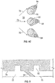
FIG. 3A is a partial cross-sectional view of an embodiment of a gas turbine engine component including one or more pedestals; -
FIG. 3B is a partial cross-sectional view of an embodiment of a gas turbine engine component including one or more pin fins; -
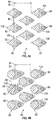
FIG. 4A is a plan view of a pedestal or pin fin arrangement for an embodiment of a gas turbine engine component; -
FIG. 4B is a plan view of another pedestal or pin fin arrangement for an embodiment of a gas turbine engine component; -
FIG. 4C is a plan view of another pedestal or pin fin arrangement for an embodiment of a gas turbine engine component; and -
FIG. 5 is a schematic view of a portion of a manufacturing method of a turbine vane. - A detailed description of one or more embodiments of the disclosed apparatus and method are presented herein by way of exemplification and not limitation with reference to the Figures.
-
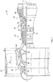
FIG. 1 schematically illustrates agas turbine engine 20. Thegas turbine engine 20 is disclosed herein as a two-spool turbofan that generally incorporates afan section 22, acompressor section 24, acombustor section 26 and aturbine section 28. Alternative engines might include an augmentor section (not shown) among other systems or features. Thefan section 22 drives air along a bypass flow path B in a bypass duct, while thecompressor section 24 drives air along a core flow path C for compression and communication into thecombustor section 26 then expansion through theturbine section 28. Although depicted as a two-spool turbofan gas turbine engine in the disclosed non-limiting embodiment, it should be understood that the concepts described herein are not limited to use with two-spool turbofans as the teachings may be applied to other types of turbine engines including three-spool architectures. - The
exemplary engine 20 generally includes alow speed spool 30 and ahigh speed spool 32 mounted for rotation about an engine central longitudinal axis A relative to an enginestatic structure 36 viaseveral bearing systems 38. It should be understood thatvarious bearing systems 38 at various locations may alternatively or additionally be provided, and the location ofbearing systems 38 may be varied as appropriate to the application. - The
low speed spool 30 generally includes aninner shaft 40 that interconnects afan 42, alow pressure compressor 44 and alow pressure turbine 46. Theinner shaft 40 is connected to thefan 42 through a speed change mechanism, which in exemplarygas turbine engine 20 is illustrated as a gearedarchitecture 48 to drive thefan 42 at a lower speed than thelow speed spool 30. Thehigh speed spool 32 includes anouter shaft 50 that interconnects ahigh pressure compressor 52 andhigh pressure turbine 54. Acombustor 56 is arranged inexemplary gas turbine 20 between thehigh pressure compressor 52 and thehigh pressure turbine 54. An enginestatic structure 36 is arranged generally between thehigh pressure turbine 54 and thelow pressure turbine 46. The enginestatic structure 36 further supports bearingsystems 38 in theturbine section 28. Theinner shaft 40 and theouter shaft 50 are concentric and rotate viabearing systems 38 about the engine central longitudinal axis A which is collinear with their longitudinal axes. - The core airflow is compressed by the
low pressure compressor 44 then thehigh pressure compressor 52, mixed and burned with fuel in thecombustor 56, then expanded over thehigh pressure turbine 54 andlow pressure turbine 46. Theturbines low speed spool 30 andhigh speed spool 32 in response to the expansion. It will be appreciated that each of the positions of thefan section 22,compressor section 24,combustor section 26,turbine section 28, and fandrive gear system 48 may be varied. For example,gear system 48 may be located aft ofcombustor section 26 or even aft ofturbine section 28, andfan section 22 may be positioned forward or aft of the location ofgear system 48. - The
engine 20 in one example is a high-bypass geared aircraft engine. In a further example, theengine 20 bypass ratio is greater than about six (6), with an example embodiment being greater than about ten (10), the gearedarchitecture 48 is an epicyclic gear train, such as a planetary gear system or other gear system, with a gear reduction ratio of greater than about 2.3 and thelow pressure turbine 46 has a pressure ratio that is greater than about five. In one disclosed embodiment, theengine 20 bypass ratio is greater than about ten (10:1), the fan diameter is significantly larger than that of thelow pressure compressor 44, and thelow pressure turbine 46 has a pressure ratio that is greater than about five 5:1.Low pressure turbine 46 pressure ratio is pressure measured prior to inlet oflow pressure turbine 46 as related to the pressure at the outlet of thelow pressure turbine 46 prior to an exhaust nozzle. The gearedarchitecture 48 may be an epicyclic gear train, such as a planetary gear system or other gear system, with a gear reduction ratio of greater than about 2.3:1. It should be understood, however, that the above parameters are only exemplary of one embodiment of a geared architecture engine and that the present disclosure is applicable to other gas turbine engines including direct drive turbofans. - A significant amount of thrust is provided by the bypass flow B due to the high bypass ratio. The
fan section 22 of theengine 20 is designed for a particular flight condition--typically cruise at about 0.8 Mach and about 35,000 feet (10,668 meters). The flight condition of 0.8 Mach and 35,000 ft (10,668 meters), with the engine at its best fuel consumption--also known as "bucket cruise Thrust Specific Fuel Consumption ('TSFC')"--is the industry standard parameter of lbm of fuel being burned divided by lbf of thrust the engine produces at that minimum point. "Low fan pressure ratio" is the pressure ratio across the fan blade alone, without a Fan Exit Guide Vane ("FEGV") system. The low fan pressure ratio as disclosed herein according to one non-limiting embodiment is less than about 1.45. "Low corrected fan tip speed" is the actual fan tip speed in ft/sec divided by an industry standard temperature correction of [(Tram °R)/ (518.7 °R)]0.5. The "Low corrected fan tip speed" as disclosed herein according to one non-limiting embodiment is less than about 1150 ft/second (350.5 m/sec). - Referring now to
FIG. 2 , theturbine section 28 includes one or more sets, or stages of fixedturbine vanes 60 andturbine rotors 62, eachturbine rotor 62 including a plurality ofturbine blades 64. Theturbine blades 64 extend from ablade platform 66 radially outwardly to ablade tip 68. Theblade tip 68 interfaces with a bladeouter airseal 70 to maintain minimal operational clearances and thus operational efficiency of theturbine 28. The turbine vanes 60 and theturbine blades 64 utilize internal cooling passages through which a cooling airflow is circulated to maintain theturbine blades 64 andturbine vanes 60 within a desired temperature range. Similarly, other components such as the bladeouter airseal 70 may utilize similar cooling channels over which cooling airflow is directed to maintain the component at a desired temperature range, to improve the service life of the component. - Referring now to
FIG. 3A, and FIG. 3B shown is a cross-sectional view of anexemplary turbine vane 60. While the description presented herein is in the context of aturbine vane 60, the present disclosure may be readily applied to other components such asturbine blades 64, bladeouter airseals 70, inner and outer end walls, combustor panels, or the like. Theturbine vane 60 includes ahot exterior wall 77 defined between anexternal surface 75 exposed to a hotgas path airflow 89, and aninternal surface 74 defining aninternal cooling passage 72.Cooling airflow 76 flows generally along theinternal cooling passage 72 in a flow direction indicated at 78. A plurality ofinternal protrusions 80, are arrayed along theinternal surface 74. In some embodiments, such as shown inFIG. 3A , theprotrusions 80 are pedestals extending entirely across theinternal cooling passage 72 and thus connected to aninternal surface 74 at each end of the pedestal. In other embodiments, such as shown inFIG. 3B , theinternal protrusions 80 are pin fins extending only partially across theinternal cooling passage 72 and thus are connected to aninternal surface 74 at only one end of the pin fin. - The
internal protrusions 80, whether they are pedestals or pin fins, induce turbulent mixing in thecooling airflow 76 through theinternal cooling passage 72 in order to increase thermal energy transfer between thehot exterior wall 77 and the coolingairflow 76, with theinternal protrusions 80 spaced along theinternal surface 74 to allow for separation and reattachment of a boundary layer of the coolingairflow 76 at theinternal surface 74 for increased thermal energy transfer. - Referring now to
FIG. 4 , in some embodiments, theinternal protrusions 80 are arranged inprotrusion rows 82 having a streamwise protrusion spacing 84 betweenadjacent protrusion rows 82 in a direction parallel to theflow direction 78, measured between closeststreamwise portions 92 of theadjacent protrusion rows 82. Further,adjacent protrusions 80 of thesame protrusion row 82 are arranged having an off-streamwise spacing 86. In some embodiments, such as shown, theprotrusions 80, whether they are pedestals or pin fins, may have a circular cross-section. In other embodiments, theprotrusions 80 may have other cross-sectional shapes, such as oval, elliptical, triangular, or other polygonal shape. In still other embodiments, theprotrusions 80 may have a combination of the above cross-sectional shapes. - Referring again to
FIG. 3A, and FIG. 3B , eachprotrusion 80 has aprotrusion height 88 extending from theinternal surface 74 and aprotrusion streamwise width 90 extending along theinternal surface 74 in theflow direction 78. Further, thehot exterior wall 77 includes a plurality of film cooling holes 94 arrayed along thehot exterior wall 77, and extending therethrough with afilm hole inlet 96 at theinternal surface 74, and afilm hole outlet 98 at anexternal surface 75 of thehot exterior wall 77, opposite theinternal surface 74. In some embodiments thehot exterior wall 77 defines an airfoil portion of theturbine vane 60. The film cooling holes 94 are configured to divert a portion of the coolingairflow 76 from theinternal cooling passage 72 to form a cooling film at theexternal surface 75 to cool thehot exterior wall 77 and protect thehot exterior wall 77 from thehot gaspath airflow 89. - As best shown in
FIG. 4 , film cooling holes 94 are located downstream of eachprotrusion 80, and more specifically thefilm hole inlet 96 is located in aprotrusion wake region 104 downstream of the associatedprotrusion 80. A protrusion to film hole spacing 106 between thefilm hole inlet 96 and theprotrusion 80 is proportional to aprotrusion diameter 108. In some embodiments, the protrusion to film hole spacing 106 is between 0 and 1.5protrusion diameters 108. - The location of the
film hole inlet 96 in thewake region 104, has the effect of sucking a portion of the coolingairflow 76 from theinternal cooling passage 72 to reduce a size of a separation bubble downstream of eachprotrusion 80 leading to improved reattachment of the boundary layer. With improved reattachment of the boundary layer, the spacing of theprotrusions 80 may be reduced. The protrusion streamwise spacing 84 is proportional to theprotrusion diameter 108, and in accordance with the present invention the protrusion streamwise spacing 84 is 2.5protrusion diameters 108 or less. Further, while in some embodiments, thestreamwise flow direction 78 is uniform as shown inFIG. 4 , it is to be appreciated that in some embodiments, as shown inFIG. 4C , theflow direction 78 may locally vary withprotrusion 80 location. Thus, differentfilm cooling hole 94 orientations may be utilized to position each of the film cooling holes 94 is the respective wake of their associated orupstream protrusion 80. - Referring now to
FIG. 5 , the film cooling holes 94 and theadjacent protrusions 80 are formed via casting, in some embodiments via acommon casting core 110. The formation of the features via casting and via acommon casting core 110 provides increased positional accuracy of the features and in a relative position of the film cooling holes 94 and theprotrusions 80 compared to a typical process of forming the film cooling holes via a secondary drilling process. The increased positional accuracy of the placement of theprotrusions 80 and the film cooling holes 94 assures a selected amount of coolingairflow 76 is flowed through the film cooling holes 94, while the streamwise protrusion spacing 84 may be reduced to improve cooling of theturbine vane 60 via thecooling airflow 76 over theprotrusions 80. - The pedestal (pin fin) configurations disclosed herein, with closely-spaced pedestals (pin fins) 80 improves the convective heat transfer and cooling effectiveness of the cooling
airflow 76. Thus, the amount of coolingairflow 76 needed may be reduced without negatively effectingturbine vane 60 service life. The reduction incooling airflow 76 leads to a reduction in thrust-specific fuel consumption (TSFC). - While the present disclosure has been described with reference to an exemplary embodiment or embodiments, it will be understood by those skilled in the art that various changes may be made and equivalents may be substituted for elements thereof without departing from the scope of the present invention, which is defined only by the appended claims. In addition, many modifications may be made to adapt a particular situation or material to the teachings of the present disclosure without departing from the essential scope of the appended claims.
- Therefore, it is intended that the present disclosure not be limited to the particular embodiment disclosed as the best mode contemplated for carrying out this present disclosure, but that the present disclosure will include all embodiments falling within the scope of the claims.
Claims (10)
- A component for a gas turbine engine (20), comprising:an outer surface (75) bounding a hot gas path (89) of the gas turbine engine;a cooling passage (72) configured to deliver a cooling airflow (76) therethrough, including:a passage wall (77) located opposite the outer surface to define a component thickness;a plurality of protrusions (80) arranged in a plurality of protrusion rows (82) and located along the passage wall, each protrusion having a protrusion height (88) extending from the passage wall and a protrusion streamwise width (90) extending along the passage wall in a flow direction (78) of the cooling airflow through the cooling passage; anda plurality of cooling holes (94) extending from the passage wall to the outer surface, characterised in that each cooling hole of the plurality of cooling holes having a cooling hole inlet (96) at the passage wall located in a protrusion wake region (104) downstream of an associated protrusion of the plurality of protrusions;characterised in that a ratio of protrusion streamwise spacing (84) to protrusion diameter (108) is 2.5 or less.
- The component of claim 1, wherein the ratio of protrusion streamwise spacing (84) to protrusion diameter (108) is 2.0 or less.
- The component of any preceding claim, wherein the cooling hole inlet (96) is disposed downstream of a protrusion of the plurality of protrusions (80) between 0 and 1.5 protrusion diameters (108) from the protrusion.
- The component of any preceding claim, wherein a protrusion of the plurality of protrusions (80) has a circular cross-section.
- The component of any preceding claim, wherein the plurality of cooling holes (94) are configured to divert a portion of the cooling airflow (76) therethrough, to form a cooling film at the outer surface (75).
- The component of any preceding claim, wherein the plurality of protrusions (80) include one or more pedestals and/or one or more pin fins.
- The component of any preceding claim, wherein the component is formed via casting.
- The component of claim 7, wherein the plurality of protrusions (80) and the plurality of cooling film holes (94) are formed via a common casting tool (110).
- A turbine vane (60) for a gas turbine engine (20), wherein the turbine vane is a component as claimed in any preceding claim, and wherein the outer surface of the component defines an airfoil portion of the vane.
- A gas turbine engine (20) comprising:a combustor section (26); anda turbine section (28) in flow communication with the combustor section;one of the turbine section and the combustor section including a component as claimed in any of claims 1 to 8.
Applications Claiming Priority (1)
| Application Number | Priority Date | Filing Date | Title |
|---|---|---|---|
| US15/783,318 US11408302B2 (en) | 2017-10-13 | 2017-10-13 | Film cooling hole arrangement for gas turbine engine component |
Publications (2)
| Publication Number | Publication Date |
|---|---|
| EP3470629A1 EP3470629A1 (en) | 2019-04-17 |
| EP3470629B1 true EP3470629B1 (en) | 2021-04-28 |
Family
ID=63862080
Family Applications (1)
| Application Number | Title | Priority Date | Filing Date |
|---|---|---|---|
| EP18200554.6A Active EP3470629B1 (en) | 2017-10-13 | 2018-10-15 | Film cooling hole arrangement for gas turbine engine component |
Country Status (2)
| Country | Link |
|---|---|
| US (1) | US11408302B2 (en) |
| EP (1) | EP3470629B1 (en) |
Families Citing this family (3)
| Publication number | Priority date | Publication date | Assignee | Title |
|---|---|---|---|---|
| CN113374546A (en) * | 2021-06-27 | 2021-09-10 | 西北工业大学 | Array impact structure based on circular truncated cone and cylindrical bulge |
| FR3124822B1 (en) | 2021-07-02 | 2023-06-02 | Safran | TURBOMACHINE BLADE EQUIPPED WITH A COOLING CIRCUIT AND LOST WAX MANUFACTURING METHOD OF SUCH A BLADE |
| CN116950724B (en) * | 2023-09-20 | 2024-01-09 | 中国航发四川燃气涡轮研究院 | Internal cooling structure applied to turbine blade trailing edge and design method thereof |
Family Cites Families (19)
| Publication number | Priority date | Publication date | Assignee | Title |
|---|---|---|---|---|
| GB1564608A (en) | 1975-12-20 | 1980-04-10 | Rolls Royce | Means for cooling a surface by the impingement of a cooling fluid |
| GB2087065B (en) * | 1980-11-08 | 1984-11-07 | Rolls Royce | Wall structure for a combustion chamber |
| DE19612840A1 (en) * | 1996-03-30 | 1997-10-02 | Abb Research Ltd | Device and method for cooling a wall surrounded by hot gas on one side |
| JPH11257005A (en) | 1998-03-16 | 1999-09-21 | Mitsubishi Heavy Ind Ltd | Film cooling hole structure of gas turbine moving blade |
| US6474947B1 (en) | 1998-03-13 | 2002-11-05 | Mitsubishi Heavy Industries, Ltd. | Film cooling hole construction in gas turbine moving-vanes |
| US6224336B1 (en) * | 1999-06-09 | 2001-05-01 | General Electric Company | Triple tip-rib airfoil |
| US6331098B1 (en) * | 1999-12-18 | 2001-12-18 | General Electric Company | Coriolis turbulator blade |
| JP4191578B2 (en) | 2003-11-21 | 2008-12-03 | 三菱重工業株式会社 | Turbine cooling blade of gas turbine engine |
| US7665968B2 (en) * | 2004-05-27 | 2010-02-23 | United Technologies Corporation | Cooled rotor blade |
| US7232290B2 (en) * | 2004-06-17 | 2007-06-19 | United Technologies Corporation | Drillable super blades |
| JP4302066B2 (en) * | 2005-02-02 | 2009-07-22 | 三菱重工業株式会社 | Film cooling blade |
| US8757974B2 (en) * | 2007-01-11 | 2014-06-24 | United Technologies Corporation | Cooling circuit flow path for a turbine section airfoil |
| US8083485B2 (en) * | 2007-08-15 | 2011-12-27 | United Technologies Corporation | Angled tripped airfoil peanut cavity |
| JP2009162119A (en) | 2008-01-08 | 2009-07-23 | Ihi Corp | Turbine blade cooling structure |
| US9314838B2 (en) * | 2012-09-28 | 2016-04-19 | Solar Turbines Incorporated | Method of manufacturing a cooled turbine blade with dense cooling fin array |
| US9638057B2 (en) * | 2013-03-14 | 2017-05-02 | Rolls-Royce North American Technologies, Inc. | Augmented cooling system |
| US10830051B2 (en) | 2015-12-11 | 2020-11-10 | General Electric Company | Engine component with film cooling |
| KR20180065728A (en) * | 2016-12-08 | 2018-06-18 | 두산중공업 주식회사 | Cooling Structure for Vane |
| US10767490B2 (en) * | 2017-09-08 | 2020-09-08 | Raytheon Technologies Corporation | Hot section engine components having segment gap discharge holes |
-
2017
- 2017-10-13 US US15/783,318 patent/US11408302B2/en active Active
-
2018
- 2018-10-15 EP EP18200554.6A patent/EP3470629B1/en active Active
Non-Patent Citations (1)
| Title |
|---|
| None * |
Also Published As
| Publication number | Publication date |
|---|---|
| US11408302B2 (en) | 2022-08-09 |
| US20190112942A1 (en) | 2019-04-18 |
| EP3470629A1 (en) | 2019-04-17 |
Similar Documents
| Publication | Publication Date | Title |
|---|---|---|
| US10830049B2 (en) | Leading edge hybrid cavities and cores for airfoils of gas turbine engine | |
| EP3091186B1 (en) | Turbine engine component including an axially aligned skin core passage interrupted by a pedestal | |
| EP3091184B1 (en) | Turbine airfoil leading edge cooling | |
| EP3196414B1 (en) | Dual-fed airfoil tip | |
| EP3063388B1 (en) | Pedestals with heat transfer augmenter | |
| EP3406852B1 (en) | Turbine component with tip film cooling and method of cooling | |
| EP3470629B1 (en) | Film cooling hole arrangement for gas turbine engine component | |
| US10794194B2 (en) | Staggered core printout | |
| EP3354853B1 (en) | Turbine blade with slot film cooling and manufacturing method | |
| EP3502420B1 (en) | Component for a gas turbine engine and corresponding gas turbine engine | |
| EP3453831B1 (en) | Airfoil having contoured pedestals | |
| EP3650648B1 (en) | Cooled gas turbine engine article | |
| EP3597857B1 (en) | Airfoil having angled trailing edge slots | |
| EP3467269B1 (en) | Trip strip and film cooling hole for gas turbine engine component | |
| EP3246520A2 (en) | Method and apparatus to enhance laminar flow for gas turbine engine components | |
| EP3521563B1 (en) | Airfoil having a cooling scheme for a non-leading edge stagnation line | |
| US10753210B2 (en) | Airfoil having improved cooling scheme | |
| EP3656983A1 (en) | Thermal gradient reducing device for gas turbine engine component | |
| US10508555B2 (en) | Double wall turbine gas turbine engine blade cooling configuration | |
| EP3502417B1 (en) | Platform flow turning elements for gas turbine engine components | |
| EP3650646B1 (en) | Airfoil with baffle showerhead and cooling passage network having aft inlet | |
| EP3581762B1 (en) | Platform cooling arrangement for a gas turbine engine | |
| EP3453833B1 (en) | Airfoil and corresponding gas turbine engine |
Legal Events
| Date | Code | Title | Description |
|---|---|---|---|
| PUAI | Public reference made under article 153(3) epc to a published international application that has entered the european phase |
Free format text: ORIGINAL CODE: 0009012 |
|
| STAA | Information on the status of an ep patent application or granted ep patent |
Free format text: STATUS: THE APPLICATION HAS BEEN PUBLISHED |
|
| AK | Designated contracting states |
Kind code of ref document: A1 Designated state(s): AL AT BE BG CH CY CZ DE DK EE ES FI FR GB GR HR HU IE IS IT LI LT LU LV MC MK MT NL NO PL PT RO RS SE SI SK SM TR |
|
| AX | Request for extension of the european patent |
Extension state: BA ME |
|
| STAA | Information on the status of an ep patent application or granted ep patent |
Free format text: STATUS: REQUEST FOR EXAMINATION WAS MADE |
|
| 17P | Request for examination filed |
Effective date: 20191017 |
|
| RBV | Designated contracting states (corrected) |
Designated state(s): AL AT BE BG CH CY CZ DE DK EE ES FI FR GB GR HR HU IE IS IT LI LT LU LV MC MK MT NL NO PL PT RO RS SE SI SK SM TR |
|
| STAA | Information on the status of an ep patent application or granted ep patent |
Free format text: STATUS: EXAMINATION IS IN PROGRESS |
|
| 17Q | First examination report despatched |
Effective date: 20200325 |
|
| GRAP | Despatch of communication of intention to grant a patent |
Free format text: ORIGINAL CODE: EPIDOSNIGR1 |
|
| STAA | Information on the status of an ep patent application or granted ep patent |
Free format text: STATUS: GRANT OF PATENT IS INTENDED |
|
| INTG | Intention to grant announced |
Effective date: 20201113 |
|
| GRAS | Grant fee paid |
Free format text: ORIGINAL CODE: EPIDOSNIGR3 |
|
| RAP1 | Party data changed (applicant data changed or rights of an application transferred) |
Owner name: RAYTHEON TECHNOLOGIES CORPORATION |
|
| GRAA | (expected) grant |
Free format text: ORIGINAL CODE: 0009210 |
|
| STAA | Information on the status of an ep patent application or granted ep patent |
Free format text: STATUS: THE PATENT HAS BEEN GRANTED |
|
| AK | Designated contracting states |
Kind code of ref document: B1 Designated state(s): AL AT BE BG CH CY CZ DE DK EE ES FI FR GB GR HR HU IE IS IT LI LT LU LV MC MK MT NL NO PL PT RO RS SE SI SK SM TR |
|
| REG | Reference to a national code |
Ref country code: GB Ref legal event code: FG4D |
|
| REG | Reference to a national code |
Ref country code: CH Ref legal event code: EP |
|
| REG | Reference to a national code |
Ref country code: AT Ref legal event code: REF Ref document number: 1387250 Country of ref document: AT Kind code of ref document: T Effective date: 20210515 |
|
| REG | Reference to a national code |
Ref country code: DE Ref legal event code: R096 Ref document number: 602018016125 Country of ref document: DE |
|
| REG | Reference to a national code |
Ref country code: IE Ref legal event code: FG4D |
|
| REG | Reference to a national code |
Ref country code: LT Ref legal event code: MG9D |
|
| REG | Reference to a national code |
Ref country code: AT Ref legal event code: MK05 Ref document number: 1387250 Country of ref document: AT Kind code of ref document: T Effective date: 20210428 |
|
| PG25 | Lapsed in a contracting state [announced via postgrant information from national office to epo] |
Ref country code: NL Free format text: LAPSE BECAUSE OF FAILURE TO SUBMIT A TRANSLATION OF THE DESCRIPTION OR TO PAY THE FEE WITHIN THE PRESCRIBED TIME-LIMIT Effective date: 20210428 Ref country code: AT Free format text: LAPSE BECAUSE OF FAILURE TO SUBMIT A TRANSLATION OF THE DESCRIPTION OR TO PAY THE FEE WITHIN THE PRESCRIBED TIME-LIMIT Effective date: 20210428 Ref country code: BG Free format text: LAPSE BECAUSE OF FAILURE TO SUBMIT A TRANSLATION OF THE DESCRIPTION OR TO PAY THE FEE WITHIN THE PRESCRIBED TIME-LIMIT Effective date: 20210728 Ref country code: FI Free format text: LAPSE BECAUSE OF FAILURE TO SUBMIT A TRANSLATION OF THE DESCRIPTION OR TO PAY THE FEE WITHIN THE PRESCRIBED TIME-LIMIT Effective date: 20210428 Ref country code: HR Free format text: LAPSE BECAUSE OF FAILURE TO SUBMIT A TRANSLATION OF THE DESCRIPTION OR TO PAY THE FEE WITHIN THE PRESCRIBED TIME-LIMIT Effective date: 20210428 Ref country code: LT Free format text: LAPSE BECAUSE OF FAILURE TO SUBMIT A TRANSLATION OF THE DESCRIPTION OR TO PAY THE FEE WITHIN THE PRESCRIBED TIME-LIMIT Effective date: 20210428 |
|
| PG25 | Lapsed in a contracting state [announced via postgrant information from national office to epo] |
Ref country code: GR Free format text: LAPSE BECAUSE OF FAILURE TO SUBMIT A TRANSLATION OF THE DESCRIPTION OR TO PAY THE FEE WITHIN THE PRESCRIBED TIME-LIMIT Effective date: 20210729 Ref country code: IS Free format text: LAPSE BECAUSE OF FAILURE TO SUBMIT A TRANSLATION OF THE DESCRIPTION OR TO PAY THE FEE WITHIN THE PRESCRIBED TIME-LIMIT Effective date: 20210828 Ref country code: PL Free format text: LAPSE BECAUSE OF FAILURE TO SUBMIT A TRANSLATION OF THE DESCRIPTION OR TO PAY THE FEE WITHIN THE PRESCRIBED TIME-LIMIT Effective date: 20210428 Ref country code: NO Free format text: LAPSE BECAUSE OF FAILURE TO SUBMIT A TRANSLATION OF THE DESCRIPTION OR TO PAY THE FEE WITHIN THE PRESCRIBED TIME-LIMIT Effective date: 20210728 Ref country code: PT Free format text: LAPSE BECAUSE OF FAILURE TO SUBMIT A TRANSLATION OF THE DESCRIPTION OR TO PAY THE FEE WITHIN THE PRESCRIBED TIME-LIMIT Effective date: 20210830 Ref country code: LV Free format text: LAPSE BECAUSE OF FAILURE TO SUBMIT A TRANSLATION OF THE DESCRIPTION OR TO PAY THE FEE WITHIN THE PRESCRIBED TIME-LIMIT Effective date: 20210428 Ref country code: SE Free format text: LAPSE BECAUSE OF FAILURE TO SUBMIT A TRANSLATION OF THE DESCRIPTION OR TO PAY THE FEE WITHIN THE PRESCRIBED TIME-LIMIT Effective date: 20210428 Ref country code: RS Free format text: LAPSE BECAUSE OF FAILURE TO SUBMIT A TRANSLATION OF THE DESCRIPTION OR TO PAY THE FEE WITHIN THE PRESCRIBED TIME-LIMIT Effective date: 20210428 |
|
| REG | Reference to a national code |
Ref country code: NL Ref legal event code: MP Effective date: 20210428 |
|
| PG25 | Lapsed in a contracting state [announced via postgrant information from national office to epo] |
Ref country code: SK Free format text: LAPSE BECAUSE OF FAILURE TO SUBMIT A TRANSLATION OF THE DESCRIPTION OR TO PAY THE FEE WITHIN THE PRESCRIBED TIME-LIMIT Effective date: 20210428 Ref country code: SM Free format text: LAPSE BECAUSE OF FAILURE TO SUBMIT A TRANSLATION OF THE DESCRIPTION OR TO PAY THE FEE WITHIN THE PRESCRIBED TIME-LIMIT Effective date: 20210428 Ref country code: EE Free format text: LAPSE BECAUSE OF FAILURE TO SUBMIT A TRANSLATION OF THE DESCRIPTION OR TO PAY THE FEE WITHIN THE PRESCRIBED TIME-LIMIT Effective date: 20210428 Ref country code: ES Free format text: LAPSE BECAUSE OF FAILURE TO SUBMIT A TRANSLATION OF THE DESCRIPTION OR TO PAY THE FEE WITHIN THE PRESCRIBED TIME-LIMIT Effective date: 20210428 Ref country code: DK Free format text: LAPSE BECAUSE OF FAILURE TO SUBMIT A TRANSLATION OF THE DESCRIPTION OR TO PAY THE FEE WITHIN THE PRESCRIBED TIME-LIMIT Effective date: 20210428 Ref country code: CZ Free format text: LAPSE BECAUSE OF FAILURE TO SUBMIT A TRANSLATION OF THE DESCRIPTION OR TO PAY THE FEE WITHIN THE PRESCRIBED TIME-LIMIT Effective date: 20210428 Ref country code: RO Free format text: LAPSE BECAUSE OF FAILURE TO SUBMIT A TRANSLATION OF THE DESCRIPTION OR TO PAY THE FEE WITHIN THE PRESCRIBED TIME-LIMIT Effective date: 20210428 |
|
| REG | Reference to a national code |
Ref country code: DE Ref legal event code: R097 Ref document number: 602018016125 Country of ref document: DE |
|
| PLBE | No opposition filed within time limit |
Free format text: ORIGINAL CODE: 0009261 |
|
| STAA | Information on the status of an ep patent application or granted ep patent |
Free format text: STATUS: NO OPPOSITION FILED WITHIN TIME LIMIT |
|
| 26N | No opposition filed |
Effective date: 20220131 |
|
| REG | Reference to a national code |
Ref country code: CH Ref legal event code: PL |
|
| PG25 | Lapsed in a contracting state [announced via postgrant information from national office to epo] |
Ref country code: IS Free format text: LAPSE BECAUSE OF FAILURE TO SUBMIT A TRANSLATION OF THE DESCRIPTION OR TO PAY THE FEE WITHIN THE PRESCRIBED TIME-LIMIT Effective date: 20210828 Ref country code: AL Free format text: LAPSE BECAUSE OF FAILURE TO SUBMIT A TRANSLATION OF THE DESCRIPTION OR TO PAY THE FEE WITHIN THE PRESCRIBED TIME-LIMIT Effective date: 20210428 |
|
| REG | Reference to a national code |
Ref country code: BE Ref legal event code: MM Effective date: 20211031 |
|
| PG25 | Lapsed in a contracting state [announced via postgrant information from national office to epo] |
Ref country code: MC Free format text: LAPSE BECAUSE OF FAILURE TO SUBMIT A TRANSLATION OF THE DESCRIPTION OR TO PAY THE FEE WITHIN THE PRESCRIBED TIME-LIMIT Effective date: 20210428 |
|
| PG25 | Lapsed in a contracting state [announced via postgrant information from national office to epo] |
Ref country code: LU Free format text: LAPSE BECAUSE OF NON-PAYMENT OF DUE FEES Effective date: 20211015 Ref country code: IT Free format text: LAPSE BECAUSE OF FAILURE TO SUBMIT A TRANSLATION OF THE DESCRIPTION OR TO PAY THE FEE WITHIN THE PRESCRIBED TIME-LIMIT Effective date: 20210428 Ref country code: BE Free format text: LAPSE BECAUSE OF NON-PAYMENT OF DUE FEES Effective date: 20211031 |
|
| PG25 | Lapsed in a contracting state [announced via postgrant information from national office to epo] |
Ref country code: LI Free format text: LAPSE BECAUSE OF NON-PAYMENT OF DUE FEES Effective date: 20211031 Ref country code: CH Free format text: LAPSE BECAUSE OF NON-PAYMENT OF DUE FEES Effective date: 20211031 |
|
| PG25 | Lapsed in a contracting state [announced via postgrant information from national office to epo] |
Ref country code: IE Free format text: LAPSE BECAUSE OF NON-PAYMENT OF DUE FEES Effective date: 20211015 |
|
| P01 | Opt-out of the competence of the unified patent court (upc) registered |
Effective date: 20230521 |
|
| PG25 | Lapsed in a contracting state [announced via postgrant information from national office to epo] |
Ref country code: CY Free format text: LAPSE BECAUSE OF FAILURE TO SUBMIT A TRANSLATION OF THE DESCRIPTION OR TO PAY THE FEE WITHIN THE PRESCRIBED TIME-LIMIT Effective date: 20210428 |
|
| PG25 | Lapsed in a contracting state [announced via postgrant information from national office to epo] |
Ref country code: HU Free format text: LAPSE BECAUSE OF FAILURE TO SUBMIT A TRANSLATION OF THE DESCRIPTION OR TO PAY THE FEE WITHIN THE PRESCRIBED TIME-LIMIT; INVALID AB INITIO Effective date: 20181015 |
|
| PGFP | Annual fee paid to national office [announced via postgrant information from national office to epo] |
Ref country code: GB Payment date: 20230920 Year of fee payment: 6 |
|
| PGFP | Annual fee paid to national office [announced via postgrant information from national office to epo] |
Ref country code: FR Payment date: 20230920 Year of fee payment: 6 |
|
| PGFP | Annual fee paid to national office [announced via postgrant information from national office to epo] |
Ref country code: DE Payment date: 20230920 Year of fee payment: 6 |
|
| PG25 | Lapsed in a contracting state [announced via postgrant information from national office to epo] |
Ref country code: MK Free format text: LAPSE BECAUSE OF FAILURE TO SUBMIT A TRANSLATION OF THE DESCRIPTION OR TO PAY THE FEE WITHIN THE PRESCRIBED TIME-LIMIT Effective date: 20210428 |