EP3470497A1 - System for producing organic substance and method for producing organic substance - Google Patents
System for producing organic substance and method for producing organic substance Download PDFInfo
- Publication number
- EP3470497A1 EP3470497A1 EP16904696.8A EP16904696A EP3470497A1 EP 3470497 A1 EP3470497 A1 EP 3470497A1 EP 16904696 A EP16904696 A EP 16904696A EP 3470497 A1 EP3470497 A1 EP 3470497A1
- Authority
- EP
- European Patent Office
- Prior art keywords
- synthesis gas
- purification unit
- unit
- impurity concentration
- organic substance
- Prior art date
- Legal status (The legal status is an assumption and is not a legal conclusion. Google has not performed a legal analysis and makes no representation as to the accuracy of the status listed.)
- Granted
Links
Images

Classifications
-
- C—CHEMISTRY; METALLURGY
- C10—PETROLEUM, GAS OR COKE INDUSTRIES; TECHNICAL GASES CONTAINING CARBON MONOXIDE; FUELS; LUBRICANTS; PEAT
- C10K—PURIFYING OR MODIFYING THE CHEMICAL COMPOSITION OF COMBUSTIBLE GASES CONTAINING CARBON MONOXIDE
- C10K1/00—Purifying combustible gases containing carbon monoxide
- C10K1/32—Purifying combustible gases containing carbon monoxide with selectively adsorptive solids, e.g. active carbon
-
- B—PERFORMING OPERATIONS; TRANSPORTING
- B01—PHYSICAL OR CHEMICAL PROCESSES OR APPARATUS IN GENERAL
- B01D—SEPARATION
- B01D53/00—Separation of gases or vapours; Recovering vapours of volatile solvents from gases; Chemical or biological purification of waste gases, e.g. engine exhaust gases, smoke, fumes, flue gases, aerosols
- B01D53/02—Separation of gases or vapours; Recovering vapours of volatile solvents from gases; Chemical or biological purification of waste gases, e.g. engine exhaust gases, smoke, fumes, flue gases, aerosols by adsorption, e.g. preparative gas chromatography
- B01D53/04—Separation of gases or vapours; Recovering vapours of volatile solvents from gases; Chemical or biological purification of waste gases, e.g. engine exhaust gases, smoke, fumes, flue gases, aerosols by adsorption, e.g. preparative gas chromatography with stationary adsorbents
- B01D53/047—Pressure swing adsorption
-
- C—CHEMISTRY; METALLURGY
- C01—INORGANIC CHEMISTRY
- C01B—NON-METALLIC ELEMENTS; COMPOUNDS THEREOF; METALLOIDS OR COMPOUNDS THEREOF NOT COVERED BY SUBCLASS C01C
- C01B3/00—Hydrogen; Gaseous mixtures containing hydrogen; Separation of hydrogen from mixtures containing it; Purification of hydrogen; Reversible storage of hydrogen
- C01B3/02—Production of hydrogen; Production of gaseous mixtures containing hydrogen
-
- C—CHEMISTRY; METALLURGY
- C01—INORGANIC CHEMISTRY
- C01B—NON-METALLIC ELEMENTS; COMPOUNDS THEREOF; METALLOIDS OR COMPOUNDS THEREOF NOT COVERED BY SUBCLASS C01C
- C01B3/00—Hydrogen; Gaseous mixtures containing hydrogen; Separation of hydrogen from mixtures containing it; Purification of hydrogen; Reversible storage of hydrogen
- C01B3/50—Separation of hydrogen or hydrogen-containing gases from gaseous mixtures, e.g. purification
- C01B3/56—Separation of hydrogen or hydrogen-containing gases from gaseous mixtures, e.g. purification by contacting with solids; Regeneration of used solids
-
- C—CHEMISTRY; METALLURGY
- C10—PETROLEUM, GAS OR COKE INDUSTRIES; TECHNICAL GASES CONTAINING CARBON MONOXIDE; FUELS; LUBRICANTS; PEAT
- C10K—PURIFYING OR MODIFYING THE CHEMICAL COMPOSITION OF COMBUSTIBLE GASES CONTAINING CARBON MONOXIDE
- C10K1/00—Purifying combustible gases containing carbon monoxide
- C10K1/20—Purifying combustible gases containing carbon monoxide by treating with solids; Regenerating spent purifying masses
- C10K1/28—Controlling the gas flow through the purifiers
-
- C—CHEMISTRY; METALLURGY
- C12—BIOCHEMISTRY; BEER; SPIRITS; WINE; VINEGAR; MICROBIOLOGY; ENZYMOLOGY; MUTATION OR GENETIC ENGINEERING
- C12M—APPARATUS FOR ENZYMOLOGY OR MICROBIOLOGY; APPARATUS FOR CULTURING MICROORGANISMS FOR PRODUCING BIOMASS, FOR GROWING CELLS OR FOR OBTAINING FERMENTATION OR METABOLIC PRODUCTS, i.e. BIOREACTORS OR FERMENTERS
- C12M47/00—Means for after-treatment of the produced biomass or of the fermentation or metabolic products, e.g. storage of biomass
- C12M47/18—Gas cleaning, e.g. scrubbers; Separation of different gases
-
- C—CHEMISTRY; METALLURGY
- C12—BIOCHEMISTRY; BEER; SPIRITS; WINE; VINEGAR; MICROBIOLOGY; ENZYMOLOGY; MUTATION OR GENETIC ENGINEERING
- C12P—FERMENTATION OR ENZYME-USING PROCESSES TO SYNTHESISE A DESIRED CHEMICAL COMPOUND OR COMPOSITION OR TO SEPARATE OPTICAL ISOMERS FROM A RACEMIC MIXTURE
- C12P7/00—Preparation of oxygen-containing organic compounds
- C12P7/02—Preparation of oxygen-containing organic compounds containing a hydroxy group
- C12P7/04—Preparation of oxygen-containing organic compounds containing a hydroxy group acyclic
- C12P7/06—Ethanol, i.e. non-beverage
- C12P7/065—Ethanol, i.e. non-beverage with microorganisms other than yeasts
-
- C—CHEMISTRY; METALLURGY
- C01—INORGANIC CHEMISTRY
- C01B—NON-METALLIC ELEMENTS; COMPOUNDS THEREOF; METALLOIDS OR COMPOUNDS THEREOF NOT COVERED BY SUBCLASS C01C
- C01B2203/00—Integrated processes for the production of hydrogen or synthesis gas
- C01B2203/04—Integrated processes for the production of hydrogen or synthesis gas containing a purification step for the hydrogen or the synthesis gas
- C01B2203/042—Purification by adsorption on solids
-
- C—CHEMISTRY; METALLURGY
- C01—INORGANIC CHEMISTRY
- C01B—NON-METALLIC ELEMENTS; COMPOUNDS THEREOF; METALLOIDS OR COMPOUNDS THEREOF NOT COVERED BY SUBCLASS C01C
- C01B2203/00—Integrated processes for the production of hydrogen or synthesis gas
- C01B2203/06—Integration with other chemical processes
-
- C—CHEMISTRY; METALLURGY
- C01—INORGANIC CHEMISTRY
- C01B—NON-METALLIC ELEMENTS; COMPOUNDS THEREOF; METALLOIDS OR COMPOUNDS THEREOF NOT COVERED BY SUBCLASS C01C
- C01B2203/00—Integrated processes for the production of hydrogen or synthesis gas
- C01B2203/12—Feeding the process for making hydrogen or synthesis gas
- C01B2203/1205—Composition of the feed
-
- C—CHEMISTRY; METALLURGY
- C01—INORGANIC CHEMISTRY
- C01B—NON-METALLIC ELEMENTS; COMPOUNDS THEREOF; METALLOIDS OR COMPOUNDS THEREOF NOT COVERED BY SUBCLASS C01C
- C01B2203/00—Integrated processes for the production of hydrogen or synthesis gas
- C01B2203/14—Details of the flowsheet
- C01B2203/146—At least two purification steps in series
-
- Y—GENERAL TAGGING OF NEW TECHNOLOGICAL DEVELOPMENTS; GENERAL TAGGING OF CROSS-SECTIONAL TECHNOLOGIES SPANNING OVER SEVERAL SECTIONS OF THE IPC; TECHNICAL SUBJECTS COVERED BY FORMER USPC CROSS-REFERENCE ART COLLECTIONS [XRACs] AND DIGESTS
- Y02—TECHNOLOGIES OR APPLICATIONS FOR MITIGATION OR ADAPTATION AGAINST CLIMATE CHANGE
- Y02E—REDUCTION OF GREENHOUSE GAS [GHG] EMISSIONS, RELATED TO ENERGY GENERATION, TRANSMISSION OR DISTRIBUTION
- Y02E50/00—Technologies for the production of fuel of non-fossil origin
- Y02E50/10—Biofuels, e.g. bio-diesel
Definitions
- the present invention relates to a system for producing an organic substance and a method for producing an organic substance.
- Priority is claimed on PCT/JP2016/067225 , filed at the Japan Patent Office on June 9, 2016, the contents of which are incorporated herein by reference.
- a method which produces an organic substance such as ethanol by allowing anaerobic microorganisms to metabolize a carbon monoxide-containing synthesis gas derived from gas discharged from manufacturing processes for chemical materials, steels or the like (see, for example, Patent Document 1).
- Patent Document 1 US Patent No. 8211679
- the system is desired to include a synthesis gas generation furnace that continuously feed a synthesis gas to downstream of the system; a synthesis gas purification unit for reducing the impurity concentration of the synthesis gas; and an organic substance synthesis unit for generating an organic substance by microbial metabolism from the purified synthetic gas.
- the synthesis gas obtained by partial oxidation of the general waste includes impurities other than synthesis gas, such as hydrogen sulfide, aromatic organic compounds, oxygen and the like. Since some of these impurities are harmful to the microorganisms, it is desirable to remove such impurities in the synthesis gas purification unit.
- the present invention has been made in view of the above circumstances, and it is an object of the present invention to provide an organic substance production system and an organic substance production method which are capable of coping with a change in composition and concentration of impurities contained in a synthesis gas obtained by partial oxidation of waste.
- the organic substance production system and organic substance production method of the present invention it is possible to detect fluctuations in composition and concentration of impurities contained in an unpurified synthesis gas obtained by partial oxidation of waste, and to promptly change the process flow in the purification unit in accordance with the fluctuation, whereby the impurity concentration can be reduced with an optimum device configuration. This makes it possible to easily commercialize the organic substance production system and method of the present invention.
- the organic substance production system 10 includes: a synthesis gas generation furnace 11 for producing a synthesis gas by partially oxidizing a waste including a carbon source; a synthesis gas purification unit 12 which is connected to the synthesis gas generation furnace 11 and purifies the synthesis gas generated in the synthesis gas generation furnace 11 to reduce an impurity concentration in the synthesis gas; and an organic substance synthesis unit 14 which is connected to the synthesis gas purification unit 12 and generates an organic substance from the synthesis gas purified in the synthesis gas purification unit 12.
- the waste used to obtain the synthesis gas in the synthesis gas production furnace 11 is not particularly limited as long as it contains a carbon source.
- the waste include those which can be incinerated, such as domestic waste and general industrial waste.
- the carbon source include resin waste materials such as plastic and rubber.
- the synthesis gas generation furnace 11 any known furnaces which can generate a synthesis gas by partial oxidation of the waste can be used.
- the synthesis gas obtained by partial oxidation of the waste contains carbon monoxide, hydrogen gas, nitrogen gas and the like.
- the synthesis gas obtained in the synthesis gas generation furnace 11 may contain impurities, examples of which include as hydrogen sulfide, carbonyl oxide, NOx, SOx, hydrogen fluoride, oxygen, ammonia, hydrogen cyanide, hydrocarbons such as methane, propane, propylene, acetylene, ethylene, ethane, isobutane and the like, aliphatic oxygen compounds such as dimethyl ether, formaldehyde, methyl formate and the like, aromatic organic compounds such as benzene, toluene, xylene, methylbenzene, naphthalene and the like, and tar.
- impurities examples of which include as hydrogen sulfide, carbonyl oxide, NOx, SOx, hydrogen fluoride, oxygen, ammonia, hydrogen cyanide, hydrocarbons such as methane, propane, propylene, acetylene, ethylene, ethane, isobutane and the like, aliphatic oxygen compounds such as
- synthesis gas purification unit 12 In the synthesis gas purification unit 12 to which the synthesis gas generated in the synthesis gas generation furnace 11 is fed, two or more known purification apparatuses for reducing the concentration of one or more types of the above-mentioned impurities contained in the synthesis gas are provided.
- the synthesis gas purification unit 12 includes a first purification unit 12a for purifying the synthesis gas, a second purification unit 12c for purifying the synthesis gas purified by the first purification unit 12a, and a detection unit 12b for measuring the impurity concentration in the synthesis gas purified by the first purification unit 12a.
- the purification units provided in the synthesis gas purification unit 12 are connected by piping indicated by arrows in the drawing.
- the detection unit 12b is connected via piping between the first purification unit 12a, the second purification unit 12c and the organic substance synthesis unit 14, and a pipe on the downstream side of the detection unit 12b is branched.
- the first purification unit 12a is connected to the second purification unit 12c and the organic substance synthesis unit 14 via the detection unit 12b.
- the second purification unit 12c is connected to the detection unit 12b and the organic substance synthesis unit 14.
- the synthesis gas from the synthesis gas generation furnace 11 is first purified in the first purification unit 12a, and its impurity concentration is reduced. Then, the synthesis gas is fed to the detection unit 12b.
- the detection unit 12b measures an impurity concentration in the synthesis gas fed from the first purification unit 12a.
- the detection unit 12b feeds the synthesis gas purified by the first purification unit 12a into a fermenter of the organic substance synthesis unit 14 positioned downstream of the second purification unit 12c, while bypassing the second purification unit 12c.
- the detection unit 12b sends the synthesis gas purified by the first purification unit 12a to the second purification unit 12c.
- the above-stated predetermined value of the impurity concentration can be defined, for example, as a range of concentration that is known to adversely affect the microorganisms that produce the organic substance in the organic substance synthesis unit 14 with respect to each of various impurities.
- concentration range is determined in view of a combination of the type of impurities and the type of microorganisms.
- the expression "adversely affect” refers to any undesirable phenomena such as microbial death, decreased proliferative ability, decreased utilization rate, decreased productivity of a substance of interest, and the like.
- impurities which adversely affect microorganisms such as anaerobic bacteria which produce an organic substance from the synthesis gas include methane, acetylene, ethylene, ethane, tar, benzene, toluene, ethylbenzene, xylene, ammonia, hydrogen cyanide, NOx, hydrogen sulfide, carbonyl sulfide, naphthalene and the like.
- a concentration at which the impurities adversely affect microorganisms for example, it has been reported that an acetylene concentration of 1 ppm or more or an ethylene concentration of 1 ppm or more in the synthesis gas has an adverse effect on Clostridium bacteria ( US 9011578 B2 ). Therefore, one or more types of the impurities and the concentration range thereof can be appropriately set according to the operating conditions of the organic substance production system 10.
- impurities and concentrations adversely affecting microorganisms of the genus Clostridium may be as follows: acetylene: 5 ppm or more, ethylene: 50 ppm or more, HCN: 2 ppm or more, benzene: 1 ppm or more ( US9011578 B2 ), NOx: 150 ppm or more ( AIMS Bioengineering, 3(2): 188-210 ) and the like.
- these impurities and the concentration ranges thereof are mere examples, and other impurities and concentration ranges are also applicable.
- the second purification unit 12c purifies the fed synthesis gas and feeds the resulting synthesis gas having a reduced impurity concentration to the fermenter.
- the first purification unit 12a and the second purification unit 12c are provided. Unless the impurity concentration is higher than the predetermined value, only the first purification unit 12a is used.
- the second purification unit 12c is used only when the impurity concentration is higher than the predetermined value. Therefore, the impurity concentration reducing ability (purifying capacity) of the first purification unit 12a need not be higher, or may be even lower, than the impurity concentration reducing ability of the second purification unit 12c.
- the production system 10 it is possible to reduce the running cost of the synthesis gas purification unit 12, as compared to the case of providing one high-performance or large-scale purification unit for coping with the case where the concentration of impurities contained in the synthesis gas becomes extremely high.
- the first purification unit 12a is a pressure swing adsorption apparatus (PSA) or a temperature swing adsorption apparatus (TSA), which can be operated at a low running cost.
- the second purification unit 12c is an apparatus including activated carbon, which has a higher impurity concentration reducing ability than PSA and TSA.
- the activated carbon when an aromatic compound such as benzene is taken as an example of the impurities, the activated carbon has a higher running cost than the above-mentioned PSA or the like, but has excellent benzene removing ability. Therefore, the activated carbon is expected to be capable of suppressing the concentration of the aromatic compound contained as an impurity in the synthesis gas to a lower level.
- the synthesis gas purified by the synthesis gas purification unit 12 is fed to a fermentor (microorganism incubator) of the organic substance synthesis unit 14.
- the microorganisms in the fermentor metabolize the synthesis gas to produce an organic substance.
- the term "metabolize" embraces the concept of fermentation.
- Specific examples of the microorganisms suitably used in the case of producing alcohols such as ethanol include anaerobic carboxydotrophic bacteria and the like. More specific examples include anaerobic bacteria such as Clostridium bacteria, Moorella bacteria, Acetobacterium bacteria, Carboxydocella sporoducens sp. Nov., Rhodopseudomonas gelatinosa, Eubacterium limosum, and Butyribacterium methylotrophicum.
- Clostridium bacteria examples include Clostridium ljungdahlii, Clostridium autoethanogenum, Clostridium carboxidivorans, Clostridium ragsdalei ( Kopke M. et al., Appl. Environ. Microbiol. 2011, 77 (15), 5467-5475 ), and Clostridium thermoaceticum.
- Examples of the Moorella bacteria include Moorella thermoacetica ( Pierce EG. Et al., Environ. Microbiol. 2008, 10, 2550-2573 ).
- Examples of the Acetobacterium bacteria include Acetobacterium woodii ( Dilling S. et al., Appl. Environ. Microbiol. 2007, 73 (11), 3630-3636 ).
- the organic substance synthesis unit 14 is connected to a purifier 15 for obtaining an organic substance of interest from various organic substances generated by microorganisms.
- the product in the organic substance synthesis unit 14 is transferred to a purifier 15 and an organic substance of interest is obtained by a known purification method.
- Examples of the organic substances produced by the production system 10 include alcohols, organic acids, fatty acids, fats and oils, ketones, biomass, sugars and the like. More specific examples include ethanol, acetic acid, butanediol and the like.
- the use of the produced organic substance is not particularly limited, and examples thereof include raw materials for resins such as plastics and rubbers, and fuels.
- the detector constituting the detection unit 12b in the production system 10 described above is connected between the first purification unit 12a and the second purification unit 12c.
- the detector is not limited to be one which is connected between the first purification unit 12a and the second purification unit 12c, and may be of any configuration as long as the detector is connected so as to be able to detect (measure) the impurity concentration of the synthesis gas purified by the first purification unit 12a.
- the detector may be connected to only the first purification unit 12a, while allowing a regulator (other than the detector) constituting the detection unit 12b to distribute the synthesis gas purified by the first purification unit 12a.
- another purification unit may be provided upstream of the first purification unit 12a or downstream of the second purification unit 12c.
- a method 10 which can be mentioned as an example of embodiments in which an organic substance is produced using the organic substance production system 10 includes a step of generating the synthesis gas in the synthesis gas generation furnace 11, a step of purifying the synthesis gas in the synthesis gas purification unit 12, and a step of generating an organic substance from the purified synthesis gas in the organic substance synthesis unit 14.
- the step of purifying the synthesis gas includes a step of purifying the synthesis gas in the first purification section 12a, a step of measuring the impurity concentration in the synthesis gas purified in the first purification section 12a by the detection unit 12b (detection step).
- the synthesis gas purified by the first purification unit 12a is fed into a fermentor of the organic substance synthesis unit 14 positioned downstream of the second purification unit 12c, while bypassing the second purification unit 12c.
- the synthesis gas purified by the first purification unit 12a is fed into the second purification unit 12c to further purify the synthesis gas, and the synthesis gas purified by the second purification unit 12c is fed to the fermentor of the organic substance synthesis unit 14 positioned downstream of the second purification unit 12c.
- the predetermined value of the impurity concentration can be set, for example, in view of the adverse effect on the microorganisms as described above.
- the production method 10 it is possible to determine whether or not to use the second purification unit 12c depending on the impurity concentration measured in the detection step. Therefore, it is unnecessary to constantly operate the second purification unit 12c, which has a high impurity concentration reducing ability and is likely to increase cost, whereby the frequency of replacement and maintenance of the second purification unit 12c can be reduced and the running cost of the synthesis gas purification unit 12 can be reduced accordingly.
- the organic substance production system 20 of the second embodiment of the present invention includes a synthesis gas generation furnace 11, a synthesis gas purification unit 12, and an organic substance synthesis unit 14.
- the production system 30 is the same as the production system 10.
- the synthesis gas purification unit 12 has two purification units that purify the synthesis gas generated in the synthesis gas generation furnace 11, that is, the first purification unit 12a and the second purification unit 12c having a higher impurity concentration reducing ability than the first purification unit 12a. Furthermore, the synthesis gas purification unit 12 has a detection unit 12b that measures the concentration of impurities contained in the synthesis gas before being purified by the first purification unit 12a and the second purification unit 12c.
- the purification units provided in the synthesis gas purification unit 12 are connected by piping indicated by arrows in the drawing.
- the detection unit 12b is connected via piping between the synthesis gas generation furnace 11, the first purification unit 12a and the second purification unit 12c, and a pipe on the downstream side of the detection unit 12b is branched.
- the first purification unit 12a and the second purification unit 12c are connected in parallel on the downstream side of the detection unit 12b.
- the synthesis gas generation furnace 11 is connected to the first purification unit 12a and the second purification unit 12c via the detection unit 12b.
- the first purification unit 12a and the second purification unit 12c are independently connected to the detection unit 12b and the organic substance synthesis unit 14.
- the synthesis gas from the synthesis gas generation furnace 11 is first fed to the detection unit 12b.
- the detection unit 12b measures the impurity concentration in the synthesis gas from the synthesis gas generation furnace 11. When the impurity concentration is not higher than a predetermined value (predetermined threshold value), the detection unit 12b feeds the synthesis gas into the first purification unit 12a having a lower impurity concentration reducing ability than the second purification unit 12c. On the other hand, when the impurity concentration is higher than the predetermined value, the synthesis gas is fed to the second purification unit 12c having a relatively high impurity concentration reducing ability.
- a predetermined value predetermined threshold value
- the first purification unit 12a and the second purification unit 12c purify the fed synthesis gas and feed the resulting synthesis gas having a reduced impurity concentration to the fermentor.
- the first purification unit 12a and the second purification unit 12c can be selectively used according to the impurity concentration in the synthesis gas supplied from the synthesis gas generation furnace 11. Therefore, the impurity concentration reducing ability of the first purification unit 12a need not be higher, or may be even lower, than the impurity concentration reducing ability of the second purification unit 12c.
- the predetermined value of the impurity concentration can be set, for example, in view of the adverse effect on the microorganisms as described above.
- the detector constituting the detection unit 12b in the production system 20 described above is connected between the synthesis gas generation furnace 11 and the two purification units 12a,12c.
- the detector is not limited to be one which is connected between the synthesis gas generation furnace 11 and the two purification units 12a,12c, and may be of any configuration as long as the detector is connected so as to be able to detect (measure) the impurity concentration of the synthesis gas before being purified by the two purification units 12a, 12c.
- the detector may be connected to only the synthesis gas generation furnace 11, while allowing a regulator (other than the detector) constituting the detection unit 12b to distribute the synthesis gas generated by the synthesis gas generation furnace 11.
- another purification unit may be provided upstream of the detection unit 12b or downstream of the first purification unit 12a and the second purification unit 12c.
- a method 20 which can be mentioned as an example of embodiments in which an organic substance is produced using the organic substance production system 20 includes a step of generating the synthesis gas in the synthesis gas generation furnace 11, a step of purifying the synthesis gas in the synthesis gas purification unit 12, and a step of generating an organic substance from the purified synthesis gas in the organic substance synthesis unit 14.
- a step of measuring the impurity concentration in the synthesis gas from the synthesis gas generation furnace 11 by the detection unit 12b is performed.
- the synthesis gas is fed to the first purification unit 12a to purify the synthesis gas.
- the synthesis gas is fed to the second purification unit 12c having a higher impurity concentration reducing ability than the first purification unit 12a, to reduce the impurity concentration of the synthesis gas.
- the predetermined value of the impurity concentration can be set, for example, in view of the adverse effect on the microorganisms as described above.
- the production method 20 it is possible to determine whether the first purification unit 12a or the second purification unit 12c should be used depending on the level of impurity concentration measured in the detection step. Therefore, it is unnecessary to constantly operate the second purification unit 12c, which has a high impurity concentration reducing ability and is likely to increase cost, whereby the frequency of replacement and maintenance of the second purification unit 12c can be reduced and the running cost of the synthesis gas purification unit 12 can be reduced accordingly.
- the organic substance production system 30 of the third embodiment of the present invention includes a synthesis gas generation furnace 11, a synthesis gas purification unit 12, and an organic substance synthesis unit 14.
- the production system 30 is the same as the production system 10.
- the synthesis gas purification unit 12 includes a scrubber 1, a gas chiller 2, a desulfurization tank 3, a pressure swing adsorption apparatus (PSA) 4, and an activated carbon tank 5, which are sequentially connected between the synthesis gas generation furnace 11 and the organic substance synthesis unit 14. These are connected via piping denoted by arrows in the drawing.
- PSA pressure swing adsorption apparatus
- liquids usable for the scrubber 1 include water, an acid, an alkali, and an organic solvent, and water is particularly preferable as the scrubbing liquid.
- the synthesis gas purification unit 12 has a detector D1.
- the detector D1 is connected via piping between the gas chiller 2 and the desulfurization tank 3, and the pipe on the downstream side of the detector D1 is branched.
- the gas chiller 2 is connected to the desulfurization tank 3 and the PSA 4 via the detector D1.
- an organic substance can be produced in the same manner as in the case of the production system 10 described above.
- the synthesis gas fed from the synthesis gas generation furnace 11 is treated with the scrubber 1 to thereby reduce the concentration of impurities, such as HCN, NH 3 and soot, contained in the synthesis gas.
- treatment with the gas chiller 2 is carried out to reduce the concentration of impurities such as moisture mixed into the gas in the scrubber 1 of the preceding stage, and naphthalene which easily solidifies.
- the concentration of impurities such as H 2 S contained in the synthesis gas treated by the gas chiller 2 is measured by the detector D1.
- the synthesis gas is fed to the PSA 4 provided downstream of the desulfurization tank 3 while bypassing the desulfurization tank 3.
- the synthesis gas is fed into the desulfurization tank 3 to reduce the concentrations of impurities such as H 2 S, and the resulting purified synthesis gas is fed to the PSA 4 installed downstream of the organic substance synthesis unit 14.
- At least one of the scrubber 1 and the gas chiller 2 is the first purification unit 12a and the desulfurization tank 3 is the second purification unit 12c.
- the predetermined value of the impurity concentration can be set, for example, in view of the adverse effect on the microorganisms as described above.
- the PSA 4 can also reduce the concentration of impurities such as H 2 O, CO 2 , benzene, toluene and xylene.
- the synthesis gas treated in the PSA 4 is treated in the activated carbon tank 5 and, if necessary, subjected to further treatment with another purification apparatus (not shown) to reduce the concentration of various remaining impurities left unremoved in the preceding processes.
- the resulting synthesis gas is fed to the organic substance synthesis unit 14.
- the organic substance production system 40 of the fourth embodiment of the present invention includes a synthesis gas generation furnace 11, a synthesis gas purification unit 12, and an organic substance synthesis unit 14.
- the production system 40 is the same as the production system 20.
- the synthesis gas purification unit 12 includes a scrubber 1, a gas chiller 2, a desulfurization tank 3, a pressure swing adsorption apparatus (PSA) 4, and an activated carbon tank 5, which are sequentially connected between the synthesis gas generation furnace 11 and the organic substance synthesis unit 14. These are connected via piping denoted by arrows in the drawing.
- PSA pressure swing adsorption apparatus
- the synthesis gas purification unit 12 has a detector D1.
- the detector D1 is connected via piping between the desulfurization tank 3 and the PSA 4, and the pipe on the downstream side of the detector D1 is branched.
- the gas chiller 2 is connected to the desulfurization tank 3 and the PSA 4 via the detector D1.
- the desulfurization tank 3 and the PSA 4 are connected to the activated carbon tank 5.
- an organic substance can be produced in the same manner as in the case of the production system 20 described above.
- the synthesis gas from the synthesis gas generation furnace 11 is treated with the scrubber 1 and the gas chiller 2, and then the concentration of impurities, such as H 2 S, contained in the obtained synthesis gas is measured by the detector D1.
- the synthesis gas is fed into the PSA 4 to reduce the impurity concentration of the synthesis gas.
- the synthesis gas is fed to the desulfurization tank 3 having a higher H 2 S reducing ability than the PSA 4 to reduce the impurity concentration of the synthesis gas.
- the PSA 4 is the first purification unit 12a and the desulfurization tank 3 is the second purification unit 12c, when classified in terms of the H 2 S reducing ability.
- the predetermined value of the impurity concentration can be set, for example, in view of the adverse effect on the microorganisms as described above.
- the synthesis gas treated in the desulfurization tank 3 or the PSA 4 is treated in the activated carbon tank 5 and, if necessary, further transferred to and treated in another purification apparatus (not shown) to reduce the concentration of the impurities.
- the resulting synthesis gas is fed to the organic substance synthesis unit 14.
- the organic substance production system 50 of the fifth embodiment of the present invention includes a synthesis gas generation furnace 11, a synthesis gas purification unit 12, and an organic substance synthesis unit 14.
- the production system 50 is the same as the production systems 10, 20, 30 and 40.
- the synthesis gas purification unit 12 includes: a first purification unit for purifying the synthesis gas generated in the synthesis gas generation furnace 11; a second purification unit for purifying the synthesis gas purified by the first purification unit; a mixing unit for sequentially receiving the synthesis gas from the first purification unit, mixing together the synthesis gas received earlier and the synthesis gas received later, and feeding the resulting synthesis gas to the second purification unit; and a detection unit for measuring the impurity concentration in the synthesis gas purified by the first purification unit.
- the detection unit feeds the synthesis gas purified in the first purification unit to the second purification unit or the mixing unit.
- the detection unit feeds the synthesis gas purified in the first purification unit to the mixing unit, to thereby mix the synthesis gas with the synthesis gas having an impurity concentration not higher than the predetermined value.
- the predetermined value of the impurity concentration can be set, for example, in view of the adverse effect on the microorganisms as described above.
- the synthesis gas purification unit 12 of the production system 50 includes a scrubber 1, a gas chiller 2, a desulfurization tank 3, a PSA 4, an activated carbon tank 5, a first dilution tank B1, a second dilution tank B2, a first detector D1, and a second detector D2, which are sequentially connected between the synthesis gas generation furnace 11 and the organic substance synthesis unit 14. These are connected via piping denoted by arrows in the drawing.
- a method 50 which can be mentioned as an example of embodiments in which an organic substance is produced using the organic substance production system 50 includes a step of generating the synthesis gas in the synthesis gas generation furnace 11, a step of purifying the synthesis gas in the synthesis gas purification unit 12, and a step of generating an organic substance from the purified synthesis gas in the organic substance synthesis unit 14.
- synthesis gas purification step first, a step of purifying the synthesis gas from the synthesis gas generation furnace 11 with the first purification unit to reduce the impurity concentration of the synthesis gas in the first purification unit, and a step of measuring the impurity concentration in the synthesis gas purified in the first purification unit by the detection unit (detection step) are performed.
- the synthesis gas purified in the first purification unit is fed to the second purification unit or the mixing unit.
- the synthesis gas purified in the first purification unit is fed to the mixing unit, to thereby mix the synthesis gas with the synthesis gas having an impurity concentration not higher than the predetermined value.
- the synthesis gas from the synthesis gas generation furnace 11 is treated with the scrubber 1, the gas chiller 2 and the desulfurization tank 3, and then the concentration of impurities, such as H 2 S, contained in the obtained synthesis gas is measured by the detector D1.
- the synthesis gas is fed into the PSA 4 or the activated carbon tank 5, or the synthesis gas is fed into the first dilution tank B1.
- the synthesis gas is fed into the first dilution tank B1 and mixed with a synthesis gas having an impurity concentration not higher than the predetermined value.
- the above-stated synthesis gas having an impurity concentration not higher than the predetermined value, which is to be mixed here, may be a pre-fed synthesis gas that has been fed to the first dilution tank B1 beforehand, or a post-fed synthesis gas having an impurity concentration not higher than the predetermined value, which is fed later to the first dilution tank B1.
- the synthesis gas mixture is fed from the first dilution tank B1 to the PSA 4.
- any one or more of the scrubber 1, the gas chiller 2 and the desulfurization tank 3 is the first purification unit, and the PSA 4 is the second purification unit.
- the concentration of various impurities contained in the synthesis gas from the PSA 4 is measured by the second detector D2.
- the synthesis gas is fed into the activated carbon tank 5, or the synthesis gas is fed into the second dilution tank B2.
- the synthesis gas is fed into the second dilution tank B2 and mixed with a synthesis gas having an impurity concentration not higher than the predetermined value.
- the above-stated synthesis gas having an impurity concentration not higher than the predetermined value, which is to be mixed here, may be a pre-fed synthesis gas that has been fed to the second dilution tank B2 beforehand, or a post-fed synthesis gas having an impurity concentration not higher than the predetermined value, which is fed later to the second dilution tank B2.
- the predetermined value of the impurity concentration can be set, for example, in view of the adverse effect on the microorganisms as described above.
- any one or more of the scrubber 1, the gas chiller 2, the desulfurization tank 3, and the PSA 4 is the first purification unit
- the activated carbon tank 5 is the second purification unit.
- the synthesis gas treated in the desulfurization tank 3 or the PSA 4 is treated in the activated carbon tank 5 and, if necessary, further transferred to and treated in another purification apparatus (not shown) to reduce the concentration of the impurities.
- the resulting synthesis gas is fed to the organic substance synthesis unit 14.
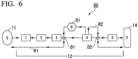
- the organic substance production system 60 of the sixth embodiment of the present invention includes a synthesis gas generation furnace 11, a synthesis gas purification unit 12, and an organic substance synthesis unit 14.
- the production system 60 is the same as the production systems 10, 20, 30, 40 and 50.
- the synthesis gas purification unit 12 includes a first purification unit for purifying the synthesis gas generated in the synthesis gas generation furnace 11, a second purification unit for purifying the synthesis gas purified by the first purification unit, and a detection unit for measuring the impurity concentration in the synthesis gas purified by the first purification unit.
- the detection unit feeds the synthesis gas purified in the first purification unit to the second purification unit when the impurity concentration is not higher than a predetermined value. On the other hand, when the impurity concentration is higher than the predetermined value, the detection unit returns the synthesis gas purified in the first purification unit to the first purification unit or the synthesis gas generation furnace.
- the predetermined value of the impurity concentration can be set, for example, in view of the adverse effect on the microorganisms as described above.
- the synthesis gas purification unit 12 includes a scrubber 1, a gas chiller 2, a desulfurization tank 3, a PSA 4, an activated carbon tank 5, a first detector D1, a second detector D2, a first return pipe R1, and a second return pipe R2, which are sequentially connected between the synthesis gas generation furnace 11 and the organic substance synthesis unit 14. These are connected via piping denoted by arrows in the drawing.
- a method 60 which can be mentioned as an example of embodiments in which an organic substance is produced using the organic substance production system 60 includes a step of generating the synthesis gas in the synthesis gas generation furnace 11, a step of purifying the synthesis gas in the synthesis gas purification unit 12, and a step of generating an organic substance from the purified synthesis gas in the organic substance synthesis unit 14.
- synthesis gas purification step first, a step of purifying the synthesis gas from the synthesis gas generation furnace 11 with the first purification unit to reduce the impurity concentration of the synthesis gas in the first purification unit, and a step of measuring the impurity concentration in the synthesis gas purified in the first purification unit by the detection unit (detection step) are performed.
- the synthesis gas purified in the first purification unit is fed to the second purification unit to further purify the synthesis gas.
- the synthesis gas purified in the first purification unit is returned to the first purification unit or the synthesis gas generation furnace.
- the predetermined value of the impurity concentration can be set, for example, in view of the adverse effect on the microorganisms as described above.
- the synthesis gas from the synthesis gas generation furnace 11 is treated with the scrubber 1, the gas chiller 2 and the desulfurization tank 3, and then the concentration of impurities, such as H 2 S, contained in the obtained synthesis gas is measured by the detector D1.
- the synthesis gas is fed into the PSA 4, or the synthesis gas is fed into the first dilution tank B1.
- the synthesis gas is fed into the first dilution tank B1 and mixed with a synthesis gas having an impurity concentration not higher than the predetermined value, or the synthesis gas is returned to the synthesis gas generation furnace 11 via the first return pipe R1.
- the predetermined value of the impurity concentration can be set, for example, in view of the adverse effect on the microorganisms as described above.
- the synthesis gas having a high impurity concentration is diluted in the same manner as in the above-described production method 50, and the resulting synthesis gas with reduced impurity concentration is fed from the first dilution tank B1 to the PSA 4.
- the synthesis gas is returned to the synthesis gas generation furnace 11 via the first return pipe R1.
- any one or more of the scrubber 1, the gas chiller 2 and the desulfurization tank 3 is the first purification unit, and the PSA 4 is the second purification unit.
- the concentration of various impurities contained in the synthesis gas from the PSA 4 is measured by the second detector D2.
- the synthesis gas is fed into the activated carbon tank 5, or the synthesis gas is fed into the organic substance synthesis unit 14.
- the synthesis gas is returned to the PSA 4 via the second return pipe R2. Then, the returned synthesis gas is treated again in the PSA 4 to reduce the impurity concentration thereof, followed by measuring the impurity concentration in the synthesis gas again by the second detector D2.
- the synthesis gas is fed into the activated carbon tank 5 or the organic substance synthesis unit 14.
- the predetermined value of the impurity concentration can be set, for example, in view of the adverse effect on the microorganisms as described above.
- any one or more of the scrubber 1, the gas chiller 2, the desulfurization tank 3, and the PSA 4 is the first purification unit
- the activated carbon tank 5 is the second purification unit.
- TSA and PSA may be used in addition to the activated carbon tank 5, or the activated carbon tank 5 may be replaced by either one or both of TSA and PSA.
- the number of TSA and PSA to be added or to replace may be one, or two or more.
- two or more activated carbon tanks 5 may be used.
- a gas treatment facility may be further provided on a downstream side of the system.
- such a gas treatment facility may be a metal catalyst tank for removing oxygen or acetylene, a filter for preventing scattering of finely divided activated carbon, a pressure regulator, or the like.
- synthesis gas was produced and purified for producing ethanol.
- the capacities of the first purification unit and the second purification unit were 90 L each.
- Activated carbon type: 4 GS-S manufactured by Tsurumicoal Co., Ltd. was filled into each of the first purification unit and the second purification unit.
- the flow rate at which the synthesis gas obtained by partial oxidation of waste was fed to the first purification unit was 5 Nm 3 /min.
- a detector for detecting the concentration of benzene was installed at the inlet (point A) of the first purification unit, the inlet (point B) of the first purification unit and the outlet (point C) of the second purification unit, and the concentration of benzene was constantly monitored.
- the detector installed at point B corresponds to the detector 12b of the production system 10 in FIG. 1 .
- the synthesis gas from the first purification unit was fed to the fermentor of the organic substance synthesis unit 14, and when the benzene concentration was higher than the threshold value (20 ppm), the synthesis gas from the first purification unit was fed to the second purification unit.
- Table 1 shows the benzene concentrations at points A, B and C at times 1 to 4. The blank cells in Table 1 indicate that the synthesis gas was not sent to point C.
- Time Benzene concentration (ppm) at point A Benzene concentration (ppm) at point B Benzene concentration (ppm) at point C 1 1300 10 2 4200 40 Less than 5 3 1800 18 4 6000 70 10
- the synthesis gas was fed from the first purification unit to the fermentor while bypassing the second purification unit.
- the synthesis gas from the first purification unit was fed to the fermentor via the second purification unit.
- the period of time during which the benzene concentration at point B exceeded 20 ppm as in times 2 and 4 was 280 hours. Accordingly, the period of time during which the second purification unit was used was 280 hours (about 6.5%) out of 4300 hours. Thus, in this case, deterioration of the activated carbon in the second purification unit was able to be suppressed more than the case of using the first and second purification units over the entire period of 4300 hours.
- synthesis gas was produced and purified for producing ethanol.
- the PSA 4 was installed downstream of the desulfurization tank 3, and the activated carbon tank 5 was further provided downstream of the PSA 4. Further, at a position upstream of the desulfurization tank 3, a detector D1 for measuring the concentration of hydrogen sulfide, a flow path leading to the desulfurization tank 3, and a flow path directly connected to the PSA 4 while bypassing (skipping) the desulfurization tank 3 were provided.
- the PSA 4 can accommodate therein various types of adsorbent/absorbent.
- the selection of appropriate adsorbent/absorbent and the application of pressure swing enabled adsorption/ absorption of even a small amount of hydrogen sulfide. Therefore, even if several tens of ppm of hydrogen sulfide remains in the synthesis gas to be fed to the PSA 4, the synthesis gas can be treated with only the PSA 4 without using the desulfurization tank 3.
- the concentration of hydrogen sulfide contained in the synthesis gas was measured at the inlet of the desulfurization tank 3 by the detector D1, and only when a concentration exceeding 50 ppm (predetermined threshold value) was detected, the synthesis gas was fed to the desulfurization tank 3. On the other hand, when a concentration of not higher than 50 ppm was detected, the synthesis gas was sent to the PSA 4.
- Example 2 Using a production system which was the same as in Example 2 except that the production system was not provided with a flow path directly connected to the PSA 4 while bypassing the desulfurization tank 3 and a detector D1, synthesis gas was produced and purified for producing ethanol.
- Example 2 In the production system of Example 2, the synthesis gas was not allowed to flow into the desulfurization tank 3 unless the hydrogen sulfide was contained at a high concentration in the synthesis gas; therefore, the period of time during which the gas was allowed to flow through the desulfurization tank 3 in Example 2 was short, as compared to that in Comparative Example 2A.
Landscapes
- Chemical & Material Sciences (AREA)
- Engineering & Computer Science (AREA)
- Organic Chemistry (AREA)
- Combustion & Propulsion (AREA)
- Life Sciences & Earth Sciences (AREA)
- Zoology (AREA)
- Chemical Kinetics & Catalysis (AREA)
- General Chemical & Material Sciences (AREA)
- Wood Science & Technology (AREA)
- Biotechnology (AREA)
- Health & Medical Sciences (AREA)
- Oil, Petroleum & Natural Gas (AREA)
- Bioinformatics & Cheminformatics (AREA)
- General Health & Medical Sciences (AREA)
- Genetics & Genomics (AREA)
- General Engineering & Computer Science (AREA)
- Biochemistry (AREA)
- Microbiology (AREA)
- Inorganic Chemistry (AREA)
- Analytical Chemistry (AREA)
- Sustainable Development (AREA)
- Biomedical Technology (AREA)
- Preparation Of Compounds By Using Micro-Organisms (AREA)
- Processing Of Solid Wastes (AREA)
- Industrial Gases (AREA)
- Separation Of Gases By Adsorption (AREA)
- Apparatus Associated With Microorganisms And Enzymes (AREA)
- Organic Low-Molecular-Weight Compounds And Preparation Thereof (AREA)
- Treating Waste Gases (AREA)
Abstract
Description
- The present invention relates to a system for producing an organic substance and a method for producing an organic substance. Priority is claimed on
PCT/JP2016/067225 - A method is proposed, which produces an organic substance such as ethanol by allowing anaerobic microorganisms to metabolize a carbon monoxide-containing synthesis gas derived from gas discharged from manufacturing processes for chemical materials, steels or the like (see, for example, Patent Document 1).
- Patent Document 1:
US Patent No. 8211679 - However, a system for producing organic substances by microbial metabolism from synthetic gas obtained by partially oxidizing general waste collected from households, commercial establishments, etc. has the following problems.
- For commercial implementation of the production, the system is desired to include a synthesis gas generation furnace that continuously feed a synthesis gas to downstream of the system; a synthesis gas purification unit for reducing the impurity concentration of the synthesis gas; and an organic substance synthesis unit for generating an organic substance by microbial metabolism from the purified synthetic gas.
- In the synthesis gas generation furnace, the synthesis gas obtained by partial oxidation of the general waste includes impurities other than synthesis gas, such as hydrogen sulfide, aromatic organic compounds, oxygen and the like. Since some of these impurities are harmful to the microorganisms, it is desirable to remove such impurities in the synthesis gas purification unit.
- However, since general wastes are collected from a large number of households and commercial establishments, the contents thereof are not constant, so that the composition and concentration of the impurities contained in the unpurified synthesis gas obtained by partial oxidation tend to fluctuate largely within a few minutes to several hours. For this reason, when a synthesis gas which is beyond the processing capacity of the purification apparatus constituting the synthesis gas purification unit is supplied, impurities may flow into the organic substance synthesis unit or may cause performance deterioration or breakage of the purification apparatus.
- On the other hand, in order to avoid the above problem, if purification apparatuses constituting the purification unit are installed excessively in preparation for generation of larger amount of impurities than usual, the facility cost becomes excessive and the commercialization becomes difficult.
- The present invention has been made in view of the above circumstances, and it is an object of the present invention to provide an organic substance production system and an organic substance production method which are capable of coping with a change in composition and concentration of impurities contained in a synthesis gas obtained by partial oxidation of waste.
-
- [1] A system for producing an organic substance, including: a synthesis gas generation furnace for producing a synthesis gas by partially oxidizing a waste including a carbon source; a synthesis gas purification unit which is connected to the synthesis gas generation furnace and purifies the synthesis gas generated in the synthesis gas generation furnace to reduce an impurity concentration in the synthesis gas; and an organic substance synthesis unit which is connected to the synthesis gas purification unit and generates an organic substance from the synthesis gas purified in the synthesis gas purification unit, wherein the synthesis gas purification unit includes: a first purification unit for purifying the synthesis gas; a second purification unit for purifying the synthesis gas purified in the first purification unit; a detection unit for measuring an impurity concentration in the synthesis gas purified in the first purification unit, wherein the detection unit is configured to: feed the synthesis gas purified in the first purification unit to a part positioned downstream of the second purification unit while bypassing the second purification unit when the impurity concentration is not higher than a predetermined value, or feed the synthesis gas purified in the first purification unit to the second purification unit when the impurity concentration is higher than the predetermined value.
- [2] A system for producing an organic substance, including: a synthesis gas generation furnace for producing a synthesis gas by partially oxidizing a waste including a carbon source; a synthesis gas purification unit which is connected to the synthesis gas generation furnace and purifies the synthesis gas generated in the synthesis gas generation furnace to reduce an impurity concentration in the synthesis gas; and an organic substance synthesis unit which is connected to the synthesis gas purification unit and generates an organic substance from the synthesis gas purified in the synthesis gas purification unit, wherein the synthesis gas purification unit includes: a first purification unit for purifying the synthesis gas; a second purification unit for purifying the synthesis gas purified in the first purification unit, which has a higher ability to reduce an impurity concentration than the first purification unit; and a detection unit for measuring an impurity concentration in the synthesis gas before being purified in the first purification unit and the second purification unit, wherein the detection unit is configured to: feed the synthesis gas to the first purification unit when the impurity concentration is not higher than a predetermined value, or feed the synthesis gas to the second purification unit when the impurity concentration is higher than the predetermined value.
- [3] A system for producing an organic substance, including: a synthesis gas generation furnace for producing a synthesis gas by partially oxidizing a waste including a carbon source; a synthesis gas purification unit connected to the synthesis gas generation furnace and purifying the synthesis gas generated in the synthesis gas generation furnace to reduce an impurity concentration in the synthesis gas; and an organic substance synthesis unit connected to the synthesis gas purification unit to generate an organic substance from the synthesis gas purified in the synthesis gas purification unit, wherein the synthesis gas purification unit includes: a first purification unit for purifying the synthesis gas; a second purification unit for purifying the synthesis gas purified in the first purification unit; a mixing unit for sequentially receiving the synthesis gas from the first purification unit, mixing together the synthesis gas received earlier and the synthesis gas received later, and feeding resulting synthesis gas to the second purification unit; and a detection unit for measuring an impurity concentration in the synthesis gas purified in the first purification unit, wherein the detection unit is configured to: feed the synthesis gas purified in the first purification unit to the second purification unit or the mixing unit when the impurity concentration is not higher than a predetermined value, or feed the synthesis gas purified in the first purification unit to the mixing unit when the impurity concentration is higher than the predetermined value, to thereby mix the synthesis gas with the synthesis gas with an impurity concentration not higher than the predetermined value.
- [4] A system for producing an organic substance, including: a synthesis gas generation furnace for producing a synthesis gas by partially oxidizing a waste including a carbon source; a synthesis gas purification unit connected to the synthesis gas generation furnace and purifying the synthesis gas generated in the synthesis gas generation furnace to reduce an impurity concentration in the synthesis gas; and an organic substance synthesis unit connected to the synthesis gas purification unit to generate an organic substance from the synthesis gas purified in the synthesis gas purification unit, wherein the synthesis gas purification unit includes: a first purification unit for purifying the synthesis gas; a second purification unit for purifying the synthesis gas purified in the first purification unit; a detection unit for measuring an impurity concentration in the synthesis gas purified in the first purification unit, wherein the detection unit is configured to: feed the synthesis gas purified in the first purification unit to the second purification unit when the impurity concentration is not higher than a predetermined value, or return the synthesis gas purified in the first purification unit to the first purification unit or the synthesis gas generation furnace when the impurity concentration is higher than a predetermined value.
- [5] The system according to any one of [1] to [4], wherein the predetermined value of the impurity concentration is in a range of concentration that adversely affects anaerobic bacteria that produce the organic substance in the organic substance synthesis unit.
- [6] The system according to any one of [1] to [5], wherein the first purification unit is a pressure swing adsorption apparatus or a temperature swing adsorption apparatus.
- [7] The system according to any one of [1] to [6], wherein the second purification unit includes activated carbon.
- [8] A method for producing an organic substance using the organic substance production system according to [1], which includes: a step of generating a synthesis gas in the synthesis gas generation furnace; a step of purifying the synthesis gas in the synthesis gas purification unit; and a step of generating an organic substance from the purified synthesis gas in the organic substance synthesis unit, wherein the step of purifying the synthesis gas purification includes: a step of purifying the synthesis gas in the first purification unit; a step of measuring an impurity concentration in the synthesis gas purified in the first purification unit by the detection unit, a step of: feeding the synthesis gas purified in the first purification unit to a part positioned downstream of the second purification unit while bypassing the second purification unit when the impurity concentration is not higher than a predetermined value, or feeding the synthesis gas purified in the first purification unit to the second purification unit when the impurity concentration is higher than the predetermined value, thereby purifying synthesis gas in the second purification unit, and feeding the synthesis gas purified in the second purification unit to a part positioned downstream of the second purification unit.
- [9] A method for producing an organic substance using the organic substance production system according to [2], which includes: a step of generating a synthesis gas in the synthesis gas generation furnace; a step of purifying the synthesis gas in the synthesis gas purification unit; and a step of generating an organic substance from the purified synthesis gas in the organic substance synthesis unit, wherein the step of purifying the synthesis gas purification includes: a step of measuring an impurity concentration in the synthesis gas by the detection unit, a step of: feeding the synthesis gas to the first purification unit when the impurity concentration is not higher than a predetermined value, thereby purifying the synthesis gas, or feeding the synthesis gas to the second purification unit when the impurity concentration is higher than a predetermined value, thereby purifying the synthesis gas.
- [10] A method for producing an organic substance using the organic substance production system according to [3], which includes: a step of generating a synthesis gas in the synthesis gas generation furnace; a step of purifying the synthesis gas in the synthesis gas purification unit; and a step of generating an organic substance from the purified synthesis gas in the organic substance synthesis unit, wherein the step of purifying the synthesis gas purification includes: a step of purifying the synthesis gas in the first purification unit; a step of measuring an impurity concentration in the synthesis gas purified in the first purification unit by the detection unit, and a step of: feeding the synthesis gas purified in the first purification unit to the second purification unit or the mixing unit when the impurity concentration is not higher than a predetermined value, or feeding the synthesis gas purified in the first purification unit to the mixing unit when the impurity concentration is higher than the predetermined value, to thereby mix the synthesis gas with the synthesis gas with an impurity concentration not higher than the predetermined value.
- [11] A method for producing an organic substance using the organic substance production system according to [4], which includes: a step of generating a synthesis gas in the synthesis gas generation furnace; a step of purifying the synthesis gas in the synthesis gas purification unit; and a step of generating an organic substance from the purified synthesis gas in the organic substance synthesis unit, wherein the step of purifying the synthesis gas purification includes: a step of purifying the synthesis gas in the first purification unit; a step of measuring an impurity concentration in the synthesis gas purified in the first purification unit by the detection unit, and a step of: feeding the synthesis gas purified in the first purification unit to the second purification unit when the impurity concentration is not higher than a predetermined value, or returning the synthesis gas purified in the first purification unit to the first purification unit or the synthesis gas generation furnace when the impurity concentration is higher than a predetermined value.
- [12] The method according to any one of [8] to [11], wherein the predetermined value of the impurity concentration is in a range of concentration that adversely affects anaerobic bacteria that produce the organic substance in the organic substance synthesis unit.
- According to the organic substance production system and organic substance production method of the present invention, it is possible to detect fluctuations in composition and concentration of impurities contained in an unpurified synthesis gas obtained by partial oxidation of waste, and to promptly change the process flow in the purification unit in accordance with the fluctuation, whereby the impurity concentration can be reduced with an optimum device configuration. This makes it possible to easily commercialize the organic substance production system and method of the present invention.
-
-
FIG. 1 is a schematic view of the organicsubstance production system 10 according to the first embodiment of the present invention. -
FIG. 2 is a schematic view of the organicsubstance production system 20 according to the second embodiment of the present invention. -
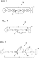
FIG. 3 is a schematic view of the organicsubstance production system 30 according to the third embodiment of the present invention. -
FIG. 4 is a schematic view of the organicsubstance production system 40 according to the fourth embodiment of the present invention. -
FIG. 5 is a schematic view of the organicsubstance production system 50 according to the fifth embodiment of the present invention. -
FIG. 6 is a schematic view of the organicsubstance production system 60 according to the sixth embodiment of the present invention. - Hereinbelow, examples of the preferred embodiments of the present invention are described, referring to the annexed drawings. In the drawings, components having substantially the same functions are denoted with the same reference numerals.
- As shown in
FIG. 1 , the organicsubstance production system 10 according to the first embodiment of the present invention includes: a synthesisgas generation furnace 11 for producing a synthesis gas by partially oxidizing a waste including a carbon source; a synthesisgas purification unit 12 which is connected to the synthesisgas generation furnace 11 and purifies the synthesis gas generated in the synthesisgas generation furnace 11 to reduce an impurity concentration in the synthesis gas; and an organicsubstance synthesis unit 14 which is connected to the synthesisgas purification unit 12 and generates an organic substance from the synthesis gas purified in the synthesisgas purification unit 12. - The waste used to obtain the synthesis gas in the synthesis
gas production furnace 11 is not particularly limited as long as it contains a carbon source. Examples of the waste include those which can be incinerated, such as domestic waste and general industrial waste. Examples of the carbon source include resin waste materials such as plastic and rubber. As the synthesisgas generation furnace 11, any known furnaces which can generate a synthesis gas by partial oxidation of the waste can be used. Generally, the synthesis gas obtained by partial oxidation of the waste contains carbon monoxide, hydrogen gas, nitrogen gas and the like. - The synthesis gas obtained in the synthesis
gas generation furnace 11 may contain impurities, examples of which include as hydrogen sulfide, carbonyl oxide, NOx, SOx, hydrogen fluoride, oxygen, ammonia, hydrogen cyanide, hydrocarbons such as methane, propane, propylene, acetylene, ethylene, ethane, isobutane and the like, aliphatic oxygen compounds such as dimethyl ether, formaldehyde, methyl formate and the like, aromatic organic compounds such as benzene, toluene, xylene, methylbenzene, naphthalene and the like, and tar. The type and concentration of impurities can vary greatly depending on the type of waste to be partially oxidized. - In the synthesis
gas purification unit 12 to which the synthesis gas generated in the synthesisgas generation furnace 11 is fed, two or more known purification apparatuses for reducing the concentration of one or more types of the above-mentioned impurities contained in the synthesis gas are provided. - The synthesis
gas purification unit 12 includes afirst purification unit 12a for purifying the synthesis gas, asecond purification unit 12c for purifying the synthesis gas purified by thefirst purification unit 12a, and adetection unit 12b for measuring the impurity concentration in the synthesis gas purified by thefirst purification unit 12a. - The purification units provided in the synthesis
gas purification unit 12 are connected by piping indicated by arrows in the drawing. Thedetection unit 12b is connected via piping between thefirst purification unit 12a, thesecond purification unit 12c and the organicsubstance synthesis unit 14, and a pipe on the downstream side of thedetection unit 12b is branched. Thefirst purification unit 12a is connected to thesecond purification unit 12c and the organicsubstance synthesis unit 14 via thedetection unit 12b. Thesecond purification unit 12c is connected to thedetection unit 12b and the organicsubstance synthesis unit 14. - The synthesis gas from the synthesis
gas generation furnace 11 is first purified in thefirst purification unit 12a, and its impurity concentration is reduced. Then, the synthesis gas is fed to thedetection unit 12b. - The
detection unit 12b measures an impurity concentration in the synthesis gas fed from thefirst purification unit 12a. When the impurity concentration is not higher than a predetermined value (predetermined threshold value), thedetection unit 12b feeds the synthesis gas purified by thefirst purification unit 12a into a fermenter of the organicsubstance synthesis unit 14 positioned downstream of thesecond purification unit 12c, while bypassing thesecond purification unit 12c. On the other hand, when the impurity concentration is higher than the predetermined value, thedetection unit 12b sends the synthesis gas purified by thefirst purification unit 12a to thesecond purification unit 12c. - The above-stated predetermined value of the impurity concentration can be defined, for example, as a range of concentration that is known to adversely affect the microorganisms that produce the organic substance in the organic
substance synthesis unit 14 with respect to each of various impurities. The concentration range is determined in view of a combination of the type of impurities and the type of microorganisms. The expression "adversely affect" refers to any undesirable phenomena such as microbial death, decreased proliferative ability, decreased utilization rate, decreased productivity of a substance of interest, and the like. - Examples of impurities which adversely affect microorganisms such as anaerobic bacteria which produce an organic substance from the synthesis gas include methane, acetylene, ethylene, ethane, tar, benzene, toluene, ethylbenzene, xylene, ammonia, hydrogen cyanide, NOx, hydrogen sulfide, carbonyl sulfide, naphthalene and the like. As a concentration at which the impurities adversely affect microorganisms, for example, it has been reported that an acetylene concentration of 1 ppm or more or an ethylene concentration of 1 ppm or more in the synthesis gas has an adverse effect on Clostridium bacteria (
US 9011578 B2 substance production system 10. - For example, specific impurities and concentrations adversely affecting microorganisms of the genus Clostridium may be as follows: acetylene: 5 ppm or more, ethylene: 50 ppm or more, HCN: 2 ppm or more, benzene: 1 ppm or more (
US9011578 B2 - The
second purification unit 12c purifies the fed synthesis gas and feeds the resulting synthesis gas having a reduced impurity concentration to the fermenter. - In the
production system 10, thefirst purification unit 12a and thesecond purification unit 12c are provided. Unless the impurity concentration is higher than the predetermined value, only thefirst purification unit 12a is used. Thesecond purification unit 12c is used only when the impurity concentration is higher than the predetermined value. Therefore, the impurity concentration reducing ability (purifying capacity) of thefirst purification unit 12a need not be higher, or may be even lower, than the impurity concentration reducing ability of thesecond purification unit 12c. - Thus, according to the
production system 10, it is possible to reduce the running cost of the synthesisgas purification unit 12, as compared to the case of providing one high-performance or large-scale purification unit for coping with the case where the concentration of impurities contained in the synthesis gas becomes extremely high. - From the viewpoint of suppressing the running cost of the synthesis
gas purification unit 12 to further lower level, it is preferable that thefirst purification unit 12a is a pressure swing adsorption apparatus (PSA) or a temperature swing adsorption apparatus (TSA), which can be operated at a low running cost. On the other hand, in order to surely suppress the supply of the synthesis gas having a high impurity concentration to the organicsubstance synthesis unit 14, it is preferable that thesecond purification unit 12c is an apparatus including activated carbon, which has a higher impurity concentration reducing ability than PSA and TSA. For example, when an aromatic compound such as benzene is taken as an example of the impurities, the activated carbon has a higher running cost than the above-mentioned PSA or the like, but has excellent benzene removing ability. Therefore, the activated carbon is expected to be capable of suppressing the concentration of the aromatic compound contained as an impurity in the synthesis gas to a lower level. - The synthesis gas purified by the synthesis
gas purification unit 12 is fed to a fermentor (microorganism incubator) of the organicsubstance synthesis unit 14. The microorganisms in the fermentor metabolize the synthesis gas to produce an organic substance. Here, the term "metabolize" embraces the concept of fermentation. Specific examples of the microorganisms suitably used in the case of producing alcohols such as ethanol include anaerobic carboxydotrophic bacteria and the like. More specific examples include anaerobic bacteria such as Clostridium bacteria, Moorella bacteria, Acetobacterium bacteria, Carboxydocella sporoducens sp. Nov., Rhodopseudomonas gelatinosa, Eubacterium limosum, and Butyribacterium methylotrophicum. - Examples of the Clostridium bacteria include Clostridium ljungdahlii, Clostridium autoethanogenum, Clostridium carboxidivorans, Clostridium ragsdalei (Kopke M. et al., Appl. Environ. Microbiol. 2011, 77 (15), 5467-5475), and Clostridium thermoaceticum. Examples of the Moorella bacteria include Moorella thermoacetica (Pierce EG. Et al., Environ. Microbiol. 2008, 10, 2550-2573). Examples of the Acetobacterium bacteria include Acetobacterium woodii (Dilling S. et al., Appl. Environ. Microbiol. 2007, 73 (11), 3630-3636).
- The organic
substance synthesis unit 14 is connected to apurifier 15 for obtaining an organic substance of interest from various organic substances generated by microorganisms. The product in the organicsubstance synthesis unit 14 is transferred to apurifier 15 and an organic substance of interest is obtained by a known purification method. - Examples of the organic substances produced by the
production system 10 include alcohols, organic acids, fatty acids, fats and oils, ketones, biomass, sugars and the like. More specific examples include ethanol, acetic acid, butanediol and the like. The use of the produced organic substance is not particularly limited, and examples thereof include raw materials for resins such as plastics and rubbers, and fuels. - The detector constituting the
detection unit 12b in theproduction system 10 described above is connected between thefirst purification unit 12a and thesecond purification unit 12c. However, the detector is not limited to be one which is connected between thefirst purification unit 12a and thesecond purification unit 12c, and may be of any configuration as long as the detector is connected so as to be able to detect (measure) the impurity concentration of the synthesis gas purified by thefirst purification unit 12a. For example, the detector may be connected to only thefirst purification unit 12a, while allowing a regulator (other than the detector) constituting thedetection unit 12b to distribute the synthesis gas purified by thefirst purification unit 12a. - In the synthesis
gas purification unit 12, in addition to the twopurification units first purification unit 12a or downstream of thesecond purification unit 12c. - A
method 10 which can be mentioned as an example of embodiments in which an organic substance is produced using the organicsubstance production system 10 includes a step of generating the synthesis gas in the synthesisgas generation furnace 11, a step of purifying the synthesis gas in the synthesisgas purification unit 12, and a step of generating an organic substance from the purified synthesis gas in the organicsubstance synthesis unit 14. - In the
production method 10, the step of purifying the synthesis gas includes a step of purifying the synthesis gas in thefirst purification section 12a, a step of measuring the impurity concentration in the synthesis gas purified in thefirst purification section 12a by thedetection unit 12b (detection step). - When the impurity concentration is not higher than the predetermined value, the synthesis gas purified by the
first purification unit 12a is fed into a fermentor of the organicsubstance synthesis unit 14 positioned downstream of thesecond purification unit 12c, while bypassing thesecond purification unit 12c. On the other hand, when the impurity concentration is higher than the predetermined value, the synthesis gas purified by thefirst purification unit 12a is fed into thesecond purification unit 12c to further purify the synthesis gas, and the synthesis gas purified by thesecond purification unit 12c is fed to the fermentor of the organicsubstance synthesis unit 14 positioned downstream of thesecond purification unit 12c. - The predetermined value of the impurity concentration can be set, for example, in view of the adverse effect on the microorganisms as described above.
- According to the
production method 10, it is possible to determine whether or not to use thesecond purification unit 12c depending on the impurity concentration measured in the detection step. Therefore, it is unnecessary to constantly operate thesecond purification unit 12c, which has a high impurity concentration reducing ability and is likely to increase cost, whereby the frequency of replacement and maintenance of thesecond purification unit 12c can be reduced and the running cost of the synthesisgas purification unit 12 can be reduced accordingly. - As shown in
FIG. 2 , the organicsubstance production system 20 of the second embodiment of the present invention includes a synthesisgas generation furnace 11, a synthesisgas purification unit 12, and an organicsubstance synthesis unit 14. In this respect, theproduction system 30 is the same as theproduction system 10. - The synthesis
gas purification unit 12 has two purification units that purify the synthesis gas generated in the synthesisgas generation furnace 11, that is, thefirst purification unit 12a and thesecond purification unit 12c having a higher impurity concentration reducing ability than thefirst purification unit 12a. Furthermore, the synthesisgas purification unit 12 has adetection unit 12b that measures the concentration of impurities contained in the synthesis gas before being purified by thefirst purification unit 12a and thesecond purification unit 12c. - The purification units provided in the synthesis
gas purification unit 12 are connected by piping indicated by arrows in the drawing. Thedetection unit 12b is connected via piping between the synthesisgas generation furnace 11, thefirst purification unit 12a and thesecond purification unit 12c, and a pipe on the downstream side of thedetection unit 12b is branched. Thefirst purification unit 12a and thesecond purification unit 12c are connected in parallel on the downstream side of thedetection unit 12b. The synthesisgas generation furnace 11 is connected to thefirst purification unit 12a and thesecond purification unit 12c via thedetection unit 12b. Thefirst purification unit 12a and thesecond purification unit 12c are independently connected to thedetection unit 12b and the organicsubstance synthesis unit 14. - The synthesis gas from the synthesis
gas generation furnace 11 is first fed to thedetection unit 12b. - The
detection unit 12b measures the impurity concentration in the synthesis gas from the synthesisgas generation furnace 11. When the impurity concentration is not higher than a predetermined value (predetermined threshold value), thedetection unit 12b feeds the synthesis gas into thefirst purification unit 12a having a lower impurity concentration reducing ability than thesecond purification unit 12c. On the other hand, when the impurity concentration is higher than the predetermined value, the synthesis gas is fed to thesecond purification unit 12c having a relatively high impurity concentration reducing ability. - The
first purification unit 12a and thesecond purification unit 12c purify the fed synthesis gas and feed the resulting synthesis gas having a reduced impurity concentration to the fermentor. - In the
production system 20, thefirst purification unit 12a and thesecond purification unit 12c can be selectively used according to the impurity concentration in the synthesis gas supplied from the synthesisgas generation furnace 11. Therefore, the impurity concentration reducing ability of thefirst purification unit 12a need not be higher, or may be even lower, than the impurity concentration reducing ability of thesecond purification unit 12c. - Thus, according to the
production system 20, it is possible to reduce the running cost of the synthesisgas purification unit 12, as compared to the case of providing one high-performance or large-scale purification unit for coping with the case where the concentration of impurities contained in the synthesis gas becomes extremely high. - The predetermined value of the impurity concentration can be set, for example, in view of the adverse effect on the microorganisms as described above.
- The detector constituting the
detection unit 12b in theproduction system 20 described above is connected between the synthesisgas generation furnace 11 and the twopurification units gas generation furnace 11 and the twopurification units purification units gas generation furnace 11, while allowing a regulator (other than the detector) constituting thedetection unit 12b to distribute the synthesis gas generated by the synthesisgas generation furnace 11. - In the synthesis
gas purification unit 12, in addition to the twopurification units detection unit 12b or downstream of thefirst purification unit 12a and thesecond purification unit 12c. - A
method 20 which can be mentioned as an example of embodiments in which an organic substance is produced using the organicsubstance production system 20 includes a step of generating the synthesis gas in the synthesisgas generation furnace 11, a step of purifying the synthesis gas in the synthesisgas purification unit 12, and a step of generating an organic substance from the purified synthesis gas in the organicsubstance synthesis unit 14. - In the synthesis gas purification step, first, a step of measuring the impurity concentration in the synthesis gas from the synthesis
gas generation furnace 11 by thedetection unit 12b (detection step) is performed. - When the impurity concentration measured in the detection step is not higher than a predetermined value, the synthesis gas is fed to the
first purification unit 12a to purify the synthesis gas. On the other hand, when the impurity concentration measured in the detection step is higher than the predetermined value, the synthesis gas is fed to thesecond purification unit 12c having a higher impurity concentration reducing ability than thefirst purification unit 12a, to reduce the impurity concentration of the synthesis gas. - The predetermined value of the impurity concentration can be set, for example, in view of the adverse effect on the microorganisms as described above.
- According to the
production method 20, it is possible to determine whether thefirst purification unit 12a or thesecond purification unit 12c should be used depending on the level of impurity concentration measured in the detection step. Therefore, it is unnecessary to constantly operate thesecond purification unit 12c, which has a high impurity concentration reducing ability and is likely to increase cost, whereby the frequency of replacement and maintenance of thesecond purification unit 12c can be reduced and the running cost of the synthesisgas purification unit 12 can be reduced accordingly. - As shown in
FIG. 3 , the organicsubstance production system 30 of the third embodiment of the present invention includes a synthesisgas generation furnace 11, a synthesisgas purification unit 12, and an organicsubstance synthesis unit 14. In this respect, theproduction system 30 is the same as theproduction system 10. - The synthesis
gas purification unit 12 includes ascrubber 1, agas chiller 2, adesulfurization tank 3, a pressure swing adsorption apparatus (PSA) 4, and an activatedcarbon tank 5, which are sequentially connected between the synthesisgas generation furnace 11 and the organicsubstance synthesis unit 14. These are connected via piping denoted by arrows in the drawing. - Examples of liquids usable for the
scrubber 1 include water, an acid, an alkali, and an organic solvent, and water is particularly preferable as the scrubbing liquid. - The synthesis
gas purification unit 12 has a detector D1. The detector D1 is connected via piping between thegas chiller 2 and thedesulfurization tank 3, and the pipe on the downstream side of the detector D1 is branched. Thegas chiller 2 is connected to thedesulfurization tank 3 and thePSA 4 via the detector D1. - Using the organic
substance production system 30, an organic substance can be produced in the same manner as in the case of theproduction system 10 described above. - Specifically, first, the synthesis gas fed from the synthesis
gas generation furnace 11 is treated with thescrubber 1 to thereby reduce the concentration of impurities, such as HCN, NH3 and soot, contained in the synthesis gas. Next, treatment with thegas chiller 2 is carried out to reduce the concentration of impurities such as moisture mixed into the gas in thescrubber 1 of the preceding stage, and naphthalene which easily solidifies. - Subsequently, the concentration of impurities such as H2S contained in the synthesis gas treated by the
gas chiller 2 is measured by the detector D1. - When the impurity concentration is not higher than a predetermined value, the synthesis gas is fed to the
PSA 4 provided downstream of thedesulfurization tank 3 while bypassing thedesulfurization tank 3. On the other hand, when the impurity concentration is higher than the predetermined value, the synthesis gas is fed into thedesulfurization tank 3 to reduce the concentrations of impurities such as H2S, and the resulting purified synthesis gas is fed to thePSA 4 installed downstream of the organicsubstance synthesis unit 14. - In the method exemplified above, at least one of the
scrubber 1 and thegas chiller 2 is thefirst purification unit 12a and thedesulfurization tank 3 is thesecond purification unit 12c. - The predetermined value of the impurity concentration can be set, for example, in view of the adverse effect on the microorganisms as described above.
- Besides being capable of removing H2S, the
PSA 4 can also reduce the concentration of impurities such as H2O, CO2, benzene, toluene and xylene. - Supplying a high concentration H2S to the
PSA 4 should be avoided, as it leads to performance degradation of thePSA 4 and the activated carbon provided downstream. - Subsequently, the synthesis gas treated in the
PSA 4 is treated in the activatedcarbon tank 5 and, if necessary, subjected to further treatment with another purification apparatus (not shown) to reduce the concentration of various remaining impurities left unremoved in the preceding processes. The resulting synthesis gas is fed to the organicsubstance synthesis unit 14. - As shown in
FIG. 4 , the organicsubstance production system 40 of the fourth embodiment of the present invention includes a synthesisgas generation furnace 11, a synthesisgas purification unit 12, and an organicsubstance synthesis unit 14. In this respect, theproduction system 40 is the same as theproduction system 20. - The synthesis
gas purification unit 12 includes ascrubber 1, agas chiller 2, adesulfurization tank 3, a pressure swing adsorption apparatus (PSA) 4, and an activatedcarbon tank 5, which are sequentially connected between the synthesisgas generation furnace 11 and the organicsubstance synthesis unit 14. These are connected via piping denoted by arrows in the drawing. - The synthesis
gas purification unit 12 has a detector D1. The detector D1 is connected via piping between thedesulfurization tank 3 and thePSA 4, and the pipe on the downstream side of the detector D1 is branched. Thegas chiller 2 is connected to thedesulfurization tank 3 and thePSA 4 via the detector D1. Thedesulfurization tank 3 and thePSA 4 are connected to the activatedcarbon tank 5. - Using the organic
substance production system 40, an organic substance can be produced in the same manner as in the case of theproduction system 20 described above. - Specifically, first, the synthesis gas from the synthesis
gas generation furnace 11 is treated with thescrubber 1 and thegas chiller 2, and then the concentration of impurities, such as H 2S, contained in the obtained synthesis gas is measured by the detector D1. - When the impurity concentration is not higher than the predetermined value, the synthesis gas is fed into the
PSA 4 to reduce the impurity concentration of the synthesis gas. On the other hand, when the impurity concentration is higher than the predetermined value, the synthesis gas is fed to thedesulfurization tank 3 having a higher H 2S reducing ability than thePSA 4 to reduce the impurity concentration of the synthesis gas. - In the method exemplified above, the
PSA 4 is thefirst purification unit 12a and thedesulfurization tank 3 is thesecond purification unit 12c, when classified in terms of the H 2S reducing ability. - The predetermined value of the impurity concentration can be set, for example, in view of the adverse effect on the microorganisms as described above.
- Subsequently, the synthesis gas treated in the
desulfurization tank 3 or thePSA 4 is treated in the activatedcarbon tank 5 and, if necessary, further transferred to and treated in another purification apparatus (not shown) to reduce the concentration of the impurities. The resulting synthesis gas is fed to the organicsubstance synthesis unit 14. - As shown in
FIG. 5 , the organicsubstance production system 50 of the fifth embodiment of the present invention includes a synthesisgas generation furnace 11, a synthesisgas purification unit 12, and an organicsubstance synthesis unit 14. In this respect, theproduction system 50 is the same as theproduction systems - The synthesis
gas purification unit 12 includes: a first purification unit for purifying the synthesis gas generated in the synthesisgas generation furnace 11; a second purification unit for purifying the synthesis gas purified by the first purification unit; a mixing unit for sequentially receiving the synthesis gas from the first purification unit, mixing together the synthesis gas received earlier and the synthesis gas received later, and feeding the resulting synthesis gas to the second purification unit; and a detection unit for measuring the impurity concentration in the synthesis gas purified by the first purification unit. - When the impurity concentration is not higher than a predetermined value, the detection unit feeds the synthesis gas purified in the first purification unit to the second purification unit or the mixing unit. On the other hand, when the impurity concentration is higher than the predetermined value, the detection unit feeds the synthesis gas purified in the first purification unit to the mixing unit, to thereby mix the synthesis gas with the synthesis gas having an impurity concentration not higher than the predetermined value.
- The predetermined value of the impurity concentration can be set, for example, in view of the adverse effect on the microorganisms as described above.
- The synthesis
gas purification unit 12 of theproduction system 50 includes ascrubber 1, agas chiller 2, adesulfurization tank 3, aPSA 4, an activatedcarbon tank 5, a first dilution tank B1, a second dilution tank B2, a first detector D1, and a second detector D2, which are sequentially connected between the synthesisgas generation furnace 11 and the organicsubstance synthesis unit 14. These are connected via piping denoted by arrows in the drawing. - A
method 50 which can be mentioned as an example of embodiments in which an organic substance is produced using the organicsubstance production system 50 includes a step of generating the synthesis gas in the synthesisgas generation furnace 11, a step of purifying the synthesis gas in the synthesisgas purification unit 12, and a step of generating an organic substance from the purified synthesis gas in the organicsubstance synthesis unit 14. - In the synthesis gas purification step, first, a step of purifying the synthesis gas from the synthesis
gas generation furnace 11 with the first purification unit to reduce the impurity concentration of the synthesis gas in the first purification unit, and a step of measuring the impurity concentration in the synthesis gas purified in the first purification unit by the detection unit (detection step) are performed. - When the impurity concentration is not higher than a predetermined value, the synthesis gas purified in the first purification unit is fed to the second purification unit or the mixing unit. On the other hand, when the impurity concentration is higher than the predetermined value, the synthesis gas purified in the first purification unit is fed to the mixing unit, to thereby mix the synthesis gas with the synthesis gas having an impurity concentration not higher than the predetermined value.
- A specific example of an embodiment in which an organic substance is produced using the organic
substance production system 50 will be described below. - First, the synthesis gas from the synthesis
gas generation furnace 11 is treated with thescrubber 1, thegas chiller 2 and thedesulfurization tank 3, and then the concentration of impurities, such as H2S, contained in the obtained synthesis gas is measured by the detector D1. - When the impurity concentration is not higher than the predetermined value, the synthesis gas is fed into the
PSA 4 or the activatedcarbon tank 5, or the synthesis gas is fed into the first dilution tank B1. - When the impurity concentration is higher than the predetermined value, the synthesis gas is fed into the first dilution tank B1 and mixed with a synthesis gas having an impurity concentration not higher than the predetermined value. The above-stated synthesis gas having an impurity concentration not higher than the predetermined value, which is to be mixed here, may be a pre-fed synthesis gas that has been fed to the first dilution tank B1 beforehand, or a post-fed synthesis gas having an impurity concentration not higher than the predetermined value, which is fed later to the first dilution tank B1.
- By sequentially receiving the synthesis gas from the
desulfurization tank 3 at the first dilution tank B1 to allow homogenization of the composition of the resulting synthesis gas mixture in the first dilution tank B1, highly concentrated impurities that are suddenly or temporarily generated can be diluted. The synthesis gas mixture is fed from the first dilution tank B1 to thePSA 4. - According to the above configuration, it is possible to prevent the highly concentrated impurities having passed through the
desulfurization tank 3 from inflicting irreparable damage on the purification apparatus provided downstream. - In the method exemplified above, any one or more of the
scrubber 1, thegas chiller 2 and thedesulfurization tank 3 is the first purification unit, and thePSA 4 is the second purification unit. - Subsequently, as shown in
FIG. 5 , the concentration of various impurities contained in the synthesis gas from thePSA 4 is measured by the second detector D2. - When the impurity concentration is not higher than the predetermined value, the synthesis gas is fed into the activated
carbon tank 5, or the synthesis gas is fed into the second dilution tank B2. - When the impurity concentration is higher than the predetermined value, the synthesis gas is fed into the second dilution tank B2 and mixed with a synthesis gas having an impurity concentration not higher than the predetermined value. The above-stated synthesis gas having an impurity concentration not higher than the predetermined value, which is to be mixed here, may be a pre-fed synthesis gas that has been fed to the second dilution tank B2 beforehand, or a post-fed synthesis gas having an impurity concentration not higher than the predetermined value, which is fed later to the second dilution tank B2.
- The predetermined value of the impurity concentration can be set, for example, in view of the adverse effect on the microorganisms as described above.
- By sequentially receiving the synthesis gas from the
PSA 4 at the second dilution tank B2 to allow homogenization of the composition of the resulting synthesis gas mixture in the second dilution tank B2, highly concentrated impurities that are suddenly or temporarily generated can be diluted. The synthesis gas mixture is fed from the second dilution tank B2 to the activatedcarbon tank 5. - According to the above configuration, it is possible to prevent the highly concentrated impurities having passed through the
PSA 4 from inflicting irreparable damage on the purification apparatus provided downstream. - In the method exemplified above, any one or more of the
scrubber 1, thegas chiller 2, thedesulfurization tank 3, and thePSA 4 is the first purification unit, and the activatedcarbon tank 5 is the second purification unit. - Subsequently, the synthesis gas treated in the
desulfurization tank 3 or thePSA 4 is treated in the activatedcarbon tank 5 and, if necessary, further transferred to and treated in another purification apparatus (not shown) to reduce the concentration of the impurities. The resulting synthesis gas is fed to the organicsubstance synthesis unit 14. - As shown in
FIG. 6 , the organicsubstance production system 60 of the sixth embodiment of the present invention includes a synthesisgas generation furnace 11, a synthesisgas purification unit 12, and an organicsubstance synthesis unit 14. In this respect, theproduction system 60 is the same as theproduction systems - The synthesis
gas purification unit 12 includes a first purification unit for purifying the synthesis gas generated in the synthesisgas generation furnace 11, a second purification unit for purifying the synthesis gas purified by the first purification unit, and a detection unit for measuring the impurity concentration in the synthesis gas purified by the first purification unit. - The detection unit feeds the synthesis gas purified in the first purification unit to the second purification unit when the impurity concentration is not higher than a predetermined value. On the other hand, when the impurity concentration is higher than the predetermined value, the detection unit returns the synthesis gas purified in the first purification unit to the first purification unit or the synthesis gas generation furnace.
- The predetermined value of the impurity concentration can be set, for example, in view of the adverse effect on the microorganisms as described above.
- The synthesis
gas purification unit 12 includes ascrubber 1, agas chiller 2, adesulfurization tank 3, aPSA 4, an activatedcarbon tank 5, a first detector D1, a second detector D2, a first return pipe R1, and a second return pipe R2, which are sequentially connected between the synthesisgas generation furnace 11 and the organicsubstance synthesis unit 14. These are connected via piping denoted by arrows in the drawing. - A
method 60 which can be mentioned as an example of embodiments in which an organic substance is produced using the organicsubstance production system 60 includes a step of generating the synthesis gas in the synthesisgas generation furnace 11, a step of purifying the synthesis gas in the synthesisgas purification unit 12, and a step of generating an organic substance from the purified synthesis gas in the organicsubstance synthesis unit 14. - In the synthesis gas purification step, first, a step of purifying the synthesis gas from the synthesis
gas generation furnace 11 with the first purification unit to reduce the impurity concentration of the synthesis gas in the first purification unit, and a step of measuring the impurity concentration in the synthesis gas purified in the first purification unit by the detection unit (detection step) are performed. - When the impurity concentration measured in the detection step is not higher than a predetermined value, the synthesis gas purified in the first purification unit is fed to the second purification unit to further purify the synthesis gas. On the other hand, when the impurity concentration measured in the detection step is higher than the predetermined value, the synthesis gas purified in the first purification unit is returned to the first purification unit or the synthesis gas generation furnace.
- The predetermined value of the impurity concentration can be set, for example, in view of the adverse effect on the microorganisms as described above.
- A specific example of an embodiment in which an organic substance is produced using the organic
substance production system 60 will be described below. - First, the synthesis gas from the synthesis
gas generation furnace 11 is treated with thescrubber 1, thegas chiller 2 and thedesulfurization tank 3, and then the concentration of impurities, such as H 2S, contained in the obtained synthesis gas is measured by the detector D1. - When the impurity concentration is not higher than the predetermined value, the synthesis gas is fed into the
PSA 4, or the synthesis gas is fed into the first dilution tank B1. - When the impurity concentration is higher than the predetermined value, the synthesis gas is fed into the first dilution tank B1 and mixed with a synthesis gas having an impurity concentration not higher than the predetermined value, or the synthesis gas is returned to the synthesis
gas generation furnace 11 via the first return pipe R1. - The predetermined value of the impurity concentration can be set, for example, in view of the adverse effect on the microorganisms as described above.
- When the synthesis gas is fed into the first dilution tank B1, the synthesis gas having a high impurity concentration is diluted in the same manner as in the above-described
production method 50, and the resulting synthesis gas with reduced impurity concentration is fed from the first dilution tank B1 to thePSA 4. - However, when the first detector D1 detects an impurity concentration exceeding the dilution capacity of the first dilution tank B1, the synthesis gas is returned to the synthesis
gas generation furnace 11 via the first return pipe R1. - According to the above method, it is possible to prevent the highly concentrated impurities having passed through the
desulfurization tank 3 from inflicting irreparable damage on the purification apparatus provided downstream. - In the method exemplified above, any one or more of the
scrubber 1, thegas chiller 2 and thedesulfurization tank 3 is the first purification unit, and thePSA 4 is the second purification unit. - Subsequently, as shown in
FIG. 6 , the concentration of various impurities contained in the synthesis gas from thePSA 4 is measured by the second detector D2. - When the impurity concentration is not higher than the predetermined value, the synthesis gas is fed into the activated
carbon tank 5, or the synthesis gas is fed into the organicsubstance synthesis unit 14. - On the other hand, when the impurity concentration is higher than the predetermined value, the synthesis gas is returned to the
PSA 4 via the second return pipe R2. Then, the returned synthesis gas is treated again in thePSA 4 to reduce the impurity concentration thereof, followed by measuring the impurity concentration in the synthesis gas again by the second detector D2. When the impurity concentration is not higher than the predetermined value, the synthesis gas is fed into the activatedcarbon tank 5 or the organicsubstance synthesis unit 14. - According to the above configuration, it is possible to prevent the highly concentrated impurities having passed through the
PSA 4 from inflicting irreparable damage on the purification apparatus provided downstream. Further, unnecessary use of the activatedcarbon tank 5 can be avoided so as to prolong the service life of the activatedcarbon tank 5, which enables reduction of the running cost. - The predetermined value of the impurity concentration can be set, for example, in view of the adverse effect on the microorganisms as described above.
- In the method exemplified above, any one or more of the
scrubber 1, thegas chiller 2, thedesulfurization tank 3, and thePSA 4 is the first purification unit, and the activatedcarbon tank 5 is the second purification unit. - The elements, combinations thereof, etc. that are explained above in connection with the specific embodiments of the present invention are mere examples, and various alterations such as addition of conventional element, omission and substitution of any elements, etc. may be made as long as such alterations do not deviate from the gist of the present invention.
- For example, in the above-described
production systems carbon tank 5, or the activatedcarbon tank 5 may be replaced by either one or both of TSA and PSA. In this instance, the number of TSA and PSA to be added or to replace may be one, or two or more. In addition, two or more activatedcarbon tanks 5 may be used. Further, if necessary, a gas treatment facility may be further provided on a downstream side of the system. For example, such a gas treatment facility may be a metal catalyst tank for removing oxygen or acetylene, a filter for preventing scattering of finely divided activated carbon, a pressure regulator, or the like. - Using a production system which is the same as the
production system 10 ofFIG. 1 , synthesis gas was produced and purified for producing ethanol. - The capacities of the first purification unit and the second purification unit were 90 L each. Activated carbon (type: 4 GS-S) manufactured by Tsurumicoal Co., Ltd. was filled into each of the first purification unit and the second purification unit.
- The flow rate at which the synthesis gas obtained by partial oxidation of waste was fed to the first purification unit was 5 Nm 3/min.
- A detector (microGC, "490 micro GC", manufactured by GL Science Co., Ltd.) for detecting the concentration of benzene was installed at the inlet (point A) of the first purification unit, the inlet (point B) of the first purification unit and the outlet (point C) of the second purification unit, and the concentration of benzene was constantly monitored. The detector installed at point B corresponds to the
detector 12b of theproduction system 10 inFIG. 1 . Referring to the measured value in the detector at point B, when the benzene concentration was not higher than the predetermined threshold value (20 ppm), the synthesis gas from the first purification unit was fed to the fermentor of the organicsubstance synthesis unit 14, and when the benzene concentration was higher than the threshold value (20 ppm), the synthesis gas from the first purification unit was fed to the second purification unit. - Table 1 below shows the benzene concentrations at points A, B and C at
times 1 to 4. The blank cells in Table 1 indicate that the synthesis gas was not sent to point C.[Table 1] Time Benzene concentration (ppm) at point A Benzene concentration (ppm) at point B Benzene concentration (ppm) at point C 1 1300 10 2 4200 40 Less than 5 3 1800 18 4 6000 70 10 - As shown in Table 1, at
times times - As a result of operating the above production system for 4300 hours, the period of time during which the benzene concentration at point B exceeded 20 ppm as in
times - Using a production system which is the same as the
production system 30 ofFIG. 1 , synthesis gas was produced and purified for producing ethanol. - In the above production system, the
PSA 4 was installed downstream of thedesulfurization tank 3, and the activatedcarbon tank 5 was further provided downstream of thePSA 4. Further, at a position upstream of thedesulfurization tank 3, a detector D1 for measuring the concentration of hydrogen sulfide, a flow path leading to thedesulfurization tank 3, and a flow path directly connected to thePSA 4 while bypassing (skipping) thedesulfurization tank 3 were provided. - The
PSA 4 can accommodate therein various types of adsorbent/absorbent. The selection of appropriate adsorbent/absorbent and the application of pressure swing enabled adsorption/ absorption of even a small amount of hydrogen sulfide. Therefore, even if several tens of ppm of hydrogen sulfide remains in the synthesis gas to be fed to thePSA 4, the synthesis gas can be treated with only thePSA 4 without using thedesulfurization tank 3. - Using the above production system, the concentration of hydrogen sulfide contained in the synthesis gas was measured at the inlet of the
desulfurization tank 3 by the detector D1, and only when a concentration exceeding 50 ppm (predetermined threshold value) was detected, the synthesis gas was fed to thedesulfurization tank 3. On the other hand, when a concentration of not higher than 50 ppm was detected, the synthesis gas was sent to thePSA 4. - Using a production system which was the same as in Example 2 except that the production system was not provided with a flow path directly connected to the
PSA 4 while bypassing thedesulfurization tank 3 and a detector D1, synthesis gas was produced and purified for producing ethanol. - In the production system of Example 2, the synthesis gas was not allowed to flow into the
desulfurization tank 3 unless the hydrogen sulfide was contained at a high concentration in the synthesis gas; therefore, the period of time during which the gas was allowed to flow through thedesulfurization tank 3 in Example 2 was short, as compared to that in Comparative Example 2A. - On the other hand, in the production system of Comparative Example 2A, the synthesis gas was allowed to constantly pass through the
desulfurization tank 3, and the hydrogen sulfide was almost completely removed in thedesulfurization tank 3. As a result, the service life of thedesulfurization tank 3 in Comparative Example 2A was shortened to about 1/3 of that of thedesulfurization tank 3 in Example 2. -
- 10, 20, 30, 40, 50, 60:
- Production system
- 11:
- Synthesis gas generation furnace
- 12:
- Synthesis gas purification unit
- 12a:
- First purification unit
- 12b:
- Detection unit
- 12c:
- Second purification unit
- 14:
- Organic substance synthesis unit
- 15:
- Purifier
- D1, D2:
- Detector
- B1, B2:
- Dilution tank
- R1, R2:
- Return pipe
- 1:
- Scrubber
- 2:
- Gas chiller
- 3:
- Desulfurization tank
- 4:
- Pressure swing adsorption apparatus (PSA)
- 5:
- Activated carbon tank
Claims (12)
- A system for producing an organic substance, comprising:a synthesis gas generation furnace for producing a synthesis gas by partially oxidizing a waste comprising a carbon source;a synthesis gas purification unit which is connected to the synthesis gas generation furnace and purifies the synthesis gas generated in the synthesis gas generation furnace to reduce an impurity concentration in the synthesis gas; andan organic substance synthesis unit which is connected to the synthesis gas purification unit and generates an organic substance from the synthesis gas purified in the synthesis gas purification unit,wherein the synthesis gas purification unit comprises:a first purification unit for purifying the synthesis gas;a second purification unit for purifying the synthesis gas purified in the first purification unit;a detection unit for measuring an impurity concentration in the synthesis gas purified in the first purification unit,wherein the detection unit is configured to:feed the synthesis gas purified in the first purification unit to a part positioned downstream of the second purification unit while bypassing the second purification unit when the impurity concentration is not higher than a predetermined value, orfeed the synthesis gas purified in the first purification unit to the second purification unit when the impurity concentration is higher than the predetermined value.
- A system for producing an organic substance, comprising:a synthesis gas generation furnace for producing a synthesis gas by partially oxidizing a waste comprising a carbon source;a synthesis gas purification unit which is connected to the synthesis gas generation furnace and purifies the synthesis gas generated in the synthesis gas generation furnace to reduce an impurity concentration in the synthesis gas; andan organic substance synthesis unit which is connected to the synthesis gas purification unit and generates an organic substance from the synthesis gas purified in the synthesis gas purification unit,wherein the synthesis gas purification unit comprises:a first purification unit for purifying the synthesis gas;a second purification unit for purifying the synthesis gas purified in the first purification unit, which has a higher ability to reduce an impurity concentration than the first purification unit; anda detection unit for measuring an impurity concentration in the synthesis gas before being purified in the first purification unit and the second purification unit,wherein the detection unit is configured to:feed the synthesis gas to the first purification unit when the impurity concentration is not higher than a predetermined value, andfeed the synthesis gas to the second purification unit when the impurity concentration is higher than the predetermined value.
- A system for producing an organic substance, comprising:a synthesis gas generation furnace for producing a synthesis gas by partially oxidizing a waste comprising a carbon source;a synthesis gas purification unit which is connected to the synthesis gas generation furnace and purifies the synthesis gas generated in the synthesis gas generation furnace to reduce an impurity concentration in the synthesis gas; andan organic substance synthesis unit which is connected to the synthesis gas purification unit and generates an organic substance from the synthesis gas purified in the synthesis gas purification unit,wherein the synthesis gas purification unit comprises:a first purification unit for purifying the synthesis gas;a second purification unit for purifying the synthesis gas purified in the first purification unit;a mixing unit for sequentially receiving the synthesis gas from the first purification unit, mixing together the synthesis gas received earlier and the synthesis gas received later, and feeding resulting synthesis gas to the second purification unit; anda detection unit for measuring an impurity concentration in the synthesis gas purified in the first purification unit,wherein the detection unit is configured to:feed the synthesis gas purified in the first purification unit to the second purification unit or the mixing unit when the impurity concentration is not higher than a predetermined value, orfeed the synthesis gas purified in the first purification unit to the mixing unit when the impurity concentration is higher than the predetermined value, to thereby mix the synthesis gas with a synthesis gas having an impurity concentration not higher than the predetermined value.
- A system for producing an organic substance, comprising:a synthesis gas generation furnace for producing a synthesis gas by partially oxidizing a waste comprising a carbon source;a synthesis gas purification unit which is connected to the synthesis gas generation furnace and purifies the synthesis gas generated in the synthesis gas generation furnace to reduce an impurity concentration in the synthesis gas; andan organic substance synthesis unit which is connected to the synthesis gas purification unit and generates an organic substance from the synthesis gas purified in the synthesis gas purification unit,wherein the synthesis gas purification unit comprises:a first purification unit for purifying the synthesis gas;a second purification unit for purifying the synthesis gas purified in the first purification unit;a detection unit for measuring an impurity concentration in the synthesis gas purified in the first purification unit,wherein the detection unit is configured to:feed the synthesis gas purified in the first purification unit to the second purification unit when the impurity concentration is not higher than a predetermined value, orreturn the synthesis gas purified in the first purification unit to the first purification unit or the synthesis gas generation furnace when the impurity concentration is higher than the predetermined value.
- The system according to any one of claims 1 to 4, wherein the predetermined value of the impurity concentration is in a range of concentration that adversely affects anaerobic bacteria that produce the organic substance in the organic substance synthesis unit.
- The system according to any one of claims 1 to 5, wherein the first purification unit is a pressure swing adsorption apparatus or a temperature swing adsorption apparatus.
- The system according to any one of claims 1 to 6, wherein the second purification unit comprises activated carbon.
- A method for producing an organic substance using the system according to claim 1, which comprises:a step of generating a synthesis gas in the synthesis gas generation furnace;a step of purifying the synthesis gas in the synthesis gas purification unit; anda step of generating an organic substance from the purified synthesis gas in the organic substance synthesis unit,wherein the step of purifying the synthesis gas comprises:a step of purifying the synthesis gas in the first purification unit;a step of measuring an impurity concentration in the synthesis gas purified in the first purification unit by the detection unit; anda step of:feeding the synthesis gas purified in the first purification unit to a part positioned downstream of the second purification unit while bypassing the second purification unit when the impurity concentration is not higher than a predetermined value, orfeeding the synthesis gas purified in the first purification unit to the second purification unit when the impurity concentration is higher than the predetermined value, thereby purifying the synthesis gas in the second purification unit, and feeding the synthesis gas purified in the second purification unit to a part positioned downstream of the second purification unit.
- A method for producing an organic substance using the system according to claim 2, which comprises:a step of generating a synthesis gas in the synthesis gas generation furnace;a step of purifying the synthesis gas in the synthesis gas purification unit; anda step of generating an organic substance from the purified synthesis gas in the organic substance synthesis unit,wherein the step of purifying the synthesis gas comprises:a step of measuring an impurity concentration in the synthesis gas by the detection unit; anda step of:feeding the synthesis gas to the first purification unit when the impurity concentration is not higher than a predetermined value, thereby purifying the synthesis gas, orfeeding the synthesis gas to the second purification unit when the impurity concentration is higher than the predetermined value, thereby purifying the synthesis gas.
- A method for producing an organic substance using the system according to claim 3, which comprises:a step of generating a synthesis gas in the synthesis gas generation furnace;a step of purifying the synthesis gas in the synthesis gas purification unit; anda step of generating an organic substance from the purified synthesis gas in the organic substance synthesis unit,wherein the step of purifying the synthesis gas comprises:a step of purifying the synthesis gas in the first purification unit;a step of measuring an impurity concentration in the synthesis gas purified in the first purification unit by the detection unit; anda step of:feeding the synthesis gas purified in the first purification unit to the second purification unit or the mixing unit when the impurity concentration is not higher than a predetermined value, orfeeding the synthesis gas purified in the first purification unit to the mixing unit when the impurity concentration is higher than the predetermined value, to thereby mix the synthesis gas with a synthesis gas having an impurity concentration not higher than the predetermined value.
- A method for producing an organic substance using the system according to claim 4, which comprises:a step of generating a synthesis gas in the synthesis gas generation furnace;a step of purifying the synthesis gas in the synthesis gas purification unit; anda step of generating an organic substance from the purified synthesis gas in the organic substance synthesis unit,wherein the step of purifying the synthesis gas comprises:a step of purifying the synthesis gas in the first purification unit;a step of measuring an impurity concentration in the synthesis gas purified in the first purification unit by the detection unit; anda step of:feeding the synthesis gas purified in the first purification unit to the second purification unit when the impurity concentration is not higher than a predetermined value, orreturning the synthesis gas purified in the first purification unit to the first purification unit or the synthesis gas generation furnace when the impurity concentration is higher than the predetermined value.
- The method according to any one of claims 8 to 11, wherein the predetermined value of the impurity concentration is in a range of concentration that adversely affects anaerobic bacteria that produce the organic substance in the organic substance synthesis unit.
Applications Claiming Priority (2)
| Application Number | Priority Date | Filing Date | Title |
|---|---|---|---|
| PCT/JP2016/067225 WO2017212605A1 (en) | 2016-06-09 | 2016-06-09 | Apparatus for producing organic substance from waste, and method for producing organic substance from waste |
| PCT/JP2016/077516 WO2017212662A1 (en) | 2016-06-09 | 2016-09-16 | System for producing organic substance and method for producing organic substance |
Publications (3)
| Publication Number | Publication Date |
|---|---|
| EP3470497A1 true EP3470497A1 (en) | 2019-04-17 |
| EP3470497A4 EP3470497A4 (en) | 2019-12-18 |
| EP3470497B1 EP3470497B1 (en) | 2021-11-24 |
Family
ID=60213998
Family Applications (1)
| Application Number | Title | Priority Date | Filing Date |
|---|---|---|---|
| EP16904696.8A Active EP3470497B1 (en) | 2016-06-09 | 2016-09-16 | System for producing organic substance and method for producing organic substance |
Country Status (5)
| Country | Link |
|---|---|
| US (2) | US10865425B2 (en) |
| EP (1) | EP3470497B1 (en) |
| JP (3) | JP6097895B1 (en) |
| CN (1) | CN109563421A (en) |
| WO (2) | WO2017212605A1 (en) |
Cited By (1)
| Publication number | Priority date | Publication date | Assignee | Title |
|---|---|---|---|---|
| US12180430B2 (en) | 2018-07-25 | 2024-12-31 | Sekisui Chemical Co., Ltd. | Control device and control method |
Families Citing this family (9)
| Publication number | Priority date | Publication date | Assignee | Title |
|---|---|---|---|---|
| JP2019004753A (en) * | 2017-06-23 | 2019-01-17 | 積水化学工業株式会社 | Gas processing system and gas processing apparatus |
| FR3069787B1 (en) * | 2017-08-03 | 2019-08-09 | L'air Liquide, Societe Anonyme Pour L'etude Et L'exploitation Des Procedes Georges Claude | PROCESS FOR THE CONTINUOUS PRODUCTION OF A GASEOUS FLOW OF HYDROGEN |
| CA3090386A1 (en) * | 2018-02-12 | 2019-08-15 | Lanzatech, Inc. | Integrated process for filtering constituents from a gas stream |
| CN108676707A (en) * | 2018-04-13 | 2018-10-19 | 苏州爱绿环保科技有限公司 | A kind of house refuse production bionethanation system and biogas production method |
| WO2021060289A1 (en) * | 2019-09-24 | 2021-04-01 | 積水化学工業株式会社 | Method for producing purified gas, method for producing valuable material, gas purification device, and device for producing valuable material |
| WO2021149764A1 (en) | 2020-01-23 | 2021-07-29 | 積水化学工業株式会社 | Method for producing organic substance and device for producing organic substance |
| JP7708674B2 (en) * | 2020-01-23 | 2025-07-15 | 積水化学工業株式会社 | Organic substance manufacturing method and organic substance manufacturing device |
| JPWO2021193573A1 (en) * | 2020-03-24 | 2021-09-30 | ||
| EP4685222A1 (en) * | 2023-03-23 | 2026-01-28 | Sekisui Chemical Co., Ltd. | System for producing organic substance, device for producing organic substance, and method for producing organic substance |
Family Cites Families (16)
| Publication number | Priority date | Publication date | Assignee | Title |
|---|---|---|---|---|
| CA22A (en) * | 1869-08-25 | A. Frechette | Improvements in the gig saw | |
| JP4459003B2 (en) * | 2004-09-30 | 2010-04-28 | 株式会社東芝 | Waste treatment system |
| CN101190893B (en) * | 2006-11-20 | 2010-04-14 | 中国石油化学工业开发股份有限公司 | Equipment and method for purifying crude caprolactam water solution |
| AU2009215419B2 (en) * | 2008-02-20 | 2014-01-09 | Gtlpetrol Llc | Systems and processes for processing hydrogen and carbon monoxide |
| US8211679B2 (en) | 2008-02-25 | 2012-07-03 | Coskata, Inc. | Process for producing ethanol |
| CN101538483B (en) * | 2009-04-03 | 2013-04-17 | 中国科学院山西煤炭化学研究所 | Poly-generation technique for using coal gas and coke oven gas as raw materials |
| EP2267102A1 (en) * | 2009-06-24 | 2010-12-29 | CTU - Conzepte Technik Umwelt AG | System and method for manufacturing gas from a biomass gasification |
| PL3070170T3 (en) | 2010-01-14 | 2019-02-28 | Lanzatech New Zealand Limited | Fermentation of co2 by using an electrical potential |
| JP2012001441A (en) * | 2010-06-14 | 2012-01-05 | Sekisui Chem Co Ltd | Method for producing ethanol and system for producing ethanol |
| US8752390B2 (en) * | 2010-07-13 | 2014-06-17 | Air Products And Chemicals, Inc. | Method and apparatus for producing power and hydrogen |
| JP5591158B2 (en) * | 2011-03-07 | 2014-09-17 | 三菱重工業株式会社 | COS processing apparatus and COS processing method in product gas |
| US9155988B2 (en) * | 2013-03-14 | 2015-10-13 | Universal Laser Systems, Inc. | Multi-stage air filtration systems and associated apparatuses and methods |
| CN103146760A (en) * | 2013-03-18 | 2013-06-12 | 张其标 | High-efficiency, energy-saving and environment-friendly technology for fermentation and purification of biogas |
| EP3045538B1 (en) * | 2013-09-13 | 2019-03-20 | Sekisui Chemical Co., Ltd. | Device for manufacturing organic substance and method for manufacturing organic substance |
| WO2016017551A1 (en) * | 2014-07-29 | 2016-02-04 | 積水化学工業株式会社 | Device for producing organic materials from waste and method for producing organic materials from waste |
| JP6130817B2 (en) * | 2014-09-16 | 2017-05-17 | 積水化学工業株式会社 | Apparatus for producing organic substance, method for producing organic substance, synthesis gas production method, and synthesis gas production apparatus |
-
2016
- 2016-06-09 WO PCT/JP2016/067225 patent/WO2017212605A1/en not_active Ceased
- 2016-09-16 JP JP2016574021A patent/JP6097895B1/en active Active
- 2016-09-16 US US16/307,674 patent/US10865425B2/en active Active
- 2016-09-16 WO PCT/JP2016/077516 patent/WO2017212662A1/en not_active Ceased
- 2016-09-16 EP EP16904696.8A patent/EP3470497B1/en active Active
- 2016-09-16 CN CN201680088125.1A patent/CN109563421A/en active Pending
- 2016-12-16 JP JP2016244617A patent/JP6225239B1/en not_active Expired - Fee Related
-
2017
- 2017-05-23 JP JP2017101651A patent/JP2017216997A/en not_active Ceased
-
2020
- 2020-11-05 US US17/090,164 patent/US11525147B2/en active Active
Cited By (1)
| Publication number | Priority date | Publication date | Assignee | Title |
|---|---|---|---|---|
| US12180430B2 (en) | 2018-07-25 | 2024-12-31 | Sekisui Chemical Co., Ltd. | Control device and control method |
Also Published As
| Publication number | Publication date |
|---|---|
| JP2017216997A (en) | 2017-12-14 |
| JP2017216992A (en) | 2017-12-14 |
| JP6225239B1 (en) | 2017-11-01 |
| CN109563421A (en) | 2019-04-02 |
| EP3470497A4 (en) | 2019-12-18 |
| EP3470497B1 (en) | 2021-11-24 |
| WO2017212662A1 (en) | 2017-12-14 |
| US20210054419A1 (en) | 2021-02-25 |
| US11525147B2 (en) | 2022-12-13 |
| WO2017212605A1 (en) | 2017-12-14 |
| JP6097895B1 (en) | 2017-03-15 |
| US20190256874A1 (en) | 2019-08-22 |
| US10865425B2 (en) | 2020-12-15 |
| JPWO2017212662A1 (en) | 2018-06-21 |
Similar Documents
| Publication | Publication Date | Title |
|---|---|---|
| US11525147B2 (en) | System for producing organic substance and method for producing organic substance | |
| US11713443B2 (en) | Integrated process for filtering constituents from a gas stream | |
| US20230407346A1 (en) | Secondary acetate fermentation | |
| JP2023011698A (en) | Processes and systems for product recovery and cell recycling | |
| Nie et al. | Comparison of water scrubbing and propylene carbonate absorption for biogas upgrading process | |
| KR102737235B1 (en) | Low pressure separator having internal distributor and its use | |
| CN102665872B (en) | Process for processing hot syngas streams for conversion to chemical products by removal of ammonia and COS | |
| US20220325218A1 (en) | Method of controlling gas fermentation platform for improved conversion of carbon dioxide into products | |
| US8303849B2 (en) | HCN removal from syngas using chemical and biological treatment | |
| Robazza et al. | Energy recovery from syngas and pyrolysis wastewaters with anaerobic mixed cultures | |
| US11772039B2 (en) | Gas treatment method and gas treatment apparatus | |
| JP6795707B2 (en) | Organic substance manufacturing equipment | |
| JP6907112B2 (en) | Method for controlling fermentation of carbon monoxide-containing substrate | |
| NO20131255A1 (en) | Process and biofilter system for removal of H2S from an H2S-contaminated energy production gas stream containing methane and use of such a biofilter system |
Legal Events
| Date | Code | Title | Description |
|---|---|---|---|
| STAA | Information on the status of an ep patent application or granted ep patent |
Free format text: STATUS: THE INTERNATIONAL PUBLICATION HAS BEEN MADE |
|
| PUAI | Public reference made under article 153(3) epc to a published international application that has entered the european phase |
Free format text: ORIGINAL CODE: 0009012 |
|
| STAA | Information on the status of an ep patent application or granted ep patent |
Free format text: STATUS: REQUEST FOR EXAMINATION WAS MADE |
|
| 17P | Request for examination filed |
Effective date: 20190104 |
|
| AK | Designated contracting states |
Kind code of ref document: A1 Designated state(s): AL AT BE BG CH CY CZ DE DK EE ES FI FR GB GR HR HU IE IS IT LI LT LU LV MC MK MT NL NO PL PT RO RS SE SI SK SM TR |
|
| AX | Request for extension of the european patent |
Extension state: BA ME |
|
| DAV | Request for validation of the european patent (deleted) | ||
| DAX | Request for extension of the european patent (deleted) | ||
| A4 | Supplementary search report drawn up and despatched |
Effective date: 20191120 |
|
| RIC1 | Information provided on ipc code assigned before grant |
Ipc: C10K 1/32 20060101ALI20191114BHEP Ipc: C12M 1/00 20060101ALI20191114BHEP Ipc: C12M 1/34 20060101ALI20191114BHEP Ipc: C10K 1/28 20060101AFI20191114BHEP Ipc: B01D 53/047 20060101ALI20191114BHEP |
|
| STAA | Information on the status of an ep patent application or granted ep patent |
Free format text: STATUS: EXAMINATION IS IN PROGRESS |
|
| 17Q | First examination report despatched |
Effective date: 20200615 |
|
| GRAP | Despatch of communication of intention to grant a patent |
Free format text: ORIGINAL CODE: EPIDOSNIGR1 |
|
| STAA | Information on the status of an ep patent application or granted ep patent |
Free format text: STATUS: GRANT OF PATENT IS INTENDED |
|
| RIC1 | Information provided on ipc code assigned before grant |
Ipc: C10K 1/28 20060101AFI20210604BHEP Ipc: C10K 1/32 20060101ALI20210604BHEP Ipc: B01D 53/047 20060101ALI20210604BHEP Ipc: C12M 1/00 20060101ALI20210604BHEP Ipc: C12M 1/34 20060101ALI20210604BHEP Ipc: C12P 7/06 20060101ALI20210604BHEP |
|
| INTG | Intention to grant announced |
Effective date: 20210702 |
|
| GRAS | Grant fee paid |
Free format text: ORIGINAL CODE: EPIDOSNIGR3 |
|
| GRAA | (expected) grant |
Free format text: ORIGINAL CODE: 0009210 |
|
| STAA | Information on the status of an ep patent application or granted ep patent |
Free format text: STATUS: THE PATENT HAS BEEN GRANTED |
|
| AK | Designated contracting states |
Kind code of ref document: B1 Designated state(s): AL AT BE BG CH CY CZ DE DK EE ES FI FR GB GR HR HU IE IS IT LI LT LU LV MC MK MT NL NO PL PT RO RS SE SI SK SM TR |
|
| REG | Reference to a national code |
Ref country code: GB Ref legal event code: FG4D |
|
| REG | Reference to a national code |
Ref country code: AT Ref legal event code: REF Ref document number: 1449886 Country of ref document: AT Kind code of ref document: T Effective date: 20211215 |
|
| REG | Reference to a national code |
Ref country code: DE Ref legal event code: R096 Ref document number: 602016066694 Country of ref document: DE |
|
| REG | Reference to a national code |
Ref country code: IE Ref legal event code: FG4D |
|
| REG | Reference to a national code |
Ref country code: LT Ref legal event code: MG9D |
|
| REG | Reference to a national code |
Ref country code: NL Ref legal event code: MP Effective date: 20211124 |
|
| REG | Reference to a national code |
Ref country code: AT Ref legal event code: MK05 Ref document number: 1449886 Country of ref document: AT Kind code of ref document: T Effective date: 20211124 |
|
| PG25 | Lapsed in a contracting state [announced via postgrant information from national office to epo] |
Ref country code: RS Free format text: LAPSE BECAUSE OF FAILURE TO SUBMIT A TRANSLATION OF THE DESCRIPTION OR TO PAY THE FEE WITHIN THE PRESCRIBED TIME-LIMIT Effective date: 20211124 Ref country code: LT Free format text: LAPSE BECAUSE OF FAILURE TO SUBMIT A TRANSLATION OF THE DESCRIPTION OR TO PAY THE FEE WITHIN THE PRESCRIBED TIME-LIMIT Effective date: 20211124 Ref country code: FI Free format text: LAPSE BECAUSE OF FAILURE TO SUBMIT A TRANSLATION OF THE DESCRIPTION OR TO PAY THE FEE WITHIN THE PRESCRIBED TIME-LIMIT Effective date: 20211124 Ref country code: BG Free format text: LAPSE BECAUSE OF FAILURE TO SUBMIT A TRANSLATION OF THE DESCRIPTION OR TO PAY THE FEE WITHIN THE PRESCRIBED TIME-LIMIT Effective date: 20220224 Ref country code: AT Free format text: LAPSE BECAUSE OF FAILURE TO SUBMIT A TRANSLATION OF THE DESCRIPTION OR TO PAY THE FEE WITHIN THE PRESCRIBED TIME-LIMIT Effective date: 20211124 |
|
| PG25 | Lapsed in a contracting state [announced via postgrant information from national office to epo] |
Ref country code: IS Free format text: LAPSE BECAUSE OF FAILURE TO SUBMIT A TRANSLATION OF THE DESCRIPTION OR TO PAY THE FEE WITHIN THE PRESCRIBED TIME-LIMIT Effective date: 20220324 Ref country code: SE Free format text: LAPSE BECAUSE OF FAILURE TO SUBMIT A TRANSLATION OF THE DESCRIPTION OR TO PAY THE FEE WITHIN THE PRESCRIBED TIME-LIMIT Effective date: 20211124 Ref country code: PT Free format text: LAPSE BECAUSE OF FAILURE TO SUBMIT A TRANSLATION OF THE DESCRIPTION OR TO PAY THE FEE WITHIN THE PRESCRIBED TIME-LIMIT Effective date: 20220324 Ref country code: PL Free format text: LAPSE BECAUSE OF FAILURE TO SUBMIT A TRANSLATION OF THE DESCRIPTION OR TO PAY THE FEE WITHIN THE PRESCRIBED TIME-LIMIT Effective date: 20211124 Ref country code: NO Free format text: LAPSE BECAUSE OF FAILURE TO SUBMIT A TRANSLATION OF THE DESCRIPTION OR TO PAY THE FEE WITHIN THE PRESCRIBED TIME-LIMIT Effective date: 20220224 Ref country code: NL Free format text: LAPSE BECAUSE OF FAILURE TO SUBMIT A TRANSLATION OF THE DESCRIPTION OR TO PAY THE FEE WITHIN THE PRESCRIBED TIME-LIMIT Effective date: 20211124 Ref country code: LV Free format text: LAPSE BECAUSE OF FAILURE TO SUBMIT A TRANSLATION OF THE DESCRIPTION OR TO PAY THE FEE WITHIN THE PRESCRIBED TIME-LIMIT Effective date: 20211124 Ref country code: HR Free format text: LAPSE BECAUSE OF FAILURE TO SUBMIT A TRANSLATION OF THE DESCRIPTION OR TO PAY THE FEE WITHIN THE PRESCRIBED TIME-LIMIT Effective date: 20211124 Ref country code: GR Free format text: LAPSE BECAUSE OF FAILURE TO SUBMIT A TRANSLATION OF THE DESCRIPTION OR TO PAY THE FEE WITHIN THE PRESCRIBED TIME-LIMIT Effective date: 20220225 Ref country code: ES Free format text: LAPSE BECAUSE OF FAILURE TO SUBMIT A TRANSLATION OF THE DESCRIPTION OR TO PAY THE FEE WITHIN THE PRESCRIBED TIME-LIMIT Effective date: 20211124 |
|
| PG25 | Lapsed in a contracting state [announced via postgrant information from national office to epo] |
Ref country code: SM Free format text: LAPSE BECAUSE OF FAILURE TO SUBMIT A TRANSLATION OF THE DESCRIPTION OR TO PAY THE FEE WITHIN THE PRESCRIBED TIME-LIMIT Effective date: 20211124 Ref country code: SK Free format text: LAPSE BECAUSE OF FAILURE TO SUBMIT A TRANSLATION OF THE DESCRIPTION OR TO PAY THE FEE WITHIN THE PRESCRIBED TIME-LIMIT Effective date: 20211124 Ref country code: RO Free format text: LAPSE BECAUSE OF FAILURE TO SUBMIT A TRANSLATION OF THE DESCRIPTION OR TO PAY THE FEE WITHIN THE PRESCRIBED TIME-LIMIT Effective date: 20211124 Ref country code: EE Free format text: LAPSE BECAUSE OF FAILURE TO SUBMIT A TRANSLATION OF THE DESCRIPTION OR TO PAY THE FEE WITHIN THE PRESCRIBED TIME-LIMIT Effective date: 20211124 Ref country code: DK Free format text: LAPSE BECAUSE OF FAILURE TO SUBMIT A TRANSLATION OF THE DESCRIPTION OR TO PAY THE FEE WITHIN THE PRESCRIBED TIME-LIMIT Effective date: 20211124 Ref country code: CZ Free format text: LAPSE BECAUSE OF FAILURE TO SUBMIT A TRANSLATION OF THE DESCRIPTION OR TO PAY THE FEE WITHIN THE PRESCRIBED TIME-LIMIT Effective date: 20211124 |
|
| REG | Reference to a national code |
Ref country code: DE Ref legal event code: R097 Ref document number: 602016066694 Country of ref document: DE |
|
| PLBE | No opposition filed within time limit |
Free format text: ORIGINAL CODE: 0009261 |
|
| STAA | Information on the status of an ep patent application or granted ep patent |
Free format text: STATUS: NO OPPOSITION FILED WITHIN TIME LIMIT |
|
| PG25 | Lapsed in a contracting state [announced via postgrant information from national office to epo] |
Ref country code: AL Free format text: LAPSE BECAUSE OF FAILURE TO SUBMIT A TRANSLATION OF THE DESCRIPTION OR TO PAY THE FEE WITHIN THE PRESCRIBED TIME-LIMIT Effective date: 20211124 |
|
| 26N | No opposition filed |
Effective date: 20220825 |
|
| PG25 | Lapsed in a contracting state [announced via postgrant information from national office to epo] |
Ref country code: SI Free format text: LAPSE BECAUSE OF FAILURE TO SUBMIT A TRANSLATION OF THE DESCRIPTION OR TO PAY THE FEE WITHIN THE PRESCRIBED TIME-LIMIT Effective date: 20211124 |
|
| PG25 | Lapsed in a contracting state [announced via postgrant information from national office to epo] |
Ref country code: MC Free format text: LAPSE BECAUSE OF FAILURE TO SUBMIT A TRANSLATION OF THE DESCRIPTION OR TO PAY THE FEE WITHIN THE PRESCRIBED TIME-LIMIT Effective date: 20211124 |
|
| REG | Reference to a national code |
Ref country code: CH Ref legal event code: PL |
|
| GBPC | Gb: european patent ceased through non-payment of renewal fee |
Effective date: 20220916 |
|
| REG | Reference to a national code |
Ref country code: BE Ref legal event code: MM Effective date: 20220930 |
|
| PG25 | Lapsed in a contracting state [announced via postgrant information from national office to epo] |
Ref country code: IT Free format text: LAPSE BECAUSE OF FAILURE TO SUBMIT A TRANSLATION OF THE DESCRIPTION OR TO PAY THE FEE WITHIN THE PRESCRIBED TIME-LIMIT Effective date: 20211124 |
|
| PG25 | Lapsed in a contracting state [announced via postgrant information from national office to epo] |
Ref country code: LU Free format text: LAPSE BECAUSE OF NON-PAYMENT OF DUE FEES Effective date: 20220916 |
|
| PG25 | Lapsed in a contracting state [announced via postgrant information from national office to epo] |
Ref country code: LI Free format text: LAPSE BECAUSE OF NON-PAYMENT OF DUE FEES Effective date: 20220930 Ref country code: IE Free format text: LAPSE BECAUSE OF NON-PAYMENT OF DUE FEES Effective date: 20220916 Ref country code: FR Free format text: LAPSE BECAUSE OF NON-PAYMENT OF DUE FEES Effective date: 20220930 Ref country code: CH Free format text: LAPSE BECAUSE OF NON-PAYMENT OF DUE FEES Effective date: 20220930 |
|
| PG25 | Lapsed in a contracting state [announced via postgrant information from national office to epo] |
Ref country code: BE Free format text: LAPSE BECAUSE OF NON-PAYMENT OF DUE FEES Effective date: 20220930 |
|
| PG25 | Lapsed in a contracting state [announced via postgrant information from national office to epo] |
Ref country code: GB Free format text: LAPSE BECAUSE OF NON-PAYMENT OF DUE FEES Effective date: 20220916 |
|
| REG | Reference to a national code |
Ref country code: DE Ref legal event code: R082 Ref document number: 602016066694 Country of ref document: DE Representative=s name: TER MEER STEINMEISTER & PARTNER PATENTANWAELTE, DE |
|
| PG25 | Lapsed in a contracting state [announced via postgrant information from national office to epo] |
Ref country code: HU Free format text: LAPSE BECAUSE OF FAILURE TO SUBMIT A TRANSLATION OF THE DESCRIPTION OR TO PAY THE FEE WITHIN THE PRESCRIBED TIME-LIMIT; INVALID AB INITIO Effective date: 20160916 |
|
| PG25 | Lapsed in a contracting state [announced via postgrant information from national office to epo] |
Ref country code: CY Free format text: LAPSE BECAUSE OF FAILURE TO SUBMIT A TRANSLATION OF THE DESCRIPTION OR TO PAY THE FEE WITHIN THE PRESCRIBED TIME-LIMIT Effective date: 20211124 |
|
| PG25 | Lapsed in a contracting state [announced via postgrant information from national office to epo] |
Ref country code: MK Free format text: LAPSE BECAUSE OF FAILURE TO SUBMIT A TRANSLATION OF THE DESCRIPTION OR TO PAY THE FEE WITHIN THE PRESCRIBED TIME-LIMIT Effective date: 20211124 |
|
| PG25 | Lapsed in a contracting state [announced via postgrant information from national office to epo] |
Ref country code: TR Free format text: LAPSE BECAUSE OF FAILURE TO SUBMIT A TRANSLATION OF THE DESCRIPTION OR TO PAY THE FEE WITHIN THE PRESCRIBED TIME-LIMIT Effective date: 20211124 |
|
| PG25 | Lapsed in a contracting state [announced via postgrant information from national office to epo] |
Ref country code: MT Free format text: LAPSE BECAUSE OF FAILURE TO SUBMIT A TRANSLATION OF THE DESCRIPTION OR TO PAY THE FEE WITHIN THE PRESCRIBED TIME-LIMIT Effective date: 20211124 |
|
| PGFP | Annual fee paid to national office [announced via postgrant information from national office to epo] |
Ref country code: DE Payment date: 20250730 Year of fee payment: 10 |