EP3470330B1 - Lattice stiffener - Google Patents
Lattice stiffener Download PDFInfo
- Publication number
- EP3470330B1 EP3470330B1 EP18200184.2A EP18200184A EP3470330B1 EP 3470330 B1 EP3470330 B1 EP 3470330B1 EP 18200184 A EP18200184 A EP 18200184A EP 3470330 B1 EP3470330 B1 EP 3470330B1
- Authority
- EP
- European Patent Office
- Prior art keywords
- lattice
- web
- coupler
- fitting
- coupler portion
- Prior art date
- Legal status (The legal status is an assumption and is not a legal conclusion. Google has not performed a legal analysis and makes no representation as to the accuracy of the status listed.)
- Active
Links
Images



Classifications
-
- E—FIXED CONSTRUCTIONS
- E04—BUILDING
- E04C—STRUCTURAL ELEMENTS; BUILDING MATERIALS
- E04C3/00—Structural elongated elements designed for load-supporting
- E04C3/02—Joists; Girders, trusses, or trusslike structures, e.g. prefabricated; Lintels; Transoms; Braces
- E04C3/04—Joists; Girders, trusses, or trusslike structures, e.g. prefabricated; Lintels; Transoms; Braces of metal
- E04C3/08—Joists; Girders, trusses, or trusslike structures, e.g. prefabricated; Lintels; Transoms; Braces of metal with apertured web, e.g. with a web consisting of bar-like components; Honeycomb girders
- E04C3/083—Honeycomb girders; Girders with apertured solid web
-
- B—PERFORMING OPERATIONS; TRANSPORTING
- B64—AIRCRAFT; AVIATION; COSMONAUTICS
- B64C—AEROPLANES; HELICOPTERS
- B64C25/00—Alighting gear
- B64C25/02—Undercarriages
- B64C25/08—Undercarriages non-fixed, e.g. jettisonable
- B64C25/10—Undercarriages non-fixed, e.g. jettisonable retractable, foldable, or the like
-
- B—PERFORMING OPERATIONS; TRANSPORTING
- B64—AIRCRAFT; AVIATION; COSMONAUTICS
- B64C—AEROPLANES; HELICOPTERS
- B64C25/00—Alighting gear
- B64C25/02—Undercarriages
- B64C25/08—Undercarriages non-fixed, e.g. jettisonable
- B64C25/10—Undercarriages non-fixed, e.g. jettisonable retractable, foldable, or the like
- B64C25/14—Undercarriages non-fixed, e.g. jettisonable retractable, foldable, or the like fore-and-aft
-
- B—PERFORMING OPERATIONS; TRANSPORTING
- B64—AIRCRAFT; AVIATION; COSMONAUTICS
- B64C—AEROPLANES; HELICOPTERS
- B64C25/00—Alighting gear
- B64C25/32—Alighting gear characterised by elements which contact the ground or similar surface
-
- E—FIXED CONSTRUCTIONS
- E04—BUILDING
- E04C—STRUCTURAL ELEMENTS; BUILDING MATERIALS
- E04C3/00—Structural elongated elements designed for load-supporting
- E04C3/02—Joists; Girders, trusses, or trusslike structures, e.g. prefabricated; Lintels; Transoms; Braces
- E04C2003/026—Braces
Definitions
- Components are often designed to include large pockets that reduce the amount of material in non-critical areas. Webs that form the bottoms of these pockets stabilize the structure surrounding the pockets, i.e., the pocket walls, by reacting compression loads and bending moments as shear through the webs. While additional weight saving can be realized by utilizing cutouts in the webs, these cutouts reduce the capability of the structure to withstand operational loads.
- a fitting assembly in a representative embodiment, includes a fitting with at least one pocket.
- the pocket includes a web extending inward from a perimeter of the pocket, and the web has cutout that defines an inner edge.
- a stiffening insert is mounted within the pocket.
- the stiffening insert includes a lattice and a coupler that is configured to engage at least a portion of the web to mount the lattice to the fitting.
- the fitting assembly is suitable for use as a drag brace of an aircraft landing gear assembly.
- the present disclosure may include references to directions, such as “forward,” “rearward,” “front,” “rear,” “upward,” “downward,” “top,” “bottom,” “right hand,” “left hand,” “lateral,” “medial,” “in,” “out,” “extended,” etc. These references, and other similar references in the present disclosure, are only to assist in helping describe and to understand the particular embodiment and are not intended to limit the present disclosure to these directions or locations.
- the present disclosure may also reference quantities and numbers. Unless specifically stated, such quantities and numbers are not to be considered restrictive, but exemplary of the possible quantities or numbers associated with the present disclosure. Also in this regard, the present disclosure may use the term "plurality" to reference a quantity or number.
- the fitting 110 is an elongate steel fitting formed with lugs 118 disposed on each end so that the fitting can be attached to surrounding structure by pins 130.
- a plurality of pockets 120 is formed in the fitting 110 such that the pockets define portions of an upper rail 112, a lower rail 114, and stiffening beams 116 that extend from the upper rail to the lower rail.
- each pocket defines one side of a web 122.
- second pocket 120 is formed on the opposite side of the fitting 110 such that the second pocket is symmetrical to, i.e., a mirror image of, the first pocket and defines a second side of the web 122.
- the web 122 is centrally positioned between the sides of the fitting; however, it will be appreciated that the position of the web, as well as the shape and depth of the pockets may vary within the scope of the present disclosure. Further, embodiments are contemplated in which corresponding pockets defining first and second surfaces of the web are not symmetrical but instead have different shapes and/or depths.
- a cutout 124 is formed in each web 122 such that the web extends only part way across the bottom of the pocket.
- the web 122 acts as a flange extending inwardly from the walls of the pocket 120, wherein the contour of the cutout 124 defines the end of the flange.
- the disclosed fitting 110 is suitable for use as a drag brace for an aircraft landing gear assembly; however, it will be appreciated that the disclosed stiffening inserts 150 are not limited to use with such fittings or to fittings utilized for aircraft.
- the fitting may be formed from any suitable material, including titanium, aluminum, or any other suitable metallic or non-metallic material.
- the fitting may by machining, forging, casting, 3-D printing, or any suitable manufacturing process or combination of processes.
- shape of the fitting including the number, shape, and size of pockets and internal cutouts, the inclusion or absence of mounting lugs or other attachment features, and any other features of the fitting may vary. That is, the disclosed stiffening inserts 150 can be utilized with a variety of different types of fittings that are utilized in any number of different assemblies having a variety of functions.
- the stiffening insert 150 includes a lattice 152 and a coupler 160 configured to couple the lattice to the fitting 110.
- the lattice is a honeycomb structure, which is known to be lightweight and capable of withstanding high compressive via shear loads generated through the beam-column effect on the brace structure.
- the honeycomb structure is capable of distributing a load by passing the load through the walls of the honeycomb.
- the honeycomb structure is configured to have a thickness, i.e., cell depth, that prevents the cell walls from buckling under experienced compressive loads. Further, the thickness of the honeycomb walls is configured so that stiffening insert 150 has the strength and stiffness required by the operating conditions of the fitting 110.
- the disclosed lattice 152 if formed from a polymeric material, such as polyetherimide (PEI).
- PEI is particularly suitable because it has relatively high strength and stiffness properties and can be formed using additive manufacturing techniques.
- the compressive strength of PEI generally ranges from 152 MPa (22 ksi) to 221 MPa (32 ksi), and the compressive elastic modulus of PEI approximately 3309 MPa (480 ksi).
- the use of additive manufacturing techniques reduces manufacturing costs, while allowing a for a complex honeycomb design.
- the stiffening insert can be printed quickly and without significant machine preparation, which offers flexibility in the design and allows the part to be produced on an as-needed basis.
- the lattice 152 is formed of PEI using additive manufacturing, the use of alternative configurations, materials, and manufacturing techniques is contemplated and should be considered within the scope of the present disclosure.
- the lattice may be formed from other suitable materials, such as other suitable polymers, metals, and the like, or combinations thereof.
- other manufacturing techniques suitable to the materials and configuration of the lattice 152 may be employed.
- the lattice 152 is not limited to a honeycomb having hexagonal cells, but can include cells of any number if shapes, such as round, triangular, square, octagonal, etc., or combinations thereof.
- FDM Fused Deposition Modeling
- Electron Beam Additive Manufacturing can be used.
- metal wire or powder is heated using an electron beam and welded together to form a part.
- the higher density of the metallic material results in a weigh increase for comparable lattices, the metallic material also provides higher strength.
- the coupler 160 is configured to secure the lattice 152 to the web 122 of a pocket 120.
- the coupler 160 includes a first coupler portion 162 surround the perimeter of the lattice 150.
- the lattice 150 has a generally rectangular exterior shape that corresponds to the counter of the cutout 124 in the web 122.
- the first coupler portion 162 extends around the exterior perimeter of the lattice 150 and is sized and configured to engage the web 122.
- the first coupler portion 162 includes an inner surface 164 secured to the lattice 152.
- the first coupler portion 162 is integrally formed with the lattice 150; however, it will be appreciated that the first coupler portion 162 may be formed separately from and/or from a different material or the same material than the lattice.
- the first coupler portion 162 is secured to the lattice using mechanical fasteners, adhesives, welding, mating geometry, or any other suitable method or combination of methods.
- the first coupler portion 162 includes a retaining surface 164 sized and configured to engage one side of the web 122.
- the first coupler portion 162 also includes first and second engagement surfaces 166 and 168 sized and configured to engage corresponding surfaces 186 and 188 formed on a second coupler portion 180, described below.
- the body of the first coupler portion 162 preferably has a rounded outer surface 170 and a plurality of cavities 174 formed therein to decrease weight.
- the second coupler portion 180 includes a retaining surface 184 that is generally parallel to and offset from the retaining surface 164 of the first coupler portion 162 when the stiffening insert 150 is installed on the fitting 110.
- the second coupler portion 180 also includes first and second interface surfaces 186 and 188 sized and configured to engage the first and second engagement surfaces 186 and 188, respectively, of the first coupler portion 162. Similar to the first coupler portion 162, the second coupler portion 180 preferably has a rounded outer surface 190 and a plurality of cavities 194 formed therein to decrease weight.
- a protrusion 182 extends from the second retaining surface 184 to provide a transition between the first and second coupler portions 162 and 180 when the stiffening insert 150 is coupled to the fitting 110.
- the first coupler portion 162 is coupled to the second coupler portion 180 by a plurality of fasteners 196 positioned around the length of the coupler 160.
- each fastener 196 extends through a counter-bored hold 192 formed in the second coupler portion 180 and threadedly engages a corresponding threaded hole 172 formed in the first coupler portion 162.
- the first and second engagement surfaces 166 and 168 of the first coupler portion 162 engage the first and second engagement surfaces 186 and 188, respectively, of the second coupler portion 180 to position the first and second coupler portions relative to each other.
- the first and second retaining surfaces 164 and 184 engage opposite sides of the web 122, thereby securing the stiffening insert 150 to the fitting 110.
- the two-piece coupler 160 of the disclosed embodiment is exemplary only and should not be considered limiting.
- alternate embodiments are contemplated wherein the number, shape, configuration, etc. of the coupler components varies.
- the present disclosure is not limited to the use of a particular number or type of fasteners to secure the lattice to the fitting.
- the present disclosure contemplates the use of any number of mounting configurations that are suitable (1) to secure the lattice to the fitting and (2) transfer bending loads from the fitting into the lattice, and such alternate embodiments should be considered within the scope of the present disclosure.
- the lattice 152 is positioned within the cutout 124 of the web 122 so that the retaining surface 164 of the first coupler portion 162 engages one side of the web.
- the second coupler portion 180 is positioned so that the first and second engagement surfaces 186 and 188 of the second coupler portion 180 engage the first and second engagement surfaces 166 and 168, respectively, of the first coupler portion 162.
- the retaining surface 184 of the second coupler portion 180 engages a second side of the web 122 so that the web is retained between the retaining surfaces 164 and 184.
- the first and second coupler portions 162 and 180 are secured to each other by a plurality of fasteners 196, thereby securing the stiffening insert 150 to the fitting.
- the engagement of the stiffing insert 150 with the fitting 110 is sufficient for the stiffening insert to resist deformation of the fitting 110.
- the deformation increases the contact force at certain regions around the coupler 160. This force is then distributed through the lattice 152 and reacted by the fitting around the cutout 124 in the web 122.
Landscapes
- Engineering & Computer Science (AREA)
- Mechanical Engineering (AREA)
- Aviation & Aerospace Engineering (AREA)
- Architecture (AREA)
- Civil Engineering (AREA)
- Structural Engineering (AREA)
- Connection Of Plates (AREA)
Description
- Large aircraft components, such as a main landing gear drag brace, are subjected to high operating loads, including compression, tension, and bending. These parts must be sufficiently strong and durable to withstand these loads without detrimental permanent deformation and the corresponding ultimate loads without failure. At the same time, aircraft operators demand aircraft with components that are (1) more economically manufactured, and (2) lighter, both of which decrease the aircraft operating costs.
- Components are often designed to include large pockets that reduce the amount of material in non-critical areas. Webs that form the bottoms of these pockets stabilize the structure surrounding the pockets, i.e., the pocket walls, by reacting compression loads and bending moments as shear through the webs. While additional weight saving can be realized by utilizing cutouts in the webs, these cutouts reduce the capability of the structure to withstand operational loads.
- Currently, the use of web cutouts is limited by structural requirements. Although weight can be minimized with internal cut-outs, care must be taken to remain within margins of safety. The buckling allowable, P", defines the maximum axial load a column can withstand prior to buckling. When bending moments and eccentricities are present, these further reduce the structural capability of the design due to the buckling combined with a beam behavior. For an axially loaded column, Euler's critical load formula can be used to approximate Pcr:

- E is the modulus of elasticity for the column;
- I is the second moment of area of the column's cross section;
- L is the length of the unsupported section of the column; and
- K is a factor which depends on the end conditions of the unsupported section (i.e. rotation/translation fixed/free).
- Known solutions for increasing the buckling allowable of the part include (1) adding material to the beam column or change the geometry of its cross section to increase the second moment of area (increasing I) and/or (2) decreasing the length of the unsupported column section(s) (decreasing L). However, adding additional material increases the weight of the part significantly.
-
US 3 020 986 A ,US 2016/152314 A1 andWO 2009/072317 A1 each disclose a fitting assembly andUS5839692A ,US3532308A andJP2015229390A - In a representative embodiment, a fitting assembly includes a fitting with at least one pocket. The pocket includes a web extending inward from a perimeter of the pocket, and the web has cutout that defines an inner edge. A stiffening insert is mounted within the pocket. The stiffening insert includes a lattice and a coupler that is configured to engage at least a portion of the web to mount the lattice to the fitting. The fitting assembly is suitable for use as a drag brace of an aircraft landing gear assembly.
- This summary is provided to introduce a selection of concepts in a simplified form that are further described below in the Detailed Description. This summary is not intended to identify key features of the claimed subject matter, nor is it intended to be used as an aid in determining the scope of the claimed subject matter.
- The foregoing aspects and many of the attendant advantages of this invention will become more readily appreciated as the same become better understood by reference to the following detailed description, when taken in conjunction with the accompanying drawings, wherein:
-
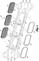
FIGURE 1 shows an isometric view of a representative embodiment of fitting assembly having a plurality of stiffening inserts according to the present disclosure; -
FIGURE 2 shows a partially exploded isometric view of the fitting assembly shown inFIGURE 1 ; -
FIGURE 3 shows an isometric view of a stiffening insert shown inFIGURE 1 ; -
FIGURE 4 shows a partial cross-sectional view of the stiffening insert shown inFIGURE 3 ; and -
FIGURE 5 shows a partial cross-sectional view of the fitting assembly shown inFIGURE 1 . - The detailed description set forth below in connection with the appended drawings, where like numerals reference like elements, are intended as a description of various embodiments of the present disclosure and are not intended to represent the only embodiments. Each embodiment described in this disclosure is provided merely as an example or illustration and should not be construed as precluding other embodiments. The illustrative examples provided herein are not intended to be exhaustive or to limit the disclosure to the precise forms disclosed.
- In the following description, specific details are set forth to provide a thorough understanding of exemplary embodiments of the present disclosure. It will be apparent to one skilled in the art, however, that the embodiments disclosed herein may be practiced without embodying all of the specific details. In some instances, well-known process steps have not been described in detail in order not to unnecessarily obscure various aspects of the present disclosure. Further, it will be appreciated that embodiments of the present disclosure may employ any combination of features described herein.
- The present disclosure may include references to directions, such as "forward," "rearward," "front," "rear," "upward," "downward," "top," "bottom," "right hand," "left hand," "lateral," "medial," "in," "out," "extended," etc. These references, and other similar references in the present disclosure, are only to assist in helping describe and to understand the particular embodiment and are not intended to limit the present disclosure to these directions or locations.
- The present disclosure may also reference quantities and numbers. Unless specifically stated, such quantities and numbers are not to be considered restrictive, but exemplary of the possible quantities or numbers associated with the present disclosure. Also in this regard, the present disclosure may use the term "plurality" to reference a quantity or number.
- Referring now to
FIGURES 1 and2 , a representative example of afitting assembly 100 that includes afitting 110 and a plurality ofstiffening inserts 150 is shown. In the illustrated embodiment, thefitting 110 is an elongate steel fitting formed withlugs 118 disposed on each end so that the fitting can be attached to surrounding structure bypins 130. A plurality ofpockets 120 is formed in thefitting 110 such that the pockets define portions of anupper rail 112, alower rail 114, andstiffening beams 116 that extend from the upper rail to the lower rail. - The bottom of each pocket defines one side of a
web 122. In the illustrated embodiment,second pocket 120 is formed on the opposite side of thefitting 110 such that the second pocket is symmetrical to, i.e., a mirror image of, the first pocket and defines a second side of theweb 122. In this manner theweb 122 is centrally positioned between the sides of the fitting; however, it will be appreciated that the position of the web, as well as the shape and depth of the pockets may vary within the scope of the present disclosure. Further, embodiments are contemplated in which corresponding pockets defining first and second surfaces of the web are not symmetrical but instead have different shapes and/or depths. - A
cutout 124 is formed in eachweb 122 such that the web extends only part way across the bottom of the pocket. In this regard, theweb 122 acts as a flange extending inwardly from the walls of thepocket 120, wherein the contour of thecutout 124 defines the end of the flange. - The disclosed
fitting 110 is suitable for use as a drag brace for an aircraft landing gear assembly; however, it will be appreciated that the disclosedstiffening inserts 150 are not limited to use with such fittings or to fittings utilized for aircraft. In this regard, the fitting may be formed from any suitable material, including titanium, aluminum, or any other suitable metallic or non-metallic material. In addition, the fitting may by machining, forging, casting, 3-D printing, or any suitable manufacturing process or combination of processes. It will further be appreciated that the shape of the fitting, including the number, shape, and size of pockets and internal cutouts, the inclusion or absence of mounting lugs or other attachment features, and any other features of the fitting may vary. That is, the disclosedstiffening inserts 150 can be utilized with a variety of different types of fittings that are utilized in any number of different assemblies having a variety of functions. - Referring now to
FIGURES 3 and4 , thestiffening insert 150 includes alattice 152 and acoupler 160 configured to couple the lattice to thefitting 110. In the illustrated embodiment, the lattice is a honeycomb structure, which is known to be lightweight and capable of withstanding high compressive via shear loads generated through the beam-column effect on the brace structure. In this regard, the honeycomb structure is capable of distributing a load by passing the load through the walls of the honeycomb. The honeycomb structure is configured to have a thickness, i.e., cell depth, that prevents the cell walls from buckling under experienced compressive loads. Further, the thickness of the honeycomb walls is configured so that stiffeninginsert 150 has the strength and stiffness required by the operating conditions of the fitting 110. - The disclosed
lattice 152 if formed from a polymeric material, such as polyetherimide (PEI). PEI is particularly suitable because it has relatively high strength and stiffness properties and can be formed using additive manufacturing techniques. In this regard, the compressive strength of PEI generally ranges from 152 MPa (22 ksi) to 221 MPa (32 ksi), and the compressive elastic modulus of PEI approximately 3309 MPa (480 ksi). The use of additive manufacturing techniques reduces manufacturing costs, while allowing a for a complex honeycomb design. The stiffening insert can be printed quickly and without significant machine preparation, which offers flexibility in the design and allows the part to be produced on an as-needed basis. - While the disclosed
lattice 152 is formed of PEI using additive manufacturing, the use of alternative configurations, materials, and manufacturing techniques is contemplated and should be considered within the scope of the present disclosure. In this regard, the lattice may be formed from other suitable materials, such as other suitable polymers, metals, and the like, or combinations thereof. Moreover, other manufacturing techniques suitable to the materials and configuration of thelattice 152 may be employed. In addition, thelattice 152 is not limited to a honeycomb having hexagonal cells, but can include cells of any number if shapes, such as round, triangular, square, octagonal, etc., or combinations thereof. - For embodiments in which the
lattice 152 is formed from a polymeric material, Fused Deposition Modeling (FDM), which involves layering material to form a solid, can be used. FDM is considered to be a superior method for producing high strength plastic parts. The only significant drawback is the layered surface finish it produces, which in turn limits its strength in the z-direction. However, this is generally not be an issue with the disclosed lattice, as the loading tends to be purely longitudinal (x and y directions). - For embodiments in which the
lattice 152 is formed from a metallic material, Electron Beam Additive Manufacturing (EBAM) can be used. For this method, metal wire or powder is heated using an electron beam and welded together to form a part. Although the higher density of the metallic material results in a weigh increase for comparable lattices, the metallic material also provides higher strength. - Still referring to
FIGURES 3 and4 , thecoupler 160 is configured to secure thelattice 152 to theweb 122 of apocket 120. Thecoupler 160 includes afirst coupler portion 162 surround the perimeter of thelattice 150. In the illustrated embodiment, thelattice 150 has a generally rectangular exterior shape that corresponds to the counter of thecutout 124 in theweb 122. Thefirst coupler portion 162 extends around the exterior perimeter of thelattice 150 and is sized and configured to engage theweb 122. - As best shown in the cross-sectional view of
FIGURE 4 , thefirst coupler portion 162 includes aninner surface 164 secured to thelattice 152. In the illustrated embodiment, thefirst coupler portion 162 is integrally formed with thelattice 150; however, it will be appreciated that thefirst coupler portion 162 may be formed separately from and/or from a different material or the same material than the lattice. For embodiments in which thefirst coupler portion 162 is manufactured separate from thelattice 150, the first coupler portion is secured to the lattice using mechanical fasteners, adhesives, welding, mating geometry, or any other suitable method or combination of methods. - Still referring to
FIGURE 4 , thefirst coupler portion 162 includes a retainingsurface 164 sized and configured to engage one side of theweb 122. Thefirst coupler portion 162 also includes first and second engagement surfaces 166 and 168 sized and configured to engage correspondingsurfaces second coupler portion 180, described below. The body of thefirst coupler portion 162 preferably has a roundedouter surface 170 and a plurality ofcavities 174 formed therein to decrease weight. - The
second coupler portion 180 includes a retainingsurface 184 that is generally parallel to and offset from the retainingsurface 164 of thefirst coupler portion 162 when thestiffening insert 150 is installed on the fitting 110. Thesecond coupler portion 180 also includes first and second interface surfaces 186 and 188 sized and configured to engage the first and second engagement surfaces 186 and 188, respectively, of thefirst coupler portion 162. Similar to thefirst coupler portion 162, thesecond coupler portion 180 preferably has a roundedouter surface 190 and a plurality ofcavities 194 formed therein to decrease weight. Aprotrusion 182 extends from thesecond retaining surface 184 to provide a transition between the first andsecond coupler portions stiffening insert 150 is coupled to the fitting 110. - The
first coupler portion 162 is coupled to thesecond coupler portion 180 by a plurality offasteners 196 positioned around the length of thecoupler 160. In the illustrated embodiment, eachfastener 196 extends through acounter-bored hold 192 formed in thesecond coupler portion 180 and threadedly engages a corresponding threadedhole 172 formed in thefirst coupler portion 162. When the first andsecond coupler portions first coupler portion 162 engage the first and second engagement surfaces 186 and 188, respectively, of thesecond coupler portion 180 to position the first and second coupler portions relative to each other. Further, when the first andsecond coupler portions web 122, thereby securing thestiffening insert 150 to the fitting 110. - The two-
piece coupler 160 of the disclosed embodiment is exemplary only and should not be considered limiting. In this regard, alternate embodiments are contemplated wherein the number, shape, configuration, etc. of the coupler components varies. Further, the present disclosure is not limited to the use of a particular number or type of fasteners to secure the lattice to the fitting. In this regard, the present disclosure contemplates the use of any number of mounting configurations that are suitable (1) to secure the lattice to the fitting and (2) transfer bending loads from the fitting into the lattice, and such alternate embodiments should be considered within the scope of the present disclosure. - Referring now to
FIGURES 4 and5 , to install thestiffening insert 150 in the fitting 110, thelattice 152 is positioned within thecutout 124 of theweb 122 so that the retainingsurface 164 of thefirst coupler portion 162 engages one side of the web. Thesecond coupler portion 180 is positioned so that the first and second engagement surfaces 186 and 188 of thesecond coupler portion 180 engage the first and second engagement surfaces 166 and 168, respectively, of thefirst coupler portion 162. With the first andsecond coupler portions surface 184 of thesecond coupler portion 180 engages a second side of theweb 122 so that the web is retained between the retainingsurfaces second coupler portions fasteners 196, thereby securing thestiffening insert 150 to the fitting. - The engagement of the stiffing
insert 150 with the fitting 110 is sufficient for the stiffening insert to resist deformation of the fitting 110. To the extent that the fitting 110 does deform, the deformation increases the contact force at certain regions around thecoupler 160. This force is then distributed through thelattice 152 and reacted by the fitting around thecutout 124 in theweb 122.
Claims (11)
- A fitting assembly (100) suitable for use as a drag brace for an aircraft landing gear assembly, comprising:
a fitting (110), which comprises a pocket (120) having a web (122) extending inward from a perimeter of the pocket, the web having an aperture defining an inner edge; characterized in that the fitting assembly further comprises a stiffening insert (150), comprising:(i) a lattice (152) ; and(ii) a coupler (160) configured to engage at least a portion of the web, the coupler coupling the lattice to the web. - The fitting assembly (100) of Claim 1, the coupler (160) comprising:(a) a first coupler portion (162) secured to the lattice (152), the first coupler portion having a first retaining surface (164); and(b) a second coupler portion (180) having a second retaining surface (184); wherein the first and second retaining surfaces (164, 184) engage the web (122) to secure the stiffening insert (150) to the web.
- The fitting assembly (100) of Claim 2, wherein the first coupler portion (162) is releasably coupled to the second coupler portion (180).
- The fitting assembly (100) of Claim 2, wherein the first retaining surface (164) engages a first side of the web (122), and the second retaining surface (184) engages a second side of the web (122).
- The fitting assembly (100) of Claim 2, wherein the first coupler portion (162) extends along the inner edge of the aperture.
- The fitting assembly (100) of Claim 2, further comprising a plurality of fasteners (196) securing the first coupler portion (162) to the second coupler portion (180).
- The fitting assembly (100) of Claim 2, wherein the first coupler portion (162) is integrally formed with the lattice (152).
- The fitting assembly (100) of Claim 1, wherein the lattice (152) comprises a plurality of hexagonal cells.
- The fitting assembly (100) of Claim 2, wherein the lattice (152) comprises a polymeric material.
- The fitting assembly (100) of Claim 1, wherein in use the coupler (160) transfers bending loads from the fitting (110) into the lattice (152).
- The fitting assembly (100) of Claim 2, wherein the first coupler portion (162) forms an endless loop surrounding a perimeter of the lattice (152).
Applications Claiming Priority (1)
| Application Number | Priority Date | Filing Date | Title |
|---|---|---|---|
| US15/782,631 US10301824B2 (en) | 2017-10-12 | 2017-10-12 | Lattice stiffener |
Publications (2)
| Publication Number | Publication Date |
|---|---|
| EP3470330A1 EP3470330A1 (en) | 2019-04-17 |
| EP3470330B1 true EP3470330B1 (en) | 2021-01-06 |
Family
ID=63840745
Family Applications (1)
| Application Number | Title | Priority Date | Filing Date |
|---|---|---|---|
| EP18200184.2A Active EP3470330B1 (en) | 2017-10-12 | 2018-10-12 | Lattice stiffener |
Country Status (3)
| Country | Link |
|---|---|
| US (1) | US10301824B2 (en) |
| EP (1) | EP3470330B1 (en) |
| CA (1) | CA3019729A1 (en) |
Family Cites Families (10)
| Publication number | Priority date | Publication date | Assignee | Title |
|---|---|---|---|---|
| US3020986A (en) | 1958-08-18 | 1962-02-13 | Gen Dynamics Corp | Composite structural panel |
| US3070198A (en) * | 1959-09-29 | 1962-12-25 | Haskell Boris | Honeycomb structures |
| US3532308A (en) * | 1968-06-04 | 1970-10-06 | Bendix Corp | Filament structure |
| US5839692A (en) | 1997-06-13 | 1998-11-24 | The Boeing Company | Splayable aircraft nose landing gear |
| US8376261B2 (en) | 2002-11-01 | 2013-02-19 | Airbus Uk Limited | Landing gear |
| US20050217191A1 (en) * | 2004-03-10 | 2005-10-06 | Davis John D | I-joist web hole insert |
| JP2009138451A (en) | 2007-12-07 | 2009-06-25 | Caterpillar Japan Ltd | Door panel |
| MX341498B (en) * | 2010-10-18 | 2016-08-22 | Honda Patents & Tech North America Llc | Quick release assembly for aircraft landing gear. |
| JP2015229390A (en) | 2014-06-04 | 2015-12-21 | 住友精密工業株式会社 | Landing gear of aircraft |
| US9920429B2 (en) | 2014-12-01 | 2018-03-20 | Raytheon Company | Method for manufacturing polymer-metal composite structural component |
-
2017
- 2017-10-12 US US15/782,631 patent/US10301824B2/en active Active
-
2018
- 2018-10-03 CA CA3019729A patent/CA3019729A1/en active Pending
- 2018-10-12 EP EP18200184.2A patent/EP3470330B1/en active Active
Non-Patent Citations (1)
| Title |
|---|
| None * |
Also Published As
| Publication number | Publication date |
|---|---|
| EP3470330A1 (en) | 2019-04-17 |
| US10301824B2 (en) | 2019-05-28 |
| US20190112811A1 (en) | 2019-04-18 |
| CA3019729A1 (en) | 2019-04-12 |
Similar Documents
| Publication | Publication Date | Title |
|---|---|---|
| EP2371704B1 (en) | Structure for the fuselage rear end | |
| US7841649B2 (en) | Vehicle body structure | |
| EP2772427B1 (en) | Vertically integrated stringers | |
| US9963172B2 (en) | Body structure of vehicle | |
| EP2444315B1 (en) | Metal fittings for engaging the vertical tailplane of an aircraft | |
| EP3350063B1 (en) | Automotive body shell | |
| DE102004004608B4 (en) | Vehicle body front structure | |
| US20180057062A1 (en) | Motor Vehicle | |
| US20120043772A1 (en) | Bumper structure | |
| EP3694778B1 (en) | Two-piece center frame assembly | |
| EP2032430B1 (en) | Aircraft fuselage structure and method for its production | |
| KR102183528B1 (en) | Vehicle end structure | |
| DE102015015519B4 (en) | Suspension structure | |
| US12221161B2 (en) | Long structural member and blank material | |
| CN106167085B (en) | For airframe pressure bulkhead and include the aircraft of this pressure bulkhead | |
| EP2572941B1 (en) | Crush box and vehicle bumper apparatus including the same | |
| CN111196343A (en) | Frame assembly for an aft section of an aircraft and aft section of an aircraft | |
| US10926812B2 (en) | Tailgate with mass and performance optimized reinforcement structure | |
| EP3470330A1 (en) | Lattice stiffener | |
| US20160375939A1 (en) | Vehicle and a cradle assembly for the vehicle | |
| US20200269924A1 (en) | Structure for vehicle | |
| US20130313391A1 (en) | Securing plate and aircraft structure | |
| EP2505490A1 (en) | Shock absorber | |
| EP3643600A1 (en) | Bulkhead joint assembly | |
| EP4282748A1 (en) | Stiffener integration in an isogrid structure |
Legal Events
| Date | Code | Title | Description |
|---|---|---|---|
| PUAI | Public reference made under article 153(3) epc to a published international application that has entered the european phase |
Free format text: ORIGINAL CODE: 0009012 |
|
| STAA | Information on the status of an ep patent application or granted ep patent |
Free format text: STATUS: THE APPLICATION HAS BEEN PUBLISHED |
|
| AK | Designated contracting states |
Kind code of ref document: A1 Designated state(s): AL AT BE BG CH CY CZ DE DK EE ES FI FR GB GR HR HU IE IS IT LI LT LU LV MC MK MT NL NO PL PT RO RS SE SI SK SM TR |
|
| AX | Request for extension of the european patent |
Extension state: BA ME |
|
| STAA | Information on the status of an ep patent application or granted ep patent |
Free format text: STATUS: REQUEST FOR EXAMINATION WAS MADE |
|
| 17P | Request for examination filed |
Effective date: 20191014 |
|
| RBV | Designated contracting states (corrected) |
Designated state(s): AL AT BE BG CH CY CZ DE DK EE ES FI FR GB GR HR HU IE IS IT LI LT LU LV MC MK MT NL NO PL PT RO RS SE SI SK SM TR |
|
| GRAP | Despatch of communication of intention to grant a patent |
Free format text: ORIGINAL CODE: EPIDOSNIGR1 |
|
| STAA | Information on the status of an ep patent application or granted ep patent |
Free format text: STATUS: GRANT OF PATENT IS INTENDED |
|
| INTG | Intention to grant announced |
Effective date: 20200804 |
|
| GRAS | Grant fee paid |
Free format text: ORIGINAL CODE: EPIDOSNIGR3 |
|
| GRAA | (expected) grant |
Free format text: ORIGINAL CODE: 0009210 |
|
| STAA | Information on the status of an ep patent application or granted ep patent |
Free format text: STATUS: THE PATENT HAS BEEN GRANTED |
|
| AK | Designated contracting states |
Kind code of ref document: B1 Designated state(s): AL AT BE BG CH CY CZ DE DK EE ES FI FR GB GR HR HU IE IS IT LI LT LU LV MC MK MT NL NO PL PT RO RS SE SI SK SM TR |
|
| REG | Reference to a national code |
Ref country code: GB Ref legal event code: FG4D |
|
| REG | Reference to a national code |
Ref country code: AT Ref legal event code: REF Ref document number: 1352074 Country of ref document: AT Kind code of ref document: T Effective date: 20210115 Ref country code: CH Ref legal event code: EP |
|
| REG | Reference to a national code |
Ref country code: DE Ref legal event code: R096 Ref document number: 602018011533 Country of ref document: DE |
|
| REG | Reference to a national code |
Ref country code: IE Ref legal event code: FG4D |
|
| REG | Reference to a national code |
Ref country code: NL Ref legal event code: MP Effective date: 20210106 |
|
| REG | Reference to a national code |
Ref country code: AT Ref legal event code: MK05 Ref document number: 1352074 Country of ref document: AT Kind code of ref document: T Effective date: 20210106 |
|
| REG | Reference to a national code |
Ref country code: LT Ref legal event code: MG9D |
|
| PG25 | Lapsed in a contracting state [announced via postgrant information from national office to epo] |
Ref country code: BG Free format text: LAPSE BECAUSE OF FAILURE TO SUBMIT A TRANSLATION OF THE DESCRIPTION OR TO PAY THE FEE WITHIN THE PRESCRIBED TIME-LIMIT Effective date: 20210406 Ref country code: GR Free format text: LAPSE BECAUSE OF FAILURE TO SUBMIT A TRANSLATION OF THE DESCRIPTION OR TO PAY THE FEE WITHIN THE PRESCRIBED TIME-LIMIT Effective date: 20210407 Ref country code: HR Free format text: LAPSE BECAUSE OF FAILURE TO SUBMIT A TRANSLATION OF THE DESCRIPTION OR TO PAY THE FEE WITHIN THE PRESCRIBED TIME-LIMIT Effective date: 20210106 Ref country code: FI Free format text: LAPSE BECAUSE OF FAILURE TO SUBMIT A TRANSLATION OF THE DESCRIPTION OR TO PAY THE FEE WITHIN THE PRESCRIBED TIME-LIMIT Effective date: 20210106 Ref country code: LT Free format text: LAPSE BECAUSE OF FAILURE TO SUBMIT A TRANSLATION OF THE DESCRIPTION OR TO PAY THE FEE WITHIN THE PRESCRIBED TIME-LIMIT Effective date: 20210106 Ref country code: PT Free format text: LAPSE BECAUSE OF FAILURE TO SUBMIT A TRANSLATION OF THE DESCRIPTION OR TO PAY THE FEE WITHIN THE PRESCRIBED TIME-LIMIT Effective date: 20210506 Ref country code: NO Free format text: LAPSE BECAUSE OF FAILURE TO SUBMIT A TRANSLATION OF THE DESCRIPTION OR TO PAY THE FEE WITHIN THE PRESCRIBED TIME-LIMIT Effective date: 20210406 |
|
| PG25 | Lapsed in a contracting state [announced via postgrant information from national office to epo] |
Ref country code: SE Free format text: LAPSE BECAUSE OF FAILURE TO SUBMIT A TRANSLATION OF THE DESCRIPTION OR TO PAY THE FEE WITHIN THE PRESCRIBED TIME-LIMIT Effective date: 20210106 Ref country code: AT Free format text: LAPSE BECAUSE OF FAILURE TO SUBMIT A TRANSLATION OF THE DESCRIPTION OR TO PAY THE FEE WITHIN THE PRESCRIBED TIME-LIMIT Effective date: 20210106 Ref country code: RS Free format text: LAPSE BECAUSE OF FAILURE TO SUBMIT A TRANSLATION OF THE DESCRIPTION OR TO PAY THE FEE WITHIN THE PRESCRIBED TIME-LIMIT Effective date: 20210106 Ref country code: PL Free format text: LAPSE BECAUSE OF FAILURE TO SUBMIT A TRANSLATION OF THE DESCRIPTION OR TO PAY THE FEE WITHIN THE PRESCRIBED TIME-LIMIT Effective date: 20210106 Ref country code: LV Free format text: LAPSE BECAUSE OF FAILURE TO SUBMIT A TRANSLATION OF THE DESCRIPTION OR TO PAY THE FEE WITHIN THE PRESCRIBED TIME-LIMIT Effective date: 20210106 |
|
| PG25 | Lapsed in a contracting state [announced via postgrant information from national office to epo] |
Ref country code: IS Free format text: LAPSE BECAUSE OF FAILURE TO SUBMIT A TRANSLATION OF THE DESCRIPTION OR TO PAY THE FEE WITHIN THE PRESCRIBED TIME-LIMIT Effective date: 20210506 |
|
| REG | Reference to a national code |
Ref country code: DE Ref legal event code: R097 Ref document number: 602018011533 Country of ref document: DE |
|
| PG25 | Lapsed in a contracting state [announced via postgrant information from national office to epo] |
Ref country code: EE Free format text: LAPSE BECAUSE OF FAILURE TO SUBMIT A TRANSLATION OF THE DESCRIPTION OR TO PAY THE FEE WITHIN THE PRESCRIBED TIME-LIMIT Effective date: 20210106 Ref country code: CZ Free format text: LAPSE BECAUSE OF FAILURE TO SUBMIT A TRANSLATION OF THE DESCRIPTION OR TO PAY THE FEE WITHIN THE PRESCRIBED TIME-LIMIT Effective date: 20210106 Ref country code: SM Free format text: LAPSE BECAUSE OF FAILURE TO SUBMIT A TRANSLATION OF THE DESCRIPTION OR TO PAY THE FEE WITHIN THE PRESCRIBED TIME-LIMIT Effective date: 20210106 |
|
| PLBE | No opposition filed within time limit |
Free format text: ORIGINAL CODE: 0009261 |
|
| STAA | Information on the status of an ep patent application or granted ep patent |
Free format text: STATUS: NO OPPOSITION FILED WITHIN TIME LIMIT |
|
| PG25 | Lapsed in a contracting state [announced via postgrant information from national office to epo] |
Ref country code: DK Free format text: LAPSE BECAUSE OF FAILURE TO SUBMIT A TRANSLATION OF THE DESCRIPTION OR TO PAY THE FEE WITHIN THE PRESCRIBED TIME-LIMIT Effective date: 20210106 Ref country code: SK Free format text: LAPSE BECAUSE OF FAILURE TO SUBMIT A TRANSLATION OF THE DESCRIPTION OR TO PAY THE FEE WITHIN THE PRESCRIBED TIME-LIMIT Effective date: 20210106 Ref country code: RO Free format text: LAPSE BECAUSE OF FAILURE TO SUBMIT A TRANSLATION OF THE DESCRIPTION OR TO PAY THE FEE WITHIN THE PRESCRIBED TIME-LIMIT Effective date: 20210106 |
|
| 26N | No opposition filed |
Effective date: 20211007 |
|
| PG25 | Lapsed in a contracting state [announced via postgrant information from national office to epo] |
Ref country code: ES Free format text: LAPSE BECAUSE OF FAILURE TO SUBMIT A TRANSLATION OF THE DESCRIPTION OR TO PAY THE FEE WITHIN THE PRESCRIBED TIME-LIMIT Effective date: 20210106 Ref country code: AL Free format text: LAPSE BECAUSE OF FAILURE TO SUBMIT A TRANSLATION OF THE DESCRIPTION OR TO PAY THE FEE WITHIN THE PRESCRIBED TIME-LIMIT Effective date: 20210106 |
|
| PG25 | Lapsed in a contracting state [announced via postgrant information from national office to epo] |
Ref country code: SI Free format text: LAPSE BECAUSE OF FAILURE TO SUBMIT A TRANSLATION OF THE DESCRIPTION OR TO PAY THE FEE WITHIN THE PRESCRIBED TIME-LIMIT Effective date: 20210106 |
|
| PG25 | Lapsed in a contracting state [announced via postgrant information from national office to epo] |
Ref country code: IT Free format text: LAPSE BECAUSE OF FAILURE TO SUBMIT A TRANSLATION OF THE DESCRIPTION OR TO PAY THE FEE WITHIN THE PRESCRIBED TIME-LIMIT Effective date: 20210106 |
|
| REG | Reference to a national code |
Ref country code: CH Ref legal event code: PL |
|
| PG25 | Lapsed in a contracting state [announced via postgrant information from national office to epo] |
Ref country code: IS Free format text: LAPSE BECAUSE OF FAILURE TO SUBMIT A TRANSLATION OF THE DESCRIPTION OR TO PAY THE FEE WITHIN THE PRESCRIBED TIME-LIMIT Effective date: 20210506 |
|
| REG | Reference to a national code |
Ref country code: BE Ref legal event code: MM Effective date: 20211031 |
|
| PG25 | Lapsed in a contracting state [announced via postgrant information from national office to epo] |
Ref country code: MC Free format text: LAPSE BECAUSE OF FAILURE TO SUBMIT A TRANSLATION OF THE DESCRIPTION OR TO PAY THE FEE WITHIN THE PRESCRIBED TIME-LIMIT Effective date: 20210106 |
|
| PG25 | Lapsed in a contracting state [announced via postgrant information from national office to epo] |
Ref country code: LU Free format text: LAPSE BECAUSE OF NON-PAYMENT OF DUE FEES Effective date: 20211012 Ref country code: BE Free format text: LAPSE BECAUSE OF NON-PAYMENT OF DUE FEES Effective date: 20211031 |
|
| PG25 | Lapsed in a contracting state [announced via postgrant information from national office to epo] |
Ref country code: LI Free format text: LAPSE BECAUSE OF NON-PAYMENT OF DUE FEES Effective date: 20211031 Ref country code: CH Free format text: LAPSE BECAUSE OF NON-PAYMENT OF DUE FEES Effective date: 20211031 |
|
| PG25 | Lapsed in a contracting state [announced via postgrant information from national office to epo] |
Ref country code: IE Free format text: LAPSE BECAUSE OF NON-PAYMENT OF DUE FEES Effective date: 20211012 |
|
| PG25 | Lapsed in a contracting state [announced via postgrant information from national office to epo] |
Ref country code: NL Free format text: LAPSE BECAUSE OF NON-PAYMENT OF DUE FEES Effective date: 20210206 Ref country code: CY Free format text: LAPSE BECAUSE OF FAILURE TO SUBMIT A TRANSLATION OF THE DESCRIPTION OR TO PAY THE FEE WITHIN THE PRESCRIBED TIME-LIMIT Effective date: 20210106 |
|
| PG25 | Lapsed in a contracting state [announced via postgrant information from national office to epo] |
Ref country code: HU Free format text: LAPSE BECAUSE OF FAILURE TO SUBMIT A TRANSLATION OF THE DESCRIPTION OR TO PAY THE FEE WITHIN THE PRESCRIBED TIME-LIMIT; INVALID AB INITIO Effective date: 20181012 |
|
| PG25 | Lapsed in a contracting state [announced via postgrant information from national office to epo] |
Ref country code: MK Free format text: LAPSE BECAUSE OF FAILURE TO SUBMIT A TRANSLATION OF THE DESCRIPTION OR TO PAY THE FEE WITHIN THE PRESCRIBED TIME-LIMIT Effective date: 20210106 |
|
| PG25 | Lapsed in a contracting state [announced via postgrant information from national office to epo] |
Ref country code: MT Free format text: LAPSE BECAUSE OF FAILURE TO SUBMIT A TRANSLATION OF THE DESCRIPTION OR TO PAY THE FEE WITHIN THE PRESCRIBED TIME-LIMIT Effective date: 20210106 |
|
| PG25 | Lapsed in a contracting state [announced via postgrant information from national office to epo] |
Ref country code: TR Free format text: LAPSE BECAUSE OF FAILURE TO SUBMIT A TRANSLATION OF THE DESCRIPTION OR TO PAY THE FEE WITHIN THE PRESCRIBED TIME-LIMIT Effective date: 20210106 |
|
| PGFP | Annual fee paid to national office [announced via postgrant information from national office to epo] |
Ref country code: DE Payment date: 20251020 Year of fee payment: 8 |
|
| PGFP | Annual fee paid to national office [announced via postgrant information from national office to epo] |
Ref country code: GB Payment date: 20251029 Year of fee payment: 8 |
|
| PGFP | Annual fee paid to national office [announced via postgrant information from national office to epo] |
Ref country code: FR Payment date: 20251024 Year of fee payment: 8 |