EP3470259A2 - Système d'accumulateurs d'énergie doté d'une pluralité d'accumulateurs d'énergie couplés en parallèle et procédé de fonctionnement d'un système d'accumulateurs d'énergie - Google Patents
Système d'accumulateurs d'énergie doté d'une pluralité d'accumulateurs d'énergie couplés en parallèle et procédé de fonctionnement d'un système d'accumulateurs d'énergie Download PDFInfo
- Publication number
- EP3470259A2 EP3470259A2 EP18194459.6A EP18194459A EP3470259A2 EP 3470259 A2 EP3470259 A2 EP 3470259A2 EP 18194459 A EP18194459 A EP 18194459A EP 3470259 A2 EP3470259 A2 EP 3470259A2
- Authority
- EP
- European Patent Office
- Prior art keywords
- energy storage
- charge
- energy
- state
- discharge
- Prior art date
- Legal status (The legal status is an assumption and is not a legal conclusion. Google has not performed a legal analysis and makes no representation as to the accuracy of the status listed.)
- Granted
Links
- 238000004146 energy storage Methods 0.000 title claims abstract description 388
- 238000000034 method Methods 0.000 title claims abstract description 28
- 230000006870 function Effects 0.000 claims description 17
- 230000008569 process Effects 0.000 claims description 15
- 230000004044 response Effects 0.000 claims description 4
- 238000000926 separation method Methods 0.000 claims description 2
- 125000004122 cyclic group Chemical group 0.000 abstract description 9
- 230000032683 aging Effects 0.000 abstract description 6
- 230000001419 dependent effect Effects 0.000 abstract description 3
- 210000004027 cell Anatomy 0.000 description 37
- 230000006854 communication Effects 0.000 description 8
- 238000004891 communication Methods 0.000 description 8
- 230000008901 benefit Effects 0.000 description 7
- 239000000203 mixture Substances 0.000 description 7
- 230000008859 change Effects 0.000 description 6
- 238000010586 diagram Methods 0.000 description 6
- 238000007599 discharging Methods 0.000 description 6
- 230000003679 aging effect Effects 0.000 description 3
- 239000004020 conductor Substances 0.000 description 2
- 238000013461 design Methods 0.000 description 2
- 238000011161 development Methods 0.000 description 2
- 230000018109 developmental process Effects 0.000 description 2
- 230000000694 effects Effects 0.000 description 2
- 238000005259 measurement Methods 0.000 description 2
- 230000009467 reduction Effects 0.000 description 2
- 238000012360 testing method Methods 0.000 description 2
- 238000012935 Averaging Methods 0.000 description 1
- XAGFODPZIPBFFR-UHFFFAOYSA-N aluminium Chemical compound [Al] XAGFODPZIPBFFR-UHFFFAOYSA-N 0.000 description 1
- 229910052782 aluminium Inorganic materials 0.000 description 1
- 230000007175 bidirectional communication Effects 0.000 description 1
- 239000002131 composite material Substances 0.000 description 1
- 238000010276 construction Methods 0.000 description 1
- 230000008878 coupling Effects 0.000 description 1
- 238000010168 coupling process Methods 0.000 description 1
- 238000005859 coupling reaction Methods 0.000 description 1
- 230000003247 decreasing effect Effects 0.000 description 1
- 230000010354 integration Effects 0.000 description 1
- 238000002955 isolation Methods 0.000 description 1
- 239000000463 material Substances 0.000 description 1
- 238000012986 modification Methods 0.000 description 1
- 230000004048 modification Effects 0.000 description 1
- 238000012544 monitoring process Methods 0.000 description 1
- 239000007858 starting material Substances 0.000 description 1
- 210000000352 storage cell Anatomy 0.000 description 1
Images


Classifications
-
- B—PERFORMING OPERATIONS; TRANSPORTING
- B60—VEHICLES IN GENERAL
- B60L—PROPULSION OF ELECTRICALLY-PROPELLED VEHICLES; SUPPLYING ELECTRIC POWER FOR AUXILIARY EQUIPMENT OF ELECTRICALLY-PROPELLED VEHICLES; ELECTRODYNAMIC BRAKE SYSTEMS FOR VEHICLES IN GENERAL; MAGNETIC SUSPENSION OR LEVITATION FOR VEHICLES; MONITORING OPERATING VARIABLES OF ELECTRICALLY-PROPELLED VEHICLES; ELECTRIC SAFETY DEVICES FOR ELECTRICALLY-PROPELLED VEHICLES
- B60L58/00—Methods or circuit arrangements for monitoring or controlling batteries or fuel cells, specially adapted for electric vehicles
- B60L58/10—Methods or circuit arrangements for monitoring or controlling batteries or fuel cells, specially adapted for electric vehicles for monitoring or controlling batteries
- B60L58/18—Methods or circuit arrangements for monitoring or controlling batteries or fuel cells, specially adapted for electric vehicles for monitoring or controlling batteries of two or more battery modules
- B60L58/21—Methods or circuit arrangements for monitoring or controlling batteries or fuel cells, specially adapted for electric vehicles for monitoring or controlling batteries of two or more battery modules having the same nominal voltage
-
- B—PERFORMING OPERATIONS; TRANSPORTING
- B60—VEHICLES IN GENERAL
- B60L—PROPULSION OF ELECTRICALLY-PROPELLED VEHICLES; SUPPLYING ELECTRIC POWER FOR AUXILIARY EQUIPMENT OF ELECTRICALLY-PROPELLED VEHICLES; ELECTRODYNAMIC BRAKE SYSTEMS FOR VEHICLES IN GENERAL; MAGNETIC SUSPENSION OR LEVITATION FOR VEHICLES; MONITORING OPERATING VARIABLES OF ELECTRICALLY-PROPELLED VEHICLES; ELECTRIC SAFETY DEVICES FOR ELECTRICALLY-PROPELLED VEHICLES
- B60L58/00—Methods or circuit arrangements for monitoring or controlling batteries or fuel cells, specially adapted for electric vehicles
- B60L58/10—Methods or circuit arrangements for monitoring or controlling batteries or fuel cells, specially adapted for electric vehicles for monitoring or controlling batteries
- B60L58/18—Methods or circuit arrangements for monitoring or controlling batteries or fuel cells, specially adapted for electric vehicles for monitoring or controlling batteries of two or more battery modules
-
- H—ELECTRICITY
- H02—GENERATION; CONVERSION OR DISTRIBUTION OF ELECTRIC POWER
- H02J—CIRCUIT ARRANGEMENTS OR SYSTEMS FOR SUPPLYING OR DISTRIBUTING ELECTRIC POWER; SYSTEMS FOR STORING ELECTRIC ENERGY
- H02J7/00—Circuit arrangements for charging or depolarising batteries or for supplying loads from batteries
- H02J7/0013—Circuit arrangements for charging or depolarising batteries or for supplying loads from batteries acting upon several batteries simultaneously or sequentially
- H02J7/0025—Sequential battery discharge in systems with a plurality of batteries
-
- H—ELECTRICITY
- H02—GENERATION; CONVERSION OR DISTRIBUTION OF ELECTRIC POWER
- H02J—CIRCUIT ARRANGEMENTS OR SYSTEMS FOR SUPPLYING OR DISTRIBUTING ELECTRIC POWER; SYSTEMS FOR STORING ELECTRIC ENERGY
- H02J7/00—Circuit arrangements for charging or depolarising batteries or for supplying loads from batteries
- H02J7/0063—Circuit arrangements for charging or depolarising batteries or for supplying loads from batteries with circuits adapted for supplying loads from the battery
-
- H—ELECTRICITY
- H02—GENERATION; CONVERSION OR DISTRIBUTION OF ELECTRIC POWER
- H02J—CIRCUIT ARRANGEMENTS OR SYSTEMS FOR SUPPLYING OR DISTRIBUTING ELECTRIC POWER; SYSTEMS FOR STORING ELECTRIC ENERGY
- H02J7/00—Circuit arrangements for charging or depolarising batteries or for supplying loads from batteries
- H02J7/007—Regulation of charging or discharging current or voltage
- H02J7/00712—Regulation of charging or discharging current or voltage the cycle being controlled or terminated in response to electric parameters
-
- H—ELECTRICITY
- H02—GENERATION; CONVERSION OR DISTRIBUTION OF ELECTRIC POWER
- H02J—CIRCUIT ARRANGEMENTS OR SYSTEMS FOR SUPPLYING OR DISTRIBUTING ELECTRIC POWER; SYSTEMS FOR STORING ELECTRIC ENERGY
- H02J2310/00—The network for supplying or distributing electric power characterised by its spatial reach or by the load
- H02J2310/40—The network being an on-board power network, i.e. within a vehicle
- H02J2310/48—The network being an on-board power network, i.e. within a vehicle for electric vehicles [EV] or hybrid vehicles [HEV]
-
- Y—GENERAL TAGGING OF NEW TECHNOLOGICAL DEVELOPMENTS; GENERAL TAGGING OF CROSS-SECTIONAL TECHNOLOGIES SPANNING OVER SEVERAL SECTIONS OF THE IPC; TECHNICAL SUBJECTS COVERED BY FORMER USPC CROSS-REFERENCE ART COLLECTIONS [XRACs] AND DIGESTS
- Y02—TECHNOLOGIES OR APPLICATIONS FOR MITIGATION OR ADAPTATION AGAINST CLIMATE CHANGE
- Y02T—CLIMATE CHANGE MITIGATION TECHNOLOGIES RELATED TO TRANSPORTATION
- Y02T10/00—Road transport of goods or passengers
- Y02T10/60—Other road transportation technologies with climate change mitigation effect
- Y02T10/70—Energy storage systems for electromobility, e.g. batteries
Definitions
- the invention relates to an energy storage system having a plurality of energy stores connected in parallel and a method for operating such an energy storage system.
- the energy storage system may be a traction energy storage system, in particular for a vehicle, for example for a commercial vehicle.
- a technique for variably interconnecting, for example, connecting, energy stores in an energy storage system during unloading is described.
- Electric energy storage devices in particular traction batteries or high-voltage batteries of mild hybrid, hybrid or electric vehicles, are subject to various aging effects and should be designed with regard to the aging effects on a planned service life, preferably the planned product life of the motor vehicle. Due to a very long operating time of the batteries, even with low currents, high cyclic aging occurs.
- a further or alternative object of the invention is to provide an energy storage system for storing and emitting electrical energy, in particular electrical traction energy, which has the lowest possible cyclic (load-dependent) aging.
- the invention is based on the technical realization that it is advantageous for life reasons to operate in such operating situations, a lower number of energy storage devices of the energy storage system with higher current load in contrast to an operation of the energy storage system, in which all or a large number of energy storage with be discharged at a lower current load.
- a lower number of energy storage devices of the energy storage system with higher current load in contrast to an operation of the energy storage system, in which all or a large number of energy storage with be discharged at a lower current load.
- an energy storage system is provided with a plurality of energy stores connected in parallel.
- the energy storage system may be a traction energy storage system for a vehicle, in particular for a utility vehicle.
- the energy storage system may further be a stationary energy storage system.
- the energy storage system comprises a plurality of electrical energy stores, each of the energy stores electrically connected cell modules, the z. B. are connected via busbars, a contactor, an energy storage high-voltage interface and the contactor controlling energy storage control includes.
- Each of the cell modules comprises a plurality of memory cells, and preferably a cell module controller.
- the contactor is designed to connect the cell modules of the energy storage with the energy storage high voltage interface of the respective energy storage according to the energy storage control in a closed position of the contactor and to disconnect in an open position of the contactor.
- the contactor may be configured to connect busbars of the energy storage with the energy storage high-voltage interface of the respective energy storage according to the energy storage control in a closed position of the contactor and to disconnect in an open position of the contactor.
- the energy storage can also include multiple switch support.
- the contactor or the contactors are designed to connect the busbars of the energy storage with the high-voltage interface in a closed position of the contactor or the contactors and to disconnect in an open position of the contactor or the contactors.
- An energy store may be referred to as "disconnected" when its contactor is in the open position.
- Each of the energy storage devices can be arranged in a separate housing.
- the energy storage high-voltage interfaces of the energy storage are connected in parallel.
- the energy storage system is thus constructed modularly from individual, parallel-connected energy storage devices.
- the first discharge mode is to provide discharge power, for example, to provide electrical traction energy for vehicle driving if the energy storage system is a traction energy storage system of a vehicle.
- This unloading mode is referred to as a first unloading mode to better distinguish this unloading mode from a further unloading mode (second unloading mode) to be described later.
- the first discharge mode thus repeated switching to a discharge group, which is then composed of other energy storage, by disconnecting the last connected energy storage and switching on at least one energy storage, which at this time of the non-energized energy storage has the highest state of charge.
- electrical energy electrical, for example, traction energy
- the first discharge mode is only provided by a subset of energy stores, namely the energy stores that are currently assigned to and connected to the discharge group and have the highest charge state at the time of switch-on.
- the composition of the unloading group is set and changed each time the steps are repeated, so that on the one hand only a subset of energy stores is switched on and unloaded and on the other hand the state of charge of all or at least most of the energy stores over time gradually reduced.
- a discharge process according to the first discharge mode thus offers the particular advantage that the required electrical power is represented by a subset of the parallel-connected energy storage, which must be operated according to higher power than an operation in which all energy storage are discharged with a correspondingly smaller current. As already mentioned above, this is to improve the life or to slow down the cyclic aging of the energy storage advantage. By reducing the cyclic loading time of each individual system, this leads to an increase in the overall service life of the energy storage system.
- a particular advantage of the proposed first discharge mode is further that this can be avoided without the use of a DC / DC converter for coupling the energy storage to the power supply switching interruptions to change the switched energy storage during driving.
- the reason is that the respectively connected energy storage of the first discharging group are always discharged only until the state of charge has fallen to the value which is smaller by a predetermined value than a state of charge of the non-connected energy storage, the non-energized energy storage highest charge state.
- This energy storage is then optionally set with other previously not energized energy storage, the state of charge is higher than the current state of charge of the energy storage of the previous first unloading group, as a new first discharge and switched.
- this newly defined first discharge group is likewise again discharged until its state of charge (eg the average charge state of the first discharge group) has dropped to a state of charge which is smaller than a charge state of the non-connected energy store by the predetermined value, which has the highest state of charge of the non-connected energy storage, etc.
- this discharge mode is thus a sequential operation of the individual energy storage or individual groups of energy storage, in which the charge states of the individual energy storage cascade-like and temporally gradually decrease.
- the first discharge mode is performed only if a power request to the energy storage system is less than a predetermined power threshold selected to provide power requirements below that power threshold only from a subset of the energy stores of the energy storage system.
- the discharge group may comprise only one or more energy stores. Furthermore, a minimum number and / or a maximum number can be specified for the number of energy stores in the discharge group for the first discharge mode.
- the setting of the first discharge group may include: determining the N energy stores having the N highest values of the determined states of charge, where N is a predetermined natural number or a natural number determined depending on the determined states of charge and / or in response to a power request to the energy storage system ⁇ 1, and setting the determined N energy storage as a discharge group. N is smaller than the total number of energy stores of the energy storage system.
- the number N can be determined as a function of a power demand on the energy storage system, in particular in such a way that N specifies the smallest number of energy stores with which the current power requirement can be provided as discharge power.
- the first discharge group can only contain energy storage with the same state of charge, i. that is, those having the highest state of charge at the time of determining the (composition of) the first discharge group.
- the first discharge group contain those energy stores whose state of charge does not differ by more than a predetermined difference from the highest state of charge of all energy stores.
- the number of energy stores in the discharge group can be limited to the number N, as described above.
- system controller of the energy storage system may be configured to only parallel to each other energy storage whose difference in the state of charge or the open circuit voltage is less than a certain limit to reduce equalization currents between these energy storage as possible.
- a preferred embodiment provides that, after the state of charge of the connected energy storage of the first discharge has fallen to the value which is smaller by a predetermined value than a state of charge of that energy storage, which has the highest charge state of the non-energized energy storage, switching according to the first unloading on a newly defined unloading group with at least this energy storage by disconnecting the last connected energy storage and the connection of the newly defined unloading takes place only when a predetermined Umschaltvorausario.
- the predetermined Umschaltvorausus additionally be met for switching. This offers the advantage that switching can only take place when suitable operating situations or driving situations are present in which possibly disturbing switching effects (eg interruption of the electrical drive power) have as little effect as possible.
- the predetermined Umschaltvorausario be met if the vehicle has come to a halt, z. B. during breaks and / or if a value of a size that is a measure of the current power demand or driving load, falls below a predetermined load threshold, d. H. at low load while driving.
- a size can z. B. be the driver's desired torque or the torque input for the drive motor. In these operating or driving situations, the train interruptions are not present due to the switching or at least less disturbing.
- the system controller may be designed to perform the switching even if the switchover requirement is not fulfilled if the switchover requirement is not met after a predetermined period of time has elapsed after the charge state of the connected energy store has dropped to a value which by a predetermined difference is smaller than a state of charge of that energy storage, which has the highest charge state of the non-connected energy storage. As a result, excessive discharge of the currently energized energy storage can be avoided.
- a second discharge mode may be provided, in which alternating groups of energy stores are not alternately discharged as in the first discharge mode, but in which, starting from the energy store or the energy stores with the highest state of charge, is discharged first successively accumulated further energy storage for unloading according to their state of charge, d. H. be switched on.
- the charge states of energy stores can be adjusted in a targeted manner in order to form groups of energy stores, which are then, summarized as a first discharge group, suitable for carrying out the first discharge mode.
- the second discharge mode is also suitable for maximizing the range, especially when the charge states of all energy storage devices have decreased sufficiently.
- the addition of a further energy store, which has not yet been connected, to the second discharge group can take place when a state of charge of the energy store of the second discharge group (eg an average state of charge of the energy store of the second discharge group) reaches a state of charge of an energy store which has not yet been switched on or its state of charge does not differ by more than a predetermined value from the state of charge of a previously unconnected energy storage. In this way, high balancing currents can be avoided when connecting and charging states of different energy storage can be targeted.
- a state of charge of the energy store of the second discharge group eg an average state of charge of the energy store of the second discharge group
- system controller may be configured to selectively perform an unloading operation according to the first unloading mode or according to the second unloading mode.
- system control is designed to change from a discharge process according to the first discharge mode to a discharge process according to the second discharge mode if the state of charge of all energy storage devices is in each case less than a predetermined threshold value. In this case, all can then successively Energy storage successively "collected” according to their state of charge, ie switched on. This is advantageous for maximizing the range.
- the system controller may be configured to start a discharge process with a second discharge mode if and until a number of the energy stores having the highest state of charge reaches a predetermined minimum number, and to change to the first discharge mode upon reaching the minimum number.
- the minimum number can represent the number of energy stores that should form a discharge group in the first unloading mode. If only two energy stores are to be discharged simultaneously in the first discharge mode, but only one energy store has the current highest charge state, the energy store with the highest charge state can be brought to the state of charge of the energy store with the second highest charge state by means of the second discharge mode, which then subsequently together according to FIG discharged in the first discharge mode.
- connection of other previously not switched energy storage is carried out until all energy storage are switched in accordance with the state of charge.
- the invention further relates to a vehicle including a traction energy storage system as described in this document.
- the vehicle may be a land vehicle, a watercraft (eg a ship or submarine) or an aircraft.
- the vehicle may be a commercial vehicle (for example, a goods transport lorry and / or a passenger transport bus) or a passenger car.
- state of charge SOC
- OCV open-circuit voltage
- parameter group the or a measure of the state of charge of the energy storage indicates or from or from the state of charge can be derived.
- the cell module controllers can be configured to output measured values relating to the memory cells in the respective cell module, and the energy storage controllers can be designed to determine a memory state, in particular a state of charge of the energy store, depending on the measured values of the cell modules in the respective energy store.
- each energy storage controller may be configured to determine a cell charge state of each storage cell based on the respective cell states (eg, cell voltages (eg, by comparison with a stored curve or tabulated relation between open circuit voltage (also called open circuit voltage or OCV) and state of charge) ,
- each cell module controller can determine the cell charge states of its memory cells and output it as a cell state. From these cell charge states can, for. B.
- Each energy storage controller can be designed to output to the system controller a minimum and / or a maximum of the cell voltages of the memory cells in the respective energy store as well as the storage charge state.
- FIG. 1 shows a schematic block diagram of an energy storage system generally designated by reference numeral 100.
- this is a traction energy storage system (TES system) for a vehicle, for example a commercial vehicle.
- TES system traction energy storage system
- the TES system 100 comprises at least two energy stores 110.
- Each energy store 110 comprises in each case a plurality of cell modules 120 and an energy store controller 130.
- Each of the cell modules 120 includes a plurality of memory cells 122 and a cell module controller 124.
- Each cell module controller 124 acquires measurements relating to the respective associated memory cells 122.
- the cell module controller 124 detects a voltage and / or a temperature of the memory cells 122 in the respective cell module 120 is designed to read the measurements on an internal data bus 126 issue.
- the internal data bus 126 of the cell module 120 may be a serial bus, for example for a controller area network (CAN).
- Each of the energy storage controllers 130 is designed to receive the measured values from the cell modules 120 in the respective energy store 110.
- each energy storage controller 110 is connected to the respective internal data bus 126.
- Each of the energy storage controllers 130 is further configured to generate a signal depending on the measured values obtained. To output the signal or other signals, the energy storage controller 130 is connected to an external data bus 132.
- the external data bus 132 of the TES system 100 may be a serial bus, such as another CAN bus.
- the external data bus 132 may be designed exclusively for communication between the energy stores 110 (or their energy storage controllers 130).
- the energy storage devices 110 are each arranged in a separate housing 112.
- the internal data bus 126 extends within the respective housing 112.
- the external data bus 132 extends outside the housing 112.
- the TES system 100 further includes a system controller 140.
- the system controller 140 may be configured to receive signals from the energy storage controllers 130, generate a system signal based on the received signals, and output the system signal to a functional network 150 of the vehicle.
- the functional network 150 may include a low voltage electrical system and / or a bus system for communication between vehicle functions.
- the low voltage electrical system can provide a supply voltage of 24 volts.
- the external data bus 132 may be designed exclusively for communication between the energy stores 110 (or their energy storage controllers 130).
- the functional network 150 can be connected to the system controller 140 via its own interface and / or its own bus connection 202.
- a separate bus for example, a separate CAN bus
- vehicle communication which operates independently of the external data bus 132.
- the external data bus 132 (eg instead of the separate bus connection 202 or in addition thereto) may be connected to the functional network 150 (dashed arrow).
- the TES system 100 may include a unitary vehicle interface to the functional network 150 of the vehicle, which is independent of the number of energy storage devices 110 used and interconnected.
- the vehicle interface may be at a physical level (eg, with respect to connector and / or waveform) or a physical layer (eg, with respect to a communication protocol) independent of a variable composition of the energy storage 110 included in the TES system 100 his.
- the system controller 140 may be implemented in an energy storage 110, for example in one of the energy storage controllers 130. Alternatively or additionally, the system controller 140 may be implemented outside of the energy store 110, for example as a separate device in a separate housing or component of the functional network 150.
- An energy store 110 which performs the function of the system controller 140 is also referred to as a master energy store 110-. M denotes.
- the one or more energy storage devices 110 that do not perform the function of the system controller 140 are also referred to as slave energy storage devices 110-S. Corresponding designations apply to the respective energy storage controllers 130-M and 130-S.
- the system controller 140 may be configured to receive the signals from the energy storage controllers 130-S via the external data bus 132.
- the system signal may be output from the system controller 140 to the functional network 150 via a direct connection (eg, the bus 202) of the system controller 140 to the functional network 150.
- the system signal may be output to the functional network 150 via the external data bus 132.
- the functional network 150 is connected to the external data bus 132 (for example, directly or via a gateway).
- the memory cells 122 of a cell module 120 are connected together (for example in series).
- the connection terminals 127 resulting from the interconnection are connected via bus bars 128.
- the bus bars 128 may be made of aluminum or other conductive material.
- the poles resulting from the combination of the cell modules 120 of each energy storage device 110 form an energy storage high-voltage interface 114 (hereinafter: high-voltage interface).
- the high-voltage interfaces 114 may be connected in parallel or in series and may be connected or connectable to a power network 160 of the vehicle.
- the power network 160 may include a high voltage vehicle electrical system.
- a powertrain of the vehicle may be connected to the power network 160 for taking the energy stored in the TES system 100 and / or for charging the TES system 100, for example during a recuperative braking process.
- the powertrain may include a crankshaft starter generator or an electric machine as a primary drive (optionally connected via an inverter).
- the power network 160 may also be referred to as a traction network.
- the power network 160 may provide a voltage of at least 60 volts, for example between 540 volts and 738 volts. Alternatively or additionally, the power network 160 can be any high-voltage vehicle electrical system in the sense of vehicle construction.
- a topology of the power grid 160 and / or its components may demarcate the power grid 160 from a low-voltage grid (of, for example, 24 volts, in particular the low-voltage vehicle electrical system).
- the topology may be consistent with or adapted to a known vehicle topology for hybrid, plug-in or electric vehicles.
- the components may include an inverter (eg, the inverter or inverter) for travel drives, the TES system 100, one or more electrical machines, auxiliaries, and / or a wiring harness.
- each energy storage 110 at least one contactor 170 is arranged between the cell modules 120 and the power network 160.
- the contactor 170 is or the contactors 170 are controlled by the energy storage controller 130 in the same energy storage 110 via the control line shown by reference numeral 172 for selectively disconnecting the respective energy storage device 110 from the power network 160.
- the contactor 170 may be part of a contactor box that further monitors the electrical isolation of the bus bars 128 (eg, from a reference potential), measures the current flowing over the bus bars 128, and / or measures the voltage applied to the bus bars 128 (for example, FIG Open contactor open circuit voltage).
- the contactors 170 of the switched-on (and possibly functional) energy store 110 may be closed (closed position).
- the corresponding energy storage 110 can be isolated in the operating state of the TES system 100 from the composite of the TES system 100, for example in an inadmissible memory state or for measuring the open circuit voltage.
- the system controller 140 in an idle state of the TES system 100 cause the open position of the contactors 170 of all energy storage 110.
- a precharge contactor (or, in short, precharge contactor) and a precharge resistor connected in series with the precharge contactor may be installed in each energy store 110 in parallel with one of the contactors 170 (which may also be referred to as main contactors).
- the precharge resistor may be a PTC thermistor or PTC resistor.
- the energy storage controller 130 may close the precharge contactor. The energy storage controller 130 may cause the closed position of the contactors 170 as soon as a voltage difference across the precharge resistor falls below a threshold value.
- the system controller 140 is further configured for bidirectional communication with the functional network 150 of the vehicle.
- the system signals may be generated and output in response to a vehicle signal (from the functional network 150 of the vehicle).
- the vehicle signal may include a control instruction.
- the system controller 140 analyzes the control instruction for determining those energy stores 110 that are relevant for implementing the control instruction, and outputs a control signal to the energy storage controllers 130 of the relevant energy store 110.
- the TES system 100 can be scalably deployed at the level of the energy storage 110 due to the modular design.
- the energy storage devices 110 can be interconnected several times in parallel or serially.
- the TES system 100 can be configured for a vehicle-specific power and energy requirement. These requirements may depend on the degree of electrification of the powertrain of the vehicle. Furthermore, the power requirement may be determined by a transport performance of the vehicle, for example the utility vehicle, and the energy requirement by a range of the vehicle.
- the interconnection and / or the number of interconnected energy storage 110 can be changed in the operating state, for example controllable by the vehicle signal.
- the system controller 140 provides a uniform data interface to the vehicle regarding a physical interface and a communication protocol, which may be independent of the vehicle-specific configuration of the TES system 100.
- the multiple energy storage devices 110 may behave as a correspondingly large energy storage device due to communication via the system controller 140 to the vehicle. As a result, a vehicle-specific integration effort is minimized.
- FIG. 2 shows a schematic block diagram of a second embodiment of a TES system 100, whose features with the first embodiment of the FIG. 1 can be combined. Reference numerals that correspond to the other exemplary embodiments denote corresponding or identical features.
- the system controller 140 is disposed outside the housing 112 of the energy storage 110.
- the system controller 140 includes a first data interface 142 for on-vehicle communication.
- the first data interface 142 is connected to the functional network 150 and / or to a motor controller.
- the system controller 140 includes a second data interface 143, which is connected via the external data bus 132 with data interfaces 144 of the energy storage 110.
- the system controller 140 receives the signals of the individual energy stores 110 via the second data interface 143.
- the system signal is output via the first data interface 142.
- the high-voltage interfaces 114 of the individual energy storage 110 are connected in parallel and connected to the power network 160 and / or the inverter.
- a system high voltage interface 162 may be provided for energy exchange between the TES system 100 and the power network 160 of the vehicle.
- system current 204 The current / through the system high voltage interface 162 is referred to as system current 204.
- the uniform voltage U of the parallel circuit is applied to the system high-voltage interface 162 and is referred to as system voltage 206. Due to the parallel connection, the system current 204 may also be referred to as the total current of the TES system 100.
- a system contactor 164 controlled by the system controller 140 which may optionally be provided in addition, makes it possible to disconnect the system high-voltage interface 162 from the voltage.
- the system contactor 164 may be disposed in a high voltage distribution unit of the power network 160.
- the system contactor 164 may be controlled directly (eg, via the external data bus 132) or indirectly (eg, via a component of the functional network 150) by the system controller 140.
- the TES system 100 may also be implemented without a system contactor 164.
- the first data interface 142 is connected to a serial bus 202 of the vehicle functional network 150, for example a CAN bus independent of the TES system 100.
- FIG. 3 shows a schematic block diagram of a third embodiment of a TES system 100 for a vehicle.
- the third embodiment is different from second embodiment in that the function of the system controller 140 in an energy storage 110-M of the energy storage 110 is executed.
- the energy store 110-M comprises the first data interface 142.
- the energy store 110-M receives the signals of the other energy stores 110-S via a second data interface 144, which do not perform the function of the system controller 140.
- the first data interface 142 and the second data interface 144 are each connected in the energy store 110-M to the energy storage controller 130-M, which performs the function of the system controller 140.
- All energy storage devices 110-M and 110-S are preferably identical. Also, the energy storage devices 110-S may include a first data interface 142, which is unconnected outside the energy storage device 110-S. The second data interfaces 144 of all energy stores 110-M and 110-S are connected via the external data bus 132.
- the function of the system controller 140 is also implemented in each energy store controller 130-S of the energy store 110-S and not activated for execution (shown as a dashed function block in FIG. 3 ). By setting one or more parameters of the energy storage controller 130, the function of the system controller 140 may be selectively enabled and disabled for execution.
- the in the Figures 2 and 3 shown parallel connection of the three high-voltage interfaces 114 is exemplary. Depending on the requirements of the vehicle power network 160 (eg with regard to current, voltage, power and / or energy), a larger number of energy stores 110 and / or a different interconnection of the high-voltage interfaces 114 can be used. In particular, the high-voltage interfaces 114 can be connected in series within a respective group of energy stores 110, and the groups can be connected in parallel with one another.
- each energy storage 110 For interconnecting a subset of the energy stores 110, their (for example, at the respective high-voltage interfaces 114 implemented) contactors 170 (and the system contactor 164) can be closed.
- the voltages at the high-voltage interfaces 114 of the interconnected energy stores 110 are uniform due to the parallel connection of the energy storage 110.
- charging or discharging currents flow through the system high-voltage interface 162.
- the current flowing through the system high-voltage interface 162 is not distributed (at least in general) in equal parts to the high-voltage interfaces 114 of the individual energy stores 110.
- the storage state of each energy storage 110 may include electrochemical state variables (eg state of charge, state of aging or storage capacity) and / or electrical quantities (eg current, open circuit voltage, internal resistance).
- each energy storage 110 may describe its storage capability as the charge that can be taken out in the fully charged state (eg, the time integral of the discharge current from the initial voltage to the final voltage).
- the state of charge (also referred to as "state of charge” or SoC) of each energy store 110 is the proportion of the still removable charge in the storage capacity.
- the functional relationship between the (eg, relaxed) open circuit voltage (OCV) at the high voltage interface 114 and the state of charge of the energy store 110 is the discharge curve.
- OCV open circuit voltage
- the discharge curve can be tabulated and / or updated by integrating the current in the operating state.
- the individual energy stores 110 in the TES system 100 may differ in their charge states. Therefore, (for example, in or after an operating state of the TES system 100, when the vehicle is turned off and / or a terminal of the vehicle ignition is at a reference potential), the energy storage 110 may be present in different states of charge.
- FIGS. 4 to 7 show flowcharts that describe different embodiments for the variable interconnection, for example, to connect, energy storage in a traction energy storage system during unloading.
- the described controls or methods can be used in any of the FIGS. 1 to 3 shown traction energy storage systems 100 are implemented.
- FIG. 4 1 shows a flow chart illustrating a first discharge mode according to an exemplary embodiment of the invention, in which alternately different groups of energy stores 110 are switched on in order to provide electrical energy from the parallel-connected TES system 100.
- the first discharge mode is further exemplified in FIG FIG. 8 illustrated, to which reference is also made below.
- the first discharge mode 400 in this case, in particular, a repeated switching to different energy stores takes place, which are respectively discharged.
- FIG. 8 this is illustrated by a highly simplified example with a TES system 100 consisting of only four energy stores 110, hereinafter referred to as "1", “2", “3” and "4".
- the two energy stores "1" and “2” each have a state of charge of 90%, the remaining other energy storage in each case 70%.
- the two energy stores "1" and "2" with the highest charge state of the discharge group 702 are first assigned to supply electrical energy and switched on by closing the corresponding contactors.
- these two energy storage are discharged until their state of charge by a predetermined amount, here only exemplary 10%, is smaller than the state of charge of that energy storage, which has the highest state of charge of the non-energized energy storage, here the energy storage with 70% state of charge.
- a predetermined amount here only exemplary 10%
- the state of charge of that energy storage which has the highest state of charge of the non-energized energy storage, here the energy storage with 70% state of charge.
- the function of the first discharge mode 400 is preferably implemented in the system controller 140.
- the system controller 140 receives a power request to provide electric power (discharge operation)
- the first discharge mode may be activated.
- steps 402 to 412 of FIG. 4 run through.
- step 402 first those energy stores of the TES system 100 are determined, which will be switched on first. This selection or cluster of energy stores is referred to as the (first) discharge group.
- the composition of the discharge group changes.
- the system controller 140 continuously determines and monitors the charge states of the plurality of energy stores 110.
- the start composition of the discharge group is determined such that the first discharge group includes the energy store which has the highest value of the determined charge states having.
- the first unloading group may comprise a plurality of energy stores, for. B.
- step 406 it is continuously monitored (step 408) whether the state of charge of the connected energy store has fallen to the destination charge state, which is smaller by a defined value than a charge state of that energy store which has the highest charge state of the non-connected energy stores. If this is not the case, it will continue to be unloaded.
- a Umschaltvorausschaser be met if the vehicle has come to a halt, z. B. during breaks and / or if a value of a size that is a measure of the current power demand or driving load, a predetermined load threshold falls below, so that switching takes place only at low load while driving.
- the unloading process with the previous unloading group is in this case terminated only when the switchover requirement 410 is met.
- step 412 a disconnection of the previously switched on energy storage by opening the respective contactors 170 by means of the respective energy storage controllers 130.
- step 402 again set a new discharge group, based on the energy storage, which then have the highest state of charge, etc.
- a discharging operation according to the first discharge mode 400 thus has the particular advantage that the required electrical power is represented by a subset of the parallel connected energy storage, which must be operated according to higher current than an operation in which all energy storage with correspondingly smaller Amperage be discharged. As already mentioned above, this is to improve the life or the cyclic aging of the energy storage advantage. By reducing the cyclic loading time of each individual system, this leads to an increase in the total lifetime of the traction energy storage.
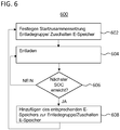
- FIG. 10 is a flowchart illustrating a second discharge mode according to an embodiment.
- the function of the second discharge mode 600 is preferably also implemented in the system controller 140. If the system controller 140 receives a power request to provide electrical power (discharge operation), either the first or second discharge modes may be activated.
- the charge states of energy stores can be adjusted in a targeted manner to form groups of energy stores, which are then, summarized as a first unloading group, suitable for carrying out the first discharge mode, which is described below in the description of FIGS. 7A to 7C is illustrated.
- alternating groups of energy stores are not alternately discharged as in the first discharge mode. Rather, starting from the energy store or the energy storage with the highest state of charge, the or is discharged first or are sequentially, further energy storage in accordance with their charge state or their open circuit voltage "picked up" for unloading, d. H. additionally and not switched on alternately.
- the system controller 140 may be configured to perform the following steps according to the second unloading mode: In turn, the charging states of the energy stores 110 are continuously determined and monitored. In step 702, a start composition of the discharge group for the second discharge mode is established by adding at least one of the plurality of energy stores to the discharge group (second discharge group) depending on the determined charge states of the plurality of energy stores.
- the discharge group may in turn contain the energy store (s) with the highest state of charge.
- the number of energy stores in the second discharge group may also be limited to a maximum number.
- the energy storage of the second discharge group are then closed by closing the corresponding Switched contactors 170 by means of the respective energy storage controllers 130 and thereby discharged 704.
- next or the energy storage device 110 is additionally switched on, or has the highest state of charge of the previously not energized energy storage 110 or have.
- the time of the connection 608 takes place when the charge states of the already connected energy storage 110 have fallen to this state of charge.
- This connection condition is checked in step 606 continuously by determining and monitoring the states of charge. In this way, high balancing currents can be avoided when connecting and charging states of different energy storage can be targeted.
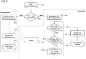
- FIG. 5 shows a flowchart for illustrating a further embodiment.
- the system controller 140 When the system controller 140, for example, receives from the vehicle functional network 150 a signal to start the storage operation (step 502), the system controller 140 checks (step 504) whether a drive or charge operation is pending. In a driving operation 506, the energy storage is discharged.
- the system controller 140 may optionally perform a discharge according to the first discharge mode or the second discharge mode. In FIG. 5 For example, the system control will begin with the first unload mode.
- the system controller 140 determines the energy store (s) with the highest charge state and switches this / these according to the first discharge mode as the first unloading group (step 506).
- the system controller 140 checks whether the current charge states of all energy stores are each less than a predetermined state of charge threshold (x%) (step 508).
- step 516 all remaining, ie not yet switched, energy storage in accordance with their states of charge, such. B. in above Related to FIG. 6 has been described.
- a previously not switched-on energy storage 110 is thus switched on at the time when the charge states of the already connected energy storage reach its charge state level. After all energy stores are switched on, they remain switched on until the drive has finished (518).
- step 508 If the test in step 508 indicates that energy stores 110 exist whose state of charge is greater than a predefined state of charge threshold value (x%), it is checked in step 510 whether the state of charge of the already connected energy stores (ES_on) is lower by a predefined value (y%) of the state of charge has fallen, the energy store (ES_off), which currently has the highest state of charge of the non-energized energy storage.
- a predefined state of charge threshold value x%)
- the driving operation takes place with the aid of the switched-on energy storage of the current discharge group. Only after the highest state of charge of the non-connected energy storage is below the value y%, there is a separation of / the previously connected energy storage (s) and a switch to that / those energy storage, then / currently has the highest state of charge / have.
- the unloading process is then continued with step 508.
- step 504 If the test in step 504 indicates that a charging process of the TES system 100 is pending, charging takes place. Similar to the second discharge mode, the charging operation is performed by successively connecting the energy storage devices, starting with the lowest-state-of-energy storage (s) (step 520). This is followed by a successive connection of further energy stores in step 522 in accordance with their charge states. The remaining energy storage are switched on at the time when the state of charge of the already connected energy storage by charging reaches a level corresponding to the state of charge of the non-connected energy storage. As a result, balancing currents are avoided when connecting as possible. After all the energy stores have been powered on and the TES system 100 is fully charged, charging is terminated (524).
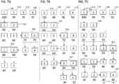
- FIGS. 7A to 7C show a schematic illustration of further embodiments for combining the first discharge mode and the second discharge mode.
- the FIGS. 7A to 7C For better illustration of the discharge principle according to the invention, in turn, by way of example only, show greatly simplified examples with a TES system 100 consisting of only four energy stores 110 ("1" to "4"). The state of charge of each energy store is indicated in each case by the number below the energy store.
- the charging states of the four energy storage devices 110 are distributed as follows:
- the charge state of the energy storage device "1" is 100%, that of the energy storage device “2” 90%, that of the energy storage device “3" 70% and that of the energy storage device "4 "also 70%.
- the number of energy stores for forming a discharge group can be set to a predetermined number N in accordance with the second discharge mode.
- N 2 here.
- the states of charge of the first two energy stores "1" and “2" are first equalized by means of the second discharge mode.
- the energy store "1” is switched on by closing its contactor and discharged to the charge state value of 90%.
- a change takes place into the first discharge mode, in which the two energy stores "1", "2" are assigned and discharged with now the highest state of charge of 90% to the first discharge group 702.
- the two energy stores of the discharge group 702 are discharged to a charge state that lies below the highest charge state by a predefined difference (y%), which the non-connected energy stores "3" and "4" have.
- the difference is set here only as an example to 10%, so that the first two energy storage "1" and “2” are discharged to a state of charge of 60%. Then the two energy storage units “1", “2” are disconnected again by opening the contactors. Instead of the two energy storage "1" and “2” now the energy storage "3" and “4" are defined as a new unloading group 702 and switched on by closing the respective contactors. Subsequently, the two energy storage "3” and "4" are discharged from 70% to 50% state of charge and then separated again by opening the contactors. Instead, in turn, the two energy storage "1” and “2” set as a new discharge group 702, switched on and thus discharged to a state of charge value of 40%.
- FIG. 7B illustrates a further embodiment according to which the charge states of the four energy storage devices 110 are distributed as follows at the beginning of a discharge process: the charge state of the energy storage device "1" is 100%, that of the energy storage device “2" 90%, that of the energy storage device “3" 70% and that of energy storage "4" 50%.
- the states of charge of the first two energy stores "1" and “2" are first equalized by means of the second discharge mode.
- the energy store "1” is switched on by closing its contactor and discharged to the charge state value of 90%.
- a change takes place into the first discharge mode, in which the two energy stores "1", "2" are assigned and discharged with now the highest state of charge of 90% to the first discharge group 702.
- the two energy stores of the discharge group 702 are discharged to a charge state that lies below the highest charge state by a predefined difference (y%), which the non-connected energy stores "3" and "4" have.
- the difference is set here only as an example to 10%, so that the first two energy storage are discharged to a charge state of 60%. Then the two energy storage units "1", “2" are disconnected again by opening the contactors. Instead of the two energy storage "1" and “2” is now the energy storage "3", which then has the highest state of charge of 70%, set as a new discharge group 702 and switched on by closing his contactor. Subsequently, the energy storage "3" is discharged from 70% to 50% state of charge and then disconnected again by opening the contactors. Instead, in turn, the two energy storage "1” and “2” set as new discharge group 702, switched on and discharged to a state of charge value of 40% and then separated again by opening the contactors. Subsequently, those energy stores that now have the highest state of charge, d. H. the energy storage "3" and "4", set as the new discharge group 702, switched on and discharged to a state of charge value of 30%.
- FIG. 7C illustrates another embodiment, according to the beginning of a discharge, the charge states of the four energy storage 110 as in the example of FIG. 7B are distributed.
- the second discharge mode is performed. Accordingly, first the energy storage "1" is switched on with the highest charge state.
- the discharge group 704 consequently consists only of an energy store. After the state of charge of energy storage “1” has fallen to the value of 90% of the (not connected) energy storage with next higher state of charge, this is switched on (energy storage "2").
- Discharge group 704 now consists of two energy stores. After the charging states of the energy storage “1” and “2" have fallen to 70%, which corresponds to the state of charge of the energy storage "3", there is a change to the first discharge mode.
- two of the energy storage are selected with highest charge state as discharge 702, here energy storage "3" and "4", switched on and discharged to a state of charge, which is by the predefined difference (10%) below the highest state of charge of the non-connected energy storage.
Applications Claiming Priority (1)
| Application Number | Priority Date | Filing Date | Title |
|---|---|---|---|
| DE102017123730.5A DE102017123730A1 (de) | 2017-10-12 | 2017-10-12 | Energiespeichersystem mit mehreren parallel verschalteten Energiespeichern und Verfahren zum Betrieb eines Energiespeichersystems |
Publications (3)
| Publication Number | Publication Date |
|---|---|
| EP3470259A2 true EP3470259A2 (fr) | 2019-04-17 |
| EP3470259A3 EP3470259A3 (fr) | 2019-05-15 |
| EP3470259B1 EP3470259B1 (fr) | 2022-07-27 |
Family
ID=63592569
Family Applications (1)
| Application Number | Title | Priority Date | Filing Date |
|---|---|---|---|
| EP18194459.6A Active EP3470259B1 (fr) | 2017-10-12 | 2018-09-14 | Système d'accumulateurs d'énergie doté d'une pluralité d'accumulateurs d'énergie couplés en parallèle et procédé de fonctionnement d'un système d'accumulateurs d'énergie |
Country Status (2)
| Country | Link |
|---|---|
| EP (1) | EP3470259B1 (fr) |
| DE (1) | DE102017123730A1 (fr) |
Cited By (1)
| Publication number | Priority date | Publication date | Assignee | Title |
|---|---|---|---|---|
| CN114274841A (zh) * | 2021-08-09 | 2022-04-05 | 中车资阳机车有限公司 | 一种多支路动力电池系统并联直挂控制方法 |
Family Cites Families (6)
| Publication number | Priority date | Publication date | Assignee | Title |
|---|---|---|---|---|
| JP5618359B2 (ja) * | 2010-08-02 | 2014-11-05 | Necエナジーデバイス株式会社 | 二次電池パック接続制御方法、および、蓄電システム |
| DE102010035073A1 (de) * | 2010-08-21 | 2014-06-18 | Jens Goldenstein | Energie-Management-System |
| US9166419B2 (en) * | 2011-10-31 | 2015-10-20 | Robert Bosch Gmbh | Intelligent charging and discharging system for parallel configuration of series cells with semiconductor switching |
| DE102014216876A1 (de) * | 2014-08-25 | 2016-02-25 | Robert Bosch Gmbh | Verfahren und Vorrichtung zum Steuern eines Ladevorgangs einer Mehrzahl von elektrochemischen Energiespeichereinrichtungen sowie Verfahren und Vorrichtung zum Durchführen eines Ladevorgangs einer Mehrzahl von elektrochemischen Energiespeichereinrichtungen |
| CN104377758A (zh) * | 2014-10-24 | 2015-02-25 | 北京凌云智能科技有限公司 | 一种电池切换方法、电池管理系统及电源装置 |
| WO2016074216A1 (fr) * | 2014-11-14 | 2016-05-19 | Robert Bosch Gmbh | Système de stockage d'énergie à base de blocs-batterie |
-
2017
- 2017-10-12 DE DE102017123730.5A patent/DE102017123730A1/de active Pending
-
2018
- 2018-09-14 EP EP18194459.6A patent/EP3470259B1/fr active Active
Cited By (2)
| Publication number | Priority date | Publication date | Assignee | Title |
|---|---|---|---|---|
| CN114274841A (zh) * | 2021-08-09 | 2022-04-05 | 中车资阳机车有限公司 | 一种多支路动力电池系统并联直挂控制方法 |
| CN114274841B (zh) * | 2021-08-09 | 2023-05-23 | 中车资阳机车有限公司 | 一种多支路动力电池系统并联直挂控制方法 |
Also Published As
| Publication number | Publication date |
|---|---|
| DE102017123730A1 (de) | 2019-04-18 |
| EP3470259B1 (fr) | 2022-07-27 |
| EP3470259A3 (fr) | 2019-05-15 |
Similar Documents
| Publication | Publication Date | Title |
|---|---|---|
| DE102019114701A1 (de) | Selbstausgleichende Schaltsteuerung eines wiederaufladbaren Doppelpack-Energiespeichersystems mit Reihen- und Parallelmodi | |
| DE3936638C1 (en) | Ensuring electrical power supply in motor vehicle - grouping electrical appliances according to their importance for safety of vehicle | |
| WO2017102414A1 (fr) | Circuit de charge et procédé de charge pour un système électrique d'accumulation d'énergie | |
| EP3323667B1 (fr) | Système de stockage d'énergie de traction à limitation de fonctionnement | |
| DE102012222102A1 (de) | Aktives steuersystem für einen niederspannungs- gleichspannungswandler in einem elektrofahrzeug | |
| WO2012095207A1 (fr) | Procédé pour commander une batterie et batterie pour réaliser le procédé | |
| EP3342629B1 (fr) | Technique de connexion variable d'un système d'accumulation d'énergie de traction | |
| WO2014086651A2 (fr) | Procédé pour une liaison commandée de plusieurs branches d'un réseau de bord d'un véhicule, unité de commande pour exécuter le procédé ainsi que réseau de bord | |
| DE102013200763A1 (de) | System und verfahren für das fahrzeugenergiemanagement | |
| DE102010009260A1 (de) | Einrichtung zur Versorgung eines Bordnetzes | |
| DE102020118904A1 (de) | Bordseitiger wechselstromgenerator für power-to-the-box in fahrzeugen mit einer brennkraftmaschine | |
| EP3720733B1 (fr) | Procédé de commande d'une installation électrique d'un véhicule à moteur à entraînement électrique, dotée de plusieurs batteries et installation électrique d'un véhicule à entraînement électrique | |
| DE102020123570A1 (de) | Steuerung eines gemischten batteriepacks | |
| DE102019120882A1 (de) | System und verfahren zum auswählen von wandlern, um nichtnullstrom in verteiltem wandlersystem durchzuführen | |
| EP3067240B1 (fr) | Procede d'alimentation en tension d'un reseau de bord d'un vehicule automobile | |
| DE102018108041B4 (de) | Verfahren zum Aufschalten mehrerer, parallel verschalteter Batterieblöcke | |
| DE102015204300B3 (de) | Verfahren zum Laden einer mehrteiligen elektrochemischen Energiespeichereinrichtung, Energiespeichersystem und Kraftfahrzeug mit Energiespeichersystem | |
| EP3273507B1 (fr) | Système accumulateur d'énergie de traction pour véhicule | |
| WO2021089281A1 (fr) | Système de stockage à plusieurs tensions pour un véhicule au moins partiellement électrique | |
| EP3470259B1 (fr) | Système d'accumulateurs d'énergie doté d'une pluralité d'accumulateurs d'énergie couplés en parallèle et procédé de fonctionnement d'un système d'accumulateurs d'énergie | |
| EP3309003B1 (fr) | Système accumulateur d'énergie de traction pour véhicule | |
| DE102020130682A1 (de) | Ausgleichen von zellen einer traktionsbatterie unter verwendung einer statistischen analyse | |
| DE102011077701A1 (de) | Fahrzeug-Batterie mit mehreren Spannungslagen und Verfahren zum Betrieb einer Fahrzeug-Batterie mit mehreren Spannungslagen | |
| DE102020206520A1 (de) | Verfahren zum Betreiben eines Batteriesystems | |
| WO2019007879A1 (fr) | Appareil de commande principale pour un système de batterie |
Legal Events
| Date | Code | Title | Description |
|---|---|---|---|
| PUAI | Public reference made under article 153(3) epc to a published international application that has entered the european phase |
Free format text: ORIGINAL CODE: 0009012 |
|
| STAA | Information on the status of an ep patent application or granted ep patent |
Free format text: STATUS: THE APPLICATION HAS BEEN PUBLISHED |
|
| REG | Reference to a national code |
Ref country code: DE Ref legal event code: R079 Ref document number: 502018010228 Country of ref document: DE Free format text: PREVIOUS MAIN CLASS: B60L0058210000 Ipc: B60L0058180000 |
|
| PUAL | Search report despatched |
Free format text: ORIGINAL CODE: 0009013 |
|
| AK | Designated contracting states |
Kind code of ref document: A2 Designated state(s): AL AT BE BG CH CY CZ DE DK EE ES FI FR GB GR HR HU IE IS IT LI LT LU LV MC MK MT NL NO PL PT RO RS SE SI SK SM TR |
|
| AX | Request for extension of the european patent |
Extension state: BA ME |
|
| AK | Designated contracting states |
Kind code of ref document: A3 Designated state(s): AL AT BE BG CH CY CZ DE DK EE ES FI FR GB GR HR HU IE IS IT LI LT LU LV MC MK MT NL NO PL PT RO RS SE SI SK SM TR |
|
| AX | Request for extension of the european patent |
Extension state: BA ME |
|
| RIC1 | Information provided on ipc code assigned before grant |
Ipc: B60L 58/18 20190101AFI20190409BHEP Ipc: H02J 7/00 20060101ALI20190409BHEP Ipc: B60L 58/21 20190101ALI20190409BHEP |
|
| RAP1 | Party data changed (applicant data changed or rights of an application transferred) |
Owner name: MAN TRUCK & BUS SE |
|
| STAA | Information on the status of an ep patent application or granted ep patent |
Free format text: STATUS: REQUEST FOR EXAMINATION WAS MADE |
|
| 17P | Request for examination filed |
Effective date: 20191112 |
|
| RBV | Designated contracting states (corrected) |
Designated state(s): AL AT BE BG CH CY CZ DE DK EE ES FI FR GB GR HR HU IE IS IT LI LT LU LV MC MK MT NL NO PL PT RO RS SE SI SK SM TR |
|
| STAA | Information on the status of an ep patent application or granted ep patent |
Free format text: STATUS: EXAMINATION IS IN PROGRESS |
|
| 17Q | First examination report despatched |
Effective date: 20200814 |
|
| STAA | Information on the status of an ep patent application or granted ep patent |
Free format text: STATUS: EXAMINATION IS IN PROGRESS |
|
| GRAP | Despatch of communication of intention to grant a patent |
Free format text: ORIGINAL CODE: EPIDOSNIGR1 |
|
| STAA | Information on the status of an ep patent application or granted ep patent |
Free format text: STATUS: GRANT OF PATENT IS INTENDED |
|
| INTG | Intention to grant announced |
Effective date: 20211027 |
|
| RIN1 | Information on inventor provided before grant (corrected) |
Inventor name: KRATZER, SEBASTIAN Inventor name: WEBER, BENJAMIN |
|
| GRAJ | Information related to disapproval of communication of intention to grant by the applicant or resumption of examination proceedings by the epo deleted |
Free format text: ORIGINAL CODE: EPIDOSDIGR1 |
|
| STAA | Information on the status of an ep patent application or granted ep patent |
Free format text: STATUS: EXAMINATION IS IN PROGRESS |
|
| INTC | Intention to grant announced (deleted) | ||
| GRAP | Despatch of communication of intention to grant a patent |
Free format text: ORIGINAL CODE: EPIDOSNIGR1 |
|
| STAA | Information on the status of an ep patent application or granted ep patent |
Free format text: STATUS: GRANT OF PATENT IS INTENDED |
|
| INTG | Intention to grant announced |
Effective date: 20220309 |
|
| GRAS | Grant fee paid |
Free format text: ORIGINAL CODE: EPIDOSNIGR3 |
|
| GRAA | (expected) grant |
Free format text: ORIGINAL CODE: 0009210 |
|
| STAA | Information on the status of an ep patent application or granted ep patent |
Free format text: STATUS: THE PATENT HAS BEEN GRANTED |
|
| AK | Designated contracting states |
Kind code of ref document: B1 Designated state(s): AL AT BE BG CH CY CZ DE DK EE ES FI FR GB GR HR HU IE IS IT LI LT LU LV MC MK MT NL NO PL PT RO RS SE SI SK SM TR |
|
| REG | Reference to a national code |
Ref country code: CH Ref legal event code: EP |
|
| REG | Reference to a national code |
Ref country code: AT Ref legal event code: REF Ref document number: 1506856 Country of ref document: AT Kind code of ref document: T Effective date: 20220815 |
|
| REG | Reference to a national code |
Ref country code: DE Ref legal event code: R096 Ref document number: 502018010228 Country of ref document: DE |
|
| REG | Reference to a national code |
Ref country code: NL Ref legal event code: FP |
|
| REG | Reference to a national code |
Ref country code: IE Ref legal event code: FG4D Free format text: LANGUAGE OF EP DOCUMENT: GERMAN |
|
| REG | Reference to a national code |
Ref country code: SE Ref legal event code: TRGR |
|
| REG | Reference to a national code |
Ref country code: LT Ref legal event code: MG9D |
|
| PG25 | Lapsed in a contracting state [announced via postgrant information from national office to epo] |
Ref country code: RS Free format text: LAPSE BECAUSE OF FAILURE TO SUBMIT A TRANSLATION OF THE DESCRIPTION OR TO PAY THE FEE WITHIN THE PRESCRIBED TIME-LIMIT Effective date: 20220727 Ref country code: PT Free format text: LAPSE BECAUSE OF FAILURE TO SUBMIT A TRANSLATION OF THE DESCRIPTION OR TO PAY THE FEE WITHIN THE PRESCRIBED TIME-LIMIT Effective date: 20221128 Ref country code: NO Free format text: LAPSE BECAUSE OF FAILURE TO SUBMIT A TRANSLATION OF THE DESCRIPTION OR TO PAY THE FEE WITHIN THE PRESCRIBED TIME-LIMIT Effective date: 20221027 Ref country code: LV Free format text: LAPSE BECAUSE OF FAILURE TO SUBMIT A TRANSLATION OF THE DESCRIPTION OR TO PAY THE FEE WITHIN THE PRESCRIBED TIME-LIMIT Effective date: 20220727 Ref country code: LT Free format text: LAPSE BECAUSE OF FAILURE TO SUBMIT A TRANSLATION OF THE DESCRIPTION OR TO PAY THE FEE WITHIN THE PRESCRIBED TIME-LIMIT Effective date: 20220727 Ref country code: FI Free format text: LAPSE BECAUSE OF FAILURE TO SUBMIT A TRANSLATION OF THE DESCRIPTION OR TO PAY THE FEE WITHIN THE PRESCRIBED TIME-LIMIT Effective date: 20220727 Ref country code: ES Free format text: LAPSE BECAUSE OF FAILURE TO SUBMIT A TRANSLATION OF THE DESCRIPTION OR TO PAY THE FEE WITHIN THE PRESCRIBED TIME-LIMIT Effective date: 20220727 |
|
| PG25 | Lapsed in a contracting state [announced via postgrant information from national office to epo] |
Ref country code: PL Free format text: LAPSE BECAUSE OF FAILURE TO SUBMIT A TRANSLATION OF THE DESCRIPTION OR TO PAY THE FEE WITHIN THE PRESCRIBED TIME-LIMIT Effective date: 20220727 Ref country code: IS Free format text: LAPSE BECAUSE OF FAILURE TO SUBMIT A TRANSLATION OF THE DESCRIPTION OR TO PAY THE FEE WITHIN THE PRESCRIBED TIME-LIMIT Effective date: 20221127 Ref country code: HR Free format text: LAPSE BECAUSE OF FAILURE TO SUBMIT A TRANSLATION OF THE DESCRIPTION OR TO PAY THE FEE WITHIN THE PRESCRIBED TIME-LIMIT Effective date: 20220727 Ref country code: GR Free format text: LAPSE BECAUSE OF FAILURE TO SUBMIT A TRANSLATION OF THE DESCRIPTION OR TO PAY THE FEE WITHIN THE PRESCRIBED TIME-LIMIT Effective date: 20221028 |
|
| PG25 | Lapsed in a contracting state [announced via postgrant information from national office to epo] |
Ref country code: SM Free format text: LAPSE BECAUSE OF FAILURE TO SUBMIT A TRANSLATION OF THE DESCRIPTION OR TO PAY THE FEE WITHIN THE PRESCRIBED TIME-LIMIT Effective date: 20220727 Ref country code: RO Free format text: LAPSE BECAUSE OF FAILURE TO SUBMIT A TRANSLATION OF THE DESCRIPTION OR TO PAY THE FEE WITHIN THE PRESCRIBED TIME-LIMIT Effective date: 20220727 Ref country code: MC Free format text: LAPSE BECAUSE OF FAILURE TO SUBMIT A TRANSLATION OF THE DESCRIPTION OR TO PAY THE FEE WITHIN THE PRESCRIBED TIME-LIMIT Effective date: 20220727 Ref country code: DK Free format text: LAPSE BECAUSE OF FAILURE TO SUBMIT A TRANSLATION OF THE DESCRIPTION OR TO PAY THE FEE WITHIN THE PRESCRIBED TIME-LIMIT Effective date: 20220727 Ref country code: CZ Free format text: LAPSE BECAUSE OF FAILURE TO SUBMIT A TRANSLATION OF THE DESCRIPTION OR TO PAY THE FEE WITHIN THE PRESCRIBED TIME-LIMIT Effective date: 20220727 |
|
| REG | Reference to a national code |
Ref country code: CH Ref legal event code: PL |
|
| REG | Reference to a national code |
Ref country code: DE Ref legal event code: R097 Ref document number: 502018010228 Country of ref document: DE |
|
| REG | Reference to a national code |
Ref country code: BE Ref legal event code: MM Effective date: 20220930 |
|
| PG25 | Lapsed in a contracting state [announced via postgrant information from national office to epo] |
Ref country code: SK Free format text: LAPSE BECAUSE OF FAILURE TO SUBMIT A TRANSLATION OF THE DESCRIPTION OR TO PAY THE FEE WITHIN THE PRESCRIBED TIME-LIMIT Effective date: 20220727 Ref country code: EE Free format text: LAPSE BECAUSE OF FAILURE TO SUBMIT A TRANSLATION OF THE DESCRIPTION OR TO PAY THE FEE WITHIN THE PRESCRIBED TIME-LIMIT Effective date: 20220727 |
|
| PLBE | No opposition filed within time limit |
Free format text: ORIGINAL CODE: 0009261 |
|
| STAA | Information on the status of an ep patent application or granted ep patent |
Free format text: STATUS: NO OPPOSITION FILED WITHIN TIME LIMIT |
|
| GBPC | Gb: european patent ceased through non-payment of renewal fee |
Effective date: 20221027 |
|
| PG25 | Lapsed in a contracting state [announced via postgrant information from national office to epo] |
Ref country code: AL Free format text: LAPSE BECAUSE OF FAILURE TO SUBMIT A TRANSLATION OF THE DESCRIPTION OR TO PAY THE FEE WITHIN THE PRESCRIBED TIME-LIMIT Effective date: 20220727 Ref country code: LU Free format text: LAPSE BECAUSE OF NON-PAYMENT OF DUE FEES Effective date: 20220914 |
|
| 26N | No opposition filed |
Effective date: 20230502 |
|
| PG25 | Lapsed in a contracting state [announced via postgrant information from national office to epo] |
Ref country code: LI Free format text: LAPSE BECAUSE OF NON-PAYMENT OF DUE FEES Effective date: 20220930 Ref country code: IE Free format text: LAPSE BECAUSE OF NON-PAYMENT OF DUE FEES Effective date: 20220914 Ref country code: CH Free format text: LAPSE BECAUSE OF NON-PAYMENT OF DUE FEES Effective date: 20220930 |
|
| PG25 | Lapsed in a contracting state [announced via postgrant information from national office to epo] |
Ref country code: SI Free format text: LAPSE BECAUSE OF FAILURE TO SUBMIT A TRANSLATION OF THE DESCRIPTION OR TO PAY THE FEE WITHIN THE PRESCRIBED TIME-LIMIT Effective date: 20220727 |
|
| PG25 | Lapsed in a contracting state [announced via postgrant information from national office to epo] |
Ref country code: BE Free format text: LAPSE BECAUSE OF NON-PAYMENT OF DUE FEES Effective date: 20220930 |
|
| PG25 | Lapsed in a contracting state [announced via postgrant information from national office to epo] |
Ref country code: GB Free format text: LAPSE BECAUSE OF NON-PAYMENT OF DUE FEES Effective date: 20221027 |
|
| PGFP | Annual fee paid to national office [announced via postgrant information from national office to epo] |
Ref country code: NL Payment date: 20230926 Year of fee payment: 6 Ref country code: IT Payment date: 20230920 Year of fee payment: 6 |
|
| PGFP | Annual fee paid to national office [announced via postgrant information from national office to epo] |
Ref country code: SE Payment date: 20230926 Year of fee payment: 6 Ref country code: FR Payment date: 20230926 Year of fee payment: 6 Ref country code: DE Payment date: 20230928 Year of fee payment: 6 |
|
| PG25 | Lapsed in a contracting state [announced via postgrant information from national office to epo] |
Ref country code: HU Free format text: LAPSE BECAUSE OF FAILURE TO SUBMIT A TRANSLATION OF THE DESCRIPTION OR TO PAY THE FEE WITHIN THE PRESCRIBED TIME-LIMIT; INVALID AB INITIO Effective date: 20180914 |
|
| PG25 | Lapsed in a contracting state [announced via postgrant information from national office to epo] |
Ref country code: CY Free format text: LAPSE BECAUSE OF FAILURE TO SUBMIT A TRANSLATION OF THE DESCRIPTION OR TO PAY THE FEE WITHIN THE PRESCRIBED TIME-LIMIT Effective date: 20220727 |