EP3470128A1 - Server dust collector - Google Patents
Server dust collector Download PDFInfo
- Publication number
- EP3470128A1 EP3470128A1 EP18153464.5A EP18153464A EP3470128A1 EP 3470128 A1 EP3470128 A1 EP 3470128A1 EP 18153464 A EP18153464 A EP 18153464A EP 3470128 A1 EP3470128 A1 EP 3470128A1
- Authority
- EP
- European Patent Office
- Prior art keywords
- filter
- coolant gas
- centrifugal force
- filter unit
- server
- Prior art date
- Legal status (The legal status is an assumption and is not a legal conclusion. Google has not performed a legal analysis and makes no representation as to the accuracy of the status listed.)
- Granted
Links
Images



Classifications
-
- B—PERFORMING OPERATIONS; TRANSPORTING
- B01—PHYSICAL OR CHEMICAL PROCESSES OR APPARATUS IN GENERAL
- B01D—SEPARATION
- B01D50/00—Combinations of methods or devices for separating particles from gases or vapours
- B01D50/20—Combinations of devices covered by groups B01D45/00 and B01D46/00
-
- B—PERFORMING OPERATIONS; TRANSPORTING
- B01—PHYSICAL OR CHEMICAL PROCESSES OR APPARATUS IN GENERAL
- B01D—SEPARATION
- B01D45/00—Separating dispersed particles from gases or vapours by gravity, inertia, or centrifugal forces
- B01D45/12—Separating dispersed particles from gases or vapours by gravity, inertia, or centrifugal forces by centrifugal forces
- B01D45/16—Separating dispersed particles from gases or vapours by gravity, inertia, or centrifugal forces by centrifugal forces generated by the winding course of the gas stream, the centrifugal forces being generated solely or partly by mechanical means, e.g. fixed swirl vanes
-
- B—PERFORMING OPERATIONS; TRANSPORTING
- B01—PHYSICAL OR CHEMICAL PROCESSES OR APPARATUS IN GENERAL
- B01D—SEPARATION
- B01D46/00—Filters or filtering processes specially modified for separating dispersed particles from gases or vapours
- B01D46/0039—Filters or filtering processes specially modified for separating dispersed particles from gases or vapours with flow guiding by feed or discharge devices
- B01D46/0041—Filters or filtering processes specially modified for separating dispersed particles from gases or vapours with flow guiding by feed or discharge devices for feeding
- B01D46/0045—Filters or filtering processes specially modified for separating dispersed particles from gases or vapours with flow guiding by feed or discharge devices for feeding by using vanes
-
- B—PERFORMING OPERATIONS; TRANSPORTING
- B01—PHYSICAL OR CHEMICAL PROCESSES OR APPARATUS IN GENERAL
- B01D—SEPARATION
- B01D46/00—Filters or filtering processes specially modified for separating dispersed particles from gases or vapours
- B01D46/10—Particle separators, e.g. dust precipitators, using filter plates, sheets or pads having plane surfaces
-
- B—PERFORMING OPERATIONS; TRANSPORTING
- B01—PHYSICAL OR CHEMICAL PROCESSES OR APPARATUS IN GENERAL
- B01D—SEPARATION
- B01D46/00—Filters or filtering processes specially modified for separating dispersed particles from gases or vapours
- B01D46/30—Particle separators, e.g. dust precipitators, using loose filtering material
-
- B—PERFORMING OPERATIONS; TRANSPORTING
- B01—PHYSICAL OR CHEMICAL PROCESSES OR APPARATUS IN GENERAL
- B01D—SEPARATION
- B01D53/00—Separation of gases or vapours; Recovering vapours of volatile solvents from gases; Chemical or biological purification of waste gases, e.g. engine exhaust gases, smoke, fumes, flue gases, aerosols
- B01D53/02—Separation of gases or vapours; Recovering vapours of volatile solvents from gases; Chemical or biological purification of waste gases, e.g. engine exhaust gases, smoke, fumes, flue gases, aerosols by adsorption, e.g. preparative gas chromatography
- B01D53/04—Separation of gases or vapours; Recovering vapours of volatile solvents from gases; Chemical or biological purification of waste gases, e.g. engine exhaust gases, smoke, fumes, flue gases, aerosols by adsorption, e.g. preparative gas chromatography with stationary adsorbents
- B01D53/0407—Constructional details of adsorbing systems
-
- B—PERFORMING OPERATIONS; TRANSPORTING
- B03—SEPARATION OF SOLID MATERIALS USING LIQUIDS OR USING PNEUMATIC TABLES OR JIGS; MAGNETIC OR ELECTROSTATIC SEPARATION OF SOLID MATERIALS FROM SOLID MATERIALS OR FLUIDS; SEPARATION BY HIGH-VOLTAGE ELECTRIC FIELDS
- B03C—MAGNETIC OR ELECTROSTATIC SEPARATION OF SOLID MATERIALS FROM SOLID MATERIALS OR FLUIDS; SEPARATION BY HIGH-VOLTAGE ELECTRIC FIELDS
- B03C3/00—Separating dispersed particles from gases or vapour, e.g. air, by electrostatic effect
- B03C3/017—Combinations of electrostatic separation with other processes, not otherwise provided for
-
- B—PERFORMING OPERATIONS; TRANSPORTING
- B04—CENTRIFUGAL APPARATUS OR MACHINES FOR CARRYING-OUT PHYSICAL OR CHEMICAL PROCESSES
- B04C—APPARATUS USING FREE VORTEX FLOW, e.g. CYCLONES
- B04C9/00—Combinations with other devices, e.g. fans, expansion chambers, diffusors, water locks
-
- H—ELECTRICITY
- H05—ELECTRIC TECHNIQUES NOT OTHERWISE PROVIDED FOR
- H05K—PRINTED CIRCUITS; CASINGS OR CONSTRUCTIONAL DETAILS OF ELECTRIC APPARATUS; MANUFACTURE OF ASSEMBLAGES OF ELECTRICAL COMPONENTS
- H05K7/00—Constructional details common to different types of electric apparatus
- H05K7/20—Modifications to facilitate cooling, ventilating, or heating
- H05K7/20009—Modifications to facilitate cooling, ventilating, or heating using a gaseous coolant in electronic enclosures
- H05K7/20136—Forced ventilation, e.g. by fans
- H05K7/20181—Filters; Louvers
-
- H—ELECTRICITY
- H05—ELECTRIC TECHNIQUES NOT OTHERWISE PROVIDED FOR
- H05K—PRINTED CIRCUITS; CASINGS OR CONSTRUCTIONAL DETAILS OF ELECTRIC APPARATUS; MANUFACTURE OF ASSEMBLAGES OF ELECTRICAL COMPONENTS
- H05K7/00—Constructional details common to different types of electric apparatus
- H05K7/20—Modifications to facilitate cooling, ventilating, or heating
- H05K7/20709—Modifications to facilitate cooling, ventilating, or heating for server racks or cabinets; for data centers, e.g. 19-inch computer racks
- H05K7/20718—Forced ventilation of a gaseous coolant
- H05K7/20727—Forced ventilation of a gaseous coolant within server blades for removing heat from heat source
-
- H—ELECTRICITY
- H05—ELECTRIC TECHNIQUES NOT OTHERWISE PROVIDED FOR
- H05K—PRINTED CIRCUITS; CASINGS OR CONSTRUCTIONAL DETAILS OF ELECTRIC APPARATUS; MANUFACTURE OF ASSEMBLAGES OF ELECTRICAL COMPONENTS
- H05K7/00—Constructional details common to different types of electric apparatus
- H05K7/20—Modifications to facilitate cooling, ventilating, or heating
- H05K7/20709—Modifications to facilitate cooling, ventilating, or heating for server racks or cabinets; for data centers, e.g. 19-inch computer racks
- H05K7/20718—Forced ventilation of a gaseous coolant
- H05K7/20736—Forced ventilation of a gaseous coolant within cabinets for removing heat from server blades
-
- B—PERFORMING OPERATIONS; TRANSPORTING
- B01—PHYSICAL OR CHEMICAL PROCESSES OR APPARATUS IN GENERAL
- B01D—SEPARATION
- B01D2253/00—Adsorbents used in seperation treatment of gases and vapours
- B01D2253/10—Inorganic adsorbents
- B01D2253/102—Carbon
-
- B—PERFORMING OPERATIONS; TRANSPORTING
- B01—PHYSICAL OR CHEMICAL PROCESSES OR APPARATUS IN GENERAL
- B01D—SEPARATION
- B01D2257/00—Components to be removed
- B01D2257/70—Organic compounds not provided for in groups B01D2257/00 - B01D2257/602
- B01D2257/708—Volatile organic compounds V.O.C.'s
-
- B—PERFORMING OPERATIONS; TRANSPORTING
- B01—PHYSICAL OR CHEMICAL PROCESSES OR APPARATUS IN GENERAL
- B01D—SEPARATION
- B01D2279/00—Filters adapted for separating dispersed particles from gases or vapours specially modified for specific uses
- B01D2279/45—Filters adapted for separating dispersed particles from gases or vapours specially modified for specific uses for electronic devices, e.g. computers, hard-discs, mobile phones
-
- B—PERFORMING OPERATIONS; TRANSPORTING
- B01—PHYSICAL OR CHEMICAL PROCESSES OR APPARATUS IN GENERAL
- B01D—SEPARATION
- B01D46/00—Filters or filtering processes specially modified for separating dispersed particles from gases or vapours
- B01D46/0002—Casings; Housings; Frame constructions
-
- B—PERFORMING OPERATIONS; TRANSPORTING
- B01—PHYSICAL OR CHEMICAL PROCESSES OR APPARATUS IN GENERAL
- B01D—SEPARATION
- B01D46/00—Filters or filtering processes specially modified for separating dispersed particles from gases or vapours
- B01D46/0002—Casings; Housings; Frame constructions
- B01D46/0004—Details of removable closures, lids, caps or filter heads
-
- B—PERFORMING OPERATIONS; TRANSPORTING
- B01—PHYSICAL OR CHEMICAL PROCESSES OR APPARATUS IN GENERAL
- B01D—SEPARATION
- B01D46/00—Filters or filtering processes specially modified for separating dispersed particles from gases or vapours
- B01D46/0002—Casings; Housings; Frame constructions
- B01D46/0005—Mounting of filtering elements within casings, housings or frames
-
- B—PERFORMING OPERATIONS; TRANSPORTING
- B01—PHYSICAL OR CHEMICAL PROCESSES OR APPARATUS IN GENERAL
- B01D—SEPARATION
- B01D46/00—Filters or filtering processes specially modified for separating dispersed particles from gases or vapours
- B01D46/0002—Casings; Housings; Frame constructions
- B01D46/0005—Mounting of filtering elements within casings, housings or frames
- B01D46/0008—Two or more filter elements not fluidly connected positioned in the same housing
-
- B—PERFORMING OPERATIONS; TRANSPORTING
- B04—CENTRIFUGAL APPARATUS OR MACHINES FOR CARRYING-OUT PHYSICAL OR CHEMICAL PROCESSES
- B04C—APPARATUS USING FREE VORTEX FLOW, e.g. CYCLONES
- B04C9/00—Combinations with other devices, e.g. fans, expansion chambers, diffusors, water locks
- B04C2009/002—Combinations with other devices, e.g. fans, expansion chambers, diffusors, water locks with external filters
Definitions
- the present disclosure is directed to protective devices for servers and other electrical equipment that utilize air as a coolant. More particularly, the disclosure provides an apparatus for use in reducing dust, pollen, and other particulate matter buildup in and onto servers and other electrical devices.
- Servers are known to accumulate a particulate buildup, both by drawing in ambient fluid, such as air, into the server; as well as from static electrical forces which act as an attractant to accumulate particulates from the air present in the environment surrounding the server.
- ambient fluid such as air
- the prior art has attempted to reduce the particulates in the environment surrounding the server through conditioning the immediate environment by placing the servers in a "clean room".
- the particulates which cause buildup on known servers include many forms of "dust”, which can include viruses, bacteria, smoke, and allergens.
- allergens are pollen or spores from plant life, hair or dead skin cells from animal life, and other inorganic matter in the form of finely entrained particulates including nano-particles that exist in Brownian movement in isolated air pockets, carried in moving air streams, or are adsorbed onto solid surfaces.
- "Clean rooms” are expensive to create and maintain in a sterile condition that is free of particulates because of the need for human personnel to enter and exit these rooms to access, maintain, repair, and attend to the servers contained therein.
- server usage has become so predominant in many businesses, many of these businesses, particularly small businesses, cannot afford the cost of creating and maintaining clean rooms to house their servers.
- a first embodiment provides for an apparatus in combination with a server, either as an original equipment manufacture (“OEM”) or as a retrofit unit that can be mounted onto a server.
- a server will have at least one orifice inlet (although there are typically many) into which ambient air will be drawn into the housing of the server, under the influence of a fan, so as to act as a coolant to reduce the temperature of the server by removing heat therefrom by means of convection.
- the retrofit apparatus will include a lattice support or framework which can be fastened to the housing of the server over the inlet orifice(s) and the use of at least one elastic strip to fill-in any gap between the retrofit apparatus and the server.
- the support will include at least one aperture into which a replaceable surface filter is inserted and positioned for effectively covering the inlet orifice(s) in the housing of the server.
- the replaceable surface filter is able to mechanically retain particulates flowing therethrough, and can optionally retain particulates therein by electrostatic forces as well.
- This filter can also be a High Efficiency Particulate Accumulator ("HEPA") filter.
- HEPA High Efficiency Particulate Accumulator
- the HEPA filter can capture many bacteria, viruses, allergens (such as pollens, spores, smoke, etc.), and other relatively small organisms or particles, including nano-particles, that can be found in ambient air.
- VOC volatile organic compounds
- This third filter can be combined as a separate layer on the replaceable surface filter or, in some instances, can be a separate, stand-alone filter, placed downstream of the replaceable surface filter.
- This third filter may be a charcoal filter.
- the lattice support or framework can also house a number of centrifugal fiber filter units (positioned upstream of the surface filter) which centrifugal filter units utilize centrifugal force to impel entrained particulates through individual fiber filter units associated with each centrifugal force unit.
- the fiber filter units fed by the centrifugal force, effectively reduce the particulate content of the ambient air such that the flow through centrifugal fiber filter units to assure that the replaceable surface filter will not be prematurely filled with particulate matter -- thereby extending the service life of the replaceable surface filter.
- the centrifugal force in each of the centrifugal force filter units is created by a static device channeling the intake flow of fluid from a relatively larger inlet opening and discharging the fluid through a relatively smaller outlet opening.
- the centrifugal force will, by reason of a pressure drop created by the physical shape and dimensions of the static centrifugal device, deliver entrained particulates into a filter unit immediately downstream of the outlet of the centrifugal device where the particulates will be captured.
- Such downstream filter unit may take the form of a filter tank which is filled with a plurality of fibers.
- the filter tank may house other types of filtering media, such as woven or non-woven fabrics, batts, tapes, blankets, and similar filtering media.
- the outlet of the centrifugal device, downstream of the filter unit preferably takes the shape of a plurality of orifices in the back wall of the filter tank. The exiting air, at least partially cleaned of particulates, will then be directed towards the replaceable surface filter.
- the elastic strips can be utilized to permit access to the housing of the server for example, to permit cable outlet from the server to peripheral equipment.
- FIG. 1 Shown at 10 in FIG. 1 is the combination of a server 12 and its attached filter assembly 14.
- FIG. 2 shows an exploded view of the filter assembly 14 of FIG. 1 .
- Server 12 can be a rack server configured to be received in a slot of a rack (not shown).
- the various embodiments are not limited in this regard. Rather the filter assembly 14 can be used with other types of computing devices.
- a server 12 is exemplary of the type of electronic component to which the filter assembly 14 may be employed in combination, it is to be understood that other electronic components, other than a server, may be used in combination with filter assembly 14. Such other electronic components could include storage, switch and similar electrical systems.
- Filter assembly 14 comprises a replaceable surface filter 15 according to a first embodiment.
- Server 12 (the internal components thereof not being illustrated) comprises a housing 13 upon which filter assembly 14 is mounted.
- a pair of elastic strips 16, 17 are positioned between the filter assembly 14 and the server 12 to permit access to input/output electrical sockets (not shown) in the server 12.
- only one elastic strip could be used, provided that it can extend down (or up) both side surfaces occupied by elastic strips 16 and 17.
- the elastic strips are provided to permit cable(s) to pass from the server 12 to peripheral equipment (not shown) or electrical connections (including internet access) associated with server 12. Thus, cables (not shown) could be connected to the server and exit beneath the elastic strips 16, 17.
- the cables can be bundled by a feed-through device, an inner rubber component of the feed-through device will force the air-gap within the cables be minimized or eliminated, thereby minimizing/eliminating any air gap created by the cables passing through/beneath the elastic strips 16, 17.
- FIG. 2 is an exploded view of the filter assembly 14 of FIG. 1 .
- Filter assembly 14 comprises a lattice support or framework 18.
- the lattice support or framework 18 can be formed of metal, plastic, or a composite of metal and plastic.
- plastic any of the moldable polymers, copolymers, terpolymers, or blends of polyethylene, polypropylene, polystyrene, polyvinylchloride, polyacrylates, epoxies and rubbery polymers, and acrylonitiles, could be employed to form lattice support or framework 18.
- the polyacrylates include ethyl methacrylate and methyl methacrylate, among others.
- the acrylonitriles include terpolymers such as acrylonitrile butadiene styrene ("ABS").
- ABS acrylonitrile butadiene styrene
- these plastics are reinforced with fillers including carbon black, and preferably including fibers, particularly carbon or graphite fibers, to prevent the build-up of a static electrical charge to attract dust particles.
- the plastic could be coated with a dust repelling coating, such as polytetrafluoroethylene, to reduce dust build-up on the lattice support 18.
- These polymers can be easily fabricated by injection molding, as well as by 3-D (three-dimensional) printing.
- Composites of polymer and metal, as well as filled or fiber-reinforced polymer provide the most strength, although engineering polymers with enhanced impact resistance could be used without fiber-reinforcement and still yield exceptional strength.
- Lattice support 18 defines an aperture 19 therein, into which an extended surface filter 20 can be inserted.
- Filter 20 permits air or other coolant gas to flow there- through into the inlet orifice(s) (not shown) of server 12.
- Filter 20 can mechanically entrain particulates in the coolant gas, or can be treated so as to also attract and retain particulates by reason of electrostatic forces.
- Filter 20 comprises a filter medium 21.
- Filter medium 21 can comprise a porous structure, such as a fabric or blanket of woven or non-woven fibers, foamed polymer, or ceramic or other porous structure that will permit the coolant gas to penetrate, but has channels which will filter out particulates in the coolant gas.
- the material of the woven or non-woven fabric or blanket is not particularly limited, and polyolefins (polyethylene, polypropylene, or the like) polyamide, polyester (such as PET- Polyethylene Terephthalate), aromatic polyamide, polyacrylonitrile, polyvinylidene fluoride, polyvinyl alcohol (PVA), polyurethane, or a composite material of the foregoing, could be employed as the filter medium 21.
- fibrillated membranes of polytetrafluoroethylene (PTFE), either as a homopolymer, or as a modified copolymer can also be mixed in with any of the foregoing fibers as part of filter medium 21.
- Filter 20 can also be a High Efficiency Particulate Accumulator ("HEPA") filter.
- HEPA High Efficiency Particulate Accumulator
- the HEPA filter can capture many bacteria, viruses, allergens (such as pollens, spores, smoke, etc.), and other relatively small organisms or particles, including nano-particles, that can be found in ambient air.
- VOC volatile organic compounds
- This filter to remove VOCs can be combined as a separate layer on the replaceable surface filter 20 or, in some instances, can be a separate, stand-alone third filter, placed downstream of the replaceable surface filter 20.
- This additional layer or separate third filter may be a charcoal filter.
- the disclosure contemplates providing a pre-filter assembly.
- This pre-filter assembly can be formed using a plurality of centrifugal force filtering elements.
- the pre-filtering units are arranged in several rows, with a plurality of pre-filters in each row.
- the pre-filter assembly can include a plurality of centrifugal force filtering units 24, 25, 26, 27, 28, 29 and 30, arranged in row 31.
- Other centrifugal force filtering units can be arranged in rows 32, 33, 34 and 35, respectively, as are provided according to one embodiment of this disclosure.
- fewer number of filtering units can be provided in each row.
- fewer rows can be provided than those shown in the figures without departing from the spirit and scope of this disclosure. In the illustrated embodiment of FIG.
- row 31 will nest and interfit into lattice space 41; row 32 will nest and interfit into lattice space 42; and so on, respectively, through row 35 fitting into lattice space 45 until the entire intake surface 46 of filter assembly 14 is occupied by the centrifugal filtering units.
- a screen or latticework 47 can be placed in front of an intake or entry port of the individual centrifugal force units 24-30.
- centrifugal force filtering unit 24 The structure of an individual centrifugal force unit, for example centrifugal force filtering unit 24, is shown in enlarged detail in FIGs. 3, 4 and 5 .
- Each centrifugal unit comprises an intake 50 into which flows coolant gas 52 containing entrained particulates (not shown). Impinging on primary surface 53 of centrifugal force unit 24, the flow of gas 52 abruptly changes direction and is directed in a turbulent flow through entry port 54 so as to tangentially impinge upon inner wall 55 of centrifugal unit 24. Inner wall 55 imparts a cyclonic flow of the coolant gas 52, carrying entrained particles through exit port 64 of centrifugal unit 24. The entrained particles normally have a higher specific gravity than the coolant gas and are thereby directed along the inner wall 55.
- Exit port 64 is smaller in area than entry port 54 (best shown in FIG. 4 ), such that some of the coolant gas continues to flow against inner wall 55 reinforcing the cyclonic flow of newly entering gas into centrifugal force unit 24, while most of the entrained particulates are forced through exit port 64.
- the pressure drop though centrifugal force unit 24 from entry port 54 through exit port 64, and beyond, is created by the fan(s) (not shown) of server 12, normally provided for introducing coolant gas to reduce the temperature of the server 12. This pressure drop accelerates the flow of the coolant gas when in the centrifugal force unit 24.
- the centrifugal force unit 24 has no moving parts and is therefore termed a "static" centrifugal force unit.
- a second filtering medium such as a plurality of elongated fibers or another porous material (such as a woven fabric, a non-woven fabric blanket, a polymer, or a ceramic foam).
- the purpose the second filtering medium is to capture at least some, preferably the majority and most preferably, most of the particulates entrained in the coolant gas entering entry port 54 of centrifugal unit 24.
- the fibers that can be employed within fiber tank 57 can include those described above for use in filter medium 21.
- the particulate depleted exit gas 62 exits the filter tank 57 through a plurality of orifices, shown generally at 58, in a wall 59 of fiber tank 57 (best illustrated in FIG. 4 ).
- the wall 59 is preferably the rear wall of centrifugal unit 24 and faces replaceable filter 20, such than any existing particulate in the particulate depleted exit gas impinges directly onto filter medium 21 of filter 20.
- Any centrifugal force unit in addition to centrifugal force unit 24 could operate in the same fashion described in detail with regard to centrifugal unit 24.
- Some of the coolant gas may be directed into the central opening of centrifugal unit 24 and exit beneath the unit 24 (as shown in the bottom view of FIG. 5 ). While, the coolant gas has been described as typically comprising air, the embodiments described herein are also applicable to an oxygen enriched, or oxygen deficient, atmosphere as well.
- the pre-filtering array of centrifugal force units and replaceable surface filter may be fitted as OEM equipment onto new servers at the factory, or may take the form of an accessory to be retrofit to existing servers.
- the apparatus provides, in combination, a flow through filter as well as a pre-filter that operates by centrifugal force to remove entrained particulates from a moving coolant stream before the coolant gas enters the server.
Landscapes
- Chemical & Material Sciences (AREA)
- Chemical Kinetics & Catalysis (AREA)
- Engineering & Computer Science (AREA)
- Microelectronics & Electronic Packaging (AREA)
- Physics & Mathematics (AREA)
- Thermal Sciences (AREA)
- Computer Hardware Design (AREA)
- General Engineering & Computer Science (AREA)
- Analytical Chemistry (AREA)
- General Chemical & Material Sciences (AREA)
- Oil, Petroleum & Natural Gas (AREA)
- Filtering Of Dispersed Particles In Gases (AREA)
- Filtering Materials (AREA)
- Separating Particles In Gases By Inertia (AREA)
- Cooling Or The Like Of Electrical Apparatus (AREA)
Abstract
Description
- The present disclosure is directed to protective devices for servers and other electrical equipment that utilize air as a coolant. More particularly, the disclosure provides an apparatus for use in reducing dust, pollen, and other particulate matter buildup in and onto servers and other electrical devices.
- Servers are known to accumulate a particulate buildup, both by drawing in ambient fluid, such as air, into the server; as well as from static electrical forces which act as an attractant to accumulate particulates from the air present in the environment surrounding the server. The prior art has attempted to reduce the particulates in the environment surrounding the server through conditioning the immediate environment by placing the servers in a "clean room".
- In a "clean room", the immediate surrounding air has been filtered before entry into the clean room. The particulates which cause buildup on known servers include many forms of "dust", which can include viruses, bacteria, smoke, and allergens. Examples of allergens are pollen or spores from plant life, hair or dead skin cells from animal life, and other inorganic matter in the form of finely entrained particulates including nano-particles that exist in Brownian movement in isolated air pockets, carried in moving air streams, or are adsorbed onto solid surfaces. "Clean rooms" are expensive to create and maintain in a sterile condition that is free of particulates because of the need for human personnel to enter and exit these rooms to access, maintain, repair, and attend to the servers contained therein. Furthermore, because server usage has become so predominant in many businesses, many of these businesses, particularly small businesses, cannot afford the cost of creating and maintaining clean rooms to house their servers.
- In this environment of present day server usage, as well as envisioning the extension of server usage beyond existing business use, there exists a need to protect servers from the accumulation of particulate build-up. The present disclosure provides several embodiments that solve these problems.
- A first embodiment provides for an apparatus in combination with a server, either as an original equipment manufacture ("OEM") or as a retrofit unit that can be mounted onto a server. Normally, a server will have at least one orifice inlet (although there are typically many) into which ambient air will be drawn into the housing of the server, under the influence of a fan, so as to act as a coolant to reduce the temperature of the server by removing heat therefrom by means of convection. In this embodiment, the retrofit apparatus will include a lattice support or framework which can be fastened to the housing of the server over the inlet orifice(s) and the use of at least one elastic strip to fill-in any gap between the retrofit apparatus and the server. The support will include at least one aperture into which a replaceable surface filter is inserted and positioned for effectively covering the inlet orifice(s) in the housing of the server.
- The replaceable surface filter is able to mechanically retain particulates flowing therethrough, and can optionally retain particulates therein by electrostatic forces as well. This filter can also be a High Efficiency Particulate Accumulator ("HEPA") filter. The HEPA filter can capture many bacteria, viruses, allergens (such as pollens, spores, smoke, etc.), and other relatively small organisms or particles, including nano-particles, that can be found in ambient air.
- In addition, it is possible to also include a filter that will remove volatile organic compounds ("VOC"), e.g., certain chemicals, gases, etc., and odors from ambient air. This third filter can be combined as a separate layer on the replaceable surface filter or, in some instances, can be a separate, stand-alone filter, placed downstream of the replaceable surface filter. This third filter may be a charcoal filter.
- Additionally, the lattice support or framework can also house a number of centrifugal fiber filter units (positioned upstream of the surface filter) which centrifugal filter units utilize centrifugal force to impel entrained particulates through individual fiber filter units associated with each centrifugal force unit. The fiber filter units, fed by the centrifugal force, effectively reduce the particulate content of the ambient air such that the flow through centrifugal fiber filter units to assure that the replaceable surface filter will not be prematurely filled with particulate matter -- thereby extending the service life of the replaceable surface filter.
- In a second embodiment, the centrifugal force in each of the centrifugal force filter units is created by a static device channeling the intake flow of fluid from a relatively larger inlet opening and discharging the fluid through a relatively smaller outlet opening. The centrifugal force will, by reason of a pressure drop created by the physical shape and dimensions of the static centrifugal device, deliver entrained particulates into a filter unit immediately downstream of the outlet of the centrifugal device where the particulates will be captured. Such downstream filter unit may take the form of a filter tank which is filled with a plurality of fibers.
- Alternatively, the filter tank may house other types of filtering media, such as woven or non-woven fabrics, batts, tapes, blankets, and similar filtering media. The outlet of the centrifugal device, downstream of the filter unit, preferably takes the shape of a plurality of orifices in the back wall of the filter tank. The exiting air, at least partially cleaned of particulates, will then be directed towards the replaceable surface filter.
- In a further embodiment, the elastic strips can be utilized to permit access to the housing of the server for example, to permit cable outlet from the server to peripheral equipment.
- These and other embodiments will be better understood by reference to the accompanying drawings and the following detailed description of the preferred embodiments.
-
-
FIG. 1 is a schematic, perspective representation of the combination of a server and the filter assembly of the present disclosure; -
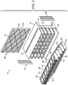
FIG. 2 is a schematic, exploded view of the filter assembly portion ofFIG. 1 ; -
FIG. 3 is a schematic, perspective view of a single centrifugal unit illustrating the top, front and side view exhibiting the intake portion and the filter tank portion; -
FIG. 4 is a schematic, perspective view of the centrifugal unit ofFIG. 3 , exhibiting a back wall of the filter tank and the plurality of orifices therein permitting the at least partially cleaned air to exit the centrifugal filter unit; and -
FIG. 5 is a schematic, perspective view of the single centrifugal unit illustrating the bottom, front and side view ofFIG. 3 . - The present invention is described with reference to the attached figures, wherein like reference numerals are used throughout the figures to designate similar or equivalent elements. The figures are not drawn to scale and they are provided merely to illustrate the instant invention. Several aspects of the invention are described below with reference to example applications for illustration. It should be understood that numerous specific details, relationships, and methods are set forth to provide a full understanding of the invention. One having ordinary skill in the relevant art, however, will readily recognize that the invention can be practiced without one or more of the specific details or with other methods. In other instances, well-known structures or operations are not shown in detail to avoid obscuring the invention. The present invention is not limited by the illustrated ordering of acts or events, as some acts may occur in different orders and/or concurrently with other acts or events. Furthermore, not all illustrated acts or events are required to implement a methodology in accordance with the present invention.
- Shown at 10 in
FIG. 1 is the combination of aserver 12 and its attachedfilter assembly 14.FIG. 2 shows an exploded view of thefilter assembly 14 ofFIG. 1 .Server 12 can be a rack server configured to be received in a slot of a rack (not shown). However, the various embodiments are not limited in this regard. Rather thefilter assembly 14 can be used with other types of computing devices. Although aserver 12 is exemplary of the type of electronic component to which thefilter assembly 14 may be employed in combination, it is to be understood that other electronic components, other than a server, may be used in combination withfilter assembly 14. Such other electronic components could include storage, switch and similar electrical systems. As shown inFIGs. 1 and2 ,Filter assembly 14 comprises areplaceable surface filter 15 according to a first embodiment. Server 12 (the internal components thereof not being illustrated) comprises ahousing 13 upon whichfilter assembly 14 is mounted. A pair ofelastic strips 16, 17 (best seen in the exploded view ofFIG. 2 ), are positioned between thefilter assembly 14 and theserver 12 to permit access to input/output electrical sockets (not shown) in theserver 12. In an alternative embodiment, only one elastic strip could be used, provided that it can extend down (or up) both side surfaces occupied byelastic strips server 12 to peripheral equipment (not shown) or electrical connections (including internet access) associated withserver 12. Thus, cables (not shown) could be connected to the server and exit beneath theelastic strips elastic strips -
FIG. 2 is an exploded view of thefilter assembly 14 ofFIG. 1 .Filter assembly 14 comprises a lattice support orframework 18. The lattice support orframework 18 can be formed of metal, plastic, or a composite of metal and plastic. As the plastic, any of the moldable polymers, copolymers, terpolymers, or blends of polyethylene, polypropylene, polystyrene, polyvinylchloride, polyacrylates, epoxies and rubbery polymers, and acrylonitiles, could be employed to form lattice support orframework 18. The polyacrylates include ethyl methacrylate and methyl methacrylate, among others. The acrylonitriles include terpolymers such as acrylonitrile butadiene styrene ("ABS"). Preferably these plastics are reinforced with fillers including carbon black, and preferably including fibers, particularly carbon or graphite fibers, to prevent the build-up of a static electrical charge to attract dust particles. Alternatively, the plastic could be coated with a dust repelling coating, such as polytetrafluoroethylene, to reduce dust build-up on thelattice support 18. These polymers can be easily fabricated by injection molding, as well as by 3-D (three-dimensional) printing. Composites of polymer and metal, as well as filled or fiber-reinforced polymer, provide the most strength, although engineering polymers with enhanced impact resistance could be used without fiber-reinforcement and still yield exceptional strength. -
Lattice support 18 defines anaperture 19 therein, into which anextended surface filter 20 can be inserted.Filter 20 permits air or other coolant gas to flow there- through into the inlet orifice(s) (not shown) ofserver 12.Filter 20 can mechanically entrain particulates in the coolant gas, or can be treated so as to also attract and retain particulates by reason of electrostatic forces.Filter 20 comprises afilter medium 21. -
Filter medium 21 can comprise a porous structure, such as a fabric or blanket of woven or non-woven fibers, foamed polymer, or ceramic or other porous structure that will permit the coolant gas to penetrate, but has channels which will filter out particulates in the coolant gas. The material of the woven or non-woven fabric or blanket is not particularly limited, and polyolefins (polyethylene, polypropylene, or the like) polyamide, polyester (such as PET- Polyethylene Terephthalate), aromatic polyamide, polyacrylonitrile, polyvinylidene fluoride, polyvinyl alcohol (PVA), polyurethane, or a composite material of the foregoing, could be employed as thefilter medium 21. Additionally, fibrillated membranes of polytetrafluoroethylene (PTFE), either as a homopolymer, or as a modified copolymer, can also be mixed in with any of the foregoing fibers as part offilter medium 21. - A
reticulated framework 22, as well as anouter frame 23, supports filter medium 21.Filter 20 can also be a High Efficiency Particulate Accumulator ("HEPA") filter. The HEPA filter can capture many bacteria, viruses, allergens (such as pollens, spores, smoke, etc.), and other relatively small organisms or particles, including nano-particles, that can be found in ambient air. In addition, it is possible to also include as part offilter 20, a component that will remove volatile organic compounds ("VOC"), e.g., certain chemicals, gases, etc., and odors from ambient air. This filter to remove VOCs can be combined as a separate layer on thereplaceable surface filter 20 or, in some instances, can be a separate, stand-alone third filter, placed downstream of thereplaceable surface filter 20. This additional layer or separate third filter may be a charcoal filter. - In order to extend the service life of
filter medium 21, the number of particulates reaching thefilter 20 should be minimized as much as possible. Accordingly, the disclosure contemplates providing a pre-filter assembly. This pre-filter assembly can be formed using a plurality of centrifugal force filtering elements. For example, as shown inFIG. 1 , the pre-filtering units are arranged in several rows, with a plurality of pre-filters in each row. Although it might be envisioned to employ a single pre-filter to service the entire intake area, only one pre-filter would be too big to service the full intake area, multiple units can minimize the volume of the filter assembly. - As shown in the embodiment of
FIG. 2 , the pre-filter assembly can include a plurality of centrifugalforce filtering units row 31. Other centrifugal force filtering units can be arranged inrows FIG. 2 ,row 31 will nest and interfit intolattice space 41;row 32 will nest and interfit intolattice space 42; and so on, respectively, throughrow 35 fitting intolattice space 45 until theentire intake surface 46 offilter assembly 14 is occupied by the centrifugal filtering units. A screen orlatticework 47 can be placed in front of an intake or entry port of the individual centrifugal force units 24-30. - The structure of an individual centrifugal force unit, for example centrifugal
force filtering unit 24, is shown in enlarged detail inFIGs. 3, 4 and5 . Each centrifugal unit comprises anintake 50 into which flowscoolant gas 52 containing entrained particulates (not shown). Impinging onprimary surface 53 ofcentrifugal force unit 24, the flow ofgas 52 abruptly changes direction and is directed in a turbulent flow throughentry port 54 so as to tangentially impinge uponinner wall 55 ofcentrifugal unit 24.Inner wall 55 imparts a cyclonic flow of thecoolant gas 52, carrying entrained particles throughexit port 64 ofcentrifugal unit 24. The entrained particles normally have a higher specific gravity than the coolant gas and are thereby directed along theinner wall 55.Exit port 64 is smaller in area than entry port 54 (best shown inFIG. 4 ), such that some of the coolant gas continues to flow againstinner wall 55 reinforcing the cyclonic flow of newly entering gas intocentrifugal force unit 24, while most of the entrained particulates are forced throughexit port 64. The pressure drop thoughcentrifugal force unit 24 fromentry port 54 throughexit port 64, and beyond, is created by the fan(s) (not shown) ofserver 12, normally provided for introducing coolant gas to reduce the temperature of theserver 12. This pressure drop accelerates the flow of the coolant gas when in thecentrifugal force unit 24. In this embodiment, thecentrifugal force unit 24 has no moving parts and is therefore termed a "static" centrifugal force unit. Upon exit of the cyclonic flow throughexit port 64 ofcentrifugal force unit 24 the gas, with entrained particulates contained therein are directed to filtertank 57. - Within
filter tank 57, can be placed a second filtering medium, such as a plurality of elongated fibers or another porous material (such as a woven fabric, a non-woven fabric blanket, a polymer, or a ceramic foam)., The purpose the second filtering medium is to capture at least some, preferably the majority and most preferably, most of the particulates entrained in the coolant gas enteringentry port 54 ofcentrifugal unit 24. The fibers that can be employed withinfiber tank 57 can include those described above for use infilter medium 21. The particulate depletedexit gas 62 exits thefilter tank 57 through a plurality of orifices, shown generally at 58, in awall 59 of fiber tank 57 (best illustrated inFIG. 4 ). Thewall 59 is preferably the rear wall ofcentrifugal unit 24 and facesreplaceable filter 20, such than any existing particulate in the particulate depleted exit gas impinges directly ontofilter medium 21 offilter 20. Any centrifugal force unit in addition to centrifugal force unit 24 (for example, any of centrifugal force units 25-30) could operate in the same fashion described in detail with regard tocentrifugal unit 24. Some of the coolant gas may be directed into the central opening ofcentrifugal unit 24 and exit beneath the unit 24 (as shown in the bottom view ofFIG. 5 ). While, the coolant gas has been described as typically comprising air, the embodiments described herein are also applicable to an oxygen enriched, or oxygen deficient, atmosphere as well. It is understood that should the static centrifugal force units described herein not be sufficiently powered by the pressure drop caused by the cooling fan(s) of theserver 12, then additional fan(s) (not shown) could be provided withinfilter assembly 14 in a position downstream offilter 20, or upstream offilter 20, but downstream ofentry port 54. Alternatively, the static centrifugal force filtering units could be turned into dynamic centrifugal force filtering units by providing an impeller within the centrifugal force unit to create the cyclonic flow. - The pre-filtering array of centrifugal force units and replaceable surface filter may be fitted as OEM equipment onto new servers at the factory, or may take the form of an accessory to be retrofit to existing servers. The apparatus provides, in combination, a flow through filter as well as a pre-filter that operates by centrifugal force to remove entrained particulates from a moving coolant stream before the coolant gas enters the server.
- Although the invention has been illustrated and described with respect to one or more implementations, equivalent alterations and modifications will occur to others skilled in the art upon the reading and understanding of this specification and the annexed drawings. In addition, while a particular feature of the invention may have been disclosed with respect to only one of several implementations, such feature may be combined with one or more other features of the other implementations as may be desired and advantageous for any given or particular application.
Claims (15)
- A filter unit (14) for a server (12) chassis, the filtering unit (14) comprising:a lattice support (18) defining a plurality or rows (31, 32, 33, 34, 35) into which rows can be inserted a centrifugal force creating unit;the lattice support (18) also defining an aperture (19) for receiving a replaceable surface filter (20);the replaceable surface filter (20);a plurality of centrifugal force filter units (24, 25, 26, 27, 28, 29, 30) in combination with the lattice (18), the centrifugal force filter units (24, 25, 26, 27, 28, 29, 30) positioned upstream of the flow through filter; and,at least one elastic strip (16,17) for positioning between the filter unit (14) and a server (12).
- The filter unit (14) of claim 1, wherein the centrifugal force units (24, 25, 26, 27, 28, 29, 30) each comprises:an intake (50);a wall (53) changing the direction of flow of an incoming particulate-containing coolant gas (52) entering the intake (50), the wall (53) terminating in an entry port (54);the entry port (54) shaped and positioned to impact the particulate-containing gas (52) upon an arcuate surface (55); andthe arcuate surface (55) defining an exit port (64).
- The filter unit (14) of claim 2, wherein the total area of the exit port (64) is less than the total area of the entry port (54).
- The filter unit (14) of claim 2, further comprising a fiber tank (57) adjacent the exit port (64).
- The filter unit (14) of claim 4, further comprising fibers in the fiber tank (57) that act as a filter associated with each of the plurality of centrifugal force units (24, 25, 26, 27, 28, 29, 30).
- The filter unit (14) of claim 1, wherein at least one of the plurality of centrifugal force units (24, 25, 26, 27, 28, 29, 30) is a static centrifugal force unit.
- The filter unit (14) of claim 1, wherein the fibers in the fiber tank (57) are at least one selected from the group consisting of polyethylene, polypropylene, polyamide, polyester, aromatic polyamide, polyvinylidene fluoride, polyvinyl alcohol, polyurethane, fibrillated polytetrafluoroethylene, or a composite material consisting of at least two of the foregoing fibers.
- The filter unit (14) of claim 1, wherein the lattice support (18) comprises a material which is at least one selected from the group consisting of plastic, metal, and composites.
- The filter unit (14) of claim 1, wherein the at least one elastic strip (16, 17) is sized and shaped to permit cable passage between the server (12) and peripheral equipment.
- A combination comprising a server (12) and the filter unit (14) of claim 1.
- A method of reducing the amount of particulates entering into a server (12) from a particulate- containing coolant gas (52), the method comprising:passing the particulate-containing coolant gas (52) through a centrifugal force filter unit (24, 25, 26, 27, 28, 29, 30) to remove at least some particulates contained in the coolant gas (52) to obtain a particulate reduced coolant gas (62); andthereafter filtering the particulate reduced coolant gas (62) through a replaceable surface filter (20) before introducing the coolant gas (52) into the server (12).
- The method of claim 11, wherein the passing of the coolant gas (52) through a centrifugal force filter unit (24, 25, 26, 27, 28, 29, 30) comprises:impinging the particulate-containing coolant gas (52) upon a wall (53) to change the direction of flow of the coolant gas (52);passing the coolant gas (52) through an entry port (54) and imparting cyclonic flow to the coolant gas (52);removing at least some of the particulates from the particulate-containing coolant gas (52) through an exit port (64) in the centrifugal force filter unit (24, 25, 26, 27, 28, 29, 30); andcapturing some of the particulates in a fiber tank (57) of the centrifugal force filter unit (24, 25, 26, 27, 28, 29, 30).
- The method of claim 12, further comprising passing a particulate-reduced coolant gas (62) from the fiber tank (57) of the centrifugal force filter unit (24, 25, 26, 27, 28, 29, 30) towards the replaceable surface filter (20).
- The method of claim 12, further comprising causing the passing of the particulate-containing coolant gas (52) through the centrifugal force filter unit (24, 25, 26, 27, 28, 29, 30) to occur solely due to the pressure drop created by the cooling fan of the server (12).
- The method of claim 11, wherein the replaceable surface filter (20) is a HEPA filter, and the step of passing the coolant gas (52) through the surface filter (20) comprises removing bacteria, viruses, and allergens from the coolant gas (52).
Applications Claiming Priority (1)
| Application Number | Priority Date | Filing Date | Title |
|---|---|---|---|
| US15/730,937 US10653992B2 (en) | 2017-10-12 | 2017-10-12 | Server dust collector |
Publications (2)
| Publication Number | Publication Date |
|---|---|
| EP3470128A1 true EP3470128A1 (en) | 2019-04-17 |
| EP3470128B1 EP3470128B1 (en) | 2022-01-19 |
Family
ID=61027571
Family Applications (1)
| Application Number | Title | Priority Date | Filing Date |
|---|---|---|---|
| EP18153464.5A Active EP3470128B1 (en) | 2017-10-12 | 2018-01-25 | Server dust collector |
Country Status (5)
| Country | Link |
|---|---|
| US (1) | US10653992B2 (en) |
| EP (1) | EP3470128B1 (en) |
| JP (1) | JP6701252B2 (en) |
| CN (1) | CN109647103B (en) |
| TW (1) | TWI651613B (en) |
Families Citing this family (13)
| Publication number | Priority date | Publication date | Assignee | Title |
|---|---|---|---|---|
| CN114711662B (en) | 2015-07-24 | 2024-07-09 | 恩弗里德系统公司 | Apparatus, method and system for separating particles from air and fluid |
| US20220008851A1 (en) * | 2017-01-23 | 2022-01-13 | Enverid Systems, Inc. | Long life air filter |
| WO2019018788A1 (en) * | 2017-07-20 | 2019-01-24 | Enverid Systems, Inc. | Flow and pressure control in cyclonic filter arrays |
| TWI666047B (en) * | 2018-03-09 | 2019-07-21 | 緯穎科技服務股份有限公司 | Dust collector and electronic system capable of automatically removing dust |
| US10751658B2 (en) * | 2018-04-04 | 2020-08-25 | Cisco Technology, Inc. | External rack mounted filter for network device |
| US10933351B2 (en) * | 2018-04-30 | 2021-03-02 | Bendix Commercial Vehicle Systems Llc | Effluent processing apparatus for a vehicle air brake charging system |
| US10835849B2 (en) * | 2018-06-27 | 2020-11-17 | Particle Recovery, Llc | Sinuous path inertial particle separator system and method |
| US20210291202A1 (en) * | 2018-08-31 | 2021-09-23 | Enverid Systems, Inc. | Systems, devices, and methods for cyclonic filteration |
| WO2021257521A1 (en) * | 2020-06-19 | 2021-12-23 | Noetix Pharma Llc | Filtration apparatus and method |
| KR102912830B1 (en) * | 2020-07-31 | 2026-01-15 | 엘지이노텍 주식회사 | Converter |
| CN112667039B (en) * | 2020-12-16 | 2024-04-09 | 佛山职业技术学院 | Pre-dedusting type chassis |
| US11828230B2 (en) * | 2021-10-04 | 2023-11-28 | General Electric Company | System and method for mitigating particulate intrusion to an air intake system of a gas turbine system with intrusion protective coatings tailored to locale of operation |
| CN115569444A (en) * | 2022-11-14 | 2023-01-06 | 新乡市利菲尔特滤器股份有限公司 | Press-connecting assembly device for filter press-connecting filter screen assembly |
Citations (4)
| Publication number | Priority date | Publication date | Assignee | Title |
|---|---|---|---|---|
| FR2240036A1 (en) * | 1973-08-10 | 1975-03-07 | Alsthom Cgee | Gas filter having no replaceable membrane - using centrifugal action induced by profiled vanes |
| US8591625B2 (en) * | 2011-11-13 | 2013-11-26 | International Business Machines Corporation | Server rack front door with contamination filter and sensor |
| CN203492295U (en) * | 2013-09-30 | 2014-03-19 | 青岛特锐德电气股份有限公司 | Electrical device dustproof casing and electrical device |
| WO2016113001A1 (en) * | 2015-01-14 | 2016-07-21 | Mann+Hummel Gmbh | Housing main part of a filter housing, filter system, and pre-separator module of a filter system |
Family Cites Families (41)
| Publication number | Priority date | Publication date | Assignee | Title |
|---|---|---|---|---|
| LU34342A1 (en) * | 1955-05-26 | |||
| US2907406A (en) * | 1957-01-02 | 1959-10-06 | Donaldson Co Inc | Dry type air cleaner |
| US3155474A (en) * | 1959-11-16 | 1964-11-03 | American Air Filter Co | Dust separator |
| US3903404A (en) * | 1973-10-17 | 1975-09-02 | Amdahl Corp | Computer construction and method |
| US3907671A (en) * | 1974-12-18 | 1975-09-23 | Jr Joseph F Baigas | Separating device |
| US4019883A (en) * | 1975-06-02 | 1977-04-26 | General Motors Corporation | Vortex sulfuric acid separator |
| SE406713B (en) * | 1977-07-18 | 1979-02-26 | Celleco Ab | HYDROCYCLOSE SEPARATOR WITH SLIDES IN THE CIRCULAR CYLINDRICAL PART OF THE SEPARATION CHAMBER |
| US4751872A (en) * | 1987-05-26 | 1988-06-21 | Lawson Jr Theodore J | Ventilation system |
| US5180486A (en) * | 1989-11-28 | 1993-01-19 | Lsr Environmental Systems Company | Potential flow centrifugal separator system for removing solid particulates from a fluid stream |
| US5591253A (en) * | 1995-03-07 | 1997-01-07 | Electric Power Research Institute, Inc. | Electrostatically enhanced separator (EES) |
| US5904755A (en) * | 1996-09-13 | 1999-05-18 | Tornex, Inc. | Furniture having air control functions |
| US6334234B1 (en) * | 1999-01-08 | 2002-01-01 | Fantom Technologies Inc. | Cleaner head for a vacuum cleaner |
| DE10222800B4 (en) * | 2002-05-23 | 2013-06-27 | Mann + Hummel Gmbh | Filter in a filter housing |
| TWM246643U (en) * | 2002-12-06 | 2004-10-11 | Jie Ouyang | Computer fan assembly mechanism having filtering and sterilizing functions |
| US20070081888A1 (en) * | 2003-11-18 | 2007-04-12 | Howard Harrison | Series fans with flow modification element |
| KR100729716B1 (en) * | 2005-10-19 | 2007-06-19 | 삼성광주전자 주식회사 | Vacuum cleaner |
| JP4753847B2 (en) * | 2006-11-29 | 2011-08-24 | シャープ株式会社 | Vacuum cleaner |
| DE202007004476U1 (en) * | 2007-03-23 | 2008-07-31 | Mann+Hummel Gmbh | Filter for cleaning a fluid |
| US9492773B2 (en) * | 2008-02-26 | 2016-11-15 | Mann+Hummel Gmbh | Filter device, especially an air filter |
| US8926724B2 (en) * | 2008-02-26 | 2015-01-06 | Mann + Hummel Gmbh | Filtering device, in particular air filter |
| US7883558B2 (en) * | 2008-05-07 | 2011-02-08 | United Technologies Corporation | Electrostatic particulate separation for emission treatment systems |
| FI20085945A7 (en) * | 2008-10-08 | 2010-04-09 | Abb Oy | Electronic device cooling structure and method |
| DE202008017059U1 (en) * | 2008-12-23 | 2010-05-12 | Mann + Hummel Gmbh | Filter device for internal combustion engines |
| AU2010214785B2 (en) * | 2009-09-10 | 2014-06-12 | Bissell Inc. | Extraction cleaner and centrifugal air/water separator therefor |
| DE102010045669A1 (en) * | 2009-10-12 | 2011-04-21 | Mann+Hummel Gmbh | filter means |
| US9222680B1 (en) * | 2009-11-20 | 2015-12-29 | Vent-A-Hood, Ltd. | Duct-free cooking air filtration systems and methods |
| JP5443230B2 (en) * | 2010-03-25 | 2014-03-19 | ニッタ株式会社 | Fan filter unit |
| US8701821B2 (en) * | 2010-03-29 | 2014-04-22 | David O'Coimin | Acoustic dampening sleeve for electronic equipment and method of making the same |
| DE102010014278A1 (en) * | 2010-04-08 | 2011-10-13 | Mann + Hummel Gmbh | cyclone |
| DE102011011595A1 (en) * | 2011-02-17 | 2012-08-23 | Mann + Hummel Gmbh | filter element |
| KR20120111338A (en) * | 2011-03-31 | 2012-10-10 | 삼성전자주식회사 | Dust collecting structure for air-cooling electric appratus and electric appratus having the same |
| CN102999116B (en) * | 2011-09-08 | 2015-06-17 | 英业达股份有限公司 | server rack |
| US20150077935A1 (en) * | 2013-09-13 | 2015-03-19 | Anue Systems, Inc. | Air Filter And Cable Management Assemblies For Network Communication Systems |
| CN104023509B (en) * | 2014-06-27 | 2017-01-18 | 北京博悦能工程技术有限公司 | Server cabinet |
| US20160067719A1 (en) * | 2014-09-08 | 2016-03-10 | Ivo Fill | Hybrid cyclone mist collector |
| CN114711662B (en) * | 2015-07-24 | 2024-07-09 | 恩弗里德系统公司 | Apparatus, method and system for separating particles from air and fluid |
| JP2017023984A (en) * | 2015-07-28 | 2017-02-02 | パナソニックIpマネジメント株式会社 | Dust collector and management cabinet equipped with it |
| CN204929470U (en) * | 2015-09-28 | 2015-12-30 | 宁波市岭登电器有限公司 | System control cabinet |
| CN205026810U (en) * | 2015-10-09 | 2016-02-10 | 镇江香江云动力科技有限公司 | Data center refrigerating module with intelligence direction air supply function |
| US20180207573A1 (en) * | 2017-01-23 | 2018-07-26 | Enverid Systems, Inc. | Long life filter |
| US10893632B2 (en) * | 2017-05-12 | 2021-01-12 | Diversified Control, Inc. | Equipment enclosure free-air cooling assembly with indexing pre-screen |
-
2017
- 2017-10-12 US US15/730,937 patent/US10653992B2/en active Active
- 2017-12-14 TW TW106144001A patent/TWI651613B/en active
-
2018
- 2018-01-02 CN CN201810001010.5A patent/CN109647103B/en active Active
- 2018-01-25 EP EP18153464.5A patent/EP3470128B1/en active Active
- 2018-03-22 JP JP2018054321A patent/JP6701252B2/en active Active
Patent Citations (4)
| Publication number | Priority date | Publication date | Assignee | Title |
|---|---|---|---|---|
| FR2240036A1 (en) * | 1973-08-10 | 1975-03-07 | Alsthom Cgee | Gas filter having no replaceable membrane - using centrifugal action induced by profiled vanes |
| US8591625B2 (en) * | 2011-11-13 | 2013-11-26 | International Business Machines Corporation | Server rack front door with contamination filter and sensor |
| CN203492295U (en) * | 2013-09-30 | 2014-03-19 | 青岛特锐德电气股份有限公司 | Electrical device dustproof casing and electrical device |
| WO2016113001A1 (en) * | 2015-01-14 | 2016-07-21 | Mann+Hummel Gmbh | Housing main part of a filter housing, filter system, and pre-separator module of a filter system |
Also Published As
| Publication number | Publication date |
|---|---|
| JP6701252B2 (en) | 2020-05-27 |
| CN109647103B (en) | 2021-08-13 |
| US10653992B2 (en) | 2020-05-19 |
| TWI651613B (en) | 2019-02-21 |
| TW201915652A (en) | 2019-04-16 |
| CN109647103A (en) | 2019-04-19 |
| JP2019072709A (en) | 2019-05-16 |
| EP3470128B1 (en) | 2022-01-19 |
| US20190111375A1 (en) | 2019-04-18 |
Similar Documents
| Publication | Publication Date | Title |
|---|---|---|
| US10653992B2 (en) | Server dust collector | |
| US4737173A (en) | Room air treatment system | |
| CN101223838B (en) | Fan cooling unit for cooling electronic components | |
| RU2606980C2 (en) | Filter without zigzag filtering panels for places of livestock management | |
| US10575495B2 (en) | Method and system for monitoring air flow impurity | |
| WO1995033570A1 (en) | Electrostatic fibrous filter | |
| WO1995033570A9 (en) | Electrostatic fibrous filter | |
| US10926209B1 (en) | Air filtration system, air filtration device, and air filtration module for use therewith | |
| WO2014058692A9 (en) | Improved v-panel filter | |
| US20120198804A1 (en) | HVAC Air Filter with Peel Layers | |
| CN106457113B (en) | Synthetic Injected Hydrophilic Filter System | |
| US6758884B2 (en) | Air filtration system using point ionization sources | |
| US20230175717A1 (en) | Air filtration for livestock | |
| CA3101445C (en) | Method and system for monitoring air flow impurity | |
| JP2013078747A (en) | Dust collector | |
| EP4076700B1 (en) | Pleated filter element for air filter | |
| JP3434587B2 (en) | Filter media for air filter | |
| CN212214919U (en) | Air purifier | |
| US11510391B2 (en) | Method and system for monitoring air flow impurity | |
| DE102009054031A1 (en) | High performance air purifying device has housing and air duct arranged in housing, positively charged dust collector arranged in air duct and electric blower | |
| CN218154474U (en) | Filtering module, air conditioner indoor unit and air conditioning system | |
| WO2021247049A1 (en) | Air filtration system, air filtration device, and air filtration module for use therewith | |
| CN223896195U (en) | Dust-containing type air purifier | |
| CN219897531U (en) | Dry paint mist filter | |
| CN105003977A (en) | Ultra-thin air purification device and air purification device combined with door |
Legal Events
| Date | Code | Title | Description |
|---|---|---|---|
| PUAI | Public reference made under article 153(3) epc to a published international application that has entered the european phase |
Free format text: ORIGINAL CODE: 0009012 |
|
| STAA | Information on the status of an ep patent application or granted ep patent |
Free format text: STATUS: THE APPLICATION HAS BEEN PUBLISHED |
|
| AK | Designated contracting states |
Kind code of ref document: A1 Designated state(s): AL AT BE BG CH CY CZ DE DK EE ES FI FR GB GR HR HU IE IS IT LI LT LU LV MC MK MT NL NO PL PT RO RS SE SI SK SM TR |
|
| AX | Request for extension of the european patent |
Extension state: BA ME |
|
| STAA | Information on the status of an ep patent application or granted ep patent |
Free format text: STATUS: REQUEST FOR EXAMINATION WAS MADE |
|
| 17P | Request for examination filed |
Effective date: 20190523 |
|
| RBV | Designated contracting states (corrected) |
Designated state(s): AL AT BE BG CH CY CZ DE DK EE ES FI FR GB GR HR HU IE IS IT LI LT LU LV MC MK MT NL NO PL PT RO RS SE SI SK SM TR |
|
| STAA | Information on the status of an ep patent application or granted ep patent |
Free format text: STATUS: EXAMINATION IS IN PROGRESS |
|
| 17Q | First examination report despatched |
Effective date: 20200612 |
|
| GRAP | Despatch of communication of intention to grant a patent |
Free format text: ORIGINAL CODE: EPIDOSNIGR1 |
|
| STAA | Information on the status of an ep patent application or granted ep patent |
Free format text: STATUS: GRANT OF PATENT IS INTENDED |
|
| INTG | Intention to grant announced |
Effective date: 20210915 |
|
| GRAS | Grant fee paid |
Free format text: ORIGINAL CODE: EPIDOSNIGR3 |
|
| GRAA | (expected) grant |
Free format text: ORIGINAL CODE: 0009210 |
|
| STAA | Information on the status of an ep patent application or granted ep patent |
Free format text: STATUS: THE PATENT HAS BEEN GRANTED |
|
| AK | Designated contracting states |
Kind code of ref document: B1 Designated state(s): AL AT BE BG CH CY CZ DE DK EE ES FI FR GB GR HR HU IE IS IT LI LT LU LV MC MK MT NL NO PL PT RO RS SE SI SK SM TR |
|
| REG | Reference to a national code |
Ref country code: GB Ref legal event code: FG4D |
|
| REG | Reference to a national code |
Ref country code: CH Ref legal event code: EP |
|
| REG | Reference to a national code |
Ref country code: DE Ref legal event code: R096 Ref document number: 602018029682 Country of ref document: DE |
|
| REG | Reference to a national code |
Ref country code: AT Ref legal event code: REF Ref document number: 1463458 Country of ref document: AT Kind code of ref document: T Effective date: 20220215 |
|
| REG | Reference to a national code |
Ref country code: IE Ref legal event code: FG4D |
|
| REG | Reference to a national code |
Ref country code: LT Ref legal event code: MG9D |
|
| REG | Reference to a national code |
Ref country code: NL Ref legal event code: MP Effective date: 20220119 |
|
| REG | Reference to a national code |
Ref country code: AT Ref legal event code: MK05 Ref document number: 1463458 Country of ref document: AT Kind code of ref document: T Effective date: 20220119 |
|
| PG25 | Lapsed in a contracting state [announced via postgrant information from national office to epo] |
Ref country code: NL Free format text: LAPSE BECAUSE OF FAILURE TO SUBMIT A TRANSLATION OF THE DESCRIPTION OR TO PAY THE FEE WITHIN THE PRESCRIBED TIME-LIMIT Effective date: 20220119 |
|
| PG25 | Lapsed in a contracting state [announced via postgrant information from national office to epo] |
Ref country code: SE Free format text: LAPSE BECAUSE OF FAILURE TO SUBMIT A TRANSLATION OF THE DESCRIPTION OR TO PAY THE FEE WITHIN THE PRESCRIBED TIME-LIMIT Effective date: 20220119 Ref country code: RS Free format text: LAPSE BECAUSE OF FAILURE TO SUBMIT A TRANSLATION OF THE DESCRIPTION OR TO PAY THE FEE WITHIN THE PRESCRIBED TIME-LIMIT Effective date: 20220119 Ref country code: PT Free format text: LAPSE BECAUSE OF FAILURE TO SUBMIT A TRANSLATION OF THE DESCRIPTION OR TO PAY THE FEE WITHIN THE PRESCRIBED TIME-LIMIT Effective date: 20220519 Ref country code: NO Free format text: LAPSE BECAUSE OF FAILURE TO SUBMIT A TRANSLATION OF THE DESCRIPTION OR TO PAY THE FEE WITHIN THE PRESCRIBED TIME-LIMIT Effective date: 20220419 Ref country code: LT Free format text: LAPSE BECAUSE OF FAILURE TO SUBMIT A TRANSLATION OF THE DESCRIPTION OR TO PAY THE FEE WITHIN THE PRESCRIBED TIME-LIMIT Effective date: 20220119 Ref country code: HR Free format text: LAPSE BECAUSE OF FAILURE TO SUBMIT A TRANSLATION OF THE DESCRIPTION OR TO PAY THE FEE WITHIN THE PRESCRIBED TIME-LIMIT Effective date: 20220119 Ref country code: ES Free format text: LAPSE BECAUSE OF FAILURE TO SUBMIT A TRANSLATION OF THE DESCRIPTION OR TO PAY THE FEE WITHIN THE PRESCRIBED TIME-LIMIT Effective date: 20220119 Ref country code: BG Free format text: LAPSE BECAUSE OF FAILURE TO SUBMIT A TRANSLATION OF THE DESCRIPTION OR TO PAY THE FEE WITHIN THE PRESCRIBED TIME-LIMIT Effective date: 20220419 |
|
| PG25 | Lapsed in a contracting state [announced via postgrant information from national office to epo] |
Ref country code: PL Free format text: LAPSE BECAUSE OF FAILURE TO SUBMIT A TRANSLATION OF THE DESCRIPTION OR TO PAY THE FEE WITHIN THE PRESCRIBED TIME-LIMIT Effective date: 20220119 Ref country code: LV Free format text: LAPSE BECAUSE OF FAILURE TO SUBMIT A TRANSLATION OF THE DESCRIPTION OR TO PAY THE FEE WITHIN THE PRESCRIBED TIME-LIMIT Effective date: 20220119 Ref country code: GR Free format text: LAPSE BECAUSE OF FAILURE TO SUBMIT A TRANSLATION OF THE DESCRIPTION OR TO PAY THE FEE WITHIN THE PRESCRIBED TIME-LIMIT Effective date: 20220420 Ref country code: FI Free format text: LAPSE BECAUSE OF FAILURE TO SUBMIT A TRANSLATION OF THE DESCRIPTION OR TO PAY THE FEE WITHIN THE PRESCRIBED TIME-LIMIT Effective date: 20220119 Ref country code: AT Free format text: LAPSE BECAUSE OF FAILURE TO SUBMIT A TRANSLATION OF THE DESCRIPTION OR TO PAY THE FEE WITHIN THE PRESCRIBED TIME-LIMIT Effective date: 20220119 |
|
| REG | Reference to a national code |
Ref country code: CH Ref legal event code: PL |
|
| PG25 | Lapsed in a contracting state [announced via postgrant information from national office to epo] |
Ref country code: IS Free format text: LAPSE BECAUSE OF FAILURE TO SUBMIT A TRANSLATION OF THE DESCRIPTION OR TO PAY THE FEE WITHIN THE PRESCRIBED TIME-LIMIT Effective date: 20220519 |
|
| REG | Reference to a national code |
Ref country code: BE Ref legal event code: MM Effective date: 20220131 |
|
| REG | Reference to a national code |
Ref country code: DE Ref legal event code: R097 Ref document number: 602018029682 Country of ref document: DE |
|
| PG25 | Lapsed in a contracting state [announced via postgrant information from national office to epo] |
Ref country code: SM Free format text: LAPSE BECAUSE OF FAILURE TO SUBMIT A TRANSLATION OF THE DESCRIPTION OR TO PAY THE FEE WITHIN THE PRESCRIBED TIME-LIMIT Effective date: 20220119 Ref country code: SK Free format text: LAPSE BECAUSE OF FAILURE TO SUBMIT A TRANSLATION OF THE DESCRIPTION OR TO PAY THE FEE WITHIN THE PRESCRIBED TIME-LIMIT Effective date: 20220119 Ref country code: RO Free format text: LAPSE BECAUSE OF FAILURE TO SUBMIT A TRANSLATION OF THE DESCRIPTION OR TO PAY THE FEE WITHIN THE PRESCRIBED TIME-LIMIT Effective date: 20220119 Ref country code: LU Free format text: LAPSE BECAUSE OF NON-PAYMENT OF DUE FEES Effective date: 20220125 Ref country code: EE Free format text: LAPSE BECAUSE OF FAILURE TO SUBMIT A TRANSLATION OF THE DESCRIPTION OR TO PAY THE FEE WITHIN THE PRESCRIBED TIME-LIMIT Effective date: 20220119 Ref country code: DK Free format text: LAPSE BECAUSE OF FAILURE TO SUBMIT A TRANSLATION OF THE DESCRIPTION OR TO PAY THE FEE WITHIN THE PRESCRIBED TIME-LIMIT Effective date: 20220119 Ref country code: CZ Free format text: LAPSE BECAUSE OF FAILURE TO SUBMIT A TRANSLATION OF THE DESCRIPTION OR TO PAY THE FEE WITHIN THE PRESCRIBED TIME-LIMIT Effective date: 20220119 |
|
| PLBE | No opposition filed within time limit |
Free format text: ORIGINAL CODE: 0009261 |
|
| STAA | Information on the status of an ep patent application or granted ep patent |
Free format text: STATUS: NO OPPOSITION FILED WITHIN TIME LIMIT |
|
| PG25 | Lapsed in a contracting state [announced via postgrant information from national office to epo] |
Ref country code: BE Free format text: LAPSE BECAUSE OF NON-PAYMENT OF DUE FEES Effective date: 20220131 Ref country code: AL Free format text: LAPSE BECAUSE OF FAILURE TO SUBMIT A TRANSLATION OF THE DESCRIPTION OR TO PAY THE FEE WITHIN THE PRESCRIBED TIME-LIMIT Effective date: 20220119 |
|
| 26N | No opposition filed |
Effective date: 20221020 |
|
| PG25 | Lapsed in a contracting state [announced via postgrant information from national office to epo] |
Ref country code: LI Free format text: LAPSE BECAUSE OF NON-PAYMENT OF DUE FEES Effective date: 20220131 Ref country code: CH Free format text: LAPSE BECAUSE OF NON-PAYMENT OF DUE FEES Effective date: 20220131 |
|
| PG25 | Lapsed in a contracting state [announced via postgrant information from national office to epo] |
Ref country code: IE Free format text: LAPSE BECAUSE OF NON-PAYMENT OF DUE FEES Effective date: 20220125 |
|
| PG25 | Lapsed in a contracting state [announced via postgrant information from national office to epo] |
Ref country code: SI Free format text: LAPSE BECAUSE OF FAILURE TO SUBMIT A TRANSLATION OF THE DESCRIPTION OR TO PAY THE FEE WITHIN THE PRESCRIBED TIME-LIMIT Effective date: 20220119 |
|
| PG25 | Lapsed in a contracting state [announced via postgrant information from national office to epo] |
Ref country code: IT Free format text: LAPSE BECAUSE OF FAILURE TO SUBMIT A TRANSLATION OF THE DESCRIPTION OR TO PAY THE FEE WITHIN THE PRESCRIBED TIME-LIMIT Effective date: 20220119 |
|
| PG25 | Lapsed in a contracting state [announced via postgrant information from national office to epo] |
Ref country code: HU Free format text: LAPSE BECAUSE OF FAILURE TO SUBMIT A TRANSLATION OF THE DESCRIPTION OR TO PAY THE FEE WITHIN THE PRESCRIBED TIME-LIMIT; INVALID AB INITIO Effective date: 20180125 |
|
| PG25 | Lapsed in a contracting state [announced via postgrant information from national office to epo] |
Ref country code: MK Free format text: LAPSE BECAUSE OF FAILURE TO SUBMIT A TRANSLATION OF THE DESCRIPTION OR TO PAY THE FEE WITHIN THE PRESCRIBED TIME-LIMIT Effective date: 20220119 Ref country code: CY Free format text: LAPSE BECAUSE OF FAILURE TO SUBMIT A TRANSLATION OF THE DESCRIPTION OR TO PAY THE FEE WITHIN THE PRESCRIBED TIME-LIMIT Effective date: 20220119 |
|
| PG25 | Lapsed in a contracting state [announced via postgrant information from national office to epo] |
Ref country code: MC Free format text: LAPSE BECAUSE OF FAILURE TO SUBMIT A TRANSLATION OF THE DESCRIPTION OR TO PAY THE FEE WITHIN THE PRESCRIBED TIME-LIMIT Effective date: 20220321 |
|
| PG25 | Lapsed in a contracting state [announced via postgrant information from national office to epo] |
Ref country code: MC Free format text: LAPSE BECAUSE OF FAILURE TO SUBMIT A TRANSLATION OF THE DESCRIPTION OR TO PAY THE FEE WITHIN THE PRESCRIBED TIME-LIMIT Effective date: 20220321 |
|
| PG25 | Lapsed in a contracting state [announced via postgrant information from national office to epo] |
Ref country code: MT Free format text: LAPSE BECAUSE OF FAILURE TO SUBMIT A TRANSLATION OF THE DESCRIPTION OR TO PAY THE FEE WITHIN THE PRESCRIBED TIME-LIMIT Effective date: 20220119 |
|
| PG25 | Lapsed in a contracting state [announced via postgrant information from national office to epo] |
Ref country code: TR Free format text: LAPSE BECAUSE OF FAILURE TO SUBMIT A TRANSLATION OF THE DESCRIPTION OR TO PAY THE FEE WITHIN THE PRESCRIBED TIME-LIMIT Effective date: 20220119 |
|
| PGFP | Annual fee paid to national office [announced via postgrant information from national office to epo] |
Ref country code: GB Payment date: 20251204 Year of fee payment: 9 |
|
| PGFP | Annual fee paid to national office [announced via postgrant information from national office to epo] |
Ref country code: FR Payment date: 20251128 Year of fee payment: 9 |
|
| PGFP | Annual fee paid to national office [announced via postgrant information from national office to epo] |
Ref country code: DE Payment date: 20251203 Year of fee payment: 9 |