EP3470028B1 - Goggle with replaceable lens - Google Patents
Goggle with replaceable lens Download PDFInfo
- Publication number
- EP3470028B1 EP3470028B1 EP18200538.9A EP18200538A EP3470028B1 EP 3470028 B1 EP3470028 B1 EP 3470028B1 EP 18200538 A EP18200538 A EP 18200538A EP 3470028 B1 EP3470028 B1 EP 3470028B1
- Authority
- EP
- European Patent Office
- Prior art keywords
- goggle
- frame
- lens
- lens assembly
- latch
- Prior art date
- Legal status (The legal status is an assumption and is not a legal conclusion. Google has not performed a legal analysis and makes no representation as to the accuracy of the status listed.)
- Active
Links
Images







Classifications
-
- G—PHYSICS
- G02—OPTICS
- G02C—SPECTACLES; SUNGLASSES OR GOGGLES INSOFAR AS THEY HAVE THE SAME FEATURES AS SPECTACLES; CONTACT LENSES
- G02C9/00—Attaching auxiliary optical parts
- G02C9/04—Attaching auxiliary optical parts by fitting over or clamping on
-
- A—HUMAN NECESSITIES
- A61—MEDICAL OR VETERINARY SCIENCE; HYGIENE
- A61F—FILTERS IMPLANTABLE INTO BLOOD VESSELS; PROSTHESES; DEVICES PROVIDING PATENCY TO, OR PREVENTING COLLAPSING OF, TUBULAR STRUCTURES OF THE BODY, e.g. STENTS; ORTHOPAEDIC, NURSING OR CONTRACEPTIVE DEVICES; FOMENTATION; TREATMENT OR PROTECTION OF EYES OR EARS; BANDAGES, DRESSINGS OR ABSORBENT PADS; FIRST-AID KITS
- A61F9/00—Methods or devices for treatment of the eyes; Devices for putting in contact-lenses; Devices to correct squinting; Apparatus to guide the blind; Protective devices for the eyes, carried on the body or in the hand
- A61F9/02—Goggles
- A61F9/025—Special attachment of screens, e.g. hinged, removable; Roll-up protective layers
-
- G—PHYSICS
- G02—OPTICS
- G02C—SPECTACLES; SUNGLASSES OR GOGGLES INSOFAR AS THEY HAVE THE SAME FEATURES AS SPECTACLES; CONTACT LENSES
- G02C3/00—Special supporting arrangements for lens assemblies or monocles
- G02C3/003—Arrangements for fitting and securing to the head in the position of use
-
- A—HUMAN NECESSITIES
- A61—MEDICAL OR VETERINARY SCIENCE; HYGIENE
- A61F—FILTERS IMPLANTABLE INTO BLOOD VESSELS; PROSTHESES; DEVICES PROVIDING PATENCY TO, OR PREVENTING COLLAPSING OF, TUBULAR STRUCTURES OF THE BODY, e.g. STENTS; ORTHOPAEDIC, NURSING OR CONTRACEPTIVE DEVICES; FOMENTATION; TREATMENT OR PROTECTION OF EYES OR EARS; BANDAGES, DRESSINGS OR ABSORBENT PADS; FIRST-AID KITS
- A61F2210/00—Particular material properties of prostheses classified in groups A61F2/00 - A61F2/26 or A61F2/82 or A61F9/00 or A61F11/00 or subgroups thereof
- A61F2210/009—Particular material properties of prostheses classified in groups A61F2/00 - A61F2/26 or A61F2/82 or A61F9/00 or A61F11/00 or subgroups thereof magnetic
-
- A—HUMAN NECESSITIES
- A61—MEDICAL OR VETERINARY SCIENCE; HYGIENE
- A61F—FILTERS IMPLANTABLE INTO BLOOD VESSELS; PROSTHESES; DEVICES PROVIDING PATENCY TO, OR PREVENTING COLLAPSING OF, TUBULAR STRUCTURES OF THE BODY, e.g. STENTS; ORTHOPAEDIC, NURSING OR CONTRACEPTIVE DEVICES; FOMENTATION; TREATMENT OR PROTECTION OF EYES OR EARS; BANDAGES, DRESSINGS OR ABSORBENT PADS; FIRST-AID KITS
- A61F2220/00—Fixations or connections for prostheses classified in groups A61F2/00 - A61F2/26 or A61F2/82 or A61F9/00 or A61F11/00 or subgroups thereof
- A61F2220/0025—Connections or couplings between prosthetic parts, e.g. between modular parts; Connecting elements
-
- A—HUMAN NECESSITIES
- A61—MEDICAL OR VETERINARY SCIENCE; HYGIENE
- A61F—FILTERS IMPLANTABLE INTO BLOOD VESSELS; PROSTHESES; DEVICES PROVIDING PATENCY TO, OR PREVENTING COLLAPSING OF, TUBULAR STRUCTURES OF THE BODY, e.g. STENTS; ORTHOPAEDIC, NURSING OR CONTRACEPTIVE DEVICES; FOMENTATION; TREATMENT OR PROTECTION OF EYES OR EARS; BANDAGES, DRESSINGS OR ABSORBENT PADS; FIRST-AID KITS
- A61F9/00—Methods or devices for treatment of the eyes; Devices for putting in contact-lenses; Devices to correct squinting; Apparatus to guide the blind; Protective devices for the eyes, carried on the body or in the hand
- A61F9/02—Goggles
- A61F9/026—Paddings; Cushions; Fittings to the face
-
- A—HUMAN NECESSITIES
- A61—MEDICAL OR VETERINARY SCIENCE; HYGIENE
- A61F—FILTERS IMPLANTABLE INTO BLOOD VESSELS; PROSTHESES; DEVICES PROVIDING PATENCY TO, OR PREVENTING COLLAPSING OF, TUBULAR STRUCTURES OF THE BODY, e.g. STENTS; ORTHOPAEDIC, NURSING OR CONTRACEPTIVE DEVICES; FOMENTATION; TREATMENT OR PROTECTION OF EYES OR EARS; BANDAGES, DRESSINGS OR ABSORBENT PADS; FIRST-AID KITS
- A61F9/00—Methods or devices for treatment of the eyes; Devices for putting in contact-lenses; Devices to correct squinting; Apparatus to guide the blind; Protective devices for the eyes, carried on the body or in the hand
- A61F9/02—Goggles
- A61F9/027—Straps; Buckles; Attachment of headbands
-
- G—PHYSICS
- G02—OPTICS
- G02C—SPECTACLES; SUNGLASSES OR GOGGLES INSOFAR AS THEY HAVE THE SAME FEATURES AS SPECTACLES; CONTACT LENSES
- G02C2200/00—Generic mechanical aspects applicable to one or more of the groups G02C1/00 - G02C5/00 and G02C9/00 - G02C13/00 and their subgroups
- G02C2200/02—Magnetic means
-
- G—PHYSICS
- G02—OPTICS
- G02C—SPECTACLES; SUNGLASSES OR GOGGLES INSOFAR AS THEY HAVE THE SAME FEATURES AS SPECTACLES; CONTACT LENSES
- G02C2200/00—Generic mechanical aspects applicable to one or more of the groups G02C1/00 - G02C5/00 and G02C9/00 - G02C13/00 and their subgroups
- G02C2200/06—Locking elements
-
- G—PHYSICS
- G02—OPTICS
- G02C—SPECTACLES; SUNGLASSES OR GOGGLES INSOFAR AS THEY HAVE THE SAME FEATURES AS SPECTACLES; CONTACT LENSES
- G02C2200/00—Generic mechanical aspects applicable to one or more of the groups G02C1/00 - G02C5/00 and G02C9/00 - G02C13/00 and their subgroups
- G02C2200/08—Modular frames, easily exchangeable frame parts and lenses
Definitions
- the latch mechanism may include one or more magnetic elements (e.g., magnets) for securing the lens assembly to the goggle frame.
- the latch mechanism may include at least one actuator for manipulation by the user to release and/or engage the latch, and at least one tab that includes engagement feature(s) which cooperate with respective engagement feature(s) on the actuatable component to engage the latch.
- the actuator may be coupled to the goggle frame or the lens frame. In some embodiments, the actuator is coupled to the goggle frame, for example behind an outrigger so as to at least partially conceal the actuator from view and provide a more aesthetically pleasing look of the goggle.
- an example goggle 100 includes a lens assembly 102 removably coupled to a goggle frame 104.
- the goggle 100 may be of a shield-type design including a single or unitary outer lens 106, which may be configured to extend in the field of view of both the left and right eyes of the user when worn.
- the outer lens 106 may be formed from a single lens blank and may thus be devoid of any seams or other discontinuities in the lens.
- the outer lens 106 may be made from polycarbonate (PC), acrylic, or other materials which can provide suitable optical qualities (e.g., optical clarity) to the optical portion of the eyewear.
- the outer lens 106 may be rimless or frameless in that a perimeter of the lens 106 is not substantially enclosed by a frame, as illustrated in FIG. 1 . These features may provide a larger unobstructed field of view through the outer lens 106.
- the lens assembly 102 may include a spacer 110 (e.g., a foam spacer) that attaches the outer and inner lenses 106, 108 together.
- the spacer 110 may be positioned at least partially between the outer lens 106 and the inner lens 108, and may extend along a peripheral portion of the outer lens 106 and the inner lens 108 so as to provide a large unobstructed field of view through the outer lens 106 and the inner lens 108.
- the spacer 110 may include adhesive on both of its sides (i.e., its front and rear surfaces) to adhere the outer lens 106 to the inner lens 108.
- the spacer 110 may be implemented using a double-sided adhesive foam tape.
- the lens assembly 102 may include a lens frame 112 configured for removably coupling the lens assembly to the goggle frame 104.
- the lens frame 112 may support the inner lens 108 and/or the spacer 110.
- the lens frame 112 may define a seat 114 that receives and supports the spacer 110.
- a rear surface of the spacer 110 may abut against the seat 114 when the lens assembly 102 is assembled, and adhesive applied to the rear surface of the spacer 110 may adhere the spacer 110 to the lens frame 112.
- the lens frame 112 is formed of polycarbonate, and may be molded. The lens frame 112 may thus be relatively more rigid as compared to the relatively softer portions of the goggle frame 104 that are positioned conformally to the user's face.
- the goggle 100 may define a nose recess 120 (e.g., along a bottom periphery of the lens assembly 102), which may be configured to accommodate the nose of the wearer when the goggle 100 is worn.
- a nose pad 122 may be provided at the nose recess 120.
- the nose pad 122 may be formed from a soft or flexible polymeric material (e.g., thermoplastic elastomer (TPE), such as a thermoplastic polyurethane (TPU) material) which may conform to the user's nose for a comfortable fit and may optionally include one or more bendable portions for improved adjustability.
- TPE thermoplastic elastomer
- TPU thermoplastic polyurethane
- the nose pad 122 may form part of the goggle frame 104 (see FIG.
- the nose pad 122 may be removably attached to the lens assembly 102 or the goggle frame 104, such as to enable replacement of the nose pad 122.
- the goggle 100 may include first and second opposite end portions 124-1, 124-2.
- a strap 128 (such as an elastic headband) may be attached to each of the first and second end portions 124-1, 124-2 via first and second outriggers 130-1, 130-2, respectively (see FIGS. 1 and 8 ).
- Each outrigger 130-1, 130-2 may be pivotally coupled to the goggle frame 104 to provide a relatively customized fit of the strap 128 around a front portion of a wearer's head.
- the magnetic materials may be attached to opposing (e.g., facing) sides of the lens assembly 102 and the goggle frame 104 to urge the lens assembly 102 towards the goggle frame 104.
- the magnetic attraction between the magnetic materials on the lens assembly 102 and the goggle frame 104 may provide a centering function (e.g., resulting from the magnetic materials natural tendency to axially align their respective fields to one another), which may facilitate alignment of the lens assembly 102 to the goggle frame 104.
- the goggle frame 104 may include magnetic materials for magnetic coupling with corresponding magnetic materials on the lens assembly 102.
- the goggle frame 104 may include magnets 134 exposed along an angled surface 136 of the goggle frame 104.
- the magnets 134 may be arranged along a lower portion of the goggle frame 104 (such as generally beneath a wearer's eyes and adjacent the wearer's nose) and along an upper portion of the goggle frame 104 (such as adjacent a wearer's forehead).
- Several magnets 134 may be arranged adjacent the nose pad 122.
- the goggle frame 104 includes eight magnets 134, but in other embodiments the goggle frame 104 may include more or less than eight magnets 134.
- the magnets 134 may include an exposed surface that is substantially flush with the angled surface 136, which may be angled inward and rearward toward a center of the goggle frame 104 to facilitate alignment of the lens assembly 102 with the goggle frame 104.
- the magnets 134 may be oriented at about a forty-five degree angle (e.g., forty-five degrees plus or minus thirty degrees) to facilitate alignment of the lens assembly 102 with the goggle frame 104.
- the angled surface 136 and the magnets 134 are oriented at a forty-five degree angle relative to a plane defined by the curvature of the outer lens 106 to facilitate alignment of the lens assembly 102 with the goggle frame 104. In other embodiments, different arrangement (e.g., orientation) of the magnets with respect to the surface 136 may be used.
- the goggle frame 104 may include a face gasket and an interface component for interfacing with the removable lens assembly.
- the face gasket may be provided by one or more resiliently deformable components, which are configured to placed conformally to the user's face.
- the face gasket is provided by a frame ring 140.
- the interface component is implemented as an overmold component or material 142.
- the overmold material 142 may be formed of a relatively hard or rigid material (e.g., nylon) to form an interface component that provides a structural base for interfacing with the lens frame 112.
- the face gasket (e.g., frame ring 140) of the goggle frame 104 may be formed of a softer material (e.g., thermoplastic polyurethane (TPU)) for conformally interfacing with the wearer's face.
- TPU thermoplastic polyurethane
- the frame ring 140 which may be formed from the relatively more flexible material (e.g., TPU) for example by an injection molding process, may be overmolded by the relatively more rigid material (e.g., nylon) in an overmold process during which the interface component is shaped or formed while being joined to the frame ring.
- the interface component(s) may be formed first and the overmolded by the face gasket material.
- the magnets 134 are inserted into pockets 146 defined in the frame ring 140, and then the frame ring 140 is overmolded by the overmold material 142, thereby effectively molding the magnets 134 into the goggle frame 104.
- the magnets 134 may be attached to the frame ring 140, such that the frame ring 140 counteracts the magnetic force imposed on the magnets 134 by the lens assembly 102 to ensure the magnets 134 are not pulled out of the goggle frame 104 during decoupling of the lens assembly 102 from the goggle frame 104. For example, as illustrated in FIG.
- the magnets 134 may include wings 148 extending from opposing ends of the magnets 134, and the wings 148 may be received within slots 150 formed in the frame ring 140 at opposing ends of the pockets 146.
- the overmold material 142 may cover at least a front portion of the frame ring 140 and at least a portion of the magnets 134 to lock the magnets 134 in place (e.g., restrict the wings 148 of the magnets 134 from sliding out of the slots 150 in the frame ring 140). At least a portion of a front surface of the magnets 134 may be exposed through the overmold material 142 to facilitate magnetic coupling of the magnets 134 with the lens assembly 102.
- the lens assembly 102 may include magnetic materials for magnetic coupling with corresponding magnetic materials on the goggle frame 104.
- the lens assembly 102 may include magnets 154 exposed along an angled surface 156 of the lens assembly 102.
- the magnets 154 may be arranged at corresponding locations to the magnets 134 of the goggle frame 104, and may include opposing polarities to the magnets 134 such that the magnets 134, 154 are attracted to each other.
- the magnets 154 may include an exposed surface that is substantially flush with the angled surface 156, which may be angled at a corresponding angle to the angled surface 136 of the goggle frame 104 to facilitate alignment of the lens assembly 102 with the goggle frame 104.
- the magnets 154 may be oriented at about a forty-five degree angle (e.g., forty-five degrees plus or minus thirty degrees) to facilitate alignment of the lens assembly 102 with the goggle frame 104.
- the angled surface 156 and the magnets 154 are oriented at a forty-five degree angle relative to a plane defined by the curvature of the inner lens 108 to facilitate alignment of the lens assembly 102 with the goggle frame 104.
- the magnets 154 may be received in pockets 158 defined in the lens frame 112.
- the magnets 154 may only be inserted into the pockets 158 from a front side of the lens frame 112, such that the lens frame 112 inhibits the magnets 154 from being pulled out of the lens assembly 102 during decoupling of the lens assembly 102 from the goggle frame 104.
- Each latch 180-1, 180-2 may be configured to cause the lever 187 to temporarily move (e.g., pivot) away from the tab 183 during attachment of the lens assembly 102 to the goggle frame 104.
- the lever 187 and/or the tab 183 may include ramp features which may cooperate to cause the lever 187 of each latch 180 to move from its latched position to its unlatched position as the lens assembly 102 is advanced toward the goggle frame 104, e.g., without the application of user force to the lever 187 other than the force applied to advance the lens assembly 102 toward the goggle frame 104.
- the tab 183 need not have a perimeter that defines a regular shape.
- the perimeter of the tab 183 may define any irregular shape as may be suitable for a particular application.
- the tab 183 may be differently shaped in other embodiments than the examples specifically illustrated or described.
- the latch component 186 may include a user-engagement portion 224 and a latch portion 228 as in the illustrated embodiment in FIG. 13 .
- the user-engagement portion 224 may be a generally plate-like structure configured for a wearer to press against to actuate the latch component 186 (e.g., move the lever 187 from its latched position to its unlatched position to enable removal of the lens assembly 102 from the goggle frame 104).
- the latch portion 228 may be angled or rounded at its forward end to define the ramp 204.
- the user-engagement portion 224 may be separated from the latch portion 228 by the fulcrum portion 232, which may define the aperture 231 for receiving the pivot pin or post 190.
- All the user may be required to do is move the lens assembly 102 close to the goggle frame 104, and the magnetic materials of the lens assembly 102 and the goggle frame 104 cooperate with one another to magnetically couple the lens assembly 102 to the goggle frame 104, which movement causes the lever 187 to open and close, thereby securing the lens assembly 102 to the goggle frame 104.
- the extensions 162 and recesses 160 may facilitate the proper alignment and positioning of the lens assembly 102 to the goggle frame 104.
- each outrigger may engage a stop 248 formed on the goggle frame 104 that prevents the outriggers (see outrigger 130-1 in FIG. 11 ) from pivotal movement towards the lever 187, thereby inhibiting the outriggers 130-1, 130-2 from actuating the levers 187.
- the biasing feature may enable the automatic return of the lever 187 to its latched position once the lever 187 has cleared the distal end of the tab 183.
- the wearer may grasp the free end 250 of the lens assembly 102 and move the lens assembly 102 in a lateral direction (see arrow 254 in FIG. 9 ) away from the engaged latch 170-1 to remove the lens assembly 102 from the goggle frame 104.
- moving the lens assembly 102 in the lateral direction allows removal of the tab 183 from behind the lever 187 without actuating the lever 187.
- the lens assembly 102 may be detached from the goggle frame 104 by actuation of only one of the latches 170-1, 170-2.
- the wearer may manually actuate one of the latches 170-1, 170-2 on one side of the goggle 100, pivot the lens assembly 102 about the other, non-actuated latch 170-1, 170-2 on the other side of the goggle 100 until the other latch disengages itself naturally without having to actuate the latch.
- the lens assembly 102 may be pivoted until all of the extensions 162 are removed from the recesses 160 (see FIGS. 2-5 ) and then may be laterally removed from the goggle frame 104.
- the lens assembly 102 is pivoted about twenty to thirty degrees to naturally disengage the other latch. The pivotal range may vary depending on the specific goggle application.
- the near effortless engagement of the lens assembly 102 to the goggle frame 104 in accordance with the present disclosure may enable the user to install and remove the lens assembly 102 without touching the lens surface (that is by only handling the lens assembly 102 by its edges), which may address some shortcomings of existing interchangeable goggle designs.
- the lens assembly 102 may include multiple user engagement features located around a periphery of the lens (e.g., outer lens 106 and/or inner lens 108) for a wearer to grasp during coupling or decoupling of the lens assembly 102 to or from, respectively, the goggle frame 104, thus avoiding touching the lens.
- the lens assembly 102 may include multiple rim portions 256 located around a periphery of the outer lens 106.
- the rim portions 256 may protrude outwardly from the outer lens 106 such that the rim portions 256 form a semi-rimless frame around the periphery of the outer lens 106 for a wearer to grasp during coupling or decoupling of the lens assembly 102 to or from, respectively, the goggle frame 104.
- the rim portions 256 may be located near the corners of the lens assembly 102 to facilitate handling of the lens assembly 102 by the wearer. For example, as illustrated in FIG.
- a first rim portion 256-1 and a fourth rim portion 256-4 may be located at opposing corners of one end- or side-portion of the lens assembly 102, and a second rim portion 256-2 and a third rim portion 256-3 may be located at opposing corners of the other end- or side-portion of the lens assembly 102.
- the wearer may grasp the first and fourth rim portions 256-1, 256-4 and/or the second and third rim portions 256-2, 256-3 to manipulate the lens assembly 102, such as to pivot one end of the lens assembly 102 away from the goggle frame 104 during removal of the lens assembly 102 from the goggle frame 104.
- the rim portions 256 may be formed on the lens frame 112 (see FIG.
- the lens assembly 102 illustrated in FIGS. 1-4 and 14 includes four rim portions 256-1, 256-2, 256-3, 256-4 (generally referred to as rim portions 256), the lens assembly 102 may include more or less than four rim portions.
- the lengths of the rim portions 256 along the periphery of the outer lens 106 may be longer or shorter than the rim portions 256 in the example shown in FIGS. 1-4 .
- FIGS. 16-18 illustrate a retention feature 260 in accordance with further embodiments of the present disclosure.
- the retention feature 260 may include a first latch component (e.g., a gate 262) and a second latch component (e.g., strips 264).
- the gate 262 may include (e.g., be formed at least partially of) a magnetic material (e.g., a permanent magnet such as a rare earth magnet, or ferromagnetic material such as iron or steel).
- Each strip 264 may include a magnet 266 (e.g., a magnetic material such as iron or a neodymium or other type of permanent magnet) affixed thereto, forming magnetic strips 264.
- Each magnet 266 may have the same polarity as each other such that the magnets 266 are configured to repel each other to maintain the strips 264 in a spaced-apart relationship defining a gap 268 therebetween.
- the gate 262 blocks the repelling force of the strips 264, and the magnetic strips 264 are magnetically attracted to the gate 262 (see FIG. 18 ) to secure the lens assembly 102 to the goggle frame 104.
- the second latch component may include a first magnetic strip 264 and the second magnetic strip 264 is built into goggle frame 104.
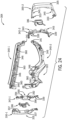
- side portions 342-1 and 342-2 may be coupled to upper frame ring 340-1 and lower frame ring 340-2 by an overmolding process.
- the side portions 342-1 and 342-2 are formed (e.g., by injection molding, compression molding or other suitable molding process or via an additive manufacturing process such as stereolithography (SLA) or other 3D printing process).
- SLA stereolithography
- the side portions are inserted into a mold tool where they are overmolded with the thermoplastic elastomer (e.g., TPU) of the face gasket.
- the magnets may then be inserted into pockets of the frame gasket.
- the face gasket component(s) and the interface component(s) may be each separately formed via a suitable process such as molding or additive manufacturing and the two separately formed components may be attached to one another via an adhesive and/or mechanical coupling (e.g., fasteners, snap features, etc.)
- the partial frame rings 340-1 and 340-2 may include one or more protrusions 341 at end portions 324-1 and 324-2 configured to engage cavities 339 formed in the side portions 342-1 and 342-2.
- the protrusions 341 may have a hook-like structure which may provide additional retention of the side portions 342-1 and 342-2 to the partial frame rings 340-1 and 340-2.
- upper frame ring 340-1 and lower frame ring 340-2 may include holes 331 near end portions 324-1 and 324-2 configured to receive prongs 333 of outriggers 330-1 and 330-2.
- the prongs 333 may retain outriggers 330-1 and 330-2 to the partial frame rings 340-1 and 340-2.
- the prongs 333 may rotate within holes 331, pivotally coupling the outriggers 330-1 and 330-2 to the goggle frame 304.
- the prongs 333 may be configured to engage holes 331 such that the outriggers 330-1 and 330-2 are fixedly attached to the partial frame rings 340-1 and 340-2.
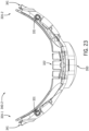
- partial frame rings 340-1 and 340-2 may have angled surfaces 336-1 and 336-2.
- Angled surfaces 336-1 and 336-2 may be angled inward and rearward toward a center of the goggle frame 304 to facilitate alignment of the lens assembly 102 with the goggle frame 304.
- the angled surfaces 336-1 and 336-2 may be oriented at a forty-five degree angle relative to a plane defined by the curvature of the outer lens 106 to facilitate alignment of the lens assembly 102 with the goggle frame 304.
- the angled surfaces 336-1 and 336-2 may define recesses 360.
- the recesses 360 may be positioned and shaped to correspond with extensions 162 of lens assembly 102.
- the goggle frame 304 may include extensions and the lens assembly 102 may include recesses. The corresponding recesses and extensions may facilitate alignment between goggle frame 304 and lens assembly 102.
- goggle frame 304 may include magnetic materials (e.g., magnetic elements) for magnetic coupling with corresponding magnetic materials on the lens assembly 102.
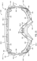
- partial frame rings 340-1 and 340-2 may include magnets 334 exposed along angled surfaces 336-1 and 336-2.
- the magnets 334 may be positioned to correspond to the positions of magnets 154 on lens assembly 102.
- the magnets 334 may have polarities opposite those of magnets 154 to facilitate coupling of lens assembly 102 and goggle frame 304.
- the magnets 334 may have a trapezoidal shape surface.
- Pockets 346 may be defined in the upper and lower frame rings 340-1 and 34-2 along angled surfaces 336-1 and 336-2 between adjacent recesses 360.
- the pockets 346 may have a generally trapezoidal shape oriented such that the opening of the pockets 346 at the angled surfaces 336-1 and 336-2 are smaller than the bottoms of the pockets 346.
- the shape of the pockets 346 may correspond to the trapezoidal shape of the magnets 334 such that the magnets 334 are retained in the pockets 346 and exposed surfaces of the magnets 334 are flush with the angled surfaces 336-1 and 336-2.
- the partial frame rings 340-1 and 340-2 may be temporarily deformed (e.g., bent) such that the opening to the pockets 346 are widened.
- the magnets 334 may be placed inside the pockets 346 during deformation and once the partial frame rings 340-1 and 340-2 are returned to their original shapes, the magnets 334 may be retained within the pockets 346. In some embodiments, an adhesive may be applied inside the pockets 346 to provide additional retention of the magnets 334 in the pockets 346.
- goggle frame 304 is shown including seven magnets 334 in FIG. 21 , it is understood that goggle frame 304 may include more or fewer magnets 334 in other embodiments.
- goggle frame 304 may include additional retention features to secure lens assembly 102 to the goggle frame 304.
- goggle frame 304 may include retention features 370-1 and 370-2 located at side portions 342-1 and 342-2.
- the retention features 370-1 and 370-2 may be at least partially concealed by outriggers 330-1 and 330-2, respectively.
- the retention features 370-1 and 370-2 may comprise latches.
- the goggle 300 may include a first latch 380-1 and second latch 380-2.
- the latches 380-1 and 380-2 may be coupled to or proximate the side portions 342-1 and 342-2, respectively.
- Each latch 380-1 and 380-2 may include a first latch component 184 coupled to the lens assembly 102. That is, portion of the latch included with the lens assembly 102 may be the same as the latch component 184 described in reference to FIGS. 3 and 10-12 in some embodiments (e.g., tab 183).
- Each latch 380-1 and 380-2 may further include a second latch component 186 coupled to the goggle frame 304.
- the second latch component 186 may be the same as the latch component 186 shown in FIGS. 6-11 and 13 in some embodiments. In other embodiments, component 186 may be the same as the latch component 186 illustrated in FIGS. 19A and 19B . In the examples described in reference to FIGS. 20 , 24 and 25 , the latch component 186 of FIGS. 19A and 19B is shown.
- the second latch component 186 of each latch 180-1 and 180-2 may be movably coupled to the goggle frame 104 at side portions 342-1 and 342-2, respectively.
- Side portions 342-1 and 342-2 may each include a post 390.
- the aperture 231 may be configured to receive post 390 pivotally coupling the latch component 186 to the side portion 342.
- the post 390 may restrict movement of the latch component 186 lateral to the post 390.
- the side portion 342 may include lower wall 392 and upper wall 394 on opposite ends of the post 390.
- the lower wall 392 and upper wall 394 may restrict the up and down movement of the latch component 186.
- side portion 342 may include side wall 396 which may restrict pivotal movement of the latch component 186 and/or provide a base for arms 200 to apply a biasing force.
- portions of the partial frame rings 340 may be adjacent to the side wall 396 of the side portion 342.
- a portion of the arms 200 of the latch component 186 may apply a biasing force against the portions of the partial frame rings 340 adjacent to side wall 396.
- side portion 342 may include stops 343.
- stops 343 are in the form of flanges that angle outward from goggle frame 304.
- the outrigger 330 may include recesses 337 having shapes corresponding to stops 343.
- the stops 343 may restrict pivotal movement of outrigger 330 to prevent the outrigger 330 from actuating latch component 186 when the outrigger 330 is pivotally attached.
Landscapes
- Health & Medical Sciences (AREA)
- Ophthalmology & Optometry (AREA)
- Physics & Mathematics (AREA)
- Public Health (AREA)
- Engineering & Computer Science (AREA)
- Biomedical Technology (AREA)
- Heart & Thoracic Surgery (AREA)
- Vascular Medicine (AREA)
- Life Sciences & Earth Sciences (AREA)
- Animal Behavior & Ethology (AREA)
- General Health & Medical Sciences (AREA)
- Veterinary Medicine (AREA)
- Optics & Photonics (AREA)
- General Physics & Mathematics (AREA)
- Eyeglasses (AREA)
- Telescopes (AREA)
Description
- This application claims priority to
U.S. Provisional Application No. 62/572,260 filed October 13, 2017 - Goggles with replaceable lenses typically include a frame and one or more removable lenses. The frame may be equipped with a mechanism for attachment of the lens. In some goggles, the lens is attached to the frame with magnets. However, in existing goggles of this kind, the lens may be easily dislodged from the frame. Additionally or alternatively, in existing goggles, removal of the lens may be unduly complex or cumbersome for a user, or may have other deficiencies which result in a suboptimal user experience. For these reasons or other reasons, improvements in goggles with removable lenses may be desired.
US 2013/104300 discloses a device for detachably fixing a lens on goggles including: a detachable fixing member having a plurality of metal pieces adapted to be insertedly fixed to a plurality of equally spaced insertion grooves formed along a frame rim and a plurality of permanent magnets adapted to be insertedly fixed to a plurality of equally spaced insertion grooves formed along a lens rim on the same line as the plurality of metal pieces insertedly fixed along the frame rim in such a manner as to be coupled and separated to and from the plurality of metal pieces; and clip members adapted to be fixed to both sides of the frame so as to rigidly fix the lens to the frame.US 2014/157496 discloses eyewear, such as a goggle, that can include an anterior module and an interchangeable posterior module. The anterior module can be adapted to support at least one lens in a wearer's field of view. The posterior module can be adapted to fit against a contour of the wearer's face and can be selectively interchangeable with the anterior module to modify at least one physical characteristic of the eyewear - The description will be more fully understood with reference to the following figures in which components may not be drawn to scale, which are presented as various embodiments of the eyewear and eyewear components described herein and should not be construed as a complete depiction of the scope of the present disclosure.
-
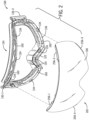
FIG. 1 is an isometric view of a goggle in accordance with some examples of the present disclosure. -
FIG. 2 is a partially exploded front isometric view of the goggle ofFIG. 1 . -
FIG. 3 is a partially exploded rear isometric view of the goggle ofFIG. 1 . -
FIG. 4 is a rear view of a lens assembly of the goggle ofFIG. 1 . -
FIG. 5 is a front view of a goggle frame of the goggle ofFIG. 1 . -
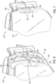
FIG. 6 is a partial front view of the goggle ofFIG. 1 with a right side of a lens assembly spaced from a goggle frame and illustrating movement of the lens assembly when coupling the lens assembly to the goggle frame. -
FIG. 7 is a partial front view of the goggle ofFIG. 6 with the lens assembly being coupled to the goggle frame and illustrating movement of a latch component on the goggle frame when coupling the lens assembly to the goggle frame. -
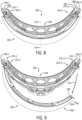
FIG. 8 is a top view of the goggle ofFIG. 1 . -
FIG. 9 is a top view of the goggle ofFIG. 1 illustrating movement of a latch component on the goggle frame and of a lens assembly when decoupling or removing the lens assembly from a goggle frame. -
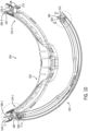
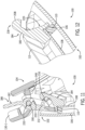
FIG. 10 is a cross-sectional view of the goggle ofFIG. 11 illustrating a latch mechanism of the goggle. -
FIG. 11 is a detail view of the area circumscribed by detail line 11-11 inFIG. 10 , illustrating a latch of the goggle ofFIG. 1 . -
FIG. 12 is a detail view of the area circumscribed by detail line 12-12 inFIG. 10 , illustrating a latch component of a lens assembly of the goggle ofFIG. 1 . -
FIG. 13 is an exploded isometric view of a goggle frame of the goggle ofFIG. 1 . -
FIG. 14 is an exploded isometric view of a lens assembly of the goggle ofFIG. 1 -
FIG. 15 is a cross-sectional view of the goggle ofFIG. 1 taken along sectional line 15-15 inFIG. 8 . -
FIG. 16 is a partial front view of the goggle ofFIG. 1 with a right side of a lens assembly spaced from a goggle frame and illustrating movement of the lens assembly when coupling the lens assembly to the goggle frame in accordance with an alternative latch mechanism of the present disclosure. -
FIG. 17 is a partial rear view of the goggle ofFIG. 16 . -
FIG. 18 is a partial rear view of the goggle ofFIG. 16 with the lens assembly coupled to the goggle frame. -
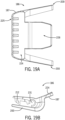
FIG. 19A is a view of a latch component according to another example of the disclosure. -
FIG. 19B is another view of the latch component shown inFIG. 19A . -
FIG. 20 is an isometric view goggle according to another example of the disclosure. -
FIG. 21 is a front view of a portion of a goggle frame of the goggle shown inFIG. 20 . -
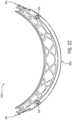
FIG. 22 is a top view of an upper portion of the goggle frame shown inFIG. 21 . -
FIG. 23 is a top view of a lower portion of the goggle frame shown inFIG. 21 . -
FIG. 24 is an exploded view of the goggle frame shown inFIG. 20 . -
FIG. 25 is an isometric side view of side portions and latches of the goggle frame shown inFIG. 24 . - Examples of goggles with removable lenses are described. In some examples, the goggle may include a first retention feature (e.g., magnets) that couple a lens assembly to a goggle frame. To limit inadvertent decoupling of the lens assembly from the goggle frame, the goggle may include a second retention feature (e.g., a latch mechanism) for securing the lens assembly to the goggle frame. In some embodiments, the latch mechanism may include latch components attached to the lens assembly and the goggle frame for securing the lens assembly to the goggle frame. In some embodiments, the latch components may engage mechanically for mechanically securing the lens assembly to the goggle frame. In some embodiments, the latch mechanism may include one or more magnetic elements (e.g., magnets) for securing the lens assembly to the goggle frame. The latch mechanism may include at least one actuator for manipulation by the user to release and/or engage the latch, and at least one tab that includes engagement feature(s) which cooperate with respective engagement feature(s) on the actuatable component to engage the latch. The actuator may be coupled to the goggle frame or the lens frame. In some embodiments, the actuator is coupled to the goggle frame, for example behind an outrigger so as to at least partially conceal the actuator from view and provide a more aesthetically pleasing look of the goggle.
- As shown in
FIG. 1 , anexample goggle 100 includes alens assembly 102 removably coupled to agoggle frame 104. Thegoggle 100 may be of a shield-type design including a single or unitaryouter lens 106, which may be configured to extend in the field of view of both the left and right eyes of the user when worn. Theouter lens 106 may be formed from a single lens blank and may thus be devoid of any seams or other discontinuities in the lens. Theouter lens 106 may be made from polycarbonate (PC), acrylic, or other materials which can provide suitable optical qualities (e.g., optical clarity) to the optical portion of the eyewear. Theouter lens 106 may be rimless or frameless in that a perimeter of thelens 106 is not substantially enclosed by a frame, as illustrated inFIG. 1 . These features may provide a larger unobstructed field of view through theouter lens 106. - In some embodiments, the
lens assembly 102 may include a dual-lens structure. For example, as illustrated inFIG. 14 , thelens assembly 102 may includeouter lens 106 andinner lens 108. Thelenses lenses lenses lenses lenses lenses lenses lenses lenses - Referring still to
FIG. 14 , thelens assembly 102 may include a spacer 110 (e.g., a foam spacer) that attaches the outer andinner lenses spacer 110 may be positioned at least partially between theouter lens 106 and theinner lens 108, and may extend along a peripheral portion of theouter lens 106 and theinner lens 108 so as to provide a large unobstructed field of view through theouter lens 106 and theinner lens 108. Thespacer 110 may include adhesive on both of its sides (i.e., its front and rear surfaces) to adhere theouter lens 106 to theinner lens 108. For example, thespacer 110 may be implemented using a double-sided adhesive foam tape. - With continued reference to
FIG. 14 , thelens assembly 102 may include alens frame 112 configured for removably coupling the lens assembly to thegoggle frame 104. Thelens frame 112 may support theinner lens 108 and/or thespacer 110. As shown in the illustrated embodiment, thelens frame 112 may define aseat 114 that receives and supports thespacer 110. A rear surface of thespacer 110 may abut against theseat 114 when thelens assembly 102 is assembled, and adhesive applied to the rear surface of thespacer 110 may adhere thespacer 110 to thelens frame 112. In some embodiments, thelens frame 112 is formed of polycarbonate, and may be molded. Thelens frame 112 may thus be relatively more rigid as compared to the relatively softer portions of thegoggle frame 104 that are positioned conformally to the user's face. - Referring to
FIGS. 14 and15 , thelens frame 112 may be configured to extend along a peripheral portion of theinner lens 108 to restrict theinner lens 108 from delaminating or separating from thespacer 110. Theinner lens 108 may be formed of a different material than theouter lens 106. For example, theinner lens 108 may be designed to be hydrophilic to inhibit fogging, which may reduce the effectiveness of the adhesive on thespacer 110. To inhibit or reduce the risk of separation of theinner lens 108 and thespacer 110, thelens frame 112 may include alip 116 that extends interiorly from the seat 114 (seeFIG. 14 ). Thelip 116 may abut against arear surface 118 of the inner lens 108 (seeFIG. 15 ) around a periphery of theinner lens 108. With thespacer 110 bonded to theseat 114 of the lens frame 112 (seeFIG. 14 ), theinner lens 108 may be captured or sandwiched between thespacer 110 and thelip 116 of thelens frame 112, thereby inhibiting separation of theinner lens 108 from thespacer 110. As illustrated inFIG. 15 , theinner lens 108 may be smaller in size (e.g., height and/or thickness) than theouter lens 106. - As illustrated in
FIG. 1 , thegoggle 100 may define a nose recess 120 (e.g., along a bottom periphery of the lens assembly 102), which may be configured to accommodate the nose of the wearer when thegoggle 100 is worn. In some embodiments, anose pad 122 may be provided at thenose recess 120. Thenose pad 122 may be formed from a soft or flexible polymeric material (e.g., thermoplastic elastomer (TPE), such as a thermoplastic polyurethane (TPU) material) which may conform to the user's nose for a comfortable fit and may optionally include one or more bendable portions for improved adjustability. Thenose pad 122 may form part of the goggle frame 104 (seeFIG. 13 ), which may also be at least partially formed of a TPE, or may connect directly to thelens assembly 102 at therecess 120. In some examples, thenose pad 122 may be removably attached to thelens assembly 102 or thegoggle frame 104, such as to enable replacement of thenose pad 122. - The
goggle 100 may include first and second opposite end portions 124-1, 124-2. A strap 128 (such as an elastic headband) may be attached to each of the first and second end portions 124-1, 124-2 via first and second outriggers 130-1, 130-2, respectively (seeFIGS. 1 and8 ). Each outrigger 130-1, 130-2 may be pivotally coupled to thegoggle frame 104 to provide a relatively customized fit of thestrap 128 around a front portion of a wearer's head. - In some embodiments, the
lens assembly 102 may be a magnetically coupled to thegoggle frame 104. Thelens assembly 102 and thegoggle frame 104 may include magnetic materials (e.g., a permanent magnet such as a rare earth magnet, or ferromagnetic material such as iron or steel) for removably coupling thelens assembly 102 to thegoggle frame 104. In some embodiments, the magnetic materials may have one or more surfaces exposed (e.g., the facing surfaces of the magnets). The magnetic materials may be substantially enclosed (e.g., except for one side of the magnetic material being at least partially exposed) in pockets formed within the lens assembly and the goggle frame. The magnetic materials may be attached to opposing (e.g., facing) sides of thelens assembly 102 and thegoggle frame 104 to urge thelens assembly 102 towards thegoggle frame 104. The magnetic attraction between the magnetic materials on thelens assembly 102 and thegoggle frame 104 may provide a centering function (e.g., resulting from the magnetic materials natural tendency to axially align their respective fields to one another), which may facilitate alignment of thelens assembly 102 to thegoggle frame 104. - Referring to
FIGS. 2 through 5 , thegoggle frame 104 may include magnetic materials for magnetic coupling with corresponding magnetic materials on thelens assembly 102. For example, thegoggle frame 104 may includemagnets 134 exposed along anangled surface 136 of thegoggle frame 104. Themagnets 134 may be arranged along a lower portion of the goggle frame 104 (such as generally beneath a wearer's eyes and adjacent the wearer's nose) and along an upper portion of the goggle frame 104 (such as adjacent a wearer's forehead).Several magnets 134 may be arranged adjacent thenose pad 122. In the illustrated embodiment, thegoggle frame 104 includes eightmagnets 134, but in other embodiments thegoggle frame 104 may include more or less than eightmagnets 134. Themagnets 134 may include an exposed surface that is substantially flush with theangled surface 136, which may be angled inward and rearward toward a center of thegoggle frame 104 to facilitate alignment of thelens assembly 102 with thegoggle frame 104. Themagnets 134 may be oriented at about a forty-five degree angle (e.g., forty-five degrees plus or minus thirty degrees) to facilitate alignment of thelens assembly 102 with thegoggle frame 104. In some embodiments, theangled surface 136 and themagnets 134 are oriented at a forty-five degree angle relative to a plane defined by the curvature of theouter lens 106 to facilitate alignment of thelens assembly 102 with thegoggle frame 104. In other embodiments, different arrangement (e.g., orientation) of the magnets with respect to thesurface 136 may be used. - Referring to
FIG. 13 , thegoggle frame 104 may include a face gasket and an interface component for interfacing with the removable lens assembly. The face gasket may be provided by one or more resiliently deformable components, which are configured to placed conformally to the user's face. In the embodiment inFIG. 13 , the face gasket is provided by aframe ring 140. In some embodiments, e.g., as shown inFIG. 13 , the interface component is implemented as an overmold component ormaterial 142. Theovermold material 142 may be formed of a relatively hard or rigid material (e.g., nylon) to form an interface component that provides a structural base for interfacing with thelens frame 112. The face gasket (e.g., frame ring 140) of thegoggle frame 104 may be formed of a softer material (e.g., thermoplastic polyurethane (TPU)) for conformally interfacing with the wearer's face. In some embodiments, theframe ring 140, which may be formed from the relatively more flexible material (e.g., TPU) for example by an injection molding process, may be overmolded by the relatively more rigid material (e.g., nylon) in an overmold process during which the interface component is shaped or formed while being joined to the frame ring. In other embodiments, the interface component(s) may be formed first and the overmolded by the face gasket material. - In some embodiments, the
magnets 134 are inserted intopockets 146 defined in theframe ring 140, and then theframe ring 140 is overmolded by theovermold material 142, thereby effectively molding themagnets 134 into thegoggle frame 104. Themagnets 134 may be attached to theframe ring 140, such that theframe ring 140 counteracts the magnetic force imposed on themagnets 134 by thelens assembly 102 to ensure themagnets 134 are not pulled out of thegoggle frame 104 during decoupling of thelens assembly 102 from thegoggle frame 104. For example, as illustrated inFIG. 13 , themagnets 134 may includewings 148 extending from opposing ends of themagnets 134, and thewings 148 may be received withinslots 150 formed in theframe ring 140 at opposing ends of thepockets 146. Theovermold material 142 may cover at least a front portion of theframe ring 140 and at least a portion of themagnets 134 to lock themagnets 134 in place (e.g., restrict thewings 148 of themagnets 134 from sliding out of theslots 150 in the frame ring 140). At least a portion of a front surface of themagnets 134 may be exposed through theovermold material 142 to facilitate magnetic coupling of themagnets 134 with thelens assembly 102. - Referring to
FIGS. 3 and4 , thelens assembly 102 may include magnetic materials for magnetic coupling with corresponding magnetic materials on thegoggle frame 104. For example, thelens assembly 102 may includemagnets 154 exposed along anangled surface 156 of thelens assembly 102. Themagnets 154 may be arranged at corresponding locations to themagnets 134 of thegoggle frame 104, and may include opposing polarities to themagnets 134 such that themagnets magnets 154 may include an exposed surface that is substantially flush with theangled surface 156, which may be angled at a corresponding angle to theangled surface 136 of thegoggle frame 104 to facilitate alignment of thelens assembly 102 with thegoggle frame 104. Themagnets 154 may be oriented at about a forty-five degree angle (e.g., forty-five degrees plus or minus thirty degrees) to facilitate alignment of thelens assembly 102 with thegoggle frame 104. In some embodiments, theangled surface 156 and themagnets 154 are oriented at a forty-five degree angle relative to a plane defined by the curvature of theinner lens 108 to facilitate alignment of thelens assembly 102 with thegoggle frame 104. As illustrated inFIG. 14 , themagnets 154 may be received inpockets 158 defined in thelens frame 112. Themagnets 154 may only be inserted into thepockets 158 from a front side of thelens frame 112, such that thelens frame 112 inhibits themagnets 154 from being pulled out of thelens assembly 102 during decoupling of thelens assembly 102 from thegoggle frame 104. - As previously described, positioning and/or alignment of the
lens assembly 102 relative to thegoggle frame 104 may be achieved substantially by the shape and/or contours of the corresponding contact surfaces of thelens assembly 102 and thegoggle frame 104, which in the illustrated embodiment is defined in part by the shape and wall contours of the peripheral rim of thelens assembly 102 and thegoggle frame 104. Additionally or alternatively, positioning and/or alignment of thelens assembly 102 with respect to thegoggle frame 104 may be aided by the automatic centering of the magnetic interaction between thelens assembly 102 and thegoggle frame 104. In some embodiments, thelens assembly 102 and thegoggle frame 104 may include corresponding alignment features to facilitate alignment of thelens assembly 102 to thegoggle frame 104. For example, as illustrated inFIGS. 2-5 , thelens assembly 102 and thegoggle frame 104 may include corresponding extensions and recesses to facilitate alignment of thelens assembly 102 and thegoggle frame 104. Referring toFIGS. 2 and5 , thegoggle frame 104 may includerecesses 160 defined in theangled surface 136. Therecesses 160 may be arranged betweenadjacent magnets 134. Referring toFIGS. 3 and4 , thelens assembly 102 may includeextensions 162 protruding from theangled surface 156, and theextensions 162 may correspond to the locations of therecesses 160 defined in thegoggle frame 104. Theextensions 162 may be received in therecesses 160 when thelens assembly 102 is properly aligned with thegoggle frame 104, and, when received in therecesses 160, theextensions 162 may restrict lateral movement of thelens assembly 102 relative to thegoggle frame 104. In other embodiments, therecesses 160 may be defined in thelens assembly 102, and theextensions 162 may be formed on thegoggle frame 104. In other embodiments, the length ofrecesses 160 andextensions 162 may be extended. Therecesses 160 may extend along a length of theangled surface 136 such that they substantially span a distance betweenadjacent magnets 134 along theangled surface 136. Theextensions 162 may extend along a length ofangled surface 156 such that they substantially span a distance betweenadjacent magnets 154, corresponding to the locations and lengths ofrecesses 160. Extending the lengths of therecesses 160 andextensions 162 may further facilitate alignment of thelens assembly 102 and thegoggle frame 104. - Magnetic force acting between magnetic materials positioned on opposing faces of the
lens assembly 102 and thegoggle frame 104 may resist separation of thelens assembly 102 from thegoggle frame 104. In some examples, thelens assembly 102 may additionally or alternatively be mechanically coupled to thegoggle frame 104. For example, thegoggle 100 may include two or more retention features for mechanically interlocking thelens assembly 102 to thegoggle frame 104. In some examples, thelens assembly 102 may include latch components (e.g., protrusion, hooks, or other surface or edge features which may be operably connected to levers or other actuators for actuating the same) which may be configured to interlock with corresponding latch components of thegoggle frame 104 such as to resist separation of thelens assembly 102 from thegoggle frame 104. - The two or more retention features of the
goggle 100 may prevent inadvertent separation of thelens assembly 102 from thegoggle frame 104. For example, the two or more retention features may prevent thelens assembly 102 from being accidentally detached from thegoggle frame 104 when thegoggle 100 is being worn. In the absence of the retention features described herein (e.g., latches), the magnetic force between thelens assembly 102 and thegoggle frame 104 may be insufficient, and thelens assembly 102 may pop off or disengage thegoggle frame 104, which would be undesirable. Using magnets that provide a sufficiently strong magnetic field to resist inadvertent detachment may not be a practical solution because this would make coupling or decoupling of thelens assembly 102 by the user more arduous (e.g., the user would have to apply significantly more force to remove the lens assembly 102), thus detracting from the user experience. The combination of using two or more retention features (e.g., latches) and magnetic coupling to maintain thelens assembly 102 in engagement with thegoggle frame 104 in accordance with the examples disclosed herein may provide a more elegant solution. - Referring to
FIG. 8 , thegoggle 100 may include a plurality of retention features (e.g., two or more retention features) to secure thelens assembly 102 to thegoggle frame 104. For example, as illustrated inFIG. 8 , thegoggle 100 may include first and second retention features 170-1, 170-2 at first and second locations, respectively, to resist inadvertent decoupling of thelens assembly 102 from thegoggle frame 104. The retention features 170-1, 170-2 may be positioned anywhere around the perimeter of the goggle 100 (e.g., at the sides, top, bottom, etc.). The retention features 170-1, 170-2 may be attached to thegoggle 100 at various locations, for example at opposite (e.g., left and right) end portions 124-1, 124-2 of thegoggle 100. As illustrated inFIG. 8 , the retention features 170-1, 170-2 may be at least partially concealed by the first and second outriggers 130-1, 130-2, respectively. - Referring to
FIG. 9 , thelens assembly 102 may be removable from thegoggle frame 104 by actuating only one of the first and second retention features 170-1, 170-2. For example, as illustrated inFIG. 9 , actuation of one of the retention features (e.g., retention feature 170-2 inFIG. 9 , seearrow 176 inFIG. 9 ) releases one end of thelens assembly 102 from thegoggle frame 104, allowing thelens assembly 102 to be pivoted away from the goggle frame 104 (seedirection arrow 174 inFIG. 9 ) about the other retention feature (e.g., retention feature 170-1 inFIG. 9 ). After pivoting thelens assembly 102, the wearer may grasp the free end of thelens assembly 102 and pull thelens assembly 102 away from the retention feature 170-1 inFIG. 9 to detach thelens assembly 102 from thegoggle frame 104 without actuating the retention feature 170-1. - In some embodiments, the retention features 170-1, 170-2 comprise latches (also referred to as latch mechanisms). For example, as illustrated in
FIG. 10 , thegoggle 100 may include a first latch 180-1 and a second latch 180-2. The latches 180-1, 180-2 may be coupled to or proximate the end portions 124-1, 124-2, respectively, of thegoggle 100. Each latch 180-1, 180-2 may include afirst latch component 184 coupled to thelens assembly 102 and asecond latch component 186 coupled to thegoggle frame 104. - With continued reference to
FIG. 10 , thelens assembly 102 may include thefirst latch components 184 of the latches 180-1, 180-2, and eachlatch component 184 may be coupled to a respective end portion of thelens assembly 102. Thefirst latch components 184 may be fixedly attached to thelens assembly 102 which generally implies that thefirst latch components 184 are not be intended to be removed during normal use of thegoggle 100. For example, thefirst latch components 184 may be attached (e.g., bonded and/or mechanically secured) to thelens assembly 102 or may be formed integrally with thelens assembly 102 as a unitary structure. In the illustrated embodiment, thelens assembly 102 includes two separate latch components attached to the opposite ends (e.g., distal ends) of thelens assembly 102, although in other embodiments thelens assembly 102 may include more than two latch components. - Referring still to
FIG. 10 , thefirst latch components 184 of the latches 180-1, 180-2 may be arranged generally along the arc length direction of thelens assembly 102, which may serve aesthetic and/or utilitarian functions. In the embodiment illustrated inFIG. 10 , each of thefirst latch components 184 extends from one of two opposite ends of thelens assembly 102 in a direction generally following the curvature of thelens assembly 102. Thefirst latch components 184 may be arranged as an extension to the ends of thelens assembly 102 such that thefirst latch components 184 project at least partially from the ends of thelens assembly 102, thereby providing a slimmer form factor, which may be more appealing to the user. In some cases, the slimmer form factor may enable a more compact packaging of thelens assembly 102. In the embodiment inFIG. 10 , each of thefirst latch components 184 extends from one of two opposite ends of thelens assembly 102 in a direction generally following the curvature of thelens assembly 102, which may facilitate connection of thelens assembly 102 to thegoggle frame 104. As illustrated inFIG. 3 , thefirst latch components 184 may extend rearward from the ends of thelens assembly 102. Thefirst latch components 184 may be formed as tabs that are fixedly attached to thelens frame 112 and project rearward from thelens frame 112. - With continued reference to
FIG. 10 , thesecond latch component 186 of each latch 180-1, 180-2 may be movably coupled to thegoggle frame 104. For example, as illustrated inFIG. 10 , thesecond latch component 186 of each latch 180-1, 180-2 may be pivotally coupled to thegoggle frame 104. As illustrated inFIG. 11 , thesecond latch component 186 may include alever 187. Thelever 187 may be pivoted about a fulcrum (e.g., post 190) and may include a latch feature at the end of the lever opposite the actuation (or user-engagement) end of the lever. Thelever 187 may be configured to be provided between a latched and unlatched position such as by moving (e.g., pivoting) the lever relative to thegoggle frame 104 from a latched position, in which the latch 180-1, 180-2 is configured to retain thelens assembly 102 to thegoggle frame 104, to an unlatched position, in which thelens assembly 102 may be removed from thegoggle frame 104. In some embodiments, thesecond latch components 186 of each latch 180-1, 180-2 may be pivotally coupled to thegoggle frame 104 using a common pivot axis for the outriggers 130-1, 130-2, thereby providing a more compact design. As illustrated inFIGS. 11 and13 , thesecond latch components 186 and the outriggers 130-1, 130-2 may pivot about acommon post 190. - As described, each retention feature 180-1, 180-2 may include a latch component 186 (e.g., lever 187) and a
tab 183 coupled to respective ones of thelens assembly 102 and thegoggle frame 104. In the illustrated embodiment, thelever 187 is pivotally coupled to thegoggle frame 104 and thetab 183 is fixedly coupled to thelens assembly 102 to allow thelever 187 to pivot away from thetab 183 while sliding thetab 183 past the lever during coupling and decoupling of thelens assembly 102 to thegoggle frame 104. In other embodiments, the position of thelever 187 and thetab 183 may be reversed, for example thelever 187 may be pivotally coupled to thelens assembly 102 and thetab 183 may be coupled to thegoggle frame 104. - The
goggle frame 104 may include one or more features that restrict movement of thelever 187 in one or more directions. For example, thegoggle frame 104 may be configured to restrict translational movement of thelever 187 such that thelever 187 is restricted to pivotal motion. As previously discussed, thelever 187 may be pivoted about thepost 190, which restricts movement of thelever 187 lateral to thepost 190. Referring toFIG. 13 , thegoggle frame 104 may include one or more walls that restrict axial movement of thelever 187. The one or more walls may include alower wall 192, which may restrict downward movement of the lever 187 (e.g., movement toward the lower peripheral edge of the lens assembly 102), and anupper wall 194, which may restrict upward movement of the lever 187 (e.g., movement toward the upper peripheral edge of the lens assembly 102). As such, the lower andupper walls goggle frame 104 may restrict movement of thelever 187 axially along thepost 190. As illustrated inFIG. 13 , afulcrum portion 232 of thelever 187 may fit between the lower andupper walls post 190 via anaperture 231. The outriggers 130-1, 130-2 may extend beneath thelower wall 192 and above theupper wall 194 and may receive thepost 190 therein, such thatlevers 187 and outriggers 130-1, 130-2 pivot about thesame posts 190. In some embodiments, thegoggle frame 104 may include avertical wall 196, which may restrict pivotal movement of the lever 187 (e.g., pivotal movement about the post 190). - In some embodiments, the
latch component 186 may be configured such that it returns to its closed or latched position after thelens assembly 102 has been attached or detached from thegoggle frame 104. For example, thelever 187 may be biased toward its latched position. Referring toFIG. 13 , when thelever 187 is pivoted toward an unlatched position, one ormore arms 200 of thelever 187 may abut against thevertical wall 196 of thegoggle frame 104 such that continued pivotal motion of thelever 187 resiliently deforms the one ormore arms 200 and creates a preload in the one ormore arms 200 that biases thelever 187 toward its latched position. By maintaining a preload in the one or more arms, thelever 187 is able to automatically snap back to the latched position without the application of user force. Although the one ormore arms 200 are shown as extending substantially perpendicular to a length of the lever 187 (e.g., vertically) of thelatch component 186, in some embodiments, such as the one shown inFIGS. 19A and 19B , the one ormore arms 200 may extend in a direction parallel to or substantially parallel to the length of the lever 187 (e.g., horizontally). The embodiment shown inFIGS. 19A and 19B may provide a more vertically compact design whereas the embodiment shown inFIG. 13 may provide a more horizontally compact design. In other embodiments, the biasing feature may be implemented in a different manner, for example by spring loading thelever 187, by using magnetic force, or using a different combination of structural elements to restrain pivotal movement of thelever 187. - Each latch 180-1, 180-2 may be configured to cause the
lever 187 to temporarily move (e.g., pivot) away from thetab 183 during attachment of thelens assembly 102 to thegoggle frame 104. For example, thelever 187 and/or thetab 183 may include ramp features which may cooperate to cause thelever 187 of each latch 180 to move from its latched position to its unlatched position as thelens assembly 102 is advanced toward thegoggle frame 104, e.g., without the application of user force to thelever 187 other than the force applied to advance thelens assembly 102 toward thegoggle frame 104. - In some embodiments, the inner surface of the
lever 187 may taper outwardly towards a forward end of thelever 187 defining a ramp 204 (seeFIG. 13 ). Theramp 204 may be inclined such that the thickness of thelever 187 increases from the forward end of thelever 187 toward its pivot axis. Theramp 204 may cooperate with aramp 208 on thetab 183 to facilitate automatic movement of thelever 187 from a latched position to an unlatched position during coupling of thelens assembly 102 to thegoggle frame 104. Theramps lens assembly 102 is advanced toward thegoggle frame 104 to cause thelever 187 to pivot out of its latched position against a force that biases thelever 187 towards its latched position. - The
ramp 208 on thetab 183 may be defined on a side of the tab 183 (e.g., an outward-facing side) which faces theramp 204 when thelens assembly 102 is positioned for coupling to thegoggle frame 104. Theramp 208 may guide theramp 204 on thelever 187 as thelens assembly 102, and thus thetab 183, is moved toward thegoggle frame 104 to temporarily urge thelever 187 away from thetab 183. Theramp 208 may be inclined such that thelever 187 continues to pivot away from its latched position until thelens assembly 102 is magnetically coupled with thegoggle frame 104, at which point theramp 208 may pass by theramp 204 such that thebiased lever 187 is automatically pivoted back to its latched position to restrict inadvertent decoupling of thelens assembly 102 from thegoggle frame 104. When thelever 187 is in the latched position, aledge 212 on thelever 187 may be positioned behind ashoulder 216 on the tab 183 (seeFIGS. 10 and11 ) to inhibit removal of thetab 183 from thelever 187, and thus thelens assembly 102 from thegoggle frame 104, until thelever 187 is pivoted from its latched position to its unlatched position by a wearer of thegoggle 100. - The
tab 183 may be a generally plate-like structure with a barbedrearward end 218 as in the illustrated embodiment inFIG. 12 . Thetab 183 may be angled or rounded at its rearward end 218 (e.g., having a generally semi-circular or semi-ovular shape at its rearward end) to define theramp 208. Although thetab 183 is described generally as plate like, this does not imply that thetab 183 is necessarily of constant thickness. While thetab 183 may have a constant thickness in some embodiments, in other embodiments, the tab'sforward end 220 may include varying thickness along its length, as illustrated inFIG. 12 in which theforward end 220 of thetab 183 increases in thickness near its attachment to thelens frame 112. Also, it will be understood that thetab 183 need not have a perimeter that defines a regular shape. The perimeter of thetab 183 may define any irregular shape as may be suitable for a particular application. Thetab 183 may be differently shaped in other embodiments than the examples specifically illustrated or described. - The latch component 186 (e.g., lever 187) may include a user-
engagement portion 224 and alatch portion 228 as in the illustrated embodiment inFIG. 13 . The user-engagement portion 224 may be a generally plate-like structure configured for a wearer to press against to actuate the latch component 186 (e.g., move thelever 187 from its latched position to its unlatched position to enable removal of thelens assembly 102 from the goggle frame 104). Thelatch portion 228 may be angled or rounded at its forward end to define theramp 204. The user-engagement portion 224 may be separated from thelatch portion 228 by thefulcrum portion 232, which may define theaperture 231 for receiving the pivot pin or post 190. In some embodiments, as can be seen inFIG. 11 , theaperture 231 may not fully enclosepost 190 and include agap 233. Thefulcrum portion 232 may be formed of a resilient material andgap 233 may be sized such that thefulcrum portion 232 may be snap fit ontopost 190. This may provide for easier assembly of thegoggle frame 104. Although the user-engagement portion 224 is described generally as plate like, this does not imply that the user-engagement portion 224 is necessarily of constant thickness. Thelever 186 may be differently shaped in other embodiments than the examples specifically illustrated or described. In some embodiments, such as the one shown inFIG. 19A , the user-engagement portion 224 may include agrip feature 225. In some embodiments, thegrip feature 225 may be a raised pattern as shown inFIG. 19A . In other embodiments, thegrip feature 225 may be implemented as one or more depressions in the user-engagement portion 224. Thegrip feature 225 may improve a user's grip on the user-engagement portion 224. - With reference to
FIGS. 6-9 , sequences for coupling and decoupling thelens assembly 102 to thegoggle frame 104 in accordance with some examples are described in further detail below.FIGS. 6 and 7 show a sequence for attaching thelens assembly 102 to thegoggle frame 104. As shown inFIG. 6 , thelens assembly 102 is moved towards the goggle frame 104 (see direction arrow 236). As thelens assembly 102 advances toward thegoggle frame 104, thetab 183 moves towards thelever 187. When thelens assembly 102 is positioned sufficiently close to thelever 187, thetab 183 may engage thelever 187, for example by engaging its ramp 208 (seeFIG. 12 ) with theramp 204 defined on thelever 187. As described, thetab 183 and thelever 187 may be configured to allow thetab 183 to slide along theramp 204 of thelever 187. As thelens assembly 102 advances further toward thegoggle frame 104, e.g., as shown inFIG. 7 , thetab 183 may pivot thelever 187 toward an unlatched position, as shown byarrow 240 inFIG. 7 . By automatically, it is generally implied that the pivoting of thelever 187 from its latched position to its unlatched position occurs without the application of user force pivot thelever 187 but rather as the result of the cooperation of components of the latch (e.g., the cooperation of thetab 183 and the lever 187). - As the user continues to move the
lens assembly 102 towards thegoggle frame 104, theramp 208 on the tab 183 (seeFIG. 12 ) passes over theramp 204 on thelever 187. Once theramp 204 of thelever 187 has cleared theramp 208 on thetab 183, thelever 187 automatically pivots (opposite the direction ofarrow 240 inFIG. 7 ) into its latched position, as shown inFIG. 8 . In this position, thelens assembly 102 is not removable from thegoggle frame 104 unless a user actuates one of the latches 170-1, 170-2. The return of thelever 187 from the unlatched position to the latched position is automatic (e.g., responsive to the biasing force, which acts in the direction oppositearrow 240 inFIG. 7 ) and without further application of user force. In this manner, a latching mechanism as described herein may enable the near effortless coupling of thelens assembly 102 to thegoggle frame 104, e.g., without requiring the user to perform a complex sequence of opening and closing the latches 170-1, 170-2. All the user may be required to do is move thelens assembly 102 close to thegoggle frame 104, and the magnetic materials of thelens assembly 102 and thegoggle frame 104 cooperate with one another to magnetically couple thelens assembly 102 to thegoggle frame 104, which movement causes thelever 187 to open and close, thereby securing thelens assembly 102 to thegoggle frame 104. As thelever 187 returns to the latched position, theextensions 162 and recesses 160 (seeFIGS. 2-5 ) may facilitate the proper alignment and positioning of thelens assembly 102 to thegoggle frame 104. - To detach the
lens assembly 102 from thegoggle frame 104, the user applies a force on one of thelevers 187 as shown byarrow 176 inFIG. 9 to pivot thelever 187 about the post 190 (see e.g.,FIG. 11 ) away from thetab 183, allowing thetab 183 to slide out of thegoggle frame 104 in the direction generally opposite the direction of insertion to remove the respective end of thelens assembly 102 from thegoggle frame 104. The outriggers 130-1, 130-2 may be prevented from inadvertently actuating thelevers 187, thereby inhibiting inadvertent detachment of thelens assembly 102 from thegoggle frame 104. For example, as illustrated inFIG. 11 , each outrigger (e.g., outrigger 130-1 illustrated inFIG. 11 ) may engage astop 248 formed on thegoggle frame 104 that prevents the outriggers (see outrigger 130-1 inFIG. 11 ) from pivotal movement towards thelever 187, thereby inhibiting the outriggers 130-1, 130-2 from actuating thelevers 187. - As previously described, the biasing feature may enable the automatic return of the
lever 187 to its latched position once thelever 187 has cleared the distal end of thetab 183. After one of the ends of thelens assembly 102 is detached from the goggle frame (seeFIG. 9 ), the wearer may grasp thefree end 250 of thelens assembly 102 and move thelens assembly 102 in a lateral direction (seearrow 254 inFIG. 9 ) away from the engaged latch 170-1 to remove thelens assembly 102 from thegoggle frame 104. As illustrated inFIGS. 10 and11 , moving thelens assembly 102 in the lateral direction (seearrow 254 inFIG. 9 ) allows removal of thetab 183 from behind thelever 187 without actuating thelever 187. In this manner, thelens assembly 102 may be detached from thegoggle frame 104 by actuation of only one of the latches 170-1, 170-2. In other words, the wearer may manually actuate one of the latches 170-1, 170-2 on one side of thegoggle 100, pivot thelens assembly 102 about the other, non-actuated latch 170-1, 170-2 on the other side of thegoggle 100 until the other latch disengages itself naturally without having to actuate the latch. To naturally disengage the other latch, thelens assembly 102 may be pivoted until all of theextensions 162 are removed from the recesses 160 (seeFIGS. 2-5 ) and then may be laterally removed from thegoggle frame 104. In some embodiments, thelens assembly 102 is pivoted about twenty to thirty degrees to naturally disengage the other latch. The pivotal range may vary depending on the specific goggle application. - As can be seen in
FIGS. 10 and11 , whenlens assembly 102 is coupled togoggle frame 104, at least a portion of thelatch component 186 is positioned between theouter lens 106 andtab 183. Thelatch component 186 may be arranged such as to reduce the risk of contact with the lens, e.g., by limiting the rotation of thelever 187. In some embodiments, contact between thelatch component 186 andouter lens 106 may be avoided by arranging thetab 183 such that it extends sufficiently laterally outward from theouter lens 106 thereby positioning thelatch component 186 in a manner in which its actuation does not risk it contacting the lens. In some embodiments, providing at least a portion of thelatch component 186 between theouter lens 106 andtab 183 may reduce the risk oflever 187 being in advertently actuated by an object near the edge of the goggle 100 (e.g., catching on a wearer's hood or helmet strap). Providing at least a portion oflatch component 186 between theouter lens 106 andtab 183 may serve an aesthetic purpose of at least partially obscuring thelatch component 186 from view. As can be seen inFIGS. 11 and 12 , thetab 183 may be coupled to thelens assembly 102 such thattab 183 does not contactouter lens 106. - As described, the user engagement portion of the
lever 187 may pivot outward in a direction away from thelens assembly 102 during coupling of thelens assembly 102 to thegoggle frame 104. In other embodiments, this functionality may be reversed, with the user engagement portion of thelever 187 pivoting inward in a direction towards the lens assembly during coupling of thelens assembly 102 to thegoggle frame 104. As will be appreciated, the combination of components described herein may facilitate a virtually effortless attachment and detachment of thelens assembly 102 to thegoggle frame 104, which may provide a better user experience. The near effortless engagement of thelens assembly 102 to thegoggle frame 104 in accordance with the present disclosure may enable the user to install and remove thelens assembly 102 without touching the lens surface (that is by only handling thelens assembly 102 by its edges), which may address some shortcomings of existing interchangeable goggle designs. - The
lens assembly 102 may include multiple user engagement features located around a periphery of the lens (e.g.,outer lens 106 and/or inner lens 108) for a wearer to grasp during coupling or decoupling of thelens assembly 102 to or from, respectively, thegoggle frame 104, thus avoiding touching the lens. For example, as illustrated inFIGS. 1-4 and14 , thelens assembly 102 may include multiple rim portions 256 located around a periphery of theouter lens 106. The rim portions 256 may protrude outwardly from theouter lens 106 such that the rim portions 256 form a semi-rimless frame around the periphery of theouter lens 106 for a wearer to grasp during coupling or decoupling of thelens assembly 102 to or from, respectively, thegoggle frame 104. The rim portions 256 may be located near the corners of thelens assembly 102 to facilitate handling of thelens assembly 102 by the wearer. For example, as illustrated inFIG. 4 , a first rim portion 256-1 and a fourth rim portion 256-4 may be located at opposing corners of one end- or side-portion of thelens assembly 102, and a second rim portion 256-2 and a third rim portion 256-3 may be located at opposing corners of the other end- or side-portion of thelens assembly 102. During use, the wearer may grasp the first and fourth rim portions 256-1, 256-4 and/or the second and third rim portions 256-2, 256-3 to manipulate thelens assembly 102, such as to pivot one end of thelens assembly 102 away from thegoggle frame 104 during removal of thelens assembly 102 from thegoggle frame 104. The rim portions 256 may be formed on the lens frame 112 (seeFIG. 14 ) and may protrude outwardly and forwardly from thelens frame 112 such that the rim portions 256 extend over a perimeter edge of theouter lens 106, thereby ensuring the wearer does not inadvertently touch theouter lens 106 while grasping the tabs 256. Although thelens assembly 102 illustrated inFIGS. 1-4 and14 includes four rim portions 256-1, 256-2, 256-3, 256-4 (generally referred to as rim portions 256), thelens assembly 102 may include more or less than four rim portions. The lengths of the rim portions 256 along the periphery of theouter lens 106 may be longer or shorter than the rim portions 256 in the example shown inFIGS. 1-4 . -
FIGS. 16-18 illustrate aretention feature 260 in accordance with further embodiments of the present disclosure. Theretention feature 260 may include a first latch component (e.g., a gate 262) and a second latch component (e.g., strips 264). Thegate 262 may include (e.g., be formed at least partially of) a magnetic material (e.g., a permanent magnet such as a rare earth magnet, or ferromagnetic material such as iron or steel). Eachstrip 264 may include a magnet 266 (e.g., a magnetic material such as iron or a neodymium or other type of permanent magnet) affixed thereto, formingmagnetic strips 264. Eachmagnet 266 may have the same polarity as each other such that themagnets 266 are configured to repel each other to maintain thestrips 264 in a spaced-apart relationship defining agap 268 therebetween. When thegate 262 is inserted between thestrips 264 during coupling of thelens assembly 102 to the goggle frame 104 (seedirection arrow 270 inFIGS. 16 and17 ), thegate 262 blocks the repelling force of thestrips 264, and themagnetic strips 264 are magnetically attracted to the gate 262 (seeFIG. 18 ) to secure thelens assembly 102 to thegoggle frame 104. In some embodiments, the second latch component may include a firstmagnetic strip 264 and the secondmagnetic strip 264 is built intogoggle frame 104. -
FIGS. 20-25 illustrate agoggle 300 in accordance with the principles of the present disclosure. As seen inFIG. 20 ,goggle 300 may includegoggle frame 304, which may be coupled tolens assembly 102 to formgoggle 300. As will be described further below,goggle frame 304 may couple tolens assembly 102 in a similar manner asgoggle frame 104.Goggle 300 may include first and second opposite end portions 324-1 and 324-2. First and second outriggers 330-1 and 330-2 may be fixedly or pivotally coupled to thegoggle frame 304 to provide an attachment mechanism for a strap (not shown inFIG. 20 ), such asstrap 128 inFIG. 1 . - The
goggle frame 304 in the example inFIG. 21 includes a face gasket, which in this example is provided by two partial frame rings, specifically upper frame ring 340-1 and lower frame ring 340-2. Thegoggle frame 304 also include an interface component, which is provided by two side portions, specifically the first and second side portions 342-1 and 342-2, respectively. The partial frame rings 340-1 and 340-2 and side portions 342-1 and 342-2 may reduce the weight of thegoggle frame 304 compared togoggle frame 104. Additionally, different size goggle frames may be more easily manufactured (without needing differently sized molds for the frame ring) by using different length side portions with the same upper and lower frame rings, which can improve the manufacturability of the goggle. The partial frame rings 340-1 and 340-2 may be formed of a relatively soft material (e.g., a thermoplastic elastomer such as TPU), which may allow the partial frame rings 340-1 and 340-2 to more closely and comfortably conform to a user's face. The side portions 342-1 and 342-2 may be formed of a harder or more rigid material (e.g., a rigid plastic such as nylon), thereby providing a stable base or interface for coupling theremovable lens assembly 102 to thegoggle frame 304. - In some embodiments, side portions 342-1 and 342-2 may be coupled to upper frame ring 340-1 and lower frame ring 340-2 by an overmolding process. In an example manufacturing process, the side portions 342-1 and 342-2 are formed (e.g., by injection molding, compression molding or other suitable molding process or via an additive manufacturing process such as stereolithography (SLA) or other 3D printing process). After the side portions are formed into the suitable rigid plastic material (e.g., cured nylon, resin or another), the side portions are inserted into a mold tool where they are overmolded with the thermoplastic elastomer (e.g., TPU) of the face gasket. As described further herein, the magnets may then be inserted into pockets of the frame gasket. In other examples, the magnets may be insert molded with the face gasket (i.e., the magnets are appropriately positioned in the mold tool before the addition of the thermoplastic elastomer such that they may affix to the face gasket during the curing process. In further examples (e.g., which can apply to the goggle embodiment in
FIG. 13 , the manufacturing sequence may involve forming the interface component (e.g., frame ring) first such by injection molding or other suitable process, then inserting the magnets into magnet seats in the interface components, and overmolding with the face gasket material to sandwich and thereby secure the magnets to the goggle frame. In yet other examples, the manufacturing sequence may not involve any overmolding. That is, the face gasket component(s) and the interface component(s) may be each separately formed via a suitable process such as molding or additive manufacturing and the two separately formed components may be attached to one another via an adhesive and/or mechanical coupling (e.g., fasteners, snap features, etc.) - Referring to
FIGS. 22-24 , the partial frame rings 340-1 and 340-2 may include one ormore protrusions 341 at end portions 324-1 and 324-2 configured to engagecavities 339 formed in the side portions 342-1 and 342-2. In some embodiments, such as those shown inFIG. 22-24 , theprotrusions 341 may have a hook-like structure which may provide additional retention of the side portions 342-1 and 342-2 to the partial frame rings 340-1 and 340-2. - Referring to
FIG. 21 , lower frame ring 340-2 may include anose pad 322 which may be configured to accommodate the nose of a wearer when thegoggle 300 is worn. Thenose pad 122 may be formed of the same material as the rest of the lower frame ring 340-2. In some embodiments, an additional material (not shown) may be coupled to a surface ofnose pad 122 adjacent to the nose of the wearer when worn. The additional material may be a soft or flexible polymeric material (e.g., foam) which may further conform to the user's nose for a comfortable fit and provide additional cushioning. - Referring to
FIGS. 22-24 , upper frame ring 340-1 and lower frame ring 340-2 may includeholes 331 near end portions 324-1 and 324-2 configured to receiveprongs 333 of outriggers 330-1 and 330-2. Theprongs 333 may retain outriggers 330-1 and 330-2 to the partial frame rings 340-1 and 340-2. In some embodiments, theprongs 333 may rotate withinholes 331, pivotally coupling the outriggers 330-1 and 330-2 to thegoggle frame 304. In other embodiments, theprongs 333 may be configured to engageholes 331 such that the outriggers 330-1 and 330-2 are fixedly attached to the partial frame rings 340-1 and 340-2. - Returning to
FIG. 21 , partial frame rings 340-1 and 340-2 may have angled surfaces 336-1 and 336-2. Angled surfaces 336-1 and 336-2 may be angled inward and rearward toward a center of thegoggle frame 304 to facilitate alignment of thelens assembly 102 with thegoggle frame 304. In some embodiments, the angled surfaces 336-1 and 336-2 may be oriented at a forty-five degree angle relative to a plane defined by the curvature of theouter lens 106 to facilitate alignment of thelens assembly 102 with thegoggle frame 304. The angled surfaces 336-1 and 336-2 may define recesses 360. Therecesses 360 may be positioned and shaped to correspond withextensions 162 oflens assembly 102. In other embodiments, thegoggle frame 304 may include extensions and thelens assembly 102 may include recesses. The corresponding recesses and extensions may facilitate alignment betweengoggle frame 304 andlens assembly 102. - Referring to
FIGS. 21 and24 , similar togoggle frame 104,goggle frame 304 may include magnetic materials (e.g., magnetic elements) for magnetic coupling with corresponding magnetic materials on thelens assembly 102. For example, partial frame rings 340-1 and 340-2 may includemagnets 334 exposed along angled surfaces 336-1 and 336-2. Themagnets 334 may be positioned to correspond to the positions ofmagnets 154 onlens assembly 102. Themagnets 334 may have polarities opposite those ofmagnets 154 to facilitate coupling oflens assembly 102 andgoggle frame 304. In some embodiments, themagnets 334 may have a trapezoidal shape surface.Pockets 346 may be defined in the upper and lower frame rings 340-1 and 34-2 along angled surfaces 336-1 and 336-2 betweenadjacent recesses 360. Thepockets 346 may have a generally trapezoidal shape oriented such that the opening of thepockets 346 at the angled surfaces 336-1 and 336-2 are smaller than the bottoms of thepockets 346. The shape of thepockets 346 may correspond to the trapezoidal shape of themagnets 334 such that themagnets 334 are retained in thepockets 346 and exposed surfaces of themagnets 334 are flush with the angled surfaces 336-1 and 336-2. In some embodiments, the partial frame rings 340-1 and 340-2 may be temporarily deformed (e.g., bent) such that the opening to thepockets 346 are widened. Themagnets 334 may be placed inside thepockets 346 during deformation and once the partial frame rings 340-1 and 340-2 are returned to their original shapes, themagnets 334 may be retained within thepockets 346. In some embodiments, an adhesive may be applied inside thepockets 346 to provide additional retention of themagnets 334 in thepockets 346. Althoughgoggle frame 304 is shown including sevenmagnets 334 inFIG. 21 , it is understood thatgoggle frame 304 may include more orfewer magnets 334 in other embodiments. - Similar to goggle
frame 104,goggle frame 304 may include additional retention features to securelens assembly 102 to thegoggle frame 304. For example, as illustrated inFIG. 20 ,goggle frame 304 may include retention features 370-1 and 370-2 located at side portions 342-1 and 342-2. As illustrated inFIG. 20 , the retention features 370-1 and 370-2 may be at least partially concealed by outriggers 330-1 and 330-2, respectively. - In some embodiments, the retention features 370-1 and 370-2 may comprise latches. For example, as illustrated in
FIG. 24 , thegoggle 300 may include a first latch 380-1 and second latch 380-2. The latches 380-1 and 380-2 may be coupled to or proximate the side portions 342-1 and 342-2, respectively. Each latch 380-1 and 380-2 may include afirst latch component 184 coupled to thelens assembly 102. That is, portion of the latch included with thelens assembly 102 may be the same as thelatch component 184 described in reference toFIGS. 3 and10-12 in some embodiments (e.g., tab 183). Each latch 380-1 and 380-2 may further include asecond latch component 186 coupled to thegoggle frame 304. That is, thesecond latch component 186 may be the same as thelatch component 186 shown inFIGS. 6-11 and13 in some embodiments. In other embodiments,component 186 may be the same as thelatch component 186 illustrated inFIGS. 19A and 19B . In the examples described in reference toFIGS. 20 ,24 and25 , thelatch component 186 ofFIGS. 19A and 19B is shown. - With reference to
FIGS. 24 and25 , thesecond latch component 186 of each latch 180-1 and 180-2 may be movably coupled to thegoggle frame 104 at side portions 342-1 and 342-2, respectively. Side portions 342-1 and 342-2 may each include apost 390. For convenience, reference will be made only one of the side portions, but it should be understood that equivalent elements and arrangement of elements may be present on both side portions 342-1 and 342-2 in some embodiments. As shown inFIG. 25 , theaperture 231 may be configured to receivepost 390 pivotally coupling thelatch component 186 to the side portion 342. Thepost 390 may restrict movement of thelatch component 186 lateral to thepost 390. The side portion 342 may includelower wall 392 andupper wall 394 on opposite ends of thepost 390. Thelower wall 392 andupper wall 394 may restrict the up and down movement of thelatch component 186. In some embodiments, side portion 342 may includeside wall 396 which may restrict pivotal movement of thelatch component 186 and/or provide a base forarms 200 to apply a biasing force. In some embodiments, portions of the partial frame rings 340 may be adjacent to theside wall 396 of the side portion 342. In some embodiments, a portion of thearms 200 of thelatch component 186 may apply a biasing force against the portions of the partial frame rings 340 adjacent toside wall 396. - Referring to
FIGS. 21 and24 , side portion 342 may include stops 343. In some embodiments, such the embodiment illustrated inFIG. 21 , stops 343 are in the form of flanges that angle outward fromgoggle frame 304. As shown inFIG. 24 , the outrigger 330 may includerecesses 337 having shapes corresponding to stops 343. Thestops 343 may restrict pivotal movement of outrigger 330 to prevent the outrigger 330 from actuatinglatch component 186 when the outrigger 330 is pivotally attached. When the outrigger 330 is fixedly attached to thegoggle frame 304, thestops 343 may space the outrigger 330 from thelatch component 186 and restrict inadvertent rotation of the outrigger 330 due to impact or other forces on thegoggle frame 304. This may prevent inadvertent disengagement oflens assembly 102 fromgoggle frame 304. - Unlike the embodiment of
google frame 104, the outrigger 330 andlatch component 186 do not share a common attachment point and/or pivotal axis in the embodiment ofgoggle frame 304. As shown inFIG. 24 , the outrigger 330 includes avertical panel 335 for coupling to a strap (not shown) witharms 345 extending from either end of thevertical panel 335. The arms may include theprongs 333 described previously that allow the outrigger to be fixedly or pivotally coupled to the partial frame rings 340. The pivotal axis of thelatch component 186 is near an end portion 324 of thegoggle 300, whereas the attachment point and/or pivotal axis of the outrigger 330 is closer to acentral point 350 of the arc of thegoggle 300 as shown inFIGS. 22-23 . The separate pivotal axes may further reduce interference of the outrigger 330 with thelatch component 186. - The process of coupling and
decoupling goggle frame 304 andlens assembly 102 may be equivalent to the sequence described in reference toFIGS. 6-9 . - Similar to the arrangement of latches 180 shown in in
FIGS. 10 and11 , as seen inFIG. 20 , whenlens assembly 102 is coupled togoggle frame 304, at least a portion of thelatch component 186 is positioned between theouter lens 106 andlatch component 184. As inFIG. 10 ,latch component 186 may be positioned to avoid contactingouter lens 106. - The
lens assembly 102 and thegoggle frame 104 may be formed of a variety of materials, for example metal, plastic (e.g., injection molded or laminated plastic materials), composite materials, or combinations thereof. Thegoggle frame 104 may include soft polymeric materials, such as an elastomeric material, (e.g., for comfort) typically along a portion of the goggle frame which is designed to rest against the user's forehead. - It will be further appreciated that although certain advantages or benefits are discussed with reference to some of the embodiments herein, some embodiments of the present disclosure may not provide all or any of these advantages or benefits.
- All relative and directional references (including: upper, lower, upward, downward, left, right, leftward, rightward, top, bottom, side, above, below, front, middle, back, vertical, horizontal, and so forth) are given by way of example to aid the reader's understanding of the particular embodiments described herein. They should not be read to be requirements or limitations, particularly as to the position, orientation, or use unless specifically set forth in the claims. Connection references (e.g., attached, coupled, connected, joined, and the like) are to be construed broadly and may include intermediate members between a connection of elements and relative movement between elements. As such, connection references do not necessarily infer that two elements are directly connected and in fixed relation to each other, unless specifically set forth in the claims.
- Those skilled in the art will appreciate that the presently disclosed embodiments teach by way of example and not by limitation. Therefore, the matter contained in the above description or shown in the accompanying drawings should be interpreted as illustrative and not in a limiting sense. The following claims are intended to cover all generic and specific features described herein, as well as all statements of the scope of the present method and system, which, as a matter of language, might be said to fall there between.
Claims (17)
- A goggle (100) comprising:a goggle frame (104) comprising:a face gasket;an interface component coupled to the face gasket;a plurality of first magnetic elements (134) coupled to one or both of the face gasket and the interface component and spaced around a periphery of the goggle frame (104); anda first latch component (186) coupled to the interface component, wherein the first latch component comprises a lever pivotally coupled to the interface component; anda lens assembly comprising:an outer lens (106);an inner lens (108) spaced from and attached to the outer lens by a spacer (110) to form a dual-lens structure (102), wherein a periphery of the spacer extends beyond a periphery of the inner lens;a lens frame (112) coupled to the dual-lens structure (102) such that the lens frame (112) supports the inner lens (108) and the spacer (110), wherein the lens frame (112) is coupled to the periphery of the spacer and extends along a peripheral portion of the inner lens (108) whereby the inner lens (108) is captured between the lens frame (112) and the spacer (110), and wherein the lens frame includes a number of magnet seats corresponding to a number of the plurality of first magnetic elements;a plurality of second magnetic elements (154), each positioned in a respective magnet seat on the lens frame such that the plurality of second magnetic elements is configured to magnetically couple the dual-lens assembly to the goggle frame via magnetic attraction between the first and second pluralities of magnetic elements; anda second latch component (184) coupled to the lens frame and configured to mechanically engage the first latch component to removably secure the dual-lens assembly to the goggle frame.
- The goggle of claim 1, wherein the interface component includes a post (190) and the lever comprises a fulcrum portion defining an aperture configured to receive the post therein.
- The goggle of claim 1 or claim 2, wherein the goggle frame further comprises an outrigger (130) pivotally coupled to the interface component, the outrigger having a same pivotal axis as the lever.
- The goggle of claim 3, wherein the interface component includes stops that prevent the outrigger from actuating the first latch component.
- The goggle of claim 3 or claim 4, wherein the outrigger obscures at least a portion of the first latch component from view.
- The goggle of any of claims 1-5, wherein the first latch component is coupled to the interface component such that the first latch component is biased toward a latched position.
- The goggle of claim 6, wherein the first latch component comprises a lever (187) including at least one arm (200) abutting the interface component to bias the lever toward the latched position.
- The goggle of any of claims 1-7, wherein the face gasket comprises an upper frame ring and a lower frame ring having first and second end portions, and the interface component comprises a first side portion and a second side portion, wherein the first side portion is coupled to the upper frame ring and lower frame ring at the first end portion and the second side portion is coupled to the upper frame ring and lower frame ring at the second end portion.
- The goggle of claim 8, further comprising first and second outriggers (130-1, 130-2), the upper and lower frame rings comprising holes at the first and second end portions configured to accept prongs of the first and second outriggers to couple the first and second outriggers to the goggle frame.
- The goggle of any of claims 1-9, wherein one of the goggle frame or the lens frame comprises a protrusion and the other one of the goggle frame and the lens frame comprises a recess configured to be received in the protrusion.
- The goggle of claim 10, wherein the recess is located in the face gasket.
- The goggle of claim 10, wherein the recess is located in the interface component.
- The goggle of any of claims 1-12, wherein the lens frame further comprises at least one rim portion located around a periphery of the lens assembly such that a wearer can grasp the at least one rim portion to remove the lens assembly from the goggle frame without touching the outer lens or inner lens.
- The goggle of any of claims 1-13, wherein the face gasket comprises upper and lower frame rings formed of thermoplastic elastomer, and wherein one or more of the plurality of first magnetic elements are coupled to at least one of the upper and lower frame rings.
- The goggle of any of claims 1-14, wherein the first plurality of magnetic elements of the goggle frame and the second plurality of magnetic elements of the lens assembly have a trapezoid shape.
- The goggle of any of claims 1-15, wherein the lever further comprises a ledge and the second latch component comprises a tab including a shoulder (216), the shoulder configured to engage the ledge (212) of the lever.
- A method of removing a lens assembly from a goggle frame (104), the method comprising:providing the goggle of any of claims 1 to 16;actuating the first latch, which secures one of the opposite ends of the lens assembly to the goggle frame, to an unlatched position to release that end of the lens assembly from the goggle frame;after actuating the first latch, pivoting the lens assembly away from the goggle frame about a post of the second latch, the second latch securing the other one of the opposite ends of the lens assembly to the goggle frame; andafter pivoting the lens assembly, laterally translating the lens assembly away from the second latch without actuating the second latch to remove the lens assembly from the goggle frame.
Priority Applications (1)
| Application Number | Priority Date | Filing Date | Title |
|---|---|---|---|
| EP25158935.4A EP4537799A3 (en) | 2017-10-13 | 2018-10-15 | Goggle with replaceable lens |
Applications Claiming Priority (1)
| Application Number | Priority Date | Filing Date | Title |
|---|---|---|---|
| US201762572260P | 2017-10-13 | 2017-10-13 |
Related Child Applications (2)
| Application Number | Title | Priority Date | Filing Date |
|---|---|---|---|
| EP25158935.4A Division EP4537799A3 (en) | 2017-10-13 | 2018-10-15 | Goggle with replaceable lens |
| EP25158935.4A Division-Into EP4537799A3 (en) | 2017-10-13 | 2018-10-15 | Goggle with replaceable lens |
Publications (2)
| Publication Number | Publication Date |
|---|---|
| EP3470028A1 EP3470028A1 (en) | 2019-04-17 |
| EP3470028B1 true EP3470028B1 (en) | 2025-03-26 |
Family
ID=63862068
Family Applications (2)
| Application Number | Title | Priority Date | Filing Date |
|---|---|---|---|
| EP18200538.9A Active EP3470028B1 (en) | 2017-10-13 | 2018-10-15 | Goggle with replaceable lens |
| EP25158935.4A Pending EP4537799A3 (en) | 2017-10-13 | 2018-10-15 | Goggle with replaceable lens |
Family Applications After (1)
| Application Number | Title | Priority Date | Filing Date |
|---|---|---|---|
| EP25158935.4A Pending EP4537799A3 (en) | 2017-10-13 | 2018-10-15 | Goggle with replaceable lens |
Country Status (4)
| Country | Link |
|---|---|
| US (2) | US10948746B2 (en) |
| EP (2) | EP3470028B1 (en) |
| CN (1) | CN109662826B (en) |
| CA (1) | CA3020818C (en) |
Families Citing this family (33)
| Publication number | Priority date | Publication date | Assignee | Title |
|---|---|---|---|---|
| TWI631371B (en) * | 2017-02-22 | 2018-08-01 | 宏達國際電子股份有限公司 | Head-mounted display device |
| USD860301S1 (en) * | 2017-07-19 | 2019-09-17 | Lenovo (Beijing) Co., Ltd. | Smart glasses |
| USD868878S1 (en) | 2017-10-13 | 2019-12-03 | Smith Optics, Inc. | Goggle |
| US10948746B2 (en) | 2017-10-13 | 2021-03-16 | Smith Sport Optics, Inc. | Goggle with replaceable lens |
| CA3132037A1 (en) * | 2018-03-02 | 2019-09-06 | 100% Speedlab, Llc | Goggle having a latchable lens |
| US11833084B2 (en) * | 2018-03-02 | 2023-12-05 | 100% Speedlab, Llc | Goggle systems and methods |
| USD892913S1 (en) * | 2018-11-05 | 2020-08-11 | Smith Sport Optics, Inc. | Goggle |
| EP3646829B1 (en) | 2018-11-05 | 2025-05-07 | Smith Sport Optics, Inc. | Goggle lens with compound curvature for downward field of view enhancement |
| USD899502S1 (en) * | 2019-01-16 | 2020-10-20 | Guangzhou He Chang Optical Co., Ltd | Goggles |
| US11129431B2 (en) * | 2019-05-07 | 2021-09-28 | Bell Sports, Inc. | Magnetic goggle attachment |
| US20220179234A1 (en) * | 2019-06-19 | 2022-06-09 | Christoph Rauter | Adapter device for a lens panel for optically glazing with spectacle lenses |
| TWD208902S (en) | 2019-07-10 | 2020-12-11 | 大陸商深圳市倍輕鬆科技股份有限公司 | Eye massage device |
| USD907107S1 (en) * | 2019-07-29 | 2021-01-05 | 100% Speedlab, Llc | Goggles |
| USD909457S1 (en) * | 2019-08-01 | 2021-02-02 | Guangzhou Julong Sports Co., Ltd. | Goggles |
| USD906406S1 (en) * | 2019-08-28 | 2020-12-29 | Oakley, Inc. | Goggle |
| US11833083B2 (en) | 2019-12-20 | 2023-12-05 | Oakley, Inc. | Eyewear with integrally formed barrier |
| US11389330B2 (en) * | 2019-12-31 | 2022-07-19 | Spy Optic Inc. | Magnetic goggle lens changing system |
| US20210251717A1 (en) * | 2020-02-19 | 2021-08-19 | Globus Medical, Inc. | Extended reality headset opacity filter for navigated surgery |
| USD1025193S1 (en) * | 2020-02-26 | 2024-04-30 | Leatt Corporation | Strap for goggles |
| USD1022024S1 (en) * | 2020-02-26 | 2024-04-09 | Leatt Corporation | Strap for goggles |
| USD948598S1 (en) * | 2020-10-02 | 2022-04-12 | H&H Sports Protection S.R.L. | Goggles |
| IT202100001715U1 (en) * | 2021-04-02 | 2022-10-02 | Safilo Sa Fabbrica Italiana Lavorazione Occhiali Spa | Single lens glasses with interchangeable lenses |
| USD979158S1 (en) * | 2021-06-17 | 2023-02-21 | Shenzhen Leshuo Technology Co., Ltd. | Pet glasses |
| USD1000506S1 (en) * | 2021-06-21 | 2023-10-03 | Binbin PAN | Goggle |
| US20230404203A1 (en) * | 2022-06-20 | 2023-12-21 | Clearview Systems, Llc | Detachably attachable sun visor for wire-frame sports face mask |
| USD1118743S1 (en) * | 2023-06-03 | 2026-03-17 | Apple Inc. | Display unit |
| USD1101020S1 (en) * | 2023-06-05 | 2025-11-04 | Apple Inc. | Display unit |
| USD1086270S1 (en) * | 2023-09-06 | 2025-07-29 | Yijia Optical Technology (Zhaoqing Huaiji) Co., LTD | Goggles |
| US20250123496A1 (en) * | 2023-10-11 | 2025-04-17 | Spoke & Piston | Quick lock and release attachment mechanism for glasses, goggles, and eyewear |
| US20250311803A1 (en) * | 2024-04-03 | 2025-10-09 | Jeff Torres | Visor for Helmut |
| US20250318957A1 (en) * | 2024-04-10 | 2025-10-16 | Tianqi Technology Co (Ningbo) Ltd | Goggle with interchangeable lenses |
| USD1109794S1 (en) * | 2024-06-17 | 2026-01-20 | Bolle Protection | Goggles with removable nosepiece and bi-material arms |
| USD1117388S1 (en) * | 2024-09-13 | 2026-03-10 | Hui-Hsuan CHIU YU | Eyeglass lens |
Family Cites Families (225)
| Publication number | Priority date | Publication date | Assignee | Title |
|---|---|---|---|---|
| US2508870A (en) | 1945-09-04 | 1950-05-23 | American Optical Corp | Detachable lens for one-piece channeled mountings |
| US3484156A (en) | 1967-06-22 | 1969-12-16 | American Allsafe Co | Welding goggles with removable protective lens cover |
| US3691565A (en) | 1970-11-25 | 1972-09-19 | Omnitech Inc | Flight deck goggle |
| US4026640A (en) | 1975-04-30 | 1977-05-31 | American Optical Corporation | Tennis players' spectacles |
| US4240718A (en) | 1978-01-26 | 1980-12-23 | Wicher Max F | Sports spectacle structure |
| US4968129A (en) | 1984-10-23 | 1990-11-06 | American Optical Corporation | Eyeglass frame structures and method of assembling same |
| US4730915A (en) | 1985-01-11 | 1988-03-15 | Oakley, Inc. | Detachable component sunglasses |
| US4699479A (en) | 1985-06-20 | 1987-10-13 | American Optical Corporation | Eyeglass frame structure and method of assembling same |
| US4878749A (en) | 1988-06-29 | 1989-11-07 | Mcgee James E | Protective eyewear with interchangeable decorative frames |
| US4964714A (en) | 1988-07-14 | 1990-10-23 | Gentex Corporation | Safety spectacles and temple therefor |
| US4998815A (en) | 1989-09-27 | 1991-03-12 | Lin David J T | Sunglass frame structure |
| US5013145A (en) | 1989-11-20 | 1991-05-07 | Croll Theodore P | Eyeglasses with liquid-filled lenses |
| US5170190A (en) | 1990-06-18 | 1992-12-08 | Berke Joseph J | Water sportsman's face mask for viewing objects above and below the line of vision |
| US5110199A (en) | 1991-02-01 | 1992-05-05 | Takeshi Ishida | Distortion free ophthalmic lens for presbyopia having wide range distinct views |
| USRE37816E1 (en) | 1991-08-28 | 2002-08-13 | Jon Kranhouse | Diving mask with lenses and method of fabricating the same |
| US5296583A (en) | 1992-07-09 | 1994-03-22 | University Of Michigan | Calcification-resistant synthetic biomaterials |
| JP2583057Y2 (en) | 1992-09-16 | 1998-10-15 | 株式会社キャットアイ | Eyeglass lenses |
| GB2281635B (en) | 1993-09-01 | 1997-04-09 | Gentex Optics Inc | Aspheric sunglass or eye protector of substantially uniform thickness |
| US5432568A (en) | 1994-01-10 | 1995-07-11 | Foggles, Inc. | Eyewear having translucent superior and inferior fields of view |
| US5841505A (en) | 1994-08-01 | 1998-11-24 | Etablissements Bolle' S.N.C. | Sunglasses |
| US5452029A (en) | 1994-08-08 | 1995-09-19 | Yang; Tien | Eyeglass frame assembly |
| US5489953A (en) | 1994-09-28 | 1996-02-06 | Griffith; Gregory A. | Sighting lens for golfers |
| US5614964A (en) | 1995-03-13 | 1997-03-25 | 9001-6262 Quebec Inc. | Unitary spherical flexible eyewear pane having two separate individually optically compensating lens elements and eyewear for sportsmen having such a pane |
| US5617588A (en) | 1995-03-16 | 1997-04-08 | Uvex Safety, Inc. | Snap together protective goggle construction with toric lens |
| US5815848A (en) | 1995-07-14 | 1998-10-06 | Oakley, Inc. | Impact resistant face shield for sporting helmets |
| US5532767A (en) | 1995-07-19 | 1996-07-02 | Jackson Products, Inc. | Pantoscopic and length adjustable safety spectacle |
| US5594511A (en) | 1995-11-13 | 1997-01-14 | Mao Lin Enterprise Co., Ltd. | Eyeglasses with a lens-frame body which can be selectively coupled with either a pair of bows or a head strap |
| US5774201A (en) | 1995-12-05 | 1998-06-30 | Oakley, Inc. | Elliptical lens for eyewear |
| US5648832A (en) | 1995-12-05 | 1997-07-15 | Oakley, Inc. | Decentered noncorrective lens for eyewear |
| USD377036S (en) | 1996-01-26 | 1996-12-31 | Halo Sports And Safety, Inc. | Sports eyewear |
| US5703669A (en) | 1996-03-18 | 1997-12-30 | Park; James S. | Sunglasses including quick release lens retainer #5 |
| CA2249584C (en) | 1996-03-21 | 2007-03-27 | Sola International Holdings Ltd. | Improved single vision lenses |
| US6254236B1 (en) | 1996-05-02 | 2001-07-03 | Cabot Safety Intermediate Corporation | Parabolic and hyperbolic aspheric eyewear |
| US5909267A (en) | 1996-05-02 | 1999-06-01 | Cabot Safety Intermediate Corporation | Pantascopic adjustment mechanism for eyewear |
| USD404416S (en) | 1997-03-03 | 1999-01-19 | Uvex Arbeitsschutz Gmbh | Protective eye glasses |
| US6149269A (en) | 1997-04-18 | 2000-11-21 | Madison; Julie B. | Eyeglasses having magnetically held auxiliary lenses |
| US6176576B1 (en) | 1997-06-06 | 2001-01-23 | Radians, Inc. | Eyewear supported by a wearer's concha of an ear |
| US5867841A (en) | 1997-08-27 | 1999-02-09 | Chiang; Herman | Ventilated sport goggle structure |
| IT1296696B1 (en) | 1997-11-28 | 1999-07-14 | Carrera Optyl Marketing Gmbh | SPORT GOGGLES |
| US6105177A (en) | 1997-12-26 | 2000-08-22 | Paulson Manufacturing Corp. | Protective goggles |
| US6036315A (en) | 1998-03-18 | 2000-03-14 | Copeland; Victor L. | Optically superior decentered over-the-counter sunglasses |
| US6129435A (en) | 1998-04-09 | 2000-10-10 | Nike, Inc. | Decentered protective eyewear |
| IL133301A0 (en) | 1998-06-04 | 2001-04-30 | Sola Int Holdings | Shaped ophthalmic lenses |
| US6009564A (en) | 1998-06-24 | 2000-01-04 | Oakley, Inc. | Optically corrected goggle |
| ATE354333T1 (en) | 1998-10-21 | 2007-03-15 | Sola Int Holdings | GLASSES FRAME |
| KR20000026927A (en) | 1998-10-24 | 2000-05-15 | 이범규 | Swimming goggles having automatic band-controlling part |
| US6550913B2 (en) | 1998-11-02 | 2003-04-22 | Gary Martin Zelman | Auxiliary eyewear attachment methods and apparatus |
| US6585370B2 (en) | 1998-11-02 | 2003-07-01 | Gary M. Zelman | Removable lens frame mounted to an eyewear platform |
| US6786593B2 (en) | 1998-11-02 | 2004-09-07 | Gary M. Zelman | Removable lens frame mounted to an eyewear platform |
| US6942337B2 (en) | 2001-11-08 | 2005-09-13 | Gary M. Zelman | Eyewear having both a primary lens frame and an auxiliary lens frame separately coupled to an eyewear platform |
| US6053611A (en) | 1998-12-21 | 2000-04-25 | Ku; Kuo-Hseng | Eyeglass frame coupling system |
| US6098207A (en) | 1999-01-19 | 2000-08-08 | Burtin; Mayme L. | Protective eyewear |
| KR200215114Y1 (en) | 1999-02-11 | 2001-03-02 | 손진현 | a mobil communication terminal device with the function of a MP3 player |
| USD424080S (en) | 1999-03-02 | 2000-05-02 | Cabot Safety Intermediate Corporation | Eyewear lens |
| USD428039S (en) | 1999-07-12 | 2000-07-11 | Oakley, Inc. | Goggle |
| US6343860B1 (en) | 1999-08-26 | 2002-02-05 | Greenhouse Grown Products, Inc. | Toric-shaped lenses and goggle assembly |
| US6250759B1 (en) | 1999-12-22 | 2001-06-26 | Peakvision, Llc | Eyeglass lens with multiple optical zones having varying optical properties for enhanced visualization of different scenes in outdoor recreational activities |
| US6253388B1 (en) | 1999-12-31 | 2001-07-03 | Ronald Lando | Eye wear with snap-together bridge |
| US6540352B2 (en) | 2000-02-22 | 2003-04-01 | Christian Dalloz Sunoptics | Noncorrective prism compensating lens and eyeglass provided with said lens |
| US6402318B1 (en) | 2000-04-15 | 2002-06-11 | Tony Xin Xiao | Magnetic shelter frame for glasses |
| US6325507B1 (en) | 2000-06-02 | 2001-12-04 | Oakley, Inc. | Eyewear retention system extending across the top of a wearer's head |
| US6601953B1 (en) | 2000-06-06 | 2003-08-05 | Viva Ip Corp. | Shelter frame kit for glasses |
| JP2002221694A (en) | 2001-01-29 | 2002-08-09 | Kiyoshi Yamaguchi | Multifocal lens |
| US6994434B2 (en) | 2001-02-23 | 2006-02-07 | Cabot Safety Intermediate Corp. | Eyewear with lens hinge |
| US7039959B2 (en) * | 2001-04-30 | 2006-05-09 | John Dondero | Goggle for protecting eyes with movable single-eye lenses and methods for using the goggle |
| US20030142264A1 (en) | 2001-09-21 | 2003-07-31 | Roland Westerdal | Reading safety glasses |
| JP2005508524A (en) | 2001-11-08 | 2005-03-31 | ゼルマン、ゲーリー、エム. | Removable lens frame attached to eyewear platform |
| US6592220B1 (en) | 2002-01-30 | 2003-07-15 | Lak Cheong | Eyeglass frame with removably mounted lenses |
| JP2004008496A (en) | 2002-06-07 | 2004-01-15 | Pentax Corp | goggles |
| US7140727B2 (en) | 2002-07-10 | 2006-11-28 | Isl Technologies, Llc | Eyeglass frame assembly |
| US20040046929A1 (en) | 2002-09-09 | 2004-03-11 | Foresight Optical Ltd. | Integrally formed pair of lenses for a pair of glasses |
| USD477010S1 (en) | 2002-11-01 | 2003-07-08 | Oakley, Inc. | Goggle and goggle component |
| WO2004046795A2 (en) | 2002-11-18 | 2004-06-03 | Intercast Usa, Inc. | Optical sheet for optically correct visor |
| US6755522B1 (en) | 2002-12-12 | 2004-06-29 | Scott K. Strenk | Eyeglass and auxiliary frame assembly |
| US7073208B2 (en) | 2002-12-20 | 2006-07-11 | Jackson Products, Inc. | Ventilated safety goggles |
| AU2003901272A0 (en) | 2003-03-19 | 2003-04-03 | Martin Hogan Pty Ltd | Improvements in or relating to eyewear attachments |
| US6764175B1 (en) | 2003-04-22 | 2004-07-20 | Joy Chen | Plastic sunglasses with secondary optical glasses |
| EP1629317A4 (en) | 2003-05-30 | 2007-03-14 | Scient Optics Inc | Contact lens with shaped periphery |
| US7370961B2 (en) | 2003-10-02 | 2008-05-13 | Ira Lerner | Interchangeable eyewear assembly |
| US7237891B2 (en) | 2003-11-27 | 2007-07-03 | Kbc America, Inc. | Eyewear with removable shield |
| US7134752B2 (en) | 2003-12-03 | 2006-11-14 | Sola International Holdings Ltd. | Shaped non-corrective eyewear lenses and methods for providing same |
| US6991333B2 (en) | 2004-02-12 | 2006-01-31 | Nike, Inc. | Eyewear with replaceable lens |
| CA2560514A1 (en) | 2004-03-22 | 2005-10-06 | Arena Industries, Llc | Goggle lens |
| JP4228966B2 (en) | 2004-03-30 | 2009-02-25 | セイコーエプソン株式会社 | Eyeglass lenses |
| US6964067B1 (en) | 2004-04-22 | 2005-11-15 | Utopia Optics International, Inc. | Hinged goggle |
| US6926402B1 (en) | 2004-06-01 | 2005-08-09 | Lee-Tsung Chen | Three pieces combinative eyeglasses |
| US7241007B2 (en) | 2004-06-01 | 2007-07-10 | Cody Thomas P | Convertible eyewear |
| USD515615S1 (en) | 2004-06-15 | 2006-02-21 | Cabot Safety Intermediate Corporation | Goggle |
| US7389543B2 (en) | 2004-06-30 | 2008-06-24 | Nike, Inc. | Optically decentered face shield |
| US7240370B2 (en) | 2004-07-08 | 2007-07-10 | Bruce Lerner | Cap attachable, adjustable sunglasses |
| US7040749B2 (en) | 2004-07-30 | 2006-05-09 | E'lite Optik U.S. L.P. | Auxiliary lens assembly with improved attachment to primary lens assembly |
| US7029114B2 (en) | 2004-09-03 | 2006-04-18 | E'lite Optik U.S. L.P. | Eyewear assembly with auxiliary frame and lens assembly |
| CA2580413A1 (en) | 2004-09-29 | 2006-04-06 | Vittorio Tabacchi | Mask-form goggles, particularly for sporting use |
| DE102004059448A1 (en) | 2004-11-19 | 2006-06-01 | Rodenstock Gmbh | Method and apparatus for manufacturing a spectacle lens; System and computer program product for manufacturing a spectacle lens |
| US7661815B2 (en) | 2005-05-12 | 2010-02-16 | Lipawsky Steven R | Eyeframe with interchangeable lenspieces held by a magnetic closure and interchangeable lens system |
| US7537336B2 (en) | 2005-06-27 | 2009-05-26 | Gary Martin Zelman | Lenses removably secured to an eyewear platform |
| CN100364242C (en) | 2005-09-13 | 2008-01-23 | 浙江华立通信集团有限公司 | Novel high integrated level insertible Rake receiver system |
| USD548251S1 (en) | 2005-09-13 | 2007-08-07 | Brass Eagle, Llc | Quick change extension contoured lens |
| US7407283B2 (en) | 2005-09-14 | 2008-08-05 | Fosta-Tek Optics, Inc. | Goggle lens, method of manufacturing same, and goggle containing same |
| US7797765B2 (en) | 2005-12-30 | 2010-09-21 | Bell Sports, Inc. | Lens replacement system |
| WO2007084312A2 (en) | 2006-01-13 | 2007-07-26 | Liberty Sport, Inc. | Eyewear frames with mechanical lock lens attachments |
| US8092007B2 (en) | 2006-01-13 | 2012-01-10 | Switch Vision, Llc | Eyewear frames with magnetic lens attachments |
| US8641188B2 (en) | 2006-01-13 | 2014-02-04 | Switch Vision, Llc | Eyewear frames with magnetic lens attachments |
| US7305719B2 (en) | 2006-01-18 | 2007-12-11 | Water Square Sports Co., Ltd. | Protective lenses with a flexible gasket assembly |
| US7207673B1 (en) | 2006-04-14 | 2007-04-24 | Alex Ho | Cap-mounted sun glasses |
| US7568797B2 (en) | 2006-05-24 | 2009-08-04 | Hibbs Jr Harry O | Protective facial shielding having magnetic rims |
| US7527373B2 (en) | 2006-06-06 | 2009-05-05 | 3M Innovative Properties Company | Safety eyewear |
| WO2007141812A1 (en) | 2006-06-06 | 2007-12-13 | SAFILO Società Azionaria Fabbrica Italiana Lavorazione | A method of manufacturing spectacles of the single-lens, wrap-around type, and spectacles produced by the method |
| US7403346B2 (en) | 2006-07-18 | 2008-07-22 | Nike, Inc. | Inclined-edged sports lens |
| JP4434182B2 (en) | 2006-07-25 | 2010-03-17 | セイコーエプソン株式会社 | Eyeglass lens design method |
| US7448750B2 (en) | 2006-09-22 | 2008-11-11 | Oakley, Inc. | Quadrilateral lens |
| US7347545B1 (en) | 2006-10-05 | 2008-03-25 | Oakley, Inc. | Sports-specific shield |
| US7497569B2 (en) | 2006-12-06 | 2009-03-03 | Bell Sports, Inc. | Partially entrapped frame having a removable lens |
| US20080189838A1 (en) | 2007-02-12 | 2008-08-14 | Mage Jerome J M | Multi-base lens goggle |
| US7784937B2 (en) | 2007-06-05 | 2010-08-31 | Digital Vision, Inc. | System and method of surfacing a lens, such as a lens for use with eyeglasses |
| US8316470B2 (en) * | 2007-08-09 | 2012-11-27 | Smith Optics, Inc. | Eyewear lens attachment system and method |
| US7520605B1 (en) | 2008-03-10 | 2009-04-21 | Chih-Ming Chen | Eyewear with magnetic connection between lenses and frame |
| US8555425B2 (en) | 2008-05-07 | 2013-10-15 | Nike, Inc. | Aquatic goggles |
| US7971995B2 (en) | 2008-05-09 | 2011-07-05 | Oakley, Inc. | Net-molded optical articles and methods of making the same |
| WO2009152381A1 (en) | 2008-06-13 | 2009-12-17 | Gunnar Optiks, Llc | Low-power eyewear for reducing symptoms of computer vision syndrome |
| US7967431B2 (en) | 2008-09-23 | 2011-06-28 | Siu Yu | Spectacles |
| FR2936879B1 (en) | 2008-10-07 | 2011-03-11 | Essilor Int | OPHTHALMIC GLASS CORRECTING FOVEAL VISION AND PERIPHERAL VISION. |
| USD606112S1 (en) | 2008-10-17 | 2009-12-15 | Aaron Markovitz | Eyeglasses |
| US8469510B2 (en) | 2009-01-09 | 2013-06-25 | Oakley, Inc. | Eyewear with enhanced ballistic resistance |
| US8192015B2 (en) | 2009-01-09 | 2012-06-05 | Oakley, Inc. | Eyeglass with enhanced ballistic resistance |
| JP5286473B2 (en) | 2009-03-31 | 2013-09-11 | ホーヤ レンズ マニュファクチャリング フィリピン インク | Progressive power spectacle lens design method |
| US7941874B2 (en) | 2009-04-11 | 2011-05-17 | Terry Chou | Swimming or diving goggles |
| US8480226B2 (en) | 2009-07-22 | 2013-07-09 | Nonu Ifergan | Frame construction for eyewear |
| US20110273661A1 (en) | 2009-08-10 | 2011-11-10 | High Rainbow Ent. Co., Ltd. | Eyeglasses |
| US20110051074A1 (en) | 2009-08-31 | 2011-03-03 | Peter Arnell | Interchangeable and customizable eyewear |
| US20110113535A1 (en) | 2009-09-03 | 2011-05-19 | Lebel Stephane | Ballistic and Impact Protective System for Military Helmet Assembly |
| US8192019B2 (en) | 2009-12-07 | 2012-06-05 | Roger Wen-Yi Hsu | Wraparound corrective lens |
| RU2557909C2 (en) | 2010-01-08 | 2015-07-27 | Скотт Спортс С.А. | Adjustment and face fitting system |
| WO2012078197A1 (en) | 2010-01-22 | 2012-06-14 | Oakley, Inc. | Eyewear with three-dimensional viewing capability |
| US8020987B2 (en) * | 2010-02-02 | 2011-09-20 | T-Link Ppe Ltd. | Sunglasses structure |
| US20120038878A1 (en) | 2010-02-11 | 2012-02-16 | Derrick Artips Echevarria | Decorative Eyewear |
| SG184119A1 (en) | 2010-03-19 | 2012-10-30 | Oakley Inc | Eyewear |
| AU2013202394B2 (en) | 2010-03-19 | 2014-10-02 | Oakley, Inc. | Eyewear |
| WO2012021863A1 (en) | 2010-08-13 | 2012-02-16 | Oakley, Inc. | Eyewear with lens retention mechanism |
| USD640724S1 (en) | 2010-10-18 | 2011-06-28 | Oakley, Inc. | Goggle |
| USD649577S1 (en) | 2011-01-18 | 2011-11-29 | Oakley, Inc. | Goggle |
| AT510580B1 (en) | 2011-01-28 | 2012-05-15 | Silhouette International Schmied Ag | GLASSES |
| US8025396B1 (en) | 2011-03-23 | 2011-09-27 | Clic Goggles, Inc. | Magnetic eyewear latch mechanism |
| US8917459B2 (en) | 2011-05-23 | 2014-12-23 | Eric A. Klein | Ergonomic vertical vision redirection |
| USD653686S1 (en) | 2011-06-24 | 2012-02-07 | Dragon Alliance | Snow and sand shield |
| CA2842739C (en) | 2011-06-24 | 2020-03-24 | Dragon Alliance, Llc | Sports goggle |
| JP5934798B2 (en) | 2011-09-22 | 2016-06-15 | オークリー インコーポレイテッド | Mounting mechanism for eyewear |
| USD657812S1 (en) | 2011-10-12 | 2012-04-17 | Borrion Enterprise Co., Ltd. | Ski goggles |
| KR200471400Y1 (en) | 2011-10-31 | 2014-02-19 | 주식회사 한국 오.지.케이 | Lens fixing apparatus of goggles |
| US9170432B2 (en) | 2011-11-30 | 2015-10-27 | Carl Zeiss Vision International Gmbh | Low distortion eyewear lens with low optical power |
| US9122078B2 (en) | 2011-12-01 | 2015-09-01 | Oakley, Inc. | Releasable earstem mounting mechanism for eyewear |
| US20130185849A1 (en) | 2012-01-24 | 2013-07-25 | The Burton Corporation | Magnetic goggle lens attachment |
| US9104043B2 (en) | 2012-03-09 | 2015-08-11 | Switch Vision Llc | Detachable lenses for eyewear |
| DE102012102743B4 (en) | 2012-03-29 | 2014-09-11 | Carl Zeiss Vision International Gmbh | Method for laying out a spectacle lens and spectacle lens |
| USD714378S1 (en) | 2012-04-04 | 2014-09-30 | Spy Optic Inc. | Sports goggle |
| USD670753S1 (en) | 2012-05-07 | 2012-11-13 | Chun-Nan Chen | Pair of skiing goggles |
| DE102012010221A1 (en) | 2012-05-23 | 2013-11-28 | Carl Zeiss Vision International Gmbh | Method for producing a spectacle lens with astigmatic correction and glasses with such spectacle lens |
| WO2014036274A2 (en) | 2012-08-31 | 2014-03-06 | Oakley, Inc. | Eyewear having multiple ventilation states |
| US8832904B2 (en) | 2012-09-04 | 2014-09-16 | Armand Kidouchim | Eye wear hinge and process for assembly |
| USD729303S1 (en) | 2012-10-29 | 2015-05-12 | Salomon S.A.S. | Sports eyewear |
| USD695818S1 (en) | 2012-11-08 | 2013-12-17 | Atomic Austria Gmbh | Sports eyewear |
| USD695335S1 (en) | 2012-11-29 | 2013-12-10 | Oakley, Inc. | Goggle component |
| US20140182754A1 (en) | 2012-12-04 | 2014-07-03 | Lara N. Young | Goggle Cover with Integrated Storage Container |
| GB2522389B (en) | 2012-12-11 | 2019-07-31 | Oakley Inc | Eyewear with outriggers |
| CN202966144U (en) | 2012-12-12 | 2013-06-05 | 四川大学 | Rearview mirror on left side and right side of automobile |
| USD694806S1 (en) | 2013-01-09 | 2013-12-03 | Jerome Jacques Marie Mage | Goggle |
| US20150351468A9 (en) | 2013-03-01 | 2015-12-10 | Bruce Chinquee | Face Mask |
| US20140300854A1 (en) | 2013-04-08 | 2014-10-09 | Mountain Shades, Inc. | Eyeglasses with lens securing mechanism for facilitating removable lenses |
| USD723094S1 (en) | 2013-07-03 | 2015-02-24 | Bor Jye Enterprise Co., Ltd. | Goggles |
| DE102013218136B3 (en) | 2013-09-11 | 2015-02-12 | Carl Zeiss Vision International Gmbh | Spectacle lens semi-finished or finished product, process for its production and process for coating a spectacle lens semi-finished or finished product |
| US9585791B2 (en) | 2013-11-06 | 2017-03-07 | I-Design (9045-6278 Quebec Inc.) | Lens for protection of one or more eyes of a user, method of designing eyewear, and method of manufacturing eyewear |
| US20150143619A1 (en) * | 2013-11-26 | 2015-05-28 | Adam Paul Cross | Lens assembly |
| KR101531684B1 (en) | 2013-12-04 | 2015-06-26 | 한승윤 | Goggle |
| USD715350S1 (en) | 2013-12-13 | 2014-10-14 | Oakley, Inc. | Goggle |
| USD718369S1 (en) | 2013-12-13 | 2014-11-25 | Oakley, Inc. | Goggle |
| US20150202088A1 (en) | 2014-01-22 | 2015-07-23 | Zeal Optics, Inc. | All-Weather Goggle |
| USD711961S1 (en) | 2014-02-07 | 2014-08-26 | Electric Visual Evolution Llc | Goggle |
| USD730430S1 (en) | 2014-02-24 | 2015-05-26 | Mastrad, S.A. | Processing goggles for produce |
| US10285861B2 (en) | 2014-03-28 | 2019-05-14 | Carl Zeiss Vision Italia S.P.A. | Ski goggles having a large field of vision |
| US9645414B2 (en) | 2014-05-22 | 2017-05-09 | Perriquest Defense Research Enterprises, Llc | Laser protection eyewear |
| US9864212B2 (en) | 2014-05-22 | 2018-01-09 | Carl Zeiss Vision International Gmbh | Method for reducing the thickness of a lens shape and uncut lens blank |
| USD725690S1 (en) | 2014-06-24 | 2015-03-31 | Oakley, Inc. | Eyeglass lens |
| EP2965728B1 (en) | 2014-07-10 | 2021-03-31 | Carl Zeiss Vision Italia S.p.A. | Ski goggles with interchangeable nose bridge |
| US9341865B2 (en) | 2014-07-23 | 2016-05-17 | Brent Sheldon | Eyewear having magnetic clip-on lenses |
| US20160026004A1 (en) | 2014-07-23 | 2016-01-28 | Brent Sheldon | Eyewear having magnetic clip-on lenses |
| US9895266B2 (en) | 2014-10-16 | 2018-02-20 | Spy Optic Inc. | Goggle lens changing system |
| US20160327810A1 (en) * | 2014-11-26 | 2016-11-10 | Adam Paul Cross | Lens assembly |
| USD741323S1 (en) | 2015-01-20 | 2015-10-20 | Microsoft Corporation | Headset with transparent visor |
| USD741858S1 (en) | 2015-01-20 | 2015-10-27 | Microsoft Corporation | Portion of headset with optical display element |
| KR101545611B1 (en) | 2015-02-25 | 2015-08-19 | 주식회사 한국 오.지.케이 | Method for manufacturing an plano lens of preventing optical distortion |
| WO2016182097A1 (en) | 2015-05-12 | 2016-11-17 | 주식회사 제이텍 | Goggles |
| US9943444B2 (en) | 2015-05-15 | 2018-04-17 | Portal Instruments, Inc. | Goggle system and method |
| USD776187S1 (en) | 2015-05-15 | 2017-01-10 | Bern Unlimited Inc. | Goggle system |
| USD785699S1 (en) | 2015-08-14 | 2017-05-02 | Chun-Nan Chen | Goggle |
| US9364718B1 (en) | 2015-08-27 | 2016-06-14 | Roka Sports, Inc. | Goggles with retroscopic lens angle for enhanced forward vision |
| USD805576S1 (en) | 2015-09-15 | 2017-12-19 | Oakley, Inc. | Goggle |
| USD774123S1 (en) | 2015-09-16 | 2016-12-13 | Oakley, Inc. | Goggle |
| USD769350S1 (en) | 2015-09-18 | 2016-10-18 | Abominable Labs, Llc | Sport goggle |
| USD777826S1 (en) | 2015-09-29 | 2017-01-31 | Oakley, Inc. | Goggle |
| WO2017062813A1 (en) | 2015-10-09 | 2017-04-13 | Oakley, Inc. | Headworn supports with passive venting and removable lens |
| US10111780B2 (en) | 2015-10-23 | 2018-10-30 | Abominable Labs, Llc | Goggle lens and face gasket engagement system |
| USD783697S1 (en) | 2015-10-26 | 2017-04-11 | Oakley, Inc. | Lens |
| GB2544294B (en) | 2015-11-11 | 2021-06-09 | Ruroc Ip Holdings Ltd | Goggles for snowsports |
| KR101725218B1 (en) | 2015-11-18 | 2017-04-12 | 주식회사 스포컴 | goggles |
| WO2017189130A1 (en) | 2016-04-25 | 2017-11-02 | Fox Head, Inc. | Attachment system for a lens to goggles |
| USD811664S1 (en) | 2016-05-11 | 2018-02-27 | D-H-G Knauer GmbH | Tiltable sunscreen |
| USD827208S1 (en) | 2016-05-23 | 2018-08-28 | Marlybag | Ski helmet visor |
| CN206080839U (en) | 2016-06-21 | 2017-04-12 | 广州市钜保运动用品有限公司 | Structure of skiing glasses quick replacement lens |
| FR3053968A1 (en) | 2016-07-13 | 2018-01-19 | Biomerieux | REAGENTS FOR THE REVERSIBLE PROTECTION OF BIOLOGICAL MOLECULES |
| USD821037S1 (en) | 2016-07-20 | 2018-06-19 | Innovgas Pty Ltd | Surgical eye shield |
| CN206261719U (en) | 2016-08-24 | 2017-06-20 | 广州市益佳光学技术有限公司 | Quick disk changing skiing glasses |
| USD834087S1 (en) | 2016-10-31 | 2018-11-20 | Oakley, Inc. | Goggle |
| USD828866S1 (en) | 2016-10-31 | 2018-09-18 | Oakley, Inc. | Goggle |
| USD818031S1 (en) | 2016-11-02 | 2018-05-15 | Oakley, Inc. | Google component |
| US10456299B2 (en) | 2016-12-15 | 2019-10-29 | Maui Jim, Inc. | Goggles with interchangeable lens attachment |
| US10197814B2 (en) | 2017-03-03 | 2019-02-05 | Smith Optics, Inc. | Magnetic attachment mechanism for eyewear |
| CN106618852A (en) | 2017-03-15 | 2017-05-10 | 武林宁 | Skiing glasses capable of disassembling lenses conveniently |
| USD827007S1 (en) | 2017-04-28 | 2018-08-28 | Oakley, Inc. | Lens |
| USD827690S1 (en) | 2017-05-01 | 2018-09-04 | Oakley, Inc. | Eyeglass lens |
| CN110997083B (en) | 2017-06-26 | 2022-05-24 | 鹦鹉螺公司 | Foldable body-building chair |
| US11234867B2 (en) * | 2017-08-01 | 2022-02-01 | Spy Optic Inc. | Goggle lens changing system |
| USD868878S1 (en) | 2017-10-13 | 2019-12-03 | Smith Optics, Inc. | Goggle |
| US10948746B2 (en) | 2017-10-13 | 2021-03-16 | Smith Sport Optics, Inc. | Goggle with replaceable lens |
| CN111566545A (en) | 2017-10-24 | 2020-08-21 | 布兰登·阿什比 | Visual field observation training lens |
| EP3646829B1 (en) | 2018-11-05 | 2025-05-07 | Smith Sport Optics, Inc. | Goggle lens with compound curvature for downward field of view enhancement |
-
2018
- 2018-10-12 US US16/159,316 patent/US10948746B2/en active Active
- 2018-10-12 CA CA3020818A patent/CA3020818C/en active Active
- 2018-10-15 EP EP18200538.9A patent/EP3470028B1/en active Active
- 2018-10-15 EP EP25158935.4A patent/EP4537799A3/en active Pending
- 2018-10-15 CN CN201811198747.7A patent/CN109662826B/en active Active
-
2021
- 2021-03-15 US US17/202,156 patent/US12601933B2/en active Active
Also Published As
| Publication number | Publication date |
|---|---|
| EP4537799A2 (en) | 2025-04-16 |
| CN109662826B (en) | 2021-11-02 |
| CA3020818C (en) | 2020-10-20 |
| EP3470028A1 (en) | 2019-04-17 |
| US20190113773A1 (en) | 2019-04-18 |
| US20210236338A1 (en) | 2021-08-05 |
| EP4537799A3 (en) | 2025-06-18 |
| CA3020818A1 (en) | 2019-04-13 |
| CN109662826A (en) | 2019-04-23 |
| US10948746B2 (en) | 2021-03-16 |
| US12601933B2 (en) | 2026-04-14 |
Similar Documents
| Publication | Publication Date | Title |
|---|---|---|
| US12601933B2 (en) | Goggle with replaceable lens | |
| US10935812B2 (en) | Magnetic attachment mechanism for eyewear | |
| US20240004222A1 (en) | Goggle lens with compound curvature for downward field of view enhancement | |
| US9341865B2 (en) | Eyewear having magnetic clip-on lenses | |
| JP7619573B2 (en) | Magnetic goggle lens replacement system | |
| US9104043B2 (en) | Detachable lenses for eyewear | |
| US20160026004A1 (en) | Eyewear having magnetic clip-on lenses | |
| EP3740178B1 (en) | Goggles | |
| EP4372456A1 (en) | Eyewear lens attachment system |
Legal Events
| Date | Code | Title | Description |
|---|---|---|---|
| PUAI | Public reference made under article 153(3) epc to a published international application that has entered the european phase |
Free format text: ORIGINAL CODE: 0009012 |
|
| STAA | Information on the status of an ep patent application or granted ep patent |
Free format text: STATUS: THE APPLICATION HAS BEEN PUBLISHED |
|
| AK | Designated contracting states |
Kind code of ref document: A1 Designated state(s): AL AT BE BG CH CY CZ DE DK EE ES FI FR GB GR HR HU IE IS IT LI LT LU LV MC MK MT NL NO PL PT RO RS SE SI SK SM TR |
|
| AX | Request for extension of the european patent |
Extension state: BA ME |
|
| STAA | Information on the status of an ep patent application or granted ep patent |
Free format text: STATUS: REQUEST FOR EXAMINATION WAS MADE |
|
| 17P | Request for examination filed |
Effective date: 20191017 |
|
| RBV | Designated contracting states (corrected) |
Designated state(s): AL AT BE BG CH CY CZ DE DK EE ES FI FR GB GR HR HU IE IS IT LI LT LU LV MC MK MT NL NO PL PT RO RS SE SI SK SM TR |
|
| STAA | Information on the status of an ep patent application or granted ep patent |
Free format text: STATUS: EXAMINATION IS IN PROGRESS |
|
| 17Q | First examination report despatched |
Effective date: 20230504 |
|
| P01 | Opt-out of the competence of the unified patent court (upc) registered |
Effective date: 20230522 |
|
| GRAP | Despatch of communication of intention to grant a patent |
Free format text: ORIGINAL CODE: EPIDOSNIGR1 |
|
| STAA | Information on the status of an ep patent application or granted ep patent |
Free format text: STATUS: GRANT OF PATENT IS INTENDED |
|
| INTG | Intention to grant announced |
Effective date: 20241021 |
|
| GRAS | Grant fee paid |
Free format text: ORIGINAL CODE: EPIDOSNIGR3 |
|
| GRAA | (expected) grant |
Free format text: ORIGINAL CODE: 0009210 |
|
| STAA | Information on the status of an ep patent application or granted ep patent |
Free format text: STATUS: THE PATENT HAS BEEN GRANTED |
|
| AK | Designated contracting states |
Kind code of ref document: B1 Designated state(s): AL AT BE BG CH CY CZ DE DK EE ES FI FR GB GR HR HU IE IS IT LI LT LU LV MC MK MT NL NO PL PT RO RS SE SI SK SM TR |
|
| REG | Reference to a national code |
Ref country code: GB Ref legal event code: FG4D |
|
| REG | Reference to a national code |
Ref country code: CH Ref legal event code: EP |
|
| REG | Reference to a national code |
Ref country code: DE Ref legal event code: R096 Ref document number: 602018080419 Country of ref document: DE |
|
| REG | Reference to a national code |
Ref country code: IE Ref legal event code: FG4D |
|
| PG25 | Lapsed in a contracting state [announced via postgrant information from national office to epo] |
Ref country code: RS Free format text: LAPSE BECAUSE OF FAILURE TO SUBMIT A TRANSLATION OF THE DESCRIPTION OR TO PAY THE FEE WITHIN THE PRESCRIBED TIME-LIMIT Effective date: 20250626 |
|
| PG25 | Lapsed in a contracting state [announced via postgrant information from national office to epo] |
Ref country code: FI Free format text: LAPSE BECAUSE OF FAILURE TO SUBMIT A TRANSLATION OF THE DESCRIPTION OR TO PAY THE FEE WITHIN THE PRESCRIBED TIME-LIMIT Effective date: 20250326 |
|
| REG | Reference to a national code |
Ref country code: LT Ref legal event code: MG9D |
|
| PG25 | Lapsed in a contracting state [announced via postgrant information from national office to epo] |
Ref country code: NO Free format text: LAPSE BECAUSE OF FAILURE TO SUBMIT A TRANSLATION OF THE DESCRIPTION OR TO PAY THE FEE WITHIN THE PRESCRIBED TIME-LIMIT Effective date: 20250626 |
|
| PG25 | Lapsed in a contracting state [announced via postgrant information from national office to epo] |
Ref country code: HR Free format text: LAPSE BECAUSE OF FAILURE TO SUBMIT A TRANSLATION OF THE DESCRIPTION OR TO PAY THE FEE WITHIN THE PRESCRIBED TIME-LIMIT Effective date: 20250326 |
|
| PG25 | Lapsed in a contracting state [announced via postgrant information from national office to epo] |
Ref country code: LV Free format text: LAPSE BECAUSE OF FAILURE TO SUBMIT A TRANSLATION OF THE DESCRIPTION OR TO PAY THE FEE WITHIN THE PRESCRIBED TIME-LIMIT Effective date: 20250326 |
|
| PG25 | Lapsed in a contracting state [announced via postgrant information from national office to epo] |
Ref country code: GR Free format text: LAPSE BECAUSE OF FAILURE TO SUBMIT A TRANSLATION OF THE DESCRIPTION OR TO PAY THE FEE WITHIN THE PRESCRIBED TIME-LIMIT Effective date: 20250627 Ref country code: BG Free format text: LAPSE BECAUSE OF FAILURE TO SUBMIT A TRANSLATION OF THE DESCRIPTION OR TO PAY THE FEE WITHIN THE PRESCRIBED TIME-LIMIT Effective date: 20250326 |
|
| REG | Reference to a national code |
Ref country code: NL Ref legal event code: MP Effective date: 20250326 |
|
| PG25 | Lapsed in a contracting state [announced via postgrant information from national office to epo] |
Ref country code: NL Free format text: LAPSE BECAUSE OF FAILURE TO SUBMIT A TRANSLATION OF THE DESCRIPTION OR TO PAY THE FEE WITHIN THE PRESCRIBED TIME-LIMIT Effective date: 20250326 |
|
| PG25 | Lapsed in a contracting state [announced via postgrant information from national office to epo] |
Ref country code: SE Free format text: LAPSE BECAUSE OF FAILURE TO SUBMIT A TRANSLATION OF THE DESCRIPTION OR TO PAY THE FEE WITHIN THE PRESCRIBED TIME-LIMIT Effective date: 20250326 |
|
| REG | Reference to a national code |
Ref country code: AT Ref legal event code: MK05 Ref document number: 1778327 Country of ref document: AT Kind code of ref document: T Effective date: 20250326 |
|
| PG25 | Lapsed in a contracting state [announced via postgrant information from national office to epo] |
Ref country code: SM Free format text: LAPSE BECAUSE OF FAILURE TO SUBMIT A TRANSLATION OF THE DESCRIPTION OR TO PAY THE FEE WITHIN THE PRESCRIBED TIME-LIMIT Effective date: 20250326 |
|
| PG25 | Lapsed in a contracting state [announced via postgrant information from national office to epo] |
Ref country code: PT Free format text: LAPSE BECAUSE OF FAILURE TO SUBMIT A TRANSLATION OF THE DESCRIPTION OR TO PAY THE FEE WITHIN THE PRESCRIBED TIME-LIMIT Effective date: 20250728 Ref country code: ES Free format text: LAPSE BECAUSE OF FAILURE TO SUBMIT A TRANSLATION OF THE DESCRIPTION OR TO PAY THE FEE WITHIN THE PRESCRIBED TIME-LIMIT Effective date: 20250326 |
|
| PG25 | Lapsed in a contracting state [announced via postgrant information from national office to epo] |
Ref country code: PL Free format text: LAPSE BECAUSE OF FAILURE TO SUBMIT A TRANSLATION OF THE DESCRIPTION OR TO PAY THE FEE WITHIN THE PRESCRIBED TIME-LIMIT Effective date: 20250326 |
|
| PGFP | Annual fee paid to national office [announced via postgrant information from national office to epo] |
Ref country code: IT Payment date: 20250926 Year of fee payment: 8 |
|
| PGFP | Annual fee paid to national office [announced via postgrant information from national office to epo] |
Ref country code: GB Payment date: 20250918 Year of fee payment: 8 |
|
| PG25 | Lapsed in a contracting state [announced via postgrant information from national office to epo] |
Ref country code: AT Free format text: LAPSE BECAUSE OF FAILURE TO SUBMIT A TRANSLATION OF THE DESCRIPTION OR TO PAY THE FEE WITHIN THE PRESCRIBED TIME-LIMIT Effective date: 20250326 |
|
| PGFP | Annual fee paid to national office [announced via postgrant information from national office to epo] |
Ref country code: FR Payment date: 20250922 Year of fee payment: 8 |
|
| PG25 | Lapsed in a contracting state [announced via postgrant information from national office to epo] |
Ref country code: EE Free format text: LAPSE BECAUSE OF FAILURE TO SUBMIT A TRANSLATION OF THE DESCRIPTION OR TO PAY THE FEE WITHIN THE PRESCRIBED TIME-LIMIT Effective date: 20250326 |
|
| PG25 | Lapsed in a contracting state [announced via postgrant information from national office to epo] |
Ref country code: RO Free format text: LAPSE BECAUSE OF FAILURE TO SUBMIT A TRANSLATION OF THE DESCRIPTION OR TO PAY THE FEE WITHIN THE PRESCRIBED TIME-LIMIT Effective date: 20250326 |
|
| PG25 | Lapsed in a contracting state [announced via postgrant information from national office to epo] |
Ref country code: SK Free format text: LAPSE BECAUSE OF FAILURE TO SUBMIT A TRANSLATION OF THE DESCRIPTION OR TO PAY THE FEE WITHIN THE PRESCRIBED TIME-LIMIT Effective date: 20250326 |
|
| PG25 | Lapsed in a contracting state [announced via postgrant information from national office to epo] |
Ref country code: IS Free format text: LAPSE BECAUSE OF FAILURE TO SUBMIT A TRANSLATION OF THE DESCRIPTION OR TO PAY THE FEE WITHIN THE PRESCRIBED TIME-LIMIT Effective date: 20250726 |
|
| REG | Reference to a national code |
Ref country code: DE Ref legal event code: R097 Ref document number: 602018080419 Country of ref document: DE |
|
| PGFP | Annual fee paid to national office [announced via postgrant information from national office to epo] |
Ref country code: DE Payment date: 20250916 Year of fee payment: 8 |
|
| PG25 | Lapsed in a contracting state [announced via postgrant information from national office to epo] |
Ref country code: DK Free format text: LAPSE BECAUSE OF FAILURE TO SUBMIT A TRANSLATION OF THE DESCRIPTION OR TO PAY THE FEE WITHIN THE PRESCRIBED TIME-LIMIT Effective date: 20250326 |
|
| PG25 | Lapsed in a contracting state [announced via postgrant information from national office to epo] |
Ref country code: CZ Free format text: LAPSE BECAUSE OF FAILURE TO SUBMIT A TRANSLATION OF THE DESCRIPTION OR TO PAY THE FEE WITHIN THE PRESCRIBED TIME-LIMIT Effective date: 20250326 |
|
| PLBE | No opposition filed within time limit |
Free format text: ORIGINAL CODE: 0009261 |
|
| STAA | Information on the status of an ep patent application or granted ep patent |
Free format text: STATUS: NO OPPOSITION FILED WITHIN TIME LIMIT |
|
| REG | Reference to a national code |
Ref country code: CH Ref legal event code: L10 Free format text: ST27 STATUS EVENT CODE: U-0-0-L10-L00 (AS PROVIDED BY THE NATIONAL OFFICE) Effective date: 20260211 |
|
| 26N | No opposition filed |
Effective date: 20260105 |