EP3469985B1 - Muskelaktivitätsmessvorrichtung und muskelaktivitätsmessverfahren - Google Patents
Muskelaktivitätsmessvorrichtung und muskelaktivitätsmessverfahren Download PDFInfo
- Publication number
- EP3469985B1 EP3469985B1 EP17810302.4A EP17810302A EP3469985B1 EP 3469985 B1 EP3469985 B1 EP 3469985B1 EP 17810302 A EP17810302 A EP 17810302A EP 3469985 B1 EP3469985 B1 EP 3469985B1
- Authority
- EP
- European Patent Office
- Prior art keywords
- muscle activity
- activity measurement
- container
- measurement device
- magnetic sensor
- Prior art date
- Legal status (The legal status is an assumption and is not a legal conclusion. Google has not performed a legal analysis and makes no representation as to the accuracy of the status listed.)
- Active
Links
Images





Classifications
-
- A—HUMAN NECESSITIES
- A61—MEDICAL OR VETERINARY SCIENCE; HYGIENE
- A61B—DIAGNOSIS; SURGERY; IDENTIFICATION
- A61B5/00—Measuring for diagnostic purposes; Identification of persons
- A61B5/05—Detecting, measuring or recording for diagnosis by means of electric currents or magnetic fields; Measuring using microwaves or radio waves
-
- A—HUMAN NECESSITIES
- A61—MEDICAL OR VETERINARY SCIENCE; HYGIENE
- A61B—DIAGNOSIS; SURGERY; IDENTIFICATION
- A61B5/00—Measuring for diagnostic purposes; Identification of persons
- A61B5/02—Detecting, measuring or recording for evaluating the cardiovascular system, e.g. pulse, heart rate, blood pressure or blood flow
- A61B5/024—Measuring pulse rate or heart rate
- A61B5/02438—Measuring pulse rate or heart rate with portable devices, e.g. worn by the patient
-
- A—HUMAN NECESSITIES
- A61—MEDICAL OR VETERINARY SCIENCE; HYGIENE
- A61B—DIAGNOSIS; SURGERY; IDENTIFICATION
- A61B5/00—Measuring for diagnostic purposes; Identification of persons
- A61B5/02—Detecting, measuring or recording for evaluating the cardiovascular system, e.g. pulse, heart rate, blood pressure or blood flow
- A61B5/024—Measuring pulse rate or heart rate
- A61B5/02444—Details of sensor
-
- A—HUMAN NECESSITIES
- A61—MEDICAL OR VETERINARY SCIENCE; HYGIENE
- A61B—DIAGNOSIS; SURGERY; IDENTIFICATION
- A61B5/00—Measuring for diagnostic purposes; Identification of persons
- A61B5/24—Detecting, measuring or recording bioelectric or biomagnetic signals of the body or parts thereof
- A61B5/242—Detecting biomagnetic fields, e.g. magnetic fields produced by bioelectric currents
- A61B5/248—Detecting biomagnetic fields, e.g. magnetic fields produced by bioelectric currents specially adapted for magnetoneurographic [MNG] signals, e.g. magnetospinographic [MSG] signals
-
- A—HUMAN NECESSITIES
- A61—MEDICAL OR VETERINARY SCIENCE; HYGIENE
- A61B—DIAGNOSIS; SURGERY; IDENTIFICATION
- A61B5/00—Measuring for diagnostic purposes; Identification of persons
- A61B5/45—For evaluating or diagnosing the musculoskeletal system or teeth
- A61B5/4519—Muscles
-
- A—HUMAN NECESSITIES
- A61—MEDICAL OR VETERINARY SCIENCE; HYGIENE
- A61B—DIAGNOSIS; SURGERY; IDENTIFICATION
- A61B2562/00—Details of sensors; Constructional details of sensor housings or probes; Accessories for sensors
- A61B2562/02—Details of sensors specially adapted for in-vivo measurements
- A61B2562/0223—Magnetic field sensors
-
- A—HUMAN NECESSITIES
- A61—MEDICAL OR VETERINARY SCIENCE; HYGIENE
- A61B—DIAGNOSIS; SURGERY; IDENTIFICATION
- A61B5/00—Measuring for diagnostic purposes; Identification of persons
- A61B5/06—Devices, other than using radiation, for detecting or locating foreign bodies ; Determining position of diagnostic devices within or on the body of the patient
- A61B5/065—Determining position of the probe employing exclusively positioning means located on or in the probe, e.g. using position sensors arranged on the probe
Definitions
- the present invention relates to a muscle activity measurement device and a muscle activity measurement method which use a magnetic sensor.
- an operation is performed if conservative treatment such as pharmacotherapy and physical therapy do not achieve the expected effects.
- the patient's spinal cord function and nerve function is monitored during surgery. This monitoring involves applying electrical stimuli to the patient's nerves and checking if muscle activity in various parts of the body is responding correctly to the electrical stimuli.
- the above-mentioned monitoring is generally performed by directly attaching a plurality of bioelectrodes to a patient's skin, hooking wires to each of the bioelectrodes and using the bioelectrodes to measure action potential generated from muscle fibers.
- directly attaching electrodes to a patient's skin puts the patient at risk of contracting an infectious disease from bacteria in the operating field.
- Patent Document 1 discloses a muscle activity measurement device that includes a magnetic field fluctuation measurement member formed of a magnetic impedance element which has varying impedance according to a magnetic field generated based on muscle activity, which is the activity of a muscle group of a patient.
- the magnetic field fluctuation measurement member includes a magnetic field detection unit which detects a magnetic field.
- the magnetic field fluctuation measurement member measures magnetic field fluctuation, which is fluctuation of the detected magnetic field.
- the muscle activity measurement device also includes muscle activity measurement means configured to measure muscle activity of the subject on the basis of the magnetic field fluctuation measured by the magnetic field fluctuation measurement member. Measurement of the magnetic field generated due to muscle activity (hereinafter also referred to as "muscular magnetic field”) does not require attaching sensors to a patient's skin as in electric potential measurement, which means that infectious diseases can be prevented.
- Patent Document 1 Japanese Unexamined Patent Application, Publication No. 2010-051682
- the inventors of the present invention conducted intensive study to solve the above-mentioned problem and found that a muscular magnetic field generated due to muscle activity occurs in a direction substantially perpendicular to muscle fibers. As a result, the inventors arrived at the present invention. More specifically, the present invention provides the following.
- the scope of protection sought for embodiments of the invention is set out by the independent claims.
- the embodiments and features, if any, described in this specification that do not fall under the scope of the independent claims are to be interpreted as examples useful for understanding various embodiments of the invention.
- the sensing direction of the magnetic sensor unit may also substantially coincide with a direction of a muscular magnetic field generated due to muscle activity in the body to be detected.
- the muscle activity measurement device further includes a calculation unit configured to generate biomagnetic information on the basis of a signal detected by the magnetic sensor unit; a wireless module configured to wirelessly transmit the biomagnetic information generated by the calculation unit to an external device; and a power supply unit configured to supply electric power to the magnetic sensor unit, the calculation unit and the wireless module.
- the muscle activity measurement device further includes a substrate; and a container which houses the substrate, in which the magnetic sensor unit is mounted to one surface of the substrate, the calculation unit and the wireless module are mounted to another surface of the substrate, and the identification means is provided on a front surface of the container.
- the identification means may include a display of the placement direction of the muscle activity measurement device on the front surface of the container.
- the identification means alternatively includes a shape of the container.
- the container may have a rectangular shape or an elliptical shape.
- a transverse direction of the container may substantially coincide with a sensing direction of the magnetic sensor unit.
- the present invention also relates to a muscle activity measurement method disclosed in the independent clam 4 , and comprising disposing the muscle activity measurement device of claim 1 on a body surface of the body with a sensing direction of the magnetic sensor unit substantially orthogonal to an extension direction of muscle fibers in the body to be detected.
- a muscle activity measurement device of claim 1 and a muscle activity measurement method of claim 4 which can measure muscle activity to be detected more accurately.
- FIG. 1 is a block diagram for illustrating the configuration of a muscle activity measurement device 1 according to a first embodiment.
- the muscle activity measurement device 1 includes a magnetic sensor unit 11 configured to detect a magnetic field generated by a body, a calculation unit 12 configured to generate biomagnetic information on the basis of a signal detected by the magnetic sensor unit 11, a wireless module unit 13 configured to wirelessly transmit the biomagnetic information generated by the calculation unit 12 to an external device, and a power supply unit 14 configured to supply electric power to the calculation unit 12 and the wireless module unit 13.
- the magnetic sensor unit 11 is configured to detect a muscular magnetic field generated by a body.
- the type of magnetic sensor used for the magnetic sensor unit 11 is, for example, a giant magnetoresistance sensor (GMR sensor), a tunnel magneto resistance sensor (TMR sensor), an anisotropic magneto resistive sensor (AMR sensor), a magnetic impedance sensor (MI sensor) or a fluxgate sensor.
- the magnetic sensor used in this embodiment may be any magnetic sensor provided that the sensor can detect a magnetic field between 10 -4 T (tesla) and 10 -10 T (tesla).
- the magnetic sensor used as the magnetic sensor unit 11 includes a direction in which sensitivity reaches a maximum, that is, a so-called sensing direction.
- the "sensing direction" is a direction in which, when sensitivity of a magnetic field in an A-direction of the magnetic sensor unit 11 is defined as S A , sensitivity of magnetism in a B-direction is defined as S B , and sensitivity of magnetism in a C-direction is defined as Sc, the sensitivities S A , S B and S C among the A-, B- and C-directions reach a maximum.
- the A-, B- and C-directions are any directions that are orthogonal to each other.
- the calculation unit 12 is configured to generate biomagnetic information on the basis of a signal detected by the magnetic sensor unit 11.
- the calculation unit 12 includes an AD converter 12A configured to convert a periodic signal output from the magnetic sensor unit 11 into digital data, a recording unit 12B configured to temporarily record the digital data converted by the AD converter 12A and a control unit 12C configured to perform arithmetic processing on the digital data recorded in the recording unit 12B to generate the biomagnetic information.
- the method of arithmetic processing performed by the calculation unit 12 using the control unit 12C is not particularly limited and may be averaging processing, moving average processing or Wiener filter processing. Averaging processing is preferred from the viewpoint of decreasing noise such as environmental magnetism.
- the wireless module unit 13 is configured to wirelessly transmit the biomagnetic information generated by the calculation unit 12 from an antenna 18 to the external device.
- the wireless module unit 13 includes a modulator configured to modulate the biomagnetic information generated by the calculation unit 12 into a radio wave signal, the antenna 18 configured to transmit the radio wave signal to the external device, and other components.
- the above-described magnetic sensor unit 11 may include wiring for receiving signals and power supply. However, keep in mind that providing the magnetic sensor unit 11 with wiring for receiving external signals will increase preparation time due to the complexity of the wiring, or other such problems. Fast response is required when the muscle activity measurement device 1 is used for monitoring spinal cord and nerve function. Therefore, with the muscle activity measurement device 1 according to this embodiment, detection results by the magnetic sensor unit 11 are preferably transmitted to the external device using the wireless module unit 13.
- the power supply unit 14 is not particularly limited provided that the power supply unit 14 can supply electric power to the calculation unit 12 and the wireless module unit 13, and is preferably a small, lightweight battery such as a lithium battery.
- the external device is made up of a receiver configured to receive data transmitted from the wireless module unit 13 of the muscle activity measurement device 1 via the antenna 18, an output unit configured to output the data received by the receiver to a display or a speaker, an operation unit formed of keys, buttons or a touch panel configured to process information input by a person conducting the measurement, a control unit configured to control each component of the muscle activity measurement device 1, a storage unit configured to accumulate received information and store a program for controlling the wireless module unit 13, and other components.
- the person conducting the measurement can operate the muscle activity measurement device 1 using the external device and can use the external device to obtain biomagnetic information from the muscle activity measurement device 1.
- the above-described muscle activity measurement device 1 includes identification means for identifying a placement direction in which the device is placed on the body to be detected.
- the identification means includes identification information used for placing the muscle activity measurement device 1 with a sensing direction X of the magnetic sensor unit 11 substantially orthogonal to an extension direction of the muscle fibers in the body to be detected substantially.
- the identification means is not particularly limited to any form and may be, for example, identification information provided on a surface of a container 20 which stores the magnetic sensor unit 11.
- the identification information may be, for example, a display 24 in the installation direction of the muscle activity measurement device 1 on the front surface of the container 20.
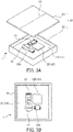
- FIGS. 3 are diagrams for explaining the muscle activity measurement device according to the first embodiment when viewed from the front, in which FIG. 3(a) is a perspective diagram for explaining a container in a state with an open lid plate, and FIG. 3(b) is a plan view for explaining the state of a front surface of a substrate housed in the container.
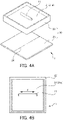
- FIGS. 4 are diagrams for explaining the muscle activity measurement device according to the first embodiment when viewed from the rear, in which FIG. 4(a) is a perspective diagram for explaining the rear side of the container in a state with an open lid plate, and FIG. 4(b) is a bottom plan view for explaining the state of a rear surface of the substrate housed in the container.
- the container 20 is formed of a container body (including a base plate) 22 which stores a substantially square substrate 21, and a substantially square lid plate 23 which covers an opening in the container body 22.
- the shape of the container 20 is not particularly limited and may be a shape other than a square, such as a rectangle or an ellipse.
- the shape of the container 20 refers to the shape of the opening in the container body 22, that is the shape of the lid plate 23.
- the first embodiment deals with a case where the shape of the opening in the container 20, that is the shape of the lid plate 23 is a substantially square shape.
- the container 20 also houses the magnetic sensor unit 11, the calculation unit 12 (AD converter 12A, recording unit 12B and control unit 12C), the wireless module unit 13 and the power supply unit 14.
- the magnetic sensor unit 11 is preferably installed on a rear surface 21a of the substrate 21 which opposes the body via the container body 22 to facilitate easy detection of magnetism in the body to be detected.
- the longitudinal direction of the magnetic sensor unit 11 to be installed is the sensing direction X.
- the calculation unit 12 (AD converter 12A, recording unit 12B and control unit 12C), the wireless module unit 13 and the power supply unit 14 are preferably mounted to a front surface 21b of the substrate 21.
- the calculation unit 12 (AD converter 12A, recording unit 12B and control unit 12C), the wireless module unit 13 and the power supply unit 14 may generate a small amount of magnetic noise such as electromagnetic waves.
- the substrate 21 which can block magnetism may be provided if the effect of magnetic noise from outside the detection direction is large.
- the container body 22 may not include a base plate, a base pate is preferably included to improve strength of the container body 22.
- the calculation unit 12 (AD converter 12A, recording unit 12B and control unit 12C), the wireless module unit 13 and the power supply unit 14 may be disposed on the same surface as the magnetic sensor unit 11 and magnetic noise from the calculation unit 12 (AD converter 12A, recording unit 12B and control unit 12C), the wireless module unit 13 and the power supply unit 14 may be prevented from reaching the magnetic sensor unit 11.
- these components are preferably disposed on the front and rear surfaces of the substrate 21 as described above.
- the positions at which the magnetic sensor unit 11, the calculation unit 12 (AD converter 12A, recording unit 12B and control unit 12C), the wireless module unit 13 and the power supply unit 14 are disposed on the substrate 21 are not particularly limited, but the center of gravity of the muscle activity measurement device 1 is preferably taken into account in consideration of stability when placing the device on the body.
- the material of the substrate 21 is preferably a material which can block environmental magnetism so that magnetic noise generated by the calculation unit 12, the wireless module unit 13 and the power supply unit 14 does not affect the muscular magnetic field.
- Examples of such a material include permalloy, ferrite, sendust or a Co-based amorphous material.
- the material of the container body 22 is not particularly limited, provided that the container body 22 blocks the magnetic field generated as a result of muscle activity in the body.
- Examples of preferable materials include polyetheretherketone (PEEK) and polyethylene terephthalate (PET) resin.
- the display 24 is disposed on the lid plate 23 of the container 20 and is a display line which extends in a direction substantially orthogonal to the sensing direction X of the magnetic sensor unit 11 housed in the container body 22.
- the form of the display 24 is not particularly limited provided that the person conducting the measurement can identify the display.
- the display 24 may be a linear symbol attached to the lid plate 23, a linear protrusion, text information, or a combination thereof.
- the display 24 may be a component provided with a seal member printed with a symbol or text information.
- the muscle activity measurement device 1 includes the display 24, the person conducting the measurement can easily identify the placement direction of the muscle activity measurement device 1 (container 20). As a result, the muscle activity measurement device 1 can more accurately measure muscle activity to be detected.
- a muscle activity measurement method is a method of disposing the muscle activity measurement device 1 on the body surface of a body 100 with the sensing direction X of the magnetic sensor unit 11 substantially orthogonal to the extending direction of muscle fibers in the body 100 to be detected.
- FIG. 5 is a schematic diagram for explaining a muscle activity measurement method according to the first embodiment.
- the display 24 is attached to the container 20 in a direction orthogonal to the sensing direction X of the magnetic sensor unit 11.
- the container 20 is disposed such that the person conducting the measurement can easily identify the placement direction using the display 24 when the muscle activity measurement device 1 (container 20) is placed on the body surface of the body 100 and the display 24 of the container 20 substantially coincides with the extension direction of the muscle fibers.
- the muscle activity measurement device 1 can detect muscular magnetic field with high sensitivity because the muscle activity measurement device 1 (container 20) is disposed such that the sensing direction X of the magnetic sensor unit 11 is substantially orthogonal to the extension direction of the muscle fibers in the body 100.
- a muscle activity measurement device 1' according to a second embodiment has the same configuration as the muscle activity measurement device 1 according to the first embodiment except for identification means for identifying the placement position of the muscle activity measurement device 1'.
- FIGS. 6 are diagrams for explaining a muscle activity measurement device according to a second embodiment of the present invention when viewed from the front, in which FIG. 6(a) is a perspective diagram for explaining a container in a state with an open lid plate, and FIG. 6(b) is a plan view for explaining the state of a front surface of a substrate housed in the container.
- FIGS. 7 are diagrams for explaining the muscle activity measurement device according to the second embodiment when viewed from the rear, in which FIG.
- FIG. 7(a) is a perspective diagram for explaining the rear side of the container in a state with an open lid plate
- FIG. 7(b) is a bottom plan view for explaining the state of a rear surface of the substrate housed in the container.
- components that are the same as those described above are denoted by the same reference symbols and descriptions thereof are omitted.
- the container 30 is formed of a container body (including a base plate) 32 which houses a substantially rectangular substrate 31, and a substantially rectangular lid plate 33 which covers an opening in the container body 32.
- the container 30 houses the magnetic sensor unit 11, the calculation unit 12 (AD converter 12A, recording unit 12B and control unit 12C), the wireless module unit 13 and the power supply unit 14.
- the magnetic sensor unit 11 is preferably placed on a rear surface 31a of the substrate 31 which opposes the body via the container body 32 to facilitate easy detection of magnetism in the body to be detected.
- the longitudinal direction of the magnetic sensor unit 11 to be placed is the sensing direction X.
- the calculation unit 12 (AD converter 12A, recording unit 12B and control unit 12C), the wireless module unit 13 and the power supply unit 14 are preferably mounted on the rear surface 31a of the substrate 31.
- the calculation unit 12 (AD converter 12A, recording unit 12B and control unit 12C), the wireless module unit 13 and the power supply unit 14 may generate a small amount of magnetic noise such as electromagnetic waves.
- the substrate 31, which can block magnetism is preferably disposed between the magnetic sensor unit 11 and the calculation unit 12, wireless module unit 13 and power supply unit 14 such that magnetic noise from outside the detection direction does not affect the muscular magnetic field.
- the positions at which the magnetic sensor unit 11, the calculation unit 12 (AD converter 12A, recording unit 12B and control unit 12C), the wireless module unit 13 and the power supply unit 14 are disposed on the substrate 31 are not particularly limited, but stability when placing the device on the body is preferably taken into account.
- the shape of the container 30 is the identification means. Because the shape of the container 30 is a rectangular shape with a longitudinal direction and a transverse direction, the person conducting the measurement can easily place the container 30 such that the longitudinal direction of the container 30 substantially coincides with the extension direction of the muscle fibers in the body to be detected. As a result, in the muscle activity measurement device 1' (container 30), the transverse direction of the container 30 and the sensing direction X of the magnetic sensor unit 11 substantially coincide with each other, and the sensing direction X of the magnetic sensor unit 11 is substantially orthogonal to the extension direction of the muscle fibers of the body 100. Because of this, muscle activity to be detected can be measured more accurately.
- a muscle activity measurement method is a method of disposing the muscle activity measurement device 1' on the body surface of the body 100 with the sensing direction X of the magnetic sensor unit 11 substantially orthogonal to the extending direction of muscle fibers in the body 100 to be detected.
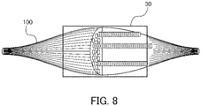
- FIG. 8 is a schematic diagram for explaining the muscle activity measurement method according to the second embodiment.
- the container 30 is formed into a rectangular shape with a longitudinal direction and a transverse direction, and the transverse direction substantially coincides with the sensing direction X of the magnetic sensor unit 11.
- the person conducting the measurement can easily identify the placement direction on the basis of the shape of the container 30 when placing the muscle activity measurement device 1' (container 30) on the body surface of the body 100.
- the device is guided such that the longitudinal direction of the container 30 substantially coincides with the extension direction of the muscle fibers in the body 100.
- the muscle activity measurement device 1' can detect the muscular magnetic field with high sensitivity because the muscle activity measurement device 1' (container 30) is disposed such that the sensing direction X of the magnetic sensor unit 11 is substantially orthogonal to the extension direction of the muscle fibers in the body 100.
- the identification means includes identification information used for placing the muscle activity measurement device 1 with the sensing direction X of the magnetic sensor unit 11 substantially orthogonal to the extension direction of the muscle fibers in the body to be detected.
- the identification means is not limited thereto, and the subject to be detected by the muscle activity measurement device according to this embodiment may be muscle cells generated by the muscular magnetic field due to muscular activity in the body.
- the subject of detection may something other than muscle fiber (skeletal muscles) such as the myocardium or smooth muscles.
- the identification means of the muscle activity measurement device may include identification information used for placing the muscle activity measurement device such that the sensing direction X of the magnetic sensor unit 11 and a direction of the muscular magnetic field of muscle fibers (skeletal muscles) or muscle activity of the myocardium or smooth muscles in the body to be detected substantially coincide.
- the muscle activity measurement device 1 was placed on the thenar eminence (see FIG. 5 ) such that the display 24 of the container 20 substantially coincided with the extension direction of muscle fibers, that is, such that the sensing direction X of the magnetic sensor unit 11 was substantially orthogonal to the extension direction of muscle fibers.
- the sensing direction X of the magnetic sensor unit 11 and the extension direction of muscle fibers were substantially orthogonal to each other.
- muscular magnetic field was measured by electrically stimulating the median nerve with the wrist. Results of the measurement are shown in FIG. 9(a) .
- the point 0 represents the timing at which electrical stimulation was applied
- the two-dot chain line represents the timing at which the muscular magnetic field was generated.
- the muscle activity measurement device 1 was placed on the thenar eminence such that the display 24 of the container 20 was orthogonal to the extension direction of muscle fibers, that is, such that the sensing direction X of the magnetic sensor unit 11 substantially coincided with the extension direction of muscle fibers. With this configuration, the sensing direction X of the magnetic sensor unit 11 and the extension direction of muscle fibers substantially coincided. Then, muscular magnetic field was measured by electrically stimulating the median nerve with the wrist. Results of the measurement are shown in FIG. 9(b) . In FIG. 9(b) , the point 0 represents the timing at which electrical stimulation was applied, and the two-dot chain line represents the timing at which the muscular magnetic field was generated.
- Example 1 in which the muscle activity measurement device 1 was placed such that the sensing direction X of the magnetic sensor unit 11 was substantially orthogonal to the extension direction of muscle fibers, the muscle measurement device 1 exhibited higher sensitivity than in Comparative Example 1 in which the muscle activity measurement device 1 was disposed such that the sensing direction X of the magnetic sensor unit 11 substantially coincided with the extension direction of muscle fibers.
- Comparative Example 1 in which the muscle activity measurement device 1 was disposed such that the sensing direction X of the magnetic sensor unit 11 substantially coincided with the extension direction of muscle fibers.
- the muscle activity measurement device 1 can more accurately measure muscle activity when disposed such that the sensing direction X of the magnetic sensor unit 11 is substantially orthogonal to the extension direction of muscle fibers.
- the muscle activity measurement devices 1 and 1' can be preferably applied to an intraoperative spinal cord and nerve function monitoring device, it goes without saying that the present invention is not limited thereto.
- the muscle activity measurement device according to the present invention may be applied to a diagnostic device used for diagnosing diseases that affect muscles, such as polymyositis, muscle dystrophy and myasthenia gravis, or diseases that affect nerves, such as peripheral neuritis, diabetic neuropathy, compressive spinal cord injury, spinal radiculopathy and amyotrophic lateral sclerosis.
- the muscle activity measurement device can also measure slight magnetic field fluctuation due to the physical contraction and expansion of blood vessels and measure the heart rate of the patient.
- the muscle activity measurement device may be applied to a measurement device configured to measure muscle activity of a patient, motor function of a patient, muscle fatigue of a patient and heart rate of a patient.
- the present invention may be applied to training purposes for athletes.
- a measurement device using a magnetic sensor such as that described above can be used.
- the muscle activity measurement device includes a wireless module unit in addition to the magnetic sensor unit, complex wires can be eliminated and user-friendliness can be improved.
- the muscle activity measurement device can instantaneously measure magnetic field fluctuations, movement amount and speed of muscle activity can also be instantaneously measured on the basis of the magnetic field fluctuations measured by the muscle activity measurement device. Therefore, the muscle activity measurement device can be applied to an intention detection device configured to instantaneously determine a response (Yes or No) to a question from the patient on the basis of the movement amount and speed of muscle activity. For example, the muscle activity measurement device can detect muscle activity of the frontalis muscle which raises and lowers the eyebrows, to thereby detect the intention of the patient.
- the container is preferably formed into a shape that can be worn by the patient.
- the identification means may be a display on the front surface of the container or may be the shape of the container in which the mounting direction is set to a predetermined direction.
- the container may be made of a flexible material formed into a strip to be wrapped around an upper arm (bicep) or femur (quadriceps).
- the muscle activity measurement device includes a wireless module unit in addition to the magnetic sensor unit in the container, complex wires can be eliminated and user-friendliness can be improved.
- the muscle activity measurement device may be mounted to a device used to support movement of the wearer by being worn on the body for the fields of rehabilitation or health support.
- the muscle activity measurement device may be mounted to a motor function improvement device for determining a support operation to supplement the function of muscle activity and drive a power unit on the basis of biomagnetic information obtained by the muscle activity measurement device.
Landscapes
- Health & Medical Sciences (AREA)
- Life Sciences & Earth Sciences (AREA)
- Medical Informatics (AREA)
- Biomedical Technology (AREA)
- Veterinary Medicine (AREA)
- Physics & Mathematics (AREA)
- Public Health (AREA)
- Biophysics (AREA)
- Pathology (AREA)
- Surgery (AREA)
- Molecular Biology (AREA)
- Heart & Thoracic Surgery (AREA)
- General Health & Medical Sciences (AREA)
- Animal Behavior & Ethology (AREA)
- Engineering & Computer Science (AREA)
- Cardiology (AREA)
- Physiology (AREA)
- Dentistry (AREA)
- Orthopedic Medicine & Surgery (AREA)
- Oral & Maxillofacial Surgery (AREA)
- Rheumatology (AREA)
- Neurology (AREA)
- Nuclear Medicine, Radiotherapy & Molecular Imaging (AREA)
- Radiology & Medical Imaging (AREA)
- Measurement And Recording Of Electrical Phenomena And Electrical Characteristics Of The Living Body (AREA)
Claims (4)
- Muskelaktivitätsmessvorrichtung (1), umfassend:eine magnetische Sensoreinheit (11), die dazu konfiguriert ist, ein von einem Körper erzeugtes Magnetfeld zu erfassen;einen Behälter (20);Identifikationsmittel, die eingerichtet ist, eine Platzierungsrichtung der Muskelaktivitätsmessvorrichtung (1) zu identifizieren, und wobei die Identifikationsmittel Identifikationsinformationen umfasst, die konfiguriert sind, um zum Platzieren der Muskelaktivitätsmessvorrichtung (1) verwendet zu werden, so dass eine Erfassungsrichtung der Magnetsensoreinheit (11) im Wesentlichen orthogonal zu einer Erstreckungsrichtung von Muskelfasern in dem zu detektierenden Körper ist, oder Identifikationsmittel Identifikationsinformationen enthält, die konfiguriert sind, um zum Platzieren der Muskelaktivitätsmessvorrichtung (1) verwendet zu werden, so dass eine Erfassungsrichtung der magnetischen Sensoreinheit (11) im Wesentlichen mit einer Richtung eines muskulären Magnetfelds zusammenfällt, das aufgrund einer Muskelaktivität in dem zu erfassenden Körper erzeugt wird,eine Berechnungseinheit (12), die dazu konfiguriert ist, biomagnetische Informationen auf der Grundlage eines von der Magnetsensoreinheit (11) erfassten Signals zu erzeugen;ein Funkmodul (13), das dazu konfiguriert ist, die von der Berechnungseinheit (12) erzeugten biomagnetischen Informationen drahtlos an eine externe Vorrichtung zu übertragen; undeine Energieversorgungseinheit (14), die dazu konfiguriert ist, der Magnetsensoreinheit (11), der Berechnungseinheit (12) und dem Funkmodul (13) elektrische Energie zuzuführen,wobei die Identifikationsinformationen eine Anzeige (24) der Platzierungsrichtung der Muskelaktivitätsmessvorrichtung (1) auf der Vorderfläche des Behälters (20) oder eine Form des Behälters (20) sind,der Behälter (20) einen Behälterkörper (22), der ein Substrat (21) mit einer Vorderfläche und einer Rückfläche umfasst, wobei das Substrat (21) aus einem Material hergestellt ist, das so konfiguriert ist, dass es Umgebungsmagnetismus blockiert, und eine Öffnung auf einer Vorderflächenseite des Substrats (21) aufweist, und eine Deckelplatte (23) aufweist, die die Öffnung des Behälterkörpers (22) abdeckt und eine Innenfläche, die der Vorderfläche des Substrats (21) zugewandt ist, und eine Außenfläche aufweist,die Magnetsensoreinheit (11) auf der Rückseite des Substrats (21) des Behälters (20) vorgesehen ist,das Identifikationsmittel auf der Außenfläche der Deckelplatte (23) des Behälters (20) vorgesehen ist, unddie Berechnungseinheit (12) und das Funkmodul (13) an der Vorderfläche des Substrats (21) montiert sind.
- Muskelaktivitätsmessvorrichtung nach Anspruch 1, wobei der Behälter (20) eine rechteckige Form oder eine elliptische Form hat.
- Muskelaktivitätsmessvorrichtung nach Anspruch 2, wobei eine Querrichtung des Behälters (20) im Wesentlichen mit einer Erfassungsrichtung der Magnetsensoreinheit (11) zusammenfällt.
- Muskelaktivitäts-Messverfahren, umfassend das Anordnen der Muskelaktivitätsmessvorrichtung (1) nach Anspruch 1 auf einer Körperoberfläche des Körpers mit einer Erfassungsrichtung der Magnetsensoreinheit (11), die im Wesentlichen orthogonal zu einer Erstreckungsrichtung von Muskelfasern in dem Körper ist oder mit dieser im Wesentlichen zusammenfällt.
Applications Claiming Priority (2)
| Application Number | Priority Date | Filing Date | Title |
|---|---|---|---|
| JP2016114482 | 2016-06-08 | ||
| PCT/JP2017/020955 WO2017213127A1 (ja) | 2016-06-08 | 2017-06-06 | 筋活動測定装置及び筋活動測定方法 |
Publications (3)
| Publication Number | Publication Date |
|---|---|
| EP3469985A1 EP3469985A1 (de) | 2019-04-17 |
| EP3469985A4 EP3469985A4 (de) | 2019-11-06 |
| EP3469985B1 true EP3469985B1 (de) | 2022-08-17 |
Family
ID=60577843
Family Applications (1)
| Application Number | Title | Priority Date | Filing Date |
|---|---|---|---|
| EP17810302.4A Active EP3469985B1 (de) | 2016-06-08 | 2017-06-06 | Muskelaktivitätsmessvorrichtung und muskelaktivitätsmessverfahren |
Country Status (5)
| Country | Link |
|---|---|
| US (1) | US11412945B2 (de) |
| EP (1) | EP3469985B1 (de) |
| JP (1) | JP6857367B2 (de) |
| CN (1) | CN109310358B (de) |
| WO (1) | WO2017213127A1 (de) |
Families Citing this family (3)
| Publication number | Priority date | Publication date | Assignee | Title |
|---|---|---|---|---|
| JP2020092982A (ja) * | 2018-12-14 | 2020-06-18 | 株式会社リコー | 生体磁場計測装置、生体磁場計測方法 |
| JP2020069350A (ja) * | 2018-11-02 | 2020-05-07 | 株式会社リコー | 生体磁場検出装置 |
| US12564346B2 (en) * | 2022-11-15 | 2026-03-03 | Twinleaf Llc | Unshielded pulsed pump magnetometers for biomagnetic measurements |
Family Cites Families (11)
| Publication number | Priority date | Publication date | Assignee | Title |
|---|---|---|---|---|
| JP3197414B2 (ja) | 1993-12-22 | 2001-08-13 | 科学技術振興事業団 | 磁気インピーダンス効果素子 |
| CN100553555C (zh) | 2004-01-15 | 2009-10-28 | 皇家飞利浦电子股份有限公司 | 自适应生理监视系统及其使用方法 |
| JP2008178558A (ja) * | 2007-01-24 | 2008-08-07 | Hitachi High-Technologies Corp | 生体磁場計測装置 |
| US7922773B1 (en) * | 2008-05-16 | 2011-04-12 | Rehabilitation Institute Of Chicago | Method and apparatus for prosthetic limb rotation control |
| JP2010051682A (ja) * | 2008-08-29 | 2010-03-11 | Tokyo Metropolitan Univ | 筋活動測定装置、筋活動測定システム、意思検出システム、筋疲労測定システム、運動機能測定システム、心拍測定システムおよび自立行動支援システム |
| JP5433474B2 (ja) | 2010-03-24 | 2014-03-05 | パナソニック株式会社 | 体脂肪測定装置 |
| CN103068302B (zh) * | 2010-05-13 | 2016-09-07 | 合理医疗创新有限公司 | 使用分布式电磁(em)组织监测的方法及系统 |
| JP5641203B2 (ja) | 2010-06-10 | 2014-12-17 | 国立大学法人静岡大学 | R波検出装置及びr波計測システム |
| US20150366504A1 (en) * | 2014-06-20 | 2015-12-24 | Medibotics Llc | Electromyographic Clothing |
| MX2015015288A (es) * | 2013-07-24 | 2016-03-11 | California Inst Of Techn | Diseño y fabricacion de sensores electroquimicos implantables totalmente integrados. |
| JP5913485B2 (ja) * | 2014-08-29 | 2016-04-27 | 日本電信電話株式会社 | 生体信号モニタシステム |
-
2017
- 2017-06-06 WO PCT/JP2017/020955 patent/WO2017213127A1/ja not_active Ceased
- 2017-06-06 CN CN201780034727.3A patent/CN109310358B/zh active Active
- 2017-06-06 US US16/307,192 patent/US11412945B2/en active Active
- 2017-06-06 EP EP17810302.4A patent/EP3469985B1/de active Active
- 2017-06-06 JP JP2018522502A patent/JP6857367B2/ja active Active
Also Published As
| Publication number | Publication date |
|---|---|
| EP3469985A4 (de) | 2019-11-06 |
| CN109310358A (zh) | 2019-02-05 |
| US11412945B2 (en) | 2022-08-16 |
| EP3469985A1 (de) | 2019-04-17 |
| JP6857367B2 (ja) | 2021-04-14 |
| JPWO2017213127A1 (ja) | 2019-07-11 |
| CN109310358B (zh) | 2022-08-09 |
| WO2017213127A1 (ja) | 2017-12-14 |
| US20190125205A1 (en) | 2019-05-02 |
Similar Documents
| Publication | Publication Date | Title |
|---|---|---|
| EP3383262B1 (de) | Nervenstimulationsvorrichtung und messsystem für biomagnetisches feld | |
| CN1933777B (zh) | 生物体信息计测用系统、呼吸信息分析装置、分析装置控制法 | |
| TWI308066B (en) | Electrodynamic sensors and applications thereof | |
| US9113808B2 (en) | Systems, methods, and sensors for measuring tissue | |
| EP3138489B1 (de) | Kit zur bestimmung einer analytkonzentration | |
| WO2006124481A3 (en) | Implantable medical device with mri and gradient field induced capture detection methods | |
| US11412945B2 (en) | Muscle activity measurement device and muscle activity measurement method | |
| US9026189B2 (en) | Electrode sensor assembly for electroretinography and pattern electroretinography | |
| EP2886054A1 (de) | Niedrigprofil-Positionsblock für magnetbasiertes intrakorporales Sondeverfolgungssystem | |
| KR102568960B1 (ko) | 두개내압의 비침습적 관리 및 모니터링을 위한 방법 및 시스템, 그리고 두개골 용적 변화의 측정을 위한 장치 | |
| US11950913B2 (en) | Electrocardiogram sensor | |
| US20140221772A1 (en) | Body surface sensors | |
| US20130317334A1 (en) | Position sensing using electric dipole fields | |
| US10772523B2 (en) | Non-invasive system and method of spatial localization of specific electrocardiac elements | |
| CN108095715A (zh) | 一种植入式无线无源颅内压力监测系统 | |
| US11344239B2 (en) | Non-invasive system and method of spatial localization of specific electrocardiac elements | |
| JP2017113367A (ja) | 運動機能測定用センサ及び運動機能測定システム | |
| US20220257212A1 (en) | Non-invasive system and method of spatial localization of specific electrocardiac elements | |
| US12527488B2 (en) | Brain function measurement device and brain function measurement method | |
| JP2007268034A (ja) | 生体信号計測方法及び装置 | |
| Bassen | Low frequency magnetic emissions and resulting induced voltages in a pacemaker by iPod portable music players | |
| CN208404560U (zh) | 一种植入式无线无源颅内压力监测系统 | |
| EP3463067A1 (de) | Elektrokardiogramm-patch | |
| CN121154138A (zh) | 基于磁场强度的呼吸检测装置及方法 | |
| US20140073483A1 (en) | Muscle activity training facility for upper body of user |
Legal Events
| Date | Code | Title | Description |
|---|---|---|---|
| STAA | Information on the status of an ep patent application or granted ep patent |
Free format text: STATUS: THE INTERNATIONAL PUBLICATION HAS BEEN MADE |
|
| PUAI | Public reference made under article 153(3) epc to a published international application that has entered the european phase |
Free format text: ORIGINAL CODE: 0009012 |
|
| STAA | Information on the status of an ep patent application or granted ep patent |
Free format text: STATUS: REQUEST FOR EXAMINATION WAS MADE |
|
| 17P | Request for examination filed |
Effective date: 20181231 |
|
| AK | Designated contracting states |
Kind code of ref document: A1 Designated state(s): AL AT BE BG CH CY CZ DE DK EE ES FI FR GB GR HR HU IE IS IT LI LT LU LV MC MK MT NL NO PL PT RO RS SE SI SK SM TR |
|
| AX | Request for extension of the european patent |
Extension state: BA ME |
|
| DAV | Request for validation of the european patent (deleted) | ||
| DAX | Request for extension of the european patent (deleted) | ||
| A4 | Supplementary search report drawn up and despatched |
Effective date: 20191004 |
|
| RIC1 | Information provided on ipc code assigned before grant |
Ipc: A61B 5/04 20060101AFI20190927BHEP Ipc: A61B 5/06 20060101ALN20190927BHEP Ipc: A61B 5/00 20060101ALI20190927BHEP |
|
| STAA | Information on the status of an ep patent application or granted ep patent |
Free format text: STATUS: EXAMINATION IS IN PROGRESS |
|
| 17Q | First examination report despatched |
Effective date: 20210317 |
|
| REG | Reference to a national code |
Ref country code: DE Ref legal event code: R079 Ref document number: 602017060798 Country of ref document: DE Free format text: PREVIOUS MAIN CLASS: A61B0005050000 Ipc: A61B0005242000 |
|
| GRAP | Despatch of communication of intention to grant a patent |
Free format text: ORIGINAL CODE: EPIDOSNIGR1 |
|
| STAA | Information on the status of an ep patent application or granted ep patent |
Free format text: STATUS: GRANT OF PATENT IS INTENDED |
|
| RIC1 | Information provided on ipc code assigned before grant |
Ipc: A61B 5/06 20060101ALN20220224BHEP Ipc: A61B 5/00 20060101ALI20220224BHEP Ipc: A61B 5/242 20210101AFI20220224BHEP |
|
| INTG | Intention to grant announced |
Effective date: 20220318 |
|
| GRAS | Grant fee paid |
Free format text: ORIGINAL CODE: EPIDOSNIGR3 |
|
| GRAA | (expected) grant |
Free format text: ORIGINAL CODE: 0009210 |
|
| STAA | Information on the status of an ep patent application or granted ep patent |
Free format text: STATUS: THE PATENT HAS BEEN GRANTED |
|
| AK | Designated contracting states |
Kind code of ref document: B1 Designated state(s): AL AT BE BG CH CY CZ DE DK EE ES FI FR GB GR HR HU IE IS IT LI LT LU LV MC MK MT NL NO PL PT RO RS SE SI SK SM TR |
|
| REG | Reference to a national code |
Ref country code: CH Ref legal event code: EP |
|
| REG | Reference to a national code |
Ref country code: DE Ref legal event code: R096 Ref document number: 602017060798 Country of ref document: DE |
|
| REG | Reference to a national code |
Ref country code: IE Ref legal event code: FG4D |
|
| REG | Reference to a national code |
Ref country code: AT Ref legal event code: REF Ref document number: 1511638 Country of ref document: AT Kind code of ref document: T Effective date: 20220915 |
|
| REG | Reference to a national code |
Ref country code: NL Ref legal event code: MP Effective date: 20220817 |
|
| REG | Reference to a national code |
Ref country code: LT Ref legal event code: MG9D |
|
| PG25 | Lapsed in a contracting state [announced via postgrant information from national office to epo] |
Ref country code: SE Free format text: LAPSE BECAUSE OF FAILURE TO SUBMIT A TRANSLATION OF THE DESCRIPTION OR TO PAY THE FEE WITHIN THE PRESCRIBED TIME-LIMIT Effective date: 20220817 Ref country code: RS Free format text: LAPSE BECAUSE OF FAILURE TO SUBMIT A TRANSLATION OF THE DESCRIPTION OR TO PAY THE FEE WITHIN THE PRESCRIBED TIME-LIMIT Effective date: 20220817 Ref country code: PT Free format text: LAPSE BECAUSE OF FAILURE TO SUBMIT A TRANSLATION OF THE DESCRIPTION OR TO PAY THE FEE WITHIN THE PRESCRIBED TIME-LIMIT Effective date: 20221219 Ref country code: NO Free format text: LAPSE BECAUSE OF FAILURE TO SUBMIT A TRANSLATION OF THE DESCRIPTION OR TO PAY THE FEE WITHIN THE PRESCRIBED TIME-LIMIT Effective date: 20221117 Ref country code: NL Free format text: LAPSE BECAUSE OF FAILURE TO SUBMIT A TRANSLATION OF THE DESCRIPTION OR TO PAY THE FEE WITHIN THE PRESCRIBED TIME-LIMIT Effective date: 20220817 Ref country code: LV Free format text: LAPSE BECAUSE OF FAILURE TO SUBMIT A TRANSLATION OF THE DESCRIPTION OR TO PAY THE FEE WITHIN THE PRESCRIBED TIME-LIMIT Effective date: 20220817 Ref country code: LT Free format text: LAPSE BECAUSE OF FAILURE TO SUBMIT A TRANSLATION OF THE DESCRIPTION OR TO PAY THE FEE WITHIN THE PRESCRIBED TIME-LIMIT Effective date: 20220817 Ref country code: FI Free format text: LAPSE BECAUSE OF FAILURE TO SUBMIT A TRANSLATION OF THE DESCRIPTION OR TO PAY THE FEE WITHIN THE PRESCRIBED TIME-LIMIT Effective date: 20220817 |
|
| REG | Reference to a national code |
Ref country code: AT Ref legal event code: MK05 Ref document number: 1511638 Country of ref document: AT Kind code of ref document: T Effective date: 20220817 |
|
| PG25 | Lapsed in a contracting state [announced via postgrant information from national office to epo] |
Ref country code: PL Free format text: LAPSE BECAUSE OF FAILURE TO SUBMIT A TRANSLATION OF THE DESCRIPTION OR TO PAY THE FEE WITHIN THE PRESCRIBED TIME-LIMIT Effective date: 20220817 Ref country code: IS Free format text: LAPSE BECAUSE OF FAILURE TO SUBMIT A TRANSLATION OF THE DESCRIPTION OR TO PAY THE FEE WITHIN THE PRESCRIBED TIME-LIMIT Effective date: 20221217 Ref country code: HR Free format text: LAPSE BECAUSE OF FAILURE TO SUBMIT A TRANSLATION OF THE DESCRIPTION OR TO PAY THE FEE WITHIN THE PRESCRIBED TIME-LIMIT Effective date: 20220817 Ref country code: GR Free format text: LAPSE BECAUSE OF FAILURE TO SUBMIT A TRANSLATION OF THE DESCRIPTION OR TO PAY THE FEE WITHIN THE PRESCRIBED TIME-LIMIT Effective date: 20221118 |
|
| PG25 | Lapsed in a contracting state [announced via postgrant information from national office to epo] |
Ref country code: SM Free format text: LAPSE BECAUSE OF FAILURE TO SUBMIT A TRANSLATION OF THE DESCRIPTION OR TO PAY THE FEE WITHIN THE PRESCRIBED TIME-LIMIT Effective date: 20220817 Ref country code: RO Free format text: LAPSE BECAUSE OF FAILURE TO SUBMIT A TRANSLATION OF THE DESCRIPTION OR TO PAY THE FEE WITHIN THE PRESCRIBED TIME-LIMIT Effective date: 20220817 Ref country code: ES Free format text: LAPSE BECAUSE OF FAILURE TO SUBMIT A TRANSLATION OF THE DESCRIPTION OR TO PAY THE FEE WITHIN THE PRESCRIBED TIME-LIMIT Effective date: 20220817 Ref country code: DK Free format text: LAPSE BECAUSE OF FAILURE TO SUBMIT A TRANSLATION OF THE DESCRIPTION OR TO PAY THE FEE WITHIN THE PRESCRIBED TIME-LIMIT Effective date: 20220817 Ref country code: CZ Free format text: LAPSE BECAUSE OF FAILURE TO SUBMIT A TRANSLATION OF THE DESCRIPTION OR TO PAY THE FEE WITHIN THE PRESCRIBED TIME-LIMIT Effective date: 20220817 Ref country code: AT Free format text: LAPSE BECAUSE OF FAILURE TO SUBMIT A TRANSLATION OF THE DESCRIPTION OR TO PAY THE FEE WITHIN THE PRESCRIBED TIME-LIMIT Effective date: 20220817 |
|
| REG | Reference to a national code |
Ref country code: DE Ref legal event code: R097 Ref document number: 602017060798 Country of ref document: DE |
|
| PG25 | Lapsed in a contracting state [announced via postgrant information from national office to epo] |
Ref country code: SK Free format text: LAPSE BECAUSE OF FAILURE TO SUBMIT A TRANSLATION OF THE DESCRIPTION OR TO PAY THE FEE WITHIN THE PRESCRIBED TIME-LIMIT Effective date: 20220817 Ref country code: EE Free format text: LAPSE BECAUSE OF FAILURE TO SUBMIT A TRANSLATION OF THE DESCRIPTION OR TO PAY THE FEE WITHIN THE PRESCRIBED TIME-LIMIT Effective date: 20220817 |
|
| PLBE | No opposition filed within time limit |
Free format text: ORIGINAL CODE: 0009261 |
|
| STAA | Information on the status of an ep patent application or granted ep patent |
Free format text: STATUS: NO OPPOSITION FILED WITHIN TIME LIMIT |
|
| PG25 | Lapsed in a contracting state [announced via postgrant information from national office to epo] |
Ref country code: AL Free format text: LAPSE BECAUSE OF FAILURE TO SUBMIT A TRANSLATION OF THE DESCRIPTION OR TO PAY THE FEE WITHIN THE PRESCRIBED TIME-LIMIT Effective date: 20220817 |
|
| 26N | No opposition filed |
Effective date: 20230519 |
|
| PG25 | Lapsed in a contracting state [announced via postgrant information from national office to epo] |
Ref country code: SI Free format text: LAPSE BECAUSE OF FAILURE TO SUBMIT A TRANSLATION OF THE DESCRIPTION OR TO PAY THE FEE WITHIN THE PRESCRIBED TIME-LIMIT Effective date: 20220817 |
|
| REG | Reference to a national code |
Ref country code: DE Ref legal event code: R081 Ref document number: 602017060798 Country of ref document: DE Owner name: TDK CORPORATION, JP Free format text: FORMER OWNERS: NATIONAL UNIVERSITY CORPORATION TOKYO MEDICAL AND DENTAL UNIVERSITY, TOKYO, JP; TDK CORPORATION, TOKYO, JP |
|
| REG | Reference to a national code |
Ref country code: GB Ref legal event code: 732E Free format text: REGISTERED BETWEEN 20230901 AND 20230906 |
|
| PG25 | Lapsed in a contracting state [announced via postgrant information from national office to epo] |
Ref country code: MC Free format text: LAPSE BECAUSE OF FAILURE TO SUBMIT A TRANSLATION OF THE DESCRIPTION OR TO PAY THE FEE WITHIN THE PRESCRIBED TIME-LIMIT Effective date: 20220817 |
|
| PG25 | Lapsed in a contracting state [announced via postgrant information from national office to epo] |
Ref country code: MC Free format text: LAPSE BECAUSE OF FAILURE TO SUBMIT A TRANSLATION OF THE DESCRIPTION OR TO PAY THE FEE WITHIN THE PRESCRIBED TIME-LIMIT Effective date: 20220817 |
|
| REG | Reference to a national code |
Ref country code: CH Ref legal event code: PL |
|
| REG | Reference to a national code |
Ref country code: BE Ref legal event code: MM Effective date: 20230630 |
|
| PG25 | Lapsed in a contracting state [announced via postgrant information from national office to epo] |
Ref country code: LU Free format text: LAPSE BECAUSE OF NON-PAYMENT OF DUE FEES Effective date: 20230606 |
|
| REG | Reference to a national code |
Ref country code: IE Ref legal event code: MM4A |
|
| PG25 | Lapsed in a contracting state [announced via postgrant information from national office to epo] |
Ref country code: LU Free format text: LAPSE BECAUSE OF NON-PAYMENT OF DUE FEES Effective date: 20230606 |
|
| PG25 | Lapsed in a contracting state [announced via postgrant information from national office to epo] |
Ref country code: IE Free format text: LAPSE BECAUSE OF NON-PAYMENT OF DUE FEES Effective date: 20230606 |
|
| PG25 | Lapsed in a contracting state [announced via postgrant information from national office to epo] |
Ref country code: IE Free format text: LAPSE BECAUSE OF NON-PAYMENT OF DUE FEES Effective date: 20230606 Ref country code: CH Free format text: LAPSE BECAUSE OF NON-PAYMENT OF DUE FEES Effective date: 20230630 |
|
| PG25 | Lapsed in a contracting state [announced via postgrant information from national office to epo] |
Ref country code: IT Free format text: LAPSE BECAUSE OF FAILURE TO SUBMIT A TRANSLATION OF THE DESCRIPTION OR TO PAY THE FEE WITHIN THE PRESCRIBED TIME-LIMIT Effective date: 20220817 Ref country code: FR Free format text: LAPSE BECAUSE OF NON-PAYMENT OF DUE FEES Effective date: 20230630 Ref country code: BE Free format text: LAPSE BECAUSE OF NON-PAYMENT OF DUE FEES Effective date: 20230630 |
|
| PG25 | Lapsed in a contracting state [announced via postgrant information from national office to epo] |
Ref country code: BG Free format text: LAPSE BECAUSE OF FAILURE TO SUBMIT A TRANSLATION OF THE DESCRIPTION OR TO PAY THE FEE WITHIN THE PRESCRIBED TIME-LIMIT Effective date: 20220817 |
|
| PG25 | Lapsed in a contracting state [announced via postgrant information from national office to epo] |
Ref country code: BG Free format text: LAPSE BECAUSE OF FAILURE TO SUBMIT A TRANSLATION OF THE DESCRIPTION OR TO PAY THE FEE WITHIN THE PRESCRIBED TIME-LIMIT Effective date: 20220817 |
|
| PGFP | Annual fee paid to national office [announced via postgrant information from national office to epo] |
Ref country code: DE Payment date: 20250618 Year of fee payment: 9 |
|
| PGFP | Annual fee paid to national office [announced via postgrant information from national office to epo] |
Ref country code: GB Payment date: 20250618 Year of fee payment: 9 |
|
| PG25 | Lapsed in a contracting state [announced via postgrant information from national office to epo] |
Ref country code: CY Free format text: LAPSE BECAUSE OF FAILURE TO SUBMIT A TRANSLATION OF THE DESCRIPTION OR TO PAY THE FEE WITHIN THE PRESCRIBED TIME-LIMIT; INVALID AB INITIO Effective date: 20170606 |
|
| PG25 | Lapsed in a contracting state [announced via postgrant information from national office to epo] |
Ref country code: HU Free format text: LAPSE BECAUSE OF FAILURE TO SUBMIT A TRANSLATION OF THE DESCRIPTION OR TO PAY THE FEE WITHIN THE PRESCRIBED TIME-LIMIT; INVALID AB INITIO Effective date: 20170606 |
|
| PG25 | Lapsed in a contracting state [announced via postgrant information from national office to epo] |
Ref country code: TR Free format text: LAPSE BECAUSE OF FAILURE TO SUBMIT A TRANSLATION OF THE DESCRIPTION OR TO PAY THE FEE WITHIN THE PRESCRIBED TIME-LIMIT Effective date: 20220817 |