EP3469937A2 - Atomizer and electronic cigarette having same - Google Patents
Atomizer and electronic cigarette having same Download PDFInfo
- Publication number
- EP3469937A2 EP3469937A2 EP19155989.7A EP19155989A EP3469937A2 EP 3469937 A2 EP3469937 A2 EP 3469937A2 EP 19155989 A EP19155989 A EP 19155989A EP 3469937 A2 EP3469937 A2 EP 3469937A2
- Authority
- EP
- European Patent Office
- Prior art keywords
- heating
- liquid
- hole
- atomizer
- liquid storage
- Prior art date
- Legal status (The legal status is an assumption and is not a legal conclusion. Google has not performed a legal analysis and makes no representation as to the accuracy of the status listed.)
- Pending
Links
Images




Classifications
-
- A—HUMAN NECESSITIES
- A24—TOBACCO; CIGARS; CIGARETTES; SIMULATED SMOKING DEVICES; SMOKERS' REQUISITES
- A24F—SMOKERS' REQUISITES; MATCH BOXES; SIMULATED SMOKING DEVICES
- A24F40/00—Electrically operated smoking devices; Component parts thereof; Manufacture thereof; Maintenance or testing thereof; Charging means specially adapted therefor
- A24F40/40—Constructional details, e.g. connection of cartridges and battery parts
- A24F40/46—Shape or structure of electric heating means
-
- A—HUMAN NECESSITIES
- A24—TOBACCO; CIGARS; CIGARETTES; SIMULATED SMOKING DEVICES; SMOKERS' REQUISITES
- A24F—SMOKERS' REQUISITES; MATCH BOXES; SIMULATED SMOKING DEVICES
- A24F40/00—Electrically operated smoking devices; Component parts thereof; Manufacture thereof; Maintenance or testing thereof; Charging means specially adapted therefor
- A24F40/40—Constructional details, e.g. connection of cartridges and battery parts
- A24F40/48—Fluid transfer means, e.g. pumps
- A24F40/485—Valves; Apertures
-
- A—HUMAN NECESSITIES
- A24—TOBACCO; CIGARS; CIGARETTES; SIMULATED SMOKING DEVICES; SMOKERS' REQUISITES
- A24F—SMOKERS' REQUISITES; MATCH BOXES; SIMULATED SMOKING DEVICES
- A24F40/00—Electrically operated smoking devices; Component parts thereof; Manufacture thereof; Maintenance or testing thereof; Charging means specially adapted therefor
- A24F40/10—Devices using liquid inhalable precursors
Definitions
- the present disclosure relates to the field of electronic cigarettes, and particularly to an atomizer and an electronic cigarette having same.
- the electronic cigarettes containing tobacco liquid generates an aerosol mainly by an atomizer heating the tobacco liquid.
- They have advantages of good portability, no open flame and environmental friendly, becoming one of mature alternatives to smoking, therefore enjoying a popularity boom by smokers.
- the electronic cigarettes containing tobacco liquid have problems of different levels of tobacco leakage.
- the tobacco liquid leak to outside of the atomizer, it would influence a heating effect.
- a method known to inventors the problem of tobacco leakage is mainly realized by changing structures of air passages or adjusting tobacco storage medium, however, by this way, it only improves a problem of tobacco leaking to outside, failing to avoid leakage of the tobacco liquid to inside of the atomizer.
- the present disclosure relates to an atomizer and an electronic cigarette having the same, which are capable of preventing tobacco liquid therein from leaking into the atomizer.
- the atomizer includes: a liquid storage chamber configured for storing tobacco liquid; the liquid storage chamber includes a liquid conducting hole; a heating component including at least one heating element and a case; the at least one heating element being received in the case; and between the heating element and the case or between the adjacent heating elements including a liquid storage sump; the heating component being connected with the liquid storage chamber; and the heating element being disposed under the liquid storage chamber and corresponding with the liquid conductive hole; the tobacco liquid in the liquid storage chamber flowing towards the heating element, through the liquid conductive hole, the heating element heating the tobacco liquid for atomization; the liquid storage sump being configured for storing some of tobacco liquid leaking from the heating element, further the heating element atomizes the tobacco liquid in the liquid storage sump.
- a heating box being made by heat conductive materials, the heating box including a heating compartment formed therein, an upper opening of the heating box being corresponding with the liquid conductive hole; a heating area, formed on the heating box; and an absorption element, filled in the heating compartment; the absorption element contacting the liquid conductive hole;
- the heating box is made by ceramic materials; the heating area is a resistive circuit printed on an outside or inside surface of the heating box.
- a first through hole is bored on a lateral of the heating element; the first through extends through the heating element and is configured for guiding an aerosol generated by atomizing the tobacco liquid to outside of the heating element.
- the case has a second through hole bored thereon, the second through hole is configured for guiding exterior air into the case;
- the heating element is received in the case, the first through hole and the second through hole are communicated with each other to form an air passage;
- a total number of the first through holes is at least one
- a total number of the second through holes is at least one; and a position of each second through hole bored is higher than a bottom of the liquid storage sump;
- the atomizer further includes: an air pipe, passing through the liquid storage chamber, and one end of the air pipe is communicated with inside the case;
- the liquid storage chamber further includes: a shell; a top cover, connected with one end of the shell, a first through hole is bored on the top cover; a fixing base, connected with another end of the shell; the fixing base has a second through hole communicated with the case; one end of the air pipe is fixed inside the second through hole; an opposite end of the air pipe is fixed inside the first through hole.
- the liquid conducting hole is bored on the base;
- the fixing base further has a groove formed thereon; the groove is communicated with the liquid conducting hole and the second through hole, configured for installing the heating component.
- the atomizer further includes: a base, the base is connected with the liquid storage chamber to form a case; the heating component is disposed in the case.
- the present disclosure further provides an electronic cigarette having the atomizer as described supra and a power supply module; the power supply module is coupled with the atomizer and configured for supplying power to the atomizer.
- the present disclosure relates to an atomizer and an electronic cigarette having same;
- the atomizer includes a liquid storage chamber and a heating component.
- the heating component includes a heating element and a case, the heating element is received in the case and a liquid storage sump is formed there-between.
- the heating component is connected with the liquid storage chamber and the heating element is disposed above the liquid conductive hole so that the tobacco liquid stored in the liquid storage chamber will flow by gravity, towards the heating element for atomization.
- the leaking tobacco liquid would flow towards the heating component, stored in the liquid storage sump of the heating component, thus the leaking tobacco is only capable of being stored in the heating component and can't leak to the inside air pipe of the atomizer, which effectively avoids the tobacco liquid to be drawn by the user, enhancing the user experience.
- 1 represents the electronic cigarette
- 10 represents the atomizer
- 11 represents the liquid storage chamber
- 111 represents the top cover
- 1111 represents the first through hole
- 112 represents the shell
- 113 represents the fixing base
- 1131 represents the basal portion
- 11311 is the liquid conductive hole
- 11312 is the second air hole
- 11313 is the groove
- 1132 is the extending portion
- 114 is the sealing glue
- 12 is the heating component
- 121 is the case
- 1211 is the second through hole
- 1212 is the slot
- 122 is the heating element
- 1221 is the heating box
- 12211 is the heating compartment
- 1222 is an absorption element
- 1223 is the heating area
- 1224 is the first through hole
- 123 is the liquid storage sump
- 13 is the air pipe
- 14 is the base
- 141 is the threaded connector
- 15 is the case
- 20 is the power supply.
- FIG. 1 is an aspect view of an electronic cigarette in accordance with one embodiment of the present disclosure.
- the electronic cigarette includes: an atomizer 10 and a power supply 20, the power supply 20 is couple with the atomizer 10 to supply power to the atomizer 10, allowing the atomizer 10 to heat the tobacco liquid for atomization, to generate an aerosol.
- the power supply 20 is detachably connected with the atomizer 10 via a threaded connector 141.
- the power supply 20 and the atomizer 10 may be coupled via other methods, such as snap fit and rivet joint etc.
- the atomizer 10 includes: a liquid storage chamber 11, a heating component 12, an air pipe 13 and a base 14.
- the liquid storage chamber 11 is connected with the base 14 and the liquid storage chamber 11 is located above the base 14. Between the liquid storage chamber 11 and the base 14 has a case 15 formed there-between.
- the heating component 12 is connected with the liquid storage chamber 11 and the heating component 12 is disposed in the case 15; that means the heating component 12 is disposed between the liquid storage chamber 11 and the base 14.
- the air pipe 13 is passing through the liquid storage chamber 11 and one end of the air pipe 13 is communicated with the heating component 12, enabling an aerosol generated by that the heating component 12 heats the tobacco liquid, to pass through the air pipe 13 so as to supply to the user.
- the liquid storage chamber 11 includes a shell 112, a top cover 11 and a fixing base 113; the top cover 11, the shell 112 and the fixing base 113 are successively connected from top to bottom.
- the top cover 111 has a first through hole 1111, the first through hole 1111 is a round-shaped through hole, passing through the top cover 111, located at a middle of the top cover 111, that is, the central axial of the first through hole 1111 is coaxial with the central axial of the top cover 111.
- the fixing base 113 includes a basal portion 1131 and an extending portion 1132 extending from the basal portion 1131.
- the basal portion 1131 is a cylinder; the basal portion 1131 of the fixing base 113 is bored with a liquid conducting hole 11311, a second air hole 11312 and a groove 11313. Specifically, the groove 11313 is positioned at a central of the bottom of the basal portion 1131.
- the groove 11313 is a rectangular-shaped groove, sinking upwards rather than passing through the basal portion 1131 and configured for installing the heating component 12.
- the basal portion 1131 has the liquid conducting hole 11311 and the second air hole 11312 bored thereon, corresponding with the groove 11313.
- the liquid conducting hole 11311 and the second air hole 11312 opened on the basal portion 1131 are both communicated with the groove 11313.
- the liquid conducting hole 11311 and the second air hole 11312 don't extend within the groove 11313.
- the second air hole 11312 is a round-shaped air hole, located at a central of the basal portion 1131, corresponding with the first air hole 1111, that means, the central axes of the first air hole 1111 and the second air hole 11312 are coaxial with each other.
- the liquid conducting hole 11311 is a rectangular-shaped through hole.
- the number of the liquid conducting hole 11311 is at least one, in the embodiments of the present disclosure, the number of the liquid conducting holes 11311 is four, each side of the second through hole 11312 has two of the four liquid conducting holes 11311 disposed symmetrically.
- the extending part 1132 is a cylinder-structure
- the fixing base 113 is rivet jointed with the base 14 via the extending part 1132, with the base 14 to form the case 15.
- the shell 112 is a cylindrical structure, one end of the shell 112 is rivet jointed with the top cover 111 via a sealing glue 114; an opposite end of the shell 112 is rivet jointed with the basal portion 1131 via the sealing glue 114; a liquid storage chamber 11 formed by sealing connection of the shell 112, the top cover 111 and the fixing base 113, is configured for storing tobacco liquid, so the shell 112 is generally made by transparent materials, such as, glasses, which is convenient for users to see-through.
- the heating component 12 is a core of the atomizer 10 heating the tobacco liquid, which includes: a case 121 and at least one heating element 122.
- the at least one heating element 122 is received in the case 121.
- a liquid storage sump 123 is formed between the heating element 122 and the case 121 or between adjacent heating elements 122.
- the liquid storage sump 123 is configured for storing some of tobacco liquid leaking from the heating element 122, causing the heating element 122 to heat the leaking tobacco liquid stored in the liquid storage sump 123 to generate an aerosol.
- the case 121 is rectangular-shaped, the size thereof is the same as the size of the groove 11313, enabling the heating component 12 to be installed in the groove 11313, the case 121 is rivet joint with the groove 11313, moreover, the inside of the case 121 is communicated with the second air hole 11312.
- Two opposite side walls of the case 121 have the second through holes 1211 opposite with each other, the side wall is bounded by the intersection of a width and a height, P1 and P2 shown in FIG. 6 .
- the second through holes 1211 are configured for allowing exterior air to flow into the case 121.
- the number of the second through holes 1211 is at least one, and position of each second through hole 1211 is higher than the bottom of the liquid storage sump 123, making the liquid storage sump 123 capable of storing a certain amount of tobacco liquid, meanwhile avoiding the tobacco liquid in the liquid storage sump 123 leaking outside through the second through holes 1211.
- the number of the second through holes 1211 is seven.
- Inner side walls of the case 121 have another set of slots 1212 opposite with each other, the side wall is bounded by the intersection of a length and a height, P3 and P4 as shown in FIG. 6 .
- the number of set of slots 1212 has at least one set, two opposite slots 1212 works as one set.
- the number of sets of slots 1212 is four, extending along a length direction of the case 121 and symmetrically disposed on the length of the case 121.
- the position of the slot 1212 is corresponding with the position of the liquid conducting hole 11311 bored on the fixing base 113.
- the slot 1212 is configured for fixing the heating element 122, allowing the heating element 122 to be entirely received in the case 121; and when the heating element 12 is connected with the liquid storage chamber 11, the heating element 122 is corresponding with the liquid conducting hole 11311.
- the heating element 122 is disposed below the liquid storage chamber 11 and corresponding with the liquid conducting hole 11311, the number of the heating elements 122 is the same as the number of the liquid conducting holes 11311, by controlling the number of the heating elements 122, the amount of the aerosol generated by the electronic cigarette 1 is controlled.
- a first through hole 1224 passing through the heating element 122 is bored on the side wall of the heating element 122, the number of the first through holes 1224 is at least one, configured for guiding the aerosol generated by atomization to outside the heating element 122.
- the first through hole 1224 is corresponding with the second through hole 1211, that means the number of the first through hole 1224 is the same as the number of the second through hole 1211.
- each of the first though holes 1224 has a corresponding position with each of the second through holes 1211.
- the first through hole 1224 and the second through hole 1211 form an air pipe.
- the exterior air pipe flow into the case 121 via the first through hole 1211, afterwards flowing into the second through hole 1224 and bringing the aerosol generated by atomizing the tobacco liquid to outside the heating element 122, further bringing the aerosol to the second through hole 11312 and flowing upwards, eventually drawn via the first through hole 1111 into the user's mouth.
- the number of the first through holes 1224 and the second through holes 1211 affect the flowing amount of the exterior airflow, thus affecting the amount of the aerosol.
- each heating element 122 includes: a heating box 1221, a heating area 1223 and an absorption element 1222.
- the heating box 1221 is rectangular, generally made by metallic or ceramic etc. some good heat conductive materials.
- the size of the heating box 1221 is corresponding with the size of the case 121. More specifically, the height of the heating box 1221 is the same as the height of the case 121, and the breadth of the heating box 1221 is the same as the breadth of the slot 1212 opened on the case 121; the length of the heating box 1221 is the same as a distance between two opposite slots 1212 so the heating box 1221 is capable of being fixed in the case 121, as well as forming the liquid storage sump 123 with the case 121. Moreover, when the heating box 1221 is received in the case 121, P1 side is opposite with p1 side in FIG. 6 , that is, the side having the first through hole 1211 is opposite with the side having the second through hole 1224.
- a heating compartment 12211 is formed inside the heating box 1221, an opening above the heating compartment 12211 is communicated with a top of the heating compartment 12211; when the heating compartment 12211 is fixed in the case 121 and the heating component 12 is connected with the liquid storage chamber 11, the opening above the heating compartment 12211 is corresponding with the liquid conductive hole 11311 and the size of the heating compartment 12211 is not less than the size of the liquid conductive hole 11311, enabling the tobacco liquid in the liquid storage chamber 11 entirely flowing into the heating compartment 12211 through the liquid conductive hole 11311.
- the heating area 1223 is a resistive circuit printed on outside or inside surface of the heating box 1221.
- the heating area 1223 that is the resistive circuit, heats the heating box 1221 after provided by electricity, thus the heating box 1221 may heat the tobacco liquid.
- the heating area 1223 is disposed on the p1 side of the heating box 1221, resembling a letter "C".
- the heating area 1223 may be set on other sides of the heating box 1221, not only one side but also multiple sides, shaped as back wire etc. Understandable, the heating area 1223 is also a heating layer coating on a surface of the heating box 1221, also a heating piece, a heating wire or a heating net etc. being sintered with the heating box 1221 as a whole.
- the absorption element 1223 may be made by fiber materials, which is filled in the heating compartment in the heating box 1221, being capable of guiding tobacco liquid towards a vicinity of the heating box 1221 for heating.
- the heating component 12 When the heating component 12 is connected with the liquid storage chamber 11, the absorption element 1222 contacts the liquid conductive hole 11311, enabling the tobacco liquid in the liquid storage chamber 11 to pass through the liquid conductive hole 11311 into the absorption element 1222.
- the heating component 12 firstly, printing the heating area 1223 on the heating box 1221, then filling the absorption element 1222 into the heating compartment in the heating box 1221 so that a heating element 122 is formed; afterwards, installing the heating elements 122 into corresponding slots 1212 according to the number and position of the liquid conductive holes 11311 thus the heating component 12 is formed, in this case, in the heating component 12, the first through hole 1224 is corresponding with the second through hole 1211 to form the air pipe, and the liquid storage sump 123 is formed by the heating elements 122, the heating box 1221 and adjacent heating elements 122, for storing some of tobacco liquid leaking from the heating elements 122; eventually, rivet jointing the component 12 with the groove 11313 in the liquid storage chamber 11.
- the heating element 122 is disposed below the liquid conductive hole 11311, and the absorption element 122 of the heating element 122 contacts the liquid conductive holes 11311 of the liquid storage chamber 11, thus the tobacco liquid from the liquid storage chamber 11 may flow into the absorption element 1222 through the liquid conductive holes 11311, furthermore, guided by the absorption element 1222 to the vicinity of the heating box 1221 for atomization.
- the air pipe 13 is a cylindrical structure, one end of the air pipe 13 is fixed in the first air hole 1111 bored on the top cover 111, an opposite end of the air pipe 13 is fixed in the second air hole 11312 of the fixing base 113.
- the air pipe 13 fixed in the second air hole 11312 is partially extending into the case 121, thus communicated with inside of the case 121 and enabling the aerosol generated by the heating element 122 to be drawn by the user via the air pipe 13.
- the air pipe 13 is hermetically connected with the first air hole 1111 and the second air hole 11312, thus preventing leakage of the tobacco liquid.
- the base 14 is connected with the fixing base 113 in the liquid storage chamber 11. More specifically, the base 14 is rivet connected with the extending part 1132 of the fixing base 113.
- the base 14 has an air inlet apparatus (not shown), when the user draws the electronic cigarette 1, exterior air is carrying the aerosol generated by the heating component 12 to form airflow in the air pipe of the electronic cigarette 1, further the airflow is drawn out. With the air inlet apparatus, the amount of the exterior air flowing to the electronic cigarette 1 is controlled, thus the amount of airflow drawn out is controlled.
- the bottom of the base 14 is provided with a threaded connector 141.
- the atomizer 10 is coupled with the power supply 20 via the threaded connector 141 on the base 14.
- the heating component 12 containing: printing the heating area 1223 on the heating box 1221, then filling the absorption element 1222 in the heating compartment 12211 of the heating box 1221 to assemble the heating component 122; then fixedly connecting the air pipe 13 with the first air hole 1111 bored on the top cover 111, then the top cover 111 is rivet connected with one end of the shell 112 via a sealing glue 114; an opposite end of the shell 112 is rivet connected with the basal part 1131 of the fixing base 113 via the sealing glue 114.
- the second air hole 11312 bored on the basal part 1131 of the fixing base 113 is fixedly connected with an opposite end of the air pipe 13; at last, rivet connecting the heating component 12 with the groove 11313 on the basal part 1131 of the fixing base 113, in this case, the air pipe 13 is communicated with the heating component 12, the heating element 122 is disposed below the liquid conductive hole 11311, while the absorption element 1222 of the heating element 122 contacts the liquid conductive hole 11311.
- the tobacco liquid in the liquid storage chamber 11 may flow towards the absorption element 1222 by gravity, and through the liquid conductive hole 11311, then the absorption element 1222 guides the tobacco liquid to the vicinity of the heating box 1221 to generate the aerosol.
- the leaked tobacco liquid may flow towards the heating component 12 by gravity to be stored in the liquid storage sump 123, can't be leaked to the air pipe 13. Since the tobacco liquid in the liquid storage sump 123 is near to the heating element 122, the tobacco liquid may be heated by the heating element 122 to generate the aerosol that is supplied to the user by the air pipe 13, which effectively avoids the user to draw the tobacco liquid.
- the base 14 is rivet connected with the extending part 1132 of the fixing base 113 to assemble the atomizer 10.
- the atomizer 10 is coupled with the power supply 20 via the threaded connector 141 to assemble the electronic cigarette 1.
- the heating element 122 heats to the tobacco liquid stored in the absorption element 1222 to generate the aerosol, while the leaked tobacco liquid, stored in the liquid storage sump 123, is heated to generate the aerosol, so that the leaked tobacco liquid may be consumed, effectively avoids a problem of the user drawing the tobacco liquid.
- the generated aerosol flows from the heating component 12 into the air pipe 13, when the user draws the mouth piece, the aerosol in the air pipe 13 is drawn to the user's mouth through the first air hole 1111.
- the present disclosure relates to an atomizer and an electronic cigarette having same;
- the atomizer includes a liquid storage chamber and a heating component.
- the heating component includes a heating element and a case, the heating element is received in the case and a liquid storage sump is formed there-between.
- the heating component is connected with the liquid storage chamber and the heating element is disposed above the liquid conductive hole so that the tobacco liquid stored in the liquid storage chamber will flow by gravity, towards the heating element for atomization.
- the leaking tobacco liquid would flow towards the heating component, stored in the liquid storage sump of the heating component, thus the leaking tobacco is only capable of being stored in the heating component and can't leak to the inside air pipe of the atomizer, which effectively avoids the tobacco liquid to be drawn by the user, enhancing the user experience.
Landscapes
- Electrostatic Spraying Apparatus (AREA)
- Disinfection, Sterilisation Or Deodorisation Of Air (AREA)
Abstract
Description
- The present disclosure relates to the field of electronic cigarettes, and particularly to an atomizer and an electronic cigarette having same.
- The electronic cigarettes containing tobacco liquid generates an aerosol mainly by an atomizer heating the tobacco liquid. Compared with traditional cigarettes, they have advantages of good portability, no open flame and environmental friendly, becoming one of mature alternatives to smoking, therefore enjoying a popularity boom by smokers.
- During invention process, a problem known to the inventors: the electronic cigarettes containing tobacco liquid have problems of different levels of tobacco leakage. When the tobacco liquid leak to outside of the atomizer, it would influence a heating effect. A method known to inventors, the problem of tobacco leakage is mainly realized by changing structures of air passages or adjusting tobacco storage medium, however, by this way, it only improves a problem of tobacco leaking to outside, failing to avoid leakage of the tobacco liquid to inside of the atomizer.
- In view of the drawbacks in the prior art, the present disclosure relates to an atomizer and an electronic cigarette having the same, which are capable of preventing tobacco liquid therein from leaking into the atomizer.
- In order to solve the above technical problem, the present disclosure provides a heating device, such as an atomizer, according to
independent claim 1 whereas various embodiments of the atomizer and improvements thereto are recited in the dependent claims. The atomizer includes: a liquid storage chamber configured for storing tobacco liquid; the liquid storage chamber includes a liquid conducting hole;
a heating component including at least one heating element and a case; the at least one heating element being received in the case; and between the heating element and the case or between the adjacent heating elements including a liquid storage sump; the heating component being connected with the liquid storage chamber; and the heating element being disposed under the liquid storage chamber and corresponding with the liquid conductive hole; the tobacco liquid in the liquid storage chamber flowing towards the heating element, through the liquid conductive hole, the heating element heating the tobacco liquid for atomization;
the liquid storage sump being configured for storing some of tobacco liquid leaking from the heating element, further the heating element atomizes the tobacco liquid in the liquid storage sump. - As used herein, a heating box being made by heat conductive materials, the heating box including a heating compartment formed therein, an upper opening of the heating box being corresponding with the liquid conductive hole;
a heating area, formed on the heating box; and
an absorption element, filled in the heating compartment; the absorption element contacting the liquid conductive hole; - Optionally, the heating box is made by ceramic materials; the heating area is a resistive circuit printed on an outside or inside surface of the heating box.
- Optionally, a first through hole is bored on a lateral of the heating element; the first through extends through the heating element and is configured for guiding an aerosol generated by atomizing the tobacco liquid to outside of the heating element.
- The case has a second through hole bored thereon, the second through hole is configured for guiding exterior air into the case;
- The heating element is received in the case, the first through hole and the second through hole are communicated with each other to form an air passage;
- Optionally, a total number of the first through holes is at least one;
- A total number of the second through holes is at least one; and a position of each second through hole bored is higher than a bottom of the liquid storage sump;
- Optionally, the atomizer further includes: an air pipe, passing through the liquid storage chamber, and one end of the air pipe is communicated with inside the case;
Optionally, the liquid storage chamber further includes: a shell; a top cover, connected with one end of the shell, a first through hole is bored on the top cover; a fixing base, connected with another end of the shell; the fixing base has a second through hole communicated with the case; one end of the air pipe is fixed inside the second through hole; an opposite end of the air pipe is fixed inside the first through hole. - Optionally, the liquid conducting hole is bored on the base;
Optionally, the fixing base further has a groove formed thereon; the groove is communicated with the liquid conducting hole and the second through hole, configured for installing the heating component. - Optionally, the atomizer further includes:
a base, the base is connected with the liquid storage chamber to form a case; the heating component is disposed in the case. - To solve the above problem, the present disclosure further provides an electronic cigarette having the atomizer as described supra and a power supply module; the power supply module is coupled with the atomizer and configured for supplying power to the atomizer.
- Additional aspects and advantages of the present disclosure will be: the present disclosure relates to an atomizer and an electronic cigarette having same; the atomizer includes a liquid storage chamber and a heating component. The heating component includes a heating element and a case, the heating element is received in the case and a liquid storage sump is formed there-between. As used herein, the heating component is connected with the liquid storage chamber and the heating element is disposed above the liquid conductive hole so that the tobacco liquid stored in the liquid storage chamber will flow by gravity, towards the heating element for atomization. Furthermore, even though leakage of the tobacco liquid exists, the leaking tobacco liquid would flow towards the heating component, stored in the liquid storage sump of the heating component, thus the leaking tobacco is only capable of being stored in the heating component and can't leak to the inside air pipe of the atomizer, which effectively avoids the tobacco liquid to be drawn by the user, enhancing the user experience.
- Many aspects of the present disclosure can be better understood with reference to the following drawings. The components in the drawings are not necessarily drawn to scale, the emphasis instead being placed upon clearly illustrating the principles of the present disclosure. Moreover, in the drawings, like reference numerals designate corresponding parts throughout the several views.
-
FIG. 1 is an aspect view of an electronic cigarette in accordance with one embodiment of the present disclosure; -
FIG. 2 is an aspect view of the electronic cigarette in accordance with one embodiment of the present disclosure; -
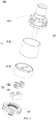
FIG. 3 is an exploded view of the atomizer inFIG. 2 ; -
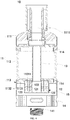
FIG. 4 is a cross-sectional view of the atomizer along C-C inFIG.2 ; -
FIG.5 is an enlarged isometric view of a base in the atomizer; -
FIG. 6 is an enlarged isometric view of a heating component in the atomizer. - With reference to
FIG. 1 to FIG. 6 ,1 represents the electronic cigarette, 10 represents the atomizer, 11 represents the liquid storage chamber, 111 represents the top cover, 1111 represents the first through hole, 112 represents the shell, 113 represents the fixing base, 1131 represents the basal portion, 11311 is the liquid conductive hole, 11312 is the second air hole, 11313 is the groove, 1132 is the extending portion, 114 is the sealing glue, 12 is the heating component, 121 is the case, 1211 is the second through hole, 1212 is the slot, 122 is the heating element,1221 is the heating box, 12211 is the heating compartment, 1222 is an absorption element; 1223 is the heating area; 1224 is the first through hole; 123 is the liquid storage sump; 13 is the air pipe, 14 is the base, 141 is the threaded connector, 15 is the case, 20 is the power supply. - The structure and operating principle of the above heating element with temperature control and the low-temperature baked smoking set having same are illustrated below, mainly shown from
FIG. 1 to FIG. 12 in further detail using exemplary embodiments. - Referring to
FIG. 1 , which is an aspect view of an electronic cigarette in accordance with one embodiment of the present disclosure. The electronic cigarette includes: anatomizer 10 and apower supply 20, thepower supply 20 is couple with theatomizer 10 to supply power to theatomizer 10, allowing theatomizer 10 to heat the tobacco liquid for atomization, to generate an aerosol. - More specifically, the
power supply 20 is detachably connected with theatomizer 10 via a threadedconnector 141. Of course, in some alternative embodiments, thepower supply 20 and theatomizer 10 may be coupled via other methods, such as snap fit and rivet joint etc. - Furthermore, with reference to
FIG. 2 to FIG. 6 , which illustrate the structures of the atomizer in accordance with the embodiments of the present disclosure, theatomizer 10 includes: aliquid storage chamber 11, aheating component 12, anair pipe 13 and abase 14. - The
liquid storage chamber 11 is connected with thebase 14 and theliquid storage chamber 11 is located above thebase 14. Between theliquid storage chamber 11 and thebase 14 has acase 15 formed there-between. Theheating component 12 is connected with theliquid storage chamber 11 and theheating component 12 is disposed in thecase 15; that means theheating component 12 is disposed between theliquid storage chamber 11 and thebase 14. Theair pipe 13 is passing through theliquid storage chamber 11 and one end of theair pipe 13 is communicated with theheating component 12, enabling an aerosol generated by that theheating component 12 heats the tobacco liquid, to pass through theair pipe 13 so as to supply to the user. - As used herein, the
liquid storage chamber 11 includes ashell 112, atop cover 11 and a fixingbase 113; thetop cover 11, theshell 112 and the fixingbase 113 are successively connected from top to bottom. - More specifically, the
top cover 111 has a first throughhole 1111, the first throughhole 1111 is a round-shaped through hole, passing through thetop cover 111, located at a middle of thetop cover 111, that is, the central axial of the first throughhole 1111 is coaxial with the central axial of thetop cover 111. - Referring to
FIG. 5 , which is an enlarged isometric view of a base in the atomizer. The fixingbase 113 includes abasal portion 1131 and an extendingportion 1132 extending from thebasal portion 1131. - The
basal portion 1131 is a cylinder; thebasal portion 1131 of the fixingbase 113 is bored with aliquid conducting hole 11311, asecond air hole 11312 and agroove 11313. Specifically, thegroove 11313 is positioned at a central of the bottom of thebasal portion 1131. Thegroove 11313 is a rectangular-shaped groove, sinking upwards rather than passing through thebasal portion 1131 and configured for installing theheating component 12. Thebasal portion 1131 has theliquid conducting hole 11311 and thesecond air hole 11312 bored thereon, corresponding with thegroove 11313. Theliquid conducting hole 11311 and thesecond air hole 11312 opened on thebasal portion 1131 are both communicated with the groove 11313.Theliquid conducting hole 11311 and thesecond air hole 11312 don't extend within thegroove 11313. Thesecond air hole 11312 is a round-shaped air hole, located at a central of thebasal portion 1131, corresponding with thefirst air hole 1111, that means, the central axes of thefirst air hole 1111 and thesecond air hole 11312 are coaxial with each other. Theliquid conducting hole 11311 is a rectangular-shaped through hole. The number of theliquid conducting hole 11311 is at least one, in the embodiments of the present disclosure, the number of theliquid conducting holes 11311 is four, each side of the second throughhole 11312 has two of the four liquid conductingholes 11311 disposed symmetrically. - The extending
part 1132 is a cylinder-structure, the fixingbase 113 is rivet jointed with thebase 14 via the extendingpart 1132, with the base 14 to form thecase 15. - The
shell 112 is a cylindrical structure, one end of theshell 112 is rivet jointed with thetop cover 111 via a sealingglue 114; an opposite end of theshell 112 is rivet jointed with thebasal portion 1131 via the sealingglue 114; aliquid storage chamber 11 formed by sealing connection of theshell 112, thetop cover 111 and the fixingbase 113, is configured for storing tobacco liquid, so theshell 112 is generally made by transparent materials, such as, glasses, which is convenient for users to see-through. - Furthermore, the
heating component 12 is a core of theatomizer 10 heating the tobacco liquid, which includes: acase 121 and at least oneheating element 122. The at least oneheating element 122 is received in thecase 121. And aliquid storage sump 123 is formed between theheating element 122 and thecase 121 or betweenadjacent heating elements 122. Theliquid storage sump 123 is configured for storing some of tobacco liquid leaking from theheating element 122, causing theheating element 122 to heat the leaking tobacco liquid stored in theliquid storage sump 123 to generate an aerosol. - The
case 121 is rectangular-shaped, the size thereof is the same as the size of thegroove 11313, enabling theheating component 12 to be installed in thegroove 11313, thecase 121 is rivet joint with thegroove 11313, moreover, the inside of thecase 121 is communicated with thesecond air hole 11312. - Two opposite side walls of the
case 121 have the second throughholes 1211 opposite with each other, the side wall is bounded by the intersection of a width and a height, P1 and P2 shown inFIG. 6 . The second throughholes 1211 are configured for allowing exterior air to flow into thecase 121. As used herein, the number of the second throughholes 1211 is at least one, and position of each second throughhole 1211 is higher than the bottom of theliquid storage sump 123, making theliquid storage sump 123 capable of storing a certain amount of tobacco liquid, meanwhile avoiding the tobacco liquid in theliquid storage sump 123 leaking outside through the second throughholes 1211. In the embodiment of the present disclosure, the number of the second throughholes 1211 is seven. - Inner side walls of the
case 121 have another set ofslots 1212 opposite with each other, the side wall is bounded by the intersection of a length and a height, P3 and P4 as shown inFIG. 6 . The number of set ofslots 1212 has at least one set, twoopposite slots 1212 works as one set. In the embodiment of the present disclosure, the number of sets ofslots 1212 is four, extending along a length direction of thecase 121 and symmetrically disposed on the length of thecase 121. The position of theslot 1212 is corresponding with the position of theliquid conducting hole 11311 bored on the fixingbase 113. Theslot 1212 is configured for fixing theheating element 122, allowing theheating element 122 to be entirely received in thecase 121; and when theheating element 12 is connected with theliquid storage chamber 11, theheating element 122 is corresponding with theliquid conducting hole 11311. - The
heating element 122 is disposed below theliquid storage chamber 11 and corresponding with theliquid conducting hole 11311, the number of theheating elements 122 is the same as the number of theliquid conducting holes 11311, by controlling the number of theheating elements 122, the amount of the aerosol generated by theelectronic cigarette 1 is controlled. A first throughhole 1224 passing through theheating element 122 is bored on the side wall of theheating element 122, the number of the first throughholes 1224 is at least one, configured for guiding the aerosol generated by atomization to outside theheating element 122. Furthermore, when the first throughhole 1224 is received in thecase 121, the first throughhole 1224 is corresponding with the second throughhole 1211, that means the number of the first throughhole 1224 is the same as the number of the second throughhole 1211. Meanwhile, each of the first thoughholes 1224 has a corresponding position with each of the second throughholes 1211. The first throughhole 1224 and the second throughhole 1211 form an air pipe. When users draw, the exterior air pipe flow into thecase 121 via the first throughhole 1211, afterwards flowing into the second throughhole 1224 and bringing the aerosol generated by atomizing the tobacco liquid to outside theheating element 122, further bringing the aerosol to the second throughhole 11312 and flowing upwards, eventually drawn via the first throughhole 1111 into the user's mouth. The number of the first throughholes 1224 and the second throughholes 1211 affect the flowing amount of the exterior airflow, thus affecting the amount of the aerosol. - Furthermore, each
heating element 122 includes: aheating box 1221, aheating area 1223 and anabsorption element 1222. - The
heating box 1221 is rectangular, generally made by metallic or ceramic etc. some good heat conductive materials. The size of theheating box 1221 is corresponding with the size of thecase 121. More specifically, the height of theheating box 1221 is the same as the height of thecase 121, and the breadth of theheating box 1221 is the same as the breadth of theslot 1212 opened on thecase 121; the length of theheating box 1221 is the same as a distance between twoopposite slots 1212 so theheating box 1221 is capable of being fixed in thecase 121, as well as forming theliquid storage sump 123 with thecase 121. Moreover, when theheating box 1221 is received in thecase 121, P1 side is opposite with p1 side inFIG. 6 , that is, the side having the first throughhole 1211 is opposite with the side having the second throughhole 1224. - A
heating compartment 12211 is formed inside theheating box 1221, an opening above theheating compartment 12211 is communicated with a top of theheating compartment 12211; when theheating compartment 12211 is fixed in thecase 121 and theheating component 12 is connected with theliquid storage chamber 11, the opening above theheating compartment 12211 is corresponding with the liquidconductive hole 11311 and the size of theheating compartment 12211 is not less than the size of the liquidconductive hole 11311, enabling the tobacco liquid in theliquid storage chamber 11 entirely flowing into theheating compartment 12211 through the liquidconductive hole 11311. - The
heating area 1223 is a resistive circuit printed on outside or inside surface of theheating box 1221. Theheating area 1223, that is the resistive circuit, heats theheating box 1221 after provided by electricity, thus theheating box 1221 may heat the tobacco liquid. More specifically, in embodiments, theheating area 1223 is disposed on the p1 side of theheating box 1221, resembling a letter "C". Of course, in some alternative embodiments, theheating area 1223 may be set on other sides of theheating box 1221, not only one side but also multiple sides, shaped as back wire etc. Understandable, theheating area 1223 is also a heating layer coating on a surface of theheating box 1221, also a heating piece, a heating wire or a heating net etc. being sintered with theheating box 1221 as a whole. - The
absorption element 1223 may be made by fiber materials, which is filled in the heating compartment in theheating box 1221, being capable of guiding tobacco liquid towards a vicinity of theheating box 1221 for heating. When theheating component 12 is connected with theliquid storage chamber 11, theabsorption element 1222 contacts the liquidconductive hole 11311, enabling the tobacco liquid in theliquid storage chamber 11 to pass through the liquidconductive hole 11311 into theabsorption element 1222. - Understandable, in terms of the
heating component 12, firstly, printing theheating area 1223 on theheating box 1221, then filling theabsorption element 1222 into the heating compartment in theheating box 1221 so that aheating element 122 is formed; afterwards, installing theheating elements 122 into correspondingslots 1212 according to the number and position of the liquidconductive holes 11311 thus theheating component 12 is formed, in this case, in theheating component 12, the first throughhole 1224 is corresponding with the second throughhole 1211 to form the air pipe, and theliquid storage sump 123 is formed by theheating elements 122, theheating box 1221 andadjacent heating elements 122, for storing some of tobacco liquid leaking from theheating elements 122; eventually, rivet jointing thecomponent 12 with thegroove 11313 in theliquid storage chamber 11. As described herein, theheating element 122 is disposed below the liquidconductive hole 11311, and theabsorption element 122 of theheating element 122 contacts the liquidconductive holes 11311 of theliquid storage chamber 11, thus the tobacco liquid from theliquid storage chamber 11 may flow into theabsorption element 1222 through the liquidconductive holes 11311, furthermore, guided by theabsorption element 1222 to the vicinity of theheating box 1221 for atomization. - Furthermore, the
air pipe 13 is a cylindrical structure, one end of theair pipe 13 is fixed in thefirst air hole 1111 bored on thetop cover 111, an opposite end of theair pipe 13 is fixed in thesecond air hole 11312 of the fixingbase 113. Theair pipe 13 fixed in thesecond air hole 11312 is partially extending into thecase 121, thus communicated with inside of thecase 121 and enabling the aerosol generated by theheating element 122 to be drawn by the user via theair pipe 13. As used herein, theair pipe 13 is hermetically connected with thefirst air hole 1111 and thesecond air hole 11312, thus preventing leakage of the tobacco liquid. - Furthermore, the
base 14 is connected with the fixingbase 113 in theliquid storage chamber 11. More specifically, thebase 14 is rivet connected with the extendingpart 1132 of the fixingbase 113. Thebase 14 has an air inlet apparatus (not shown), when the user draws theelectronic cigarette 1, exterior air is carrying the aerosol generated by theheating component 12 to form airflow in the air pipe of theelectronic cigarette 1, further the airflow is drawn out. With the air inlet apparatus, the amount of the exterior air flowing to theelectronic cigarette 1 is controlled, thus the amount of airflow drawn out is controlled. - The bottom of the
base 14 is provided with a threadedconnector 141. Theatomizer 10 is coupled with thepower supply 20 via the threadedconnector 141 on thebase 14. - Overall, understandable, when assembling the
atomizer 10, firstly, assembling theheating component 12 containing: printing theheating area 1223 on theheating box 1221, then filling theabsorption element 1222 in theheating compartment 12211 of theheating box 1221 to assemble theheating component 122; then fixedly connecting theair pipe 13 with thefirst air hole 1111 bored on thetop cover 111, then thetop cover 111 is rivet connected with one end of theshell 112 via a sealingglue 114; an opposite end of theshell 112 is rivet connected with thebasal part 1131 of the fixingbase 113 via the sealingglue 114. In this case, thesecond air hole 11312 bored on thebasal part 1131 of the fixingbase 113 is fixedly connected with an opposite end of theair pipe 13; at last, rivet connecting theheating component 12 with thegroove 11313 on thebasal part 1131 of the fixingbase 113, in this case, theair pipe 13 is communicated with theheating component 12, theheating element 122 is disposed below the liquidconductive hole 11311, while theabsorption element 1222 of theheating element 122 contacts the liquidconductive hole 11311. Thus the tobacco liquid in theliquid storage chamber 11 may flow towards theabsorption element 1222 by gravity, and through the liquidconductive hole 11311, then theabsorption element 1222 guides the tobacco liquid to the vicinity of theheating box 1221 to generate the aerosol. The leaked tobacco liquid may flow towards theheating component 12 by gravity to be stored in theliquid storage sump 123, can't be leaked to theair pipe 13. Since the tobacco liquid in theliquid storage sump 123 is near to theheating element 122, the tobacco liquid may be heated by theheating element 122 to generate the aerosol that is supplied to the user by theair pipe 13, which effectively avoids the user to draw the tobacco liquid. Ultimately, thebase 14 is rivet connected with the extendingpart 1132 of the fixingbase 113 to assemble theatomizer 10. - The
atomizer 10 is coupled with thepower supply 20 via the threadedconnector 141 to assemble theelectronic cigarette 1. - After the
atomizer 10 is supplied power via thepower supply 20, theheating element 122 heats to the tobacco liquid stored in theabsorption element 1222 to generate the aerosol, while the leaked tobacco liquid, stored in theliquid storage sump 123, is heated to generate the aerosol, so that the leaked tobacco liquid may be consumed, effectively avoids a problem of the user drawing the tobacco liquid. The generated aerosol flows from theheating component 12 into theair pipe 13, when the user draws the mouth piece, the aerosol in theair pipe 13 is drawn to the user's mouth through thefirst air hole 1111. - Additional aspects and advantages of the present disclosure will be: the present disclosure relates to an atomizer and an electronic cigarette having same; the atomizer includes a liquid storage chamber and a heating component. The heating component includes a heating element and a case, the heating element is received in the case and a liquid storage sump is formed there-between. As used herein, the heating component is connected with the liquid storage chamber and the heating element is disposed above the liquid conductive hole so that the tobacco liquid stored in the liquid storage chamber will flow by gravity, towards the heating element for atomization. Furthermore, even though leakage of the tobacco liquid exists, the leaking tobacco liquid would flow towards the heating component, stored in the liquid storage sump of the heating component, thus the leaking tobacco is only capable of being stored in the heating component and can't leak to the inside air pipe of the atomizer, which effectively avoids the tobacco liquid to be drawn by the user, enhancing the user experience.
- Terminology used herein is for the purpose of describing particular embodiments only and is not intended to be limiting of the invention. Variations may be made to the embodiments and methods without departing from the spirit of the disclosure. Accordingly, it is appropriate that the appended claims be construed broadly and in a manner consistent with the scope of the disclosure.
Claims (12)
- A heating device comprising:a liquid storage chamber (11) configured for storing tobacco liquid; the liquid storage chamber (11) comprising a liquid conducting hole (11311);a heating component (12) comprising at least one heating element (122) and a case (121); the at least one heating element (122) being received in the case (121);a liquid storage sump (123) between the heating element (122) and the case (121) or between the adjacent heating elements (122);the heating component (12) being connected with the liquid storage chamber (11);the heating element (122) being disposed under the liquid storage chamber (11) and corresponding with the liquid conductive hole (11311);the tobacco liquid in the liquid storage chamber (11) flowing towards the heating element (122) through the liquid conductive hole (11311); the heating element (122) being configured for heating the tobacco liquid for atomization; andthe liquid storage sump (123) configured for storing some of tobacco liquid leaking from the heating element (122), so that the heating element (122) atomizes the tobacco liquid in the liquid storage sump (123).
- The heating device of claim 1, being an atomizer.
- The atomizer of claim 2, wherein the heating element (122) comprises:a heating box (1221) made by heat conductive materials, the heating box (1221) comprising a heating compartment (12211) formed therein, an upper opening of the heating box (1221) being corresponding with the liquid conductive hole (11311);a heating area (1223), formed on the heating box (1221); andan absorption element (1222), filled in the heating compartment (12211); the absorption element (1222) contacting the liquid conductive hole (11311).
- The atomizer of claim 3, wherein
the heating box (1221) is made by ceramic materials; the heating area (1223) is a resistive circuit printed on an outside or inside surface of the heating box (1221). - The atomizer of claim 3, wherein
a first through hole (1224) is bored on a lateral of the heating element (122), the first through (1224) extending through the heating element (122) and being configured for guiding an aerosol generated by atomizing the tobacco liquid to outside of the heating element (122);
the case (121) comprises a second through hole (1211) bored thereon, the second through hole (1211) being configured for guiding exterior air into the case (121);
the heating element (122) is received in the receiving case (121); the first through hole (1224) and the second through hole (1211) are communicated with each other to form an air passage. - The atomizer of claim 5, wherein a total number of the first through holes (1224) is at least one; a total number of the second through holes is at least one; and a position of each second through hole bored is higher than a bottom of the liquid storage sump (123).
- The atomizer of claim 2, wherein the atomizer further comprises an air pipe (13) passing through the liquid storage chamber (11), wherein one end of the air pipe (13) is communicated with inside the case (121).
- The atomizer of claim 7, wherein the liquid storage chamber (11) further comprises:a shell (112);a top cover (111) connected with one end of the shell (112), wherein a first through hole (1111) is bored on the top cover (111);a fixing base (113) connected with another end of the shell (112), the fixing base (113) comprising a second through hole (11312) communicated with the case (121);wherein one end of the air pipe (13) is fixed inside the second through hole (11312);an opposite end of the air pipe (13) is fixed inside the first through hole (1111).
- The atomizer of claim 8, wherein the liquid conducting hole (11311) is bored on the fixing base (113).
- The atomizer of claim 9, wherein the fixing base (113) further comprises a groove (11313) formed thereon; the groove (11313) is communicated with the liquid conducting hole (11311) and the second through hole (11312); the groove (11313) is configured for installing the heating component.
- The atomizer of any one of claims 2-10, wherein the atomizer (10) further comprises a base (14); wherein the base (14) is connected with the liquid storage chamber (11) to form a case (15); wherein the heating component (12) is disposed in the case (15).
- An electronic cigarette comprising a power supply (20), wherein the electronic cigarette (1) further comprises the atomizer according to any one of claims 2-11 and the power supply (20) is coupled with the atomizer (10) and configured for supplying power to the atomizer (10).
Applications Claiming Priority (1)
| Application Number | Priority Date | Filing Date | Title |
|---|---|---|---|
| CN201820241885.8U CN207870276U (en) | 2018-02-09 | 2018-02-09 | A kind of atomizer and electronic cigarette |
Publications (2)
| Publication Number | Publication Date |
|---|---|
| EP3469937A2 true EP3469937A2 (en) | 2019-04-17 |
| EP3469937A3 EP3469937A3 (en) | 2019-08-07 |
Family
ID=63498758
Family Applications (1)
| Application Number | Title | Priority Date | Filing Date |
|---|---|---|---|
| EP19155989.7A Pending EP3469937A3 (en) | 2018-02-09 | 2019-02-07 | Atomizer and electronic cigarette having same |
Country Status (3)
| Country | Link |
|---|---|
| US (1) | US11096422B2 (en) |
| EP (1) | EP3469937A3 (en) |
| CN (1) | CN207870276U (en) |
Cited By (1)
| Publication number | Priority date | Publication date | Assignee | Title |
|---|---|---|---|---|
| EP4074203A4 (en) * | 2019-12-17 | 2023-03-01 | Shenzhen Smoore Technology Limited | ATOMIZER AND ELECTRONIC ATOMIZING DEVICE |
Families Citing this family (8)
| Publication number | Priority date | Publication date | Assignee | Title |
|---|---|---|---|---|
| CN110025055B (en) * | 2019-05-30 | 2024-09-03 | 深圳市庚诚达科技有限公司 | Atomizing device, atomizer and electronic cigarette |
| CN110403246B (en) * | 2019-06-17 | 2022-08-30 | 深圳麦克韦尔科技有限公司 | Electronic atomization device and atomizer thereof |
| CN110101132A (en) * | 2019-06-27 | 2019-08-09 | 广东蜂窝工场电子科技有限公司 | A kind of electronic cigarette cartridge component and electronic cigarette reminded or limit tobacco tar amount |
| CN111743202A (en) * | 2020-07-29 | 2020-10-09 | 深圳市吉迩科技有限公司 | An oil leakage prevention and pressure relief device and an atomizer and electronic cigarette containing the same |
| CN111920100A (en) * | 2020-08-28 | 2020-11-13 | 深圳市吉迩科技有限公司 | Atomizer and aerosol generating device of leak protection oil |
| CN112841739A (en) * | 2021-04-14 | 2021-05-28 | 深圳市讴可电子科技有限公司 | Electronic cigarette |
| CN115590249A (en) * | 2021-06-28 | 2023-01-13 | 深圳市合元科技有限公司(Cn) | Atomizer and aerosol-generating device |
| CN114617306B (en) * | 2022-01-26 | 2025-09-30 | 深圳雪雾科技有限公司 | Power supply components and electronic atomization devices |
Family Cites Families (8)
| Publication number | Priority date | Publication date | Assignee | Title |
|---|---|---|---|---|
| US3270182A (en) * | 1964-03-26 | 1966-08-30 | Hynes Electric Heating Company | High temperature fluid heater |
| US3882934A (en) * | 1972-06-02 | 1975-05-13 | Aga Ab | Heat exchanger |
| US3782456A (en) * | 1972-11-30 | 1974-01-01 | Gusmer Frederick Emil | Heat exchange with resilient liquid accumulator |
| US9982341B2 (en) * | 2015-01-30 | 2018-05-29 | Lam Research Corporation | Modular vaporizer |
| KR20240131476A (en) | 2015-09-01 | 2024-08-30 | 에이와이알 리미티드 | Electronic vaporiser system |
| CN105394816B (en) * | 2015-10-22 | 2018-12-21 | 深圳麦克韦尔股份有限公司 | Electronic cigarette and its atomizing component and nebulising element |
| CN205865985U (en) * | 2016-08-02 | 2017-01-11 | 卓尔悦欧洲控股有限公司 | Atomising head, atomizing device and electron cigarette |
| CN107080289A (en) | 2017-05-06 | 2017-08-22 | 冷朝阳 | The atomizer and atomization core of electronic cigarette |
-
2018
- 2018-02-09 CN CN201820241885.8U patent/CN207870276U/en active Active
-
2019
- 2019-02-07 EP EP19155989.7A patent/EP3469937A3/en active Pending
- 2019-02-07 US US16/269,574 patent/US11096422B2/en active Active
Non-Patent Citations (1)
| Title |
|---|
| None |
Cited By (2)
| Publication number | Priority date | Publication date | Assignee | Title |
|---|---|---|---|---|
| EP4074203A4 (en) * | 2019-12-17 | 2023-03-01 | Shenzhen Smoore Technology Limited | ATOMIZER AND ELECTRONIC ATOMIZING DEVICE |
| US12446627B2 (en) | 2019-12-17 | 2025-10-21 | Shenzhen Smoore Technology Limited | Atomizer and electronic atomization device |
Also Published As
| Publication number | Publication date |
|---|---|
| US11096422B2 (en) | 2021-08-24 |
| US20190246694A1 (en) | 2019-08-15 |
| EP3469937A3 (en) | 2019-08-07 |
| CN207870276U (en) | 2018-09-18 |
Similar Documents
| Publication | Publication Date | Title |
|---|---|---|
| US11096422B2 (en) | Atomizer and electronic cigarette having same | |
| CN211746950U (en) | Atomizer and its aerosol generating device | |
| US11406134B2 (en) | Atomizer and electronic cigarette having same | |
| CN206651392U (en) | Atomising head, atomizer and electronic cigarette | |
| CN203851804U (en) | Atomization device of electronic cigarette and electronic cigarette | |
| CN217722682U (en) | Atomizer and electronic cigarette | |
| CN106418728A (en) | Atomizer and electronic cigarette thereof | |
| JP2021511021A (en) | Steam supply equipment and systems | |
| CN208875410U (en) | Electronic cigarette | |
| CN212590294U (en) | Electronic atomization device and atomizer | |
| CN207285194U (en) | Electronic smoke atomizer | |
| WO2023274084A1 (en) | Atomizer and aerosol generating device | |
| CN108618204A (en) | Atomizer and electronic cigarette | |
| CN104856233A (en) | Smoke generation device and electronic cigarette employing same | |
| CN216821747U (en) | Atomizer with double atomizing cores and electronic atomizing device | |
| CN115486571A (en) | Atomizer and electronic cigarette | |
| CN109259325B (en) | Electronic cigarette atomizer | |
| CN220211948U (en) | Atomization structure, atomizer and aerosol generating device | |
| CN219645076U (en) | Multiple-generator atomizing device capable of synchronously switching air flow and output power | |
| CN218605046U (en) | Atomizer and electronic atomization device | |
| CN218219157U (en) | Atomizers and Electronic Cigarettes | |
| CN216906853U (en) | Atomizing core structure, atomization component and electron cigarette | |
| CN218790560U (en) | Aerosol generating device | |
| CN111759009A (en) | Ultrasonic electronic cigarette atomizing core, atomizer and ultrasonic electronic cigarette | |
| CN208030269U (en) | A kind of electronic cigarette of exportable big amount of smoke |
Legal Events
| Date | Code | Title | Description |
|---|---|---|---|
| PUAI | Public reference made under article 153(3) epc to a published international application that has entered the european phase |
Free format text: ORIGINAL CODE: 0009012 |
|
| STAA | Information on the status of an ep patent application or granted ep patent |
Free format text: STATUS: REQUEST FOR EXAMINATION WAS MADE |
|
| 17P | Request for examination filed |
Effective date: 20190227 |
|
| AK | Designated contracting states |
Kind code of ref document: A2 Designated state(s): AL AT BE BG CH CY CZ DE DK EE ES FI FR GB GR HR HU IE IS IT LI LT LU LV MC MK MT NL NO PL PT RO RS SE SI SK SM TR |
|
| AX | Request for extension of the european patent |
Extension state: BA ME |
|
| PUAL | Search report despatched |
Free format text: ORIGINAL CODE: 0009013 |
|
| AK | Designated contracting states |
Kind code of ref document: A3 Designated state(s): AL AT BE BG CH CY CZ DE DK EE ES FI FR GB GR HR HU IE IS IT LI LT LU LV MC MK MT NL NO PL PT RO RS SE SI SK SM TR |
|
| AX | Request for extension of the european patent |
Extension state: BA ME |
|
| RIC1 | Information provided on ipc code assigned before grant |
Ipc: A24F 47/00 20060101AFI20190704BHEP |
|
| STAA | Information on the status of an ep patent application or granted ep patent |
Free format text: STATUS: EXAMINATION IS IN PROGRESS |
|
| 17Q | First examination report despatched |
Effective date: 20200701 |