EP3469552B1 - Material-aware three-dimensional scanning - Google Patents
Material-aware three-dimensional scanning Download PDFInfo
- Publication number
- EP3469552B1 EP3469552B1 EP17723796.3A EP17723796A EP3469552B1 EP 3469552 B1 EP3469552 B1 EP 3469552B1 EP 17723796 A EP17723796 A EP 17723796A EP 3469552 B1 EP3469552 B1 EP 3469552B1
- Authority
- EP
- European Patent Office
- Prior art keywords
- property
- generating
- map
- particular portion
- image
- Prior art date
- Legal status (The legal status is an assumption and is not a legal conclusion. Google has not performed a legal analysis and makes no representation as to the accuracy of the status listed.)
- Active
Links
Images

Classifications
-
- G—PHYSICS
- G06—COMPUTING OR CALCULATING; COUNTING
- G06T—IMAGE DATA PROCESSING OR GENERATION, IN GENERAL
- G06T15/00—Three-dimensional [3D] image rendering
- G06T15/04—Texture mapping
-
- G—PHYSICS
- G06—COMPUTING OR CALCULATING; COUNTING
- G06T—IMAGE DATA PROCESSING OR GENERATION, IN GENERAL
- G06T11/00—Two-dimensional [2D] image generation
- G06T11/10—Texturing; Colouring; Generation of textures or colours
-
- G—PHYSICS
- G06—COMPUTING OR CALCULATING; COUNTING
- G06T—IMAGE DATA PROCESSING OR GENERATION, IN GENERAL
- G06T2215/00—Indexing scheme for image rendering
- G06T2215/16—Using real world measurements to influence rendering
-
- G—PHYSICS
- G06—COMPUTING OR CALCULATING; COUNTING
- G06T—IMAGE DATA PROCESSING OR GENERATION, IN GENERAL
- G06T2219/00—Indexing scheme for manipulating 3D models or images for computer graphics
- G06T2219/20—Indexing scheme for editing of 3D models
- G06T2219/2012—Colour editing, changing, or manipulating; Use of colour codes
Definitions
- the present disclosure is generally related to three-dimensional (3D) scanning.
- wireless telephones such as mobile and smart phones, tablets and laptop computers that are small, lightweight, and easily carried by users.
- These devices can communicate voice and data packets over wireless networks.
- many such devices incorporate additional functionality such as a digital still camera, a digital video camera, a digital recorder, and an audio file player.
- such devices can process executable instructions, including software applications, such as a web browser application, that can be used to access the Internet. As such, these devices can include significant computing capabilities.
- Wireless telephones unmanned vehicles (e.g., drones), robots, aircraft, automobiles, mounted cameras, personal cameras, and other devices may be configured to capture images. Such images may be used to generate a three-dimensional (3D) model of an object.
- a texture map generator may generate a two-dimensional (2D) texture map that is used for photorealistic rendering of the 3D model.
- the texture map generator typically determines color information (e.g., RGB color information) associated with the object based on a sequence of image frames, and the 2D texture map is typically generated based on the color information.
- the texture map generator may determine that a particular portion of the object is red (R), green (G), blue (B), or a combination thereof. Based on the color, the texture map generator may generate a 2D texture map in which the associated color of the particular portion is represented.
- the 2D texture map may not adequately reflect other properties of the object.
- the 2D texture map may not adequately portray the transparency of the object, the material of the object, surface properties (e.g., bumpiness, smoothness, etc.) of the object, light emission properties of the object, a bidirectional reflectance distribution function (BRDF), etc.
- BRDF bidirectional reflectance distribution function
- a 2D texture map that only includes the color of the object may not adequately portray other properties that allows for more photorealistic rendering by a software renderer or a hardware renderer.
- US 7,589,723 describes real-time rendering of partially translucent objects using a set of parameter maps derived from data measuring reflectance and transmittance of light received at the surface of the partially translucent object in which data is captured from an actual object being modeled.
- US 9,330,494 describes a material property determination system and an automated method of assigning material properties to image textures within a 3D model by comparing image textures to entries in a palette of images representing material entries and assigning the image representing the material palette entry that best matches the one contained in the 3D model image texture.
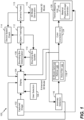
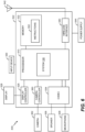
- FIG. 1 is a block diagram of a system 100 configured to generate one or more two-dimensional (2D) texture maps of an object.
- the system 100 generates one or more 2D texture maps of an object based on a set of captured images 102.
- the set of captured images 102 may include a sequence of image frames captured by an image capture device, such as a two-dimensional camera (2D) camera, a 3D camera, a 3D sensor, a depth-sensing camera (e.g., a Red-Green-Blue-Depth (RGB-D) camera), or any other device configured to capture images.
- an image capture device such as a two-dimensional camera (2D) camera, a 3D camera, a 3D sensor, a depth-sensing camera (e.g., a Red-Green-Blue-Depth (RGB-D) camera), or any other device configured to capture images.
- RGB-D Red-Green-Blue-Depth
- multiple cameras may be used by the image capture device to obtain
- the image capture device may be associated with a display 104 which may present (e.g., visually display) a representation of a 3D model based on the captured images 102.
- the displayed representation of the 3D model may be configured to enable a user to correct or enhance a 3D model after initial generation of the 3D model.
- the captured images 102 may include multiple images (e.g., 2D images, 3D images, image data, etc.) representative of a scene.
- the scene may include one or more objects as well as background or other context of the one or more objects.
- One or more of the captured images 102 may be represented via the display 104.
- the display 104 (or another user interface, such as a projector) may present the images to the user.
- the display 104 and/or another user interface, such as a keypad or a button) may be configured to enable the user to provide input related to the images.
- the display 104 may receive a user selection 106.
- the user selection 106 may enable the user to select a region of interest that includes a particular object within the scene.
- the user selection 106 may include information specifying a bounding box around a particular object within the scene.
- the bounding box may correspond to a region of interest defined by the user.
- the region of interest may be displayed relative to one or more of the captured images at the display 104.
- a region of interest defined by the user may be used by a bounding box determination module 108 to determine a bounding box.
- the bounding box may be associated with the object in a three-dimensional model (e.g., a two-dimensional representation of the object) based on the captured images 102.
- the bounding box may include or correspond to the region of interest based on object tracking as the camera moves relative to the object.
- the bounding box may correspond to a cube or other geometric region in three dimensions that corresponds to or includes a portion (e.g., a volume) of the region of interest defined by the user via the display 104.
- an object tracking module 112 may be used to track the region of interest or an object corresponding to the region of interest from one image frame to subsequent image frames.
- the bounding box may be updated, at a bounding box update module 110. For example, during generation of the three-dimensional model when the camera moves closer to or further from the object, a size parameter of the bounding box may be adjusted based on the object tracking.
- the bounding box may be associated with multiple size parameters (e.g., (x, y, z) dimension parameters, a center point (x, y, z) coordinate and a spherical radius, etc.).
- a particular size parameter may be associated with or correspond to a particular dimension of the bounding box (e.g., length, width, or depth).
- the value of the size parameter may be adjusted based on determining that the object is larger or smaller in the bounding box in one image than in a previous image.
- the sequence of images may be used to determine camera poses 113 (e.g., camera pose data).
- the object tracking module 112 may be configured to determine a camera pose of the image capture device when the image capture device is associated with a 3D scan of an object.
- the camera poses 113, the object tracking module 112, or both, may be used to determine a device speed.
- a device speed check unit 114 may determine a speed of the image capture device relative to the object based on a plurality of camera poses, based on a plurality of timestamps associated with the camera poses, or both.
- the speed may be determined based on a calculation of a relative position of a camera corresponding to each camera pose and a timestamp associated with the camera pose.
- a notification may be presented via the display 104.
- the speed may satisfy the speed threshold when the speed is greater than or equal to the speed threshold.
- the speed may satisfy the speed threshold if the speed is within a range of speeds that correspond to the speed threshold.
- the notification may suggest that the speed of the image captured device should be reduced because the speed is greater than or equal to the speed threshold.
- the speed may be reduced in order to reduce errors or to enable more images to be captured within a particular space in order to improve 3D model generation.
- the speed may satisfy the speed threshold when the speed is less than or equal to the speed threshold.
- the speed may be increased to reduce the number of redundant images being captured or to utilize additional processing capacity.
- a notification may be presented via the display 104, and the capture of the sequence of image frames may be paused.
- the second speed threshold and time may indicate a lack of movement (e.g., the camera is not moving or is relatively still). Capturing of the sequence of image frames may be resumed or reinstated when the camera resumes movement.
- the device speed check unit 114 may calculate a speed associated with movement of the image capture device relative to the object and may selectively output a notification via the display 104 based on a comparison of the relative speed of movement of the image capture device to the speed threshold. In response to determining that the speed satisfies the speed threshold, the system 100 may pause capturing of a sequence of images while the notification is provided to the user.
- the camera poses 113 may also be used by the 3D model generation unit 115 to generate a 3D model (e.g., an initial 3D model or a "point cloud").
- An anomaly detection unit 116 may analyze the 3D model to determine whether the 3D model includes an anomaly (e.g., a discontinuity of a surface, a missing or incomplete region, etc.). If the anomaly detection unit 116 detects an anomaly in the 3D model, the anomaly detection unit 116 may cause the display 104 to display an indicator that identifies a location of the anomaly in the 3D model. Alternatively, the indicator may be presented via another user interface (e.g., audio speaker, light emitting diode (LED), etc.). The anomaly detection unit 116 may also provide the 3D model (or data representing the 3D model) to a 3D model optimizer 118.
- an anomaly e.g., a discontinuity of a surface, a missing or incomplete region, etc.
- the anomaly detection unit 116 may
- the 3D model optimizer 118 or the anomaly detection unit 116 may cause the display 104 to present one or more selectable options to enable correction of the anomaly.
- the options are selectable via a display (e.g., the display 104). Alternatively, the options are selectable via one or more other user interfaces (e.g., a speaker, a microphone, a keypad, etc.).
- the options may include an option to activate a refiner unit 120 to enable the system 100 to capture additional images in order to correct the anomaly.
- the options may also include an option to activate a hole filler unit 122 to automatically generate fill data (e.g., based on a hole filling algorithm). If the refiner unit 120 is used to capture additional images, the additional images may be added to the captured images 102 to be processed by other units of the system 100 to generate a new or updated 3D model, which may also be analyzed by the anomaly detection unit 116.
- the 3D model optimizer 118 may be configured to correct pixel values associated with a 3D scan of an object.
- the 3D model optimizer 118 may generate an enhanced 3D model (e.g., enhanced model data), which may be provided to the display 104.
- the enhanced 3D model may also be provided to a color correction unit 124, to a texture mapping unit 126, or to both, to perform color, light, and/or texture corrections based on the captured images 102 in the 3D model to further refine the 3D model for display at the display 104.
- the enhanced 3D model includes more details than the 3D model generated during the capture of the sequence of images. For example, the more details may include higher resolution, improved texture mapping, etc.
- the texture mapping unit 126 is configured to generate one or more 2D texture maps based on a captured image 102.
- the captured image 102 is provided directly to the texture mapping unit 126.
- the texture mapping unit 126 includes a material property image generator 140 that is configured to generate an enhanced image (e.g., a material property image).
- an "enhanced image” includes any image having pixels with values that indicate color and at least one other property.
- Non-limiting examples of the at least one other property may include a transparency quality, a reflection quality, a refraction quality, an ambient quality, a diffusion quality, a subsurface scattering property, etc.
- the material property image generator 140 is configured to generate one or more images of "non-enhanced" pixels.
- the material property image generator 140 may generate a color image, a transparency image, a shininess image, etc.
- a particular pixel in one image has a pixel location (e.g., notated by an x-coordinate and a y-coordinate) that is similar to a pixel location of the particular pixel in another image.
- a particular pixel in the transparency image may have the same pixel location in the shininess image as the transparency image.
- the enhanced image is used by the texture mapping unit 126 to generate a 2D texture map (e.g., a material property texture map).
- a material property texture map include a translucence texture map, a translucence depth texture map, an eccentricity texture map, a normal map, a displacement map, a translucency color texture map, a cosine power map, a specular texture map, a transparency texture map, a bump texture map, a light emission property texture map, a bidirectional reflectance distribution function (BRDF) texture map, etc.
- the BRDF texture map may identify different BRDF functions (e.g., Phong, Lambert, Blinn, Anisotropic, etc.) by a custom identification numbering system.
- the material texture mapping unit 126 is configured to determine a color of a portion of an object using the captured image 102.
- the material property image generator 140 is configured to determine a material of the particular portion of the object using the captured image 102.
- the material property image generator 140 is also configured to determine at least one other property of the particular portion of the object based on the material. For example, in response to identifying the material, the material property image generator 1 accesses a database specifying different properties (e.g., transparency properties, reflection properties, refraction properties, diffusion properties, subsurface scattering properties, etc.) of the material.
- the material property image generator 140 generates a pixel value representative of the color of the particular portion of the object and representative of the at least one other property of the particular portion of the object. Based on the pixel value, the material property image generator 140 generate an enhanced image.
- the texture mapping unit 126 is configured to generate a 2D texture map based on the enhanced image.
- the system 100 of FIG. 1 enables generation of enhanced 2D texture maps that adequately portray non-color properties (in addition to color properties) of an object. For example, by determining a material of the object, the texture mapping unit 126 generates enhanced 2D texture maps that adequately portray a transparency of the object, surface properties (e.g., bumpiness, smoothness, etc.) of the object, light emission properties of the object, etc.
- the enhanced 2D texture maps are used to create a more "life-like" 3D model of the object using computer vision techniques.
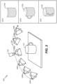
- an illustrative implementation of operation of the system 100 of FIG. 1 is shown and generally designated 200.
- an image capture device 202 e.g., a two-dimensional camera, a depth sensing camera, a three-dimensional camera, etc.
- a path 204 e.g., an arc
- the image capture device 202 is located at various positions and orientations illustrated in FIG. 2 by camera poses 206A, 206B, 206C, 206D, 206E, and 206F.
- the camera poses 206A-F correspond to image capture operations that generate image frames in a sequence of image frames captured by the image capture device 202. It should be noted that the number, separation, and orientation of the camera poses 206A-F shown in FIG. 2 are shown for illustration only, and are not to be considered limiting. For example, more camera poses or fewer camera poses may be used with different intervals between consecutive (or adjacent) camera poses.
- the path 204 may be of any configuration, based on how the image capture device 202 is moved around the object 210.
- a 3D point cloud of the object 210 may be generated in real time or near-real time based on the camera poses 206A-F and the sequence of image frames.
- a first partial 3D point cloud 210A may be generated at the image capture device 202, as shown at 207A.
- additional data may be captured and used to add points to the partial 3D point cloud. For example, when the image capture device 202 has moved along the path 204 to a position associated with the camera pose 206D, a more complete 3D point cloud 210D may be generated, as shown at 207D. After the image capture device 202 reaches a position associated with the camera pose 206F, a completed 3D point cloud 210F may be generated, as shown at 207F.
- FIG. 2 is described with respect to the image capture device 202 moving along the path 204 to capture image frames of a stationary object
- the object or a scene that includes the object
- the object may move relative to a stationary image capture device (e.g., a fixed camera) to generate image frames.
- the object and the image capture device 202 may both move during generation of the image frames.
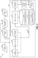
- a texture mapping unit 300 is shown.
- the texture mapping unit 300 includes (or operates in a substantially similar manner as) the texture mapping unit 126 of FIG. 1 .
- the texture mapping unit 300 is implemented in the system 100 of FIG. 1 .
- the texture mapping unit 300 is operable to generate one or more 2D texture maps of an object.
- the texture mapping unit 300 includes a material property image generator 340 and a texture map generator 328.
- the material property image generator 340 includes (or operates in a substantially similar manner as) the material property image generator 140 of FIG. 1 .
- An image frame 302 may be captured by an image capture device (not shown in FIG. 3 ).
- the image frame 302 is captured by the image capture device 202 of FIG. 2 .
- the image frame 302 may be captured while the image capture device 202 is at a position associated with the camera pose 206D.
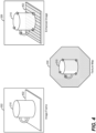
- a depiction of the image frame 302 is shown in FIG. 4 .
- the image frame 302 includes the object 210 of FIG. 2 (e.g., the cup) and an object 402 (e.g., a table).
- the image frame 302 is a color image.
- the image frame 302 may be provided to the material property image generator 340.
- the image frame 302 is provided to the texture map generator 328.
- the material property image generator 340 includes an object recognizer 304, an object isolator 306, a sub-object analyzer 310, a material recognizer 312, a database 314, a pixel value generator 322, and an enhanced image generator 324. According to some implementations, the material property image generator 340 may include fewer (or additional components). According to one implementation, one or more components in the material property image generator 340 may be combined into a single component.
- the object recognizer 304 is configured to receive the image frame 302 from the image capture device.
- the object recognizer 304 is configured to perform object recognition on the image frame 302.
- the object recognizer 304 may identify the object 210 in the image frame 302.
- the object isolator 306 may be configured to isolate the object 210 in the image frame 302 using image segmentation.
- the object isolator 306 may extract the portion of the image frame 302 corresponding to the object 210 and provide the extracted portion (e.g., the object 210) to the material recognizer 312.
- the sub-object analyzer 310 may analyze the image frame 302 to determine whether additional objects are present in the image frame 302, whether the object 210 includes any smaller objects (e.g., "sub-objects"), or a combination thereof. For example, the sub-object analyzer 310 may determine that the object 402 is present in the image frame 302 and may provide data associated with the determination to the object recognizer 304. In response to receiving the data, the object recognizer 304 may identify the object 402 in the image frame 302. In a similar manner as described above, the object isolator 306 may isolate the object 402 in the image frame 302 using image segmentation. For example, the object isolator 306 may extract the portion of the image frame 302 corresponding to the object 402 and provide the extracted portion (e.g., the object 402) to the material recognizer 312.
- the object isolator 306 may isolate the object 402 in the image frame 302 using image segmentation. For example, the object isolator 306 may extract the portion of the image frame 30
- the material recognizer 312 is configured to determine a material of the object 210. To illustrate, the material recognizer 312 accesses the database 314 to identify the material of the object 210 based on the object recognition.
- the database 314 includes first material information 316 associated with a first object, second material information 318 associated with a second object, and Nth material information 320 associated with an Nth object. N may be any integer that is greater than zero. For example, if N is equal to nine, the database 314 may store nine different items of material information associated with nine different objects.
- the material recognizer 312 accesses the database 314 to retrieve the first material information 316 associated with the first object.
- the first material information 316 may indicate the material that the object 210 (e.g., the cup) is comprised of (or the material that similar objects are comprised of).
- the first material information 316 may indicate that a cup is typically comprised of glass.
- the first material information 316 may also indicate properties of the determined material (e.g., glass).
- the first material information 316 may indicate a transparency quality for glass, a reflection quality for glass, a refraction quality for glass, an ambient quality for glass, a diffusion quality for glass, a subsurface scattering property for glass, a property based on a BRDF, or a combination thereof.
- the material recognizer 312 accesses the database 314 associated with different objects to identify the material of the object 210 and properties of the material based on the object recognition.
- the first material information 316 is provided to the pixel value generator 322.
- the material recognizer 312 may determine the material of the object 210 based on detected features of the object 210 without requiring object recognition. For example, object recognition operations (associated with the object recognizer 304, the object isolator 306, and the sub-object analyzer 310) may be bypassed and the material recognizer 312 may detect particular features of the object 210. Based on the detected features, the material recognizer 312 may determine the material of the object 210 and properties of the material. To illustrate, the material recognizer 312 may determine that the object 210 is smooth, shiny, and relatively clear without performing object recognition operations. Based on the features, the material recognizer 312 may determine that the object 210 is made of glass. The material recognizer 312 may use computer vision, machine learning, or a combination thereof, to determine the material of the object 210 while bypassing the object recognition operations.
- object recognition operations associated with the object recognizer 304, the object isolator 306, and the sub-object analyzer 310
- the material recognizer 312 may determine the material of the object 210 and properties of
- the pixel value generator 322 is configured to generate pixel values (for different pixels of the object 210) representative of the color of the object 210 and representative of at least one other property of the object 210.
- the other property of the object 210 may be based on the first material information 316.
- the first material information 316 may indicate that glass is partially transparent.
- the first material information 316 may indicate that glass has a transparency value of four (on a scale from one to ten), where one indicates zero transparency and ten indicates absolute transparency (e.g., clear).
- the first material information 316 may also indicate that glass has a refraction value of five on a scale from one to ten.
- the object 210 e.g., the cup
- the object 210 may appear relatively "shiny" to the human eye after rendering because light may bend when it touches the surface of the cup.
- the pixel value generator 322 may apply the first material information 316 to a red-green-blue-alpha (RGBA) channel.
- the material recognizer 312 may encode all of the properties identified for a particular material using a 32-bit identifier.
- the first material information 316 may be encoded as a first 32-bit identifier
- the second material information 318 may be encoded as a second 32-bit identifier
- the Nth material information 320 may be encoded as an Nth 32-bit identifier.
- the pixel value generator 322 may apply the bit values (e.g., the first 32-bit identifier) to the RGBA channel to generate the pixel values for the object 210.
- the pixel value generator 322 may also apply the bit values of the color information (associated with the color of the object 210) to the RGBA channel to generate the pixel values for the object 210.
- the pixel values may be provided to the enhanced image generator 324 (e.g., the material image generator).
- the enhanced image generator 324 is configured to generate an enhanced image 326 based on the pixel values.
- the object 210 in the enhanced image 326 is shinier than the object 210 in the image frame 302.
- encoding the RGBA channel with the first material information 316 at the pixel value generator 322 may produce pixel values that have a relatively high refraction quality.
- the object 210 in the enhanced image 326 is also more transparent than the object 210 in the image frame 302.
- encoding the RGBA channel with the first material information 316 at the pixel value generator 322 may produce pixel values that portray a relatively high level of transparency.
- the object 402 in the enhanced image 326 also looks different than the object 402 in the image frame 302. For example, the object 402 in the enhanced image looks more "wooden” and "grainier” than the object 402 in the image frame 302. Similar techniques as described with respect to the object 210 in the enhanced image 326 may be used to generate the object 402 in the enhanced image 326.
- the material recognizer 312 may access the database 314 to retrieve the second material information 318 if the second object (associated with the second material information 318) is a table.
- the second material information 318 may indicate the material that the object 402 (e.g., the table) is comprised of (or the material that similar objects are comprised of).
- the second material information 318 may indicate that the material for a table is typically wood.
- the second material information 318 may also indicate properties of the material.
- the second material information 318 may indicate that wood is typically rough (e.g., "grainy") and may indicate other properties (e.g., refraction, transparency, diffusion, etc.) of wood.
- the pixel value generator 322 may generate pixel values (for different pixels of the object 402) representative of the color of the object 402 and representative of at least one other property of the object 402. The other property of the object 402 may be based on the second material information 318.
- the pixel value generator 322 may apply the bit values (e.g., the second 32-bit identifier) to the RGBA channel to generate the pixel values for the object 402, and the enhanced image generator 324 may generate the enhanced image 326 based on the pixel values, as described above.
- the bit values e.g., the second 32-bit identifier
- the material property image generator provides the enhanced image 326 to a texture map generator 328.
- the image frame 302 may also be provided to the texture map generator 328.
- the texture map generator 328 is configured to generate a texture map 330 (e.g., a 2D texture map) based on the enhanced image 326.
- the texture map generator 328 uses the enhanced image 326 (e.g., a "material identification image") to access a set of property values in a database (not shown) and generates the texture map 330 based on the property values.
- the texture map generator 328 may encode a property value for each image pixel in the enhanced image 326 to generate the texture map 330.
- a property value may be a 32-bit floating point number or a 32-bit integer.
- the property values may also be used as proxy values for the 32-bit RGBA color of a pixel.
- a depiction of the texture map 330 is shown in FIG. 4 .
- the texture map 330 may be applied to a 3D model of the object 210 to generate a "real-life" 3D model using computer vision techniques.
- the texture map generator 328 may generate multiple texture maps (based on multiple enhanced images) instead of generating the single texture map 330.
- each enhanced image may be based on a single property, and the texture map generator 328 may generate a texture map for each property.
- the texture map generator 328 may generate a translucence map, a translucence depth map, a specular map, an eccentricity map, a bump map, a normal map, a displacement map, a translucency color map, a cosine power map, or a combination thereof.
- the texture mapping unit 300 of FIG. 3 enables generation of enhanced 2D texture maps that adequately portray non-color properties (in addition to color properties) of an object. For example, by determining a material of the object, the texture mapping unit 300 generates enhanced 2D texture maps that adequately portray a transparency of the object, surface properties (e.g., bumpiness, smoothness, etc.) of the object, light emission properties of the object, etc.
- the enhanced 2D texture maps are used to create a more "life-like" 3D model of the object using computer vision techniques.
- a method 500 of generating one or more 2D texture maps of an object is depicted.
- the method 500 is performed by the texture mapping unit 126 of FIG. 1 , the texture mapping unit 300 of FIG. 3 , or both.
- the method 500 includes receiving an image frame including at least a portion of the object from an image capture device, at 502.
- the image frame 302 may be captured by the image capture device 202.
- the object recognizer 304 may receive the image frame 302 from the image capture device 202.
- a color of a particular portion of the object is determined using the image frame, at 504. For example, referring to FIG. 1 , the color correction unit 124 or the texture mapping unit 126 determines the color of the particular portion of the object 210.
- a material of the particular portion of the object is determined using the image frame, at 506.
- the material recognizer 312 determines the material of the object 210.
- the material recognizer 312 accesses the database 314 to identify the material of the object 210 based on the object recognition.
- the material recognizer 312 accesses the database 314 to retrieve the first material information 316 associated with the first object.
- the first material information 316 may indicate the material that the object 210 (e.g., the cup) is comprised of (or the material that similar objects are comprised of).
- the first material information 316 may indicate that the material of the object 210 is glass.
- Determining the material of the particular portion of the object includes detecting at least one particular feature of the particular portion of the object and determining the material of the particular portion of the object based on the particular feature.
- the material recognizer 312 determines the material of the object 210 based on detected features of the object 210 without requiring object recognition. In an example, which does not form a part of the invetion, object recognition operations may be bypassed and the material recognizer 312 may detect particular features of the object 210. Based on the detected features, the material recognizer 312 may determine the material of the object 210 and properties of the material. To illustrate, the material recognizer 312 may determine that the object 210 is smooth, shiny, and relatively clear without performing object recognition operations. Based on the features, the material recognizer 312 may determine that the object 210 is made of glass.
- At least one other property of the particular portion of the object is determined based on the material, at 508.
- the material recognizer 312 accesses the database 314 to retrieve properties of glass (e.g., properties of the determined material of the object 210).
- the first material information 316 may indicate a transparency quality for glass, a reflection quality for glass, a refraction quality for glass, an ambient quality for glass, a diffusion quality for glass, a subsurface scattering property for glass, a property based on a BRDF, or a combination thereof.
- the material recognizer 312 accesses the database 314 associated with different objects to identify the material of the object 210 and properties of the material based on the object recognition.
- a pixel value representative of the color of the particular portion of the object and representative of the at least one other property of the particular portion of the object is generated, at 510.
- the pixel value generator 322 generates pixel values (for different pixels of the object 210) representative of the color of the object 210 and representative of at least one other property of the object 210.
- the pixel value generator 322 applies material information (e.g., the first material information 316) associated with the material to a RGBA channel and applies color information associated with the color to the RGBA channel.
- At least one two-dimensional texture map is generated based on the pixel value, at 512.
- the enhanced image generator 324 generates the enhanced image 326 based on the pixel value(s)
- the texture map generator 328 generates the texture map 330 based on the enhanced image 326.
- determining the at least one other property of the particular portion of the object includes determining a first property of the particular portion of the object and determining a second property of the particular portion of the object.
- Generating the at least one two-dimensional texture map, at 512 may include generating a first two-dimensional texture map and generating a second two-dimensional texture map. The first two-dimensional texture map may be based on the first property and the second two-dimensional texture map may be based on the second property.
- generating the at least one two-dimensional texture map, at 512 may include generating a two-dimensional texture map associated with the first property and the second property.
- the method 500 of FIG. 5 may enable generation of enhanced 2D texture maps that adequately portray non-color properties (as well as color properties) of an object.
- the texture mapping unit 300 may generate enhanced 2D texture maps that adequately portray a transparency of the object, surface properties (e.g., bumpiness, smoothness, etc.) of the object, light emission properties of the object, etc.
- the enhanced 2D texture maps may be used to create a more "life-like" 3D model of the object using computer vision techniques.
- FIG. 6 a block diagram of a particular illustrative implementation of an electronic device, such as a wireless communication device, is depicted and generally designated 600.
- the device 600 includes a processor 610, such as a digital signal processor (DSP), coupled to a memory 632.
- the processor 610 may include hardware or executable instructions that cause the processor to perform the method 500 of FIG. 5 .
- the processor 610 includes the system 100 of FIG. 1 .
- the memory 632 may be a non-transient or non-transitory computer readable medium storing computer-executable instructions 652 to perform all or a portion of one or more operations described with reference to FIGS. 1-5 .
- FIG. 6 also shows a display controller 626 that is coupled to the digital signal processor 610 and to a display 628, such as the display 104 of FIG. 1 .
- a coder/decoder (CODEC) 634 can also be coupled to the digital signal processor 610.
- a speaker 636 and a microphone 638 can be coupled to the CODEC 634.
- FIG. 6 also indicates that a wireless interface 640 can be coupled to the processor 610 and to an antenna 642.
- a camera 662 may be coupled to the processor 610 via a camera controller 660.
- the camera controller 660 may include interface circuitry that is configured to receive image frames of an object.
- the interface circuitry may correspond to circuitry that receives the captured image frames from the camera 662 and provides the captured image frames to the processor 610.
- the image frames may be associated with a three-dimensional scan of the object.
- the camera 662 may include a 2D camera, a 3D camera, a 3D sensor, a depth-sensing camera (e.g., an RGB-D camera), or any other device configured to capture images.
- the camera 662 may include the image capture device 202 of FIG. 2 .
- the processor 610, the display controller 626, the camera controller 660, the memory 632, the CODEC 634, and the wireless interface 640 are included in a system-in-package or system-on-chip device 622.
- an input device 630 and a power supply 644 are coupled to the system-on-chip device 622.
- the display 628, the input device 630, the speaker 636, the microphone 638, the antenna 642, the camera 662, and the power supply 644 are external to the system-on-chip device 622.
- each of the display 628, the input device 630, the speaker 636, the microphone 638, the antenna 642, the camera 662, and the power supply 644 can be coupled to a component of the system-on-chip device 622, such as an interface or a controller.
- an apparatus for generating one or more two-dimensional texture maps of an object includes means for capturing an image frame that includes at least a portion of the object.
- the means for capturing the image frame may include the image capture device 202 of FIG. 2 , the camera 662 of FIG. 6 , the camera controller 660 of FIG. 6 , one or more other structures, devices, circuits, or a combination thereof.
- the apparatus may also include means for determining a color of a particular portion of the object using the image frame.
- the means for determining the color of the particular portion of the object may include the color correction unit 124 of FIG. 1 , the texture mapping unit 126 of FIG. 1 , the texture mapping unit 300 of FIG. 3 , the processor 610 of FIG. 6 , one or more other structures, devices, circuits, or a combination thereof.
- the apparatus may also include means for determining a material of the particular portion of the object using the image frame.
- the means for determining the material of the particular portion of the object may include the texture mapping unit 126 of FIG. 1 , the texture mapping unit 300 of FIG. 3 , the material recognizer 312 of FIG. 3 , the database 314 of FIG. 3 , the processor 610 of FIG. 6 , one or more other structures, devices, circuits, or a combination thereof.
- the apparatus may also include means for determining at least one other property of the particular portion of the object based on the material.
- the means for determining the at least one other property of the particular portion of the object may include the texture mapping unit 126 of FIG. 1 , the texture mapping unit 300 of FIG. 3 , the material recognizer 312 of FIG. 3 , the database 314 of FIG. 3 , the processor 610 of FIG. 6 , one or more other structures, devices, circuits, or a combination thereof.
- the apparatus may also include means for generating a pixel value representative of the color of the particular portion of the object and representative of the at least one other property of the particular portion of the object.
- the means for generating the pixel value may include the texture mapping unit 126 of FIG. 1 , the texture mapping unit 300 of FIG. 3 , the pixel value generator 322 of FIG. 3 , the processor 610 of FIG. 6 , one or more other structures, devices, circuits, or a combination thereof.
- the apparatus may also include means for generating at least one two-dimensional texture map based on the pixel value.
- the means for generating the 2D texture map may include the texture mapping unit 126 of FIG. 1 , the texture mapping unit 300 of FIG. 3 , the texture map generator 328 of FIG. 3 , the processor 610 of FIG. 6 , one or more other structures, devices, circuits, or a combination thereof.
- a software module may reside in random access memory (RAM), flash memory, read-only memory (ROM), programmable read-only memory (PROM), erasable programmable read-only memory (EPROM), electrically erasable programmable read-only memory (EEPROM), registers, hard disk, a removable disk, a compact disc read-only memory (CD-ROM), or any other form of non-transient storage medium known in the art.
- An exemplary storage medium is coupled to the processor such that the processor can read information from, and write information to, the storage medium.
- the storage medium may be integral to the processor.
- the processor and the storage medium may reside in an application-specific integrated circuit (ASIC).
- ASIC application-specific integrated circuit
- the ASIC may reside in a computing device or a user terminal.
- the processor and the storage medium may reside as discrete components in a computing device or user terminal.
Landscapes
- Engineering & Computer Science (AREA)
- Physics & Mathematics (AREA)
- General Physics & Mathematics (AREA)
- Theoretical Computer Science (AREA)
- Computer Graphics (AREA)
- Image Analysis (AREA)
- Image Processing (AREA)
Description
- The present disclosure is generally related to three-dimensional (3D) scanning.
- Advances in technology have resulted in smaller and more powerful computing devices. For example, there currently exist a variety of portable personal computing devices, including wireless telephones such as mobile and smart phones, tablets and laptop computers that are small, lightweight, and easily carried by users. These devices can communicate voice and data packets over wireless networks. Further, many such devices incorporate additional functionality such as a digital still camera, a digital video camera, a digital recorder, and an audio file player. Also, such devices can process executable instructions, including software applications, such as a web browser application, that can be used to access the Internet. As such, these devices can include significant computing capabilities.
- Wireless telephones, unmanned vehicles (e.g., drones), robots, aircraft, automobiles, mounted cameras, personal cameras, and other devices may be configured to capture images. Such images may be used to generate a three-dimensional (3D) model of an object. Typically, to generate texture maps accompanying the 3D model of the object, a texture map generator may generate a two-dimensional (2D) texture map that is used for photorealistic rendering of the 3D model. The texture map generator typically determines color information (e.g., RGB color information) associated with the object based on a sequence of image frames, and the 2D texture map is typically generated based on the color information. For example, the texture map generator may determine that a particular portion of the object is red (R), green (G), blue (B), or a combination thereof. Based on the color, the texture map generator may generate a 2D texture map in which the associated color of the particular portion is represented.
- However, the 2D texture map may not adequately reflect other properties of the object. As a non-limiting example, the 2D texture map may not adequately portray the transparency of the object, the material of the object, surface properties (e.g., bumpiness, smoothness, etc.) of the object, light emission properties of the object, a bidirectional reflectance distribution function (BRDF), etc. Thus, a 2D texture map that only includes the color of the object may not adequately portray other properties that allows for more photorealistic rendering by a software renderer or a hardware renderer.
-
US 7,589,723 describes real-time rendering of partially translucent objects using a set of parameter maps derived from data measuring reflectance and transmittance of light received at the surface of the partially translucent object in which data is captured from an actual object being modeled. -
US 9,330,494 - The invention is defined in the claims to which reference is now directed.
- Further embodiments are defined in the dependent claims.
-
-
FIG. 1 is a block diagram of a system that is operable to generate one or more two-dimensional (2D) texture maps of an object; -
FIG. 2 is a diagram that illustrates a plurality of camera poses; -
FIG. 3 is a block diagram of a texture mapping unit that is operable to generate one or more 2D texture maps of an object; -
FIG. 4 is a diagram that depicts an image frame, a material property image generated based on the image frame, and a texture map generated based on the material property image; -
FIG. 5 is a flow diagram of a method of generating one or more 2D texture maps of an object; and -
FIG. 6 is a block diagram of a computing device that includes components configured to perform one or more of the techniques, methods, and processes described with respect toFIGS. 1-5 . - Particular implementations of the present disclosure are described with reference to the drawings. In the description, common features are designated by common reference numbers throughout the drawings. The techniques described below are generally applicable to a mobile device. However, it will be appreciated that the techniques are also applicable to an unmanned vehicle (e.g., a drone), a robot, an aircraft, an automobile, a mounted camera, a personal camera, a processing system communicatively coupled to mounted cameras, other devices that are attached to (or included within) a processing device compatible to generate texture maps, etc.
-
FIG. 1 is a block diagram of asystem 100 configured to generate one or more two-dimensional (2D) texture maps of an object. Thesystem 100 generates one or more 2D texture maps of an object based on a set of capturedimages 102. The set of capturedimages 102 may include a sequence of image frames captured by an image capture device, such as a two-dimensional camera (2D) camera, a 3D camera, a 3D sensor, a depth-sensing camera (e.g., a Red-Green-Blue-Depth (RGB-D) camera), or any other device configured to capture images. Alternatively, multiple cameras may be used by the image capture device to obtain the set of capturedimages 102. The image capture device may be associated with adisplay 104 which may present (e.g., visually display) a representation of a 3D model based on the capturedimages 102. The displayed representation of the 3D model may be configured to enable a user to correct or enhance a 3D model after initial generation of the 3D model. - The captured
images 102 may include multiple images (e.g., 2D images, 3D images, image data, etc.) representative of a scene. For example, the scene may include one or more objects as well as background or other context of the one or more objects. One or more of the capturedimages 102 may be represented via thedisplay 104. For example, as a user captures images of the scene using a camera, the display 104 (or another user interface, such as a projector) may present the images to the user. Additionally, the display 104 (and/or another user interface, such as a keypad or a button) may be configured to enable the user to provide input related to the images. For example, thedisplay 104 may receive auser selection 106. Theuser selection 106 may enable the user to select a region of interest that includes a particular object within the scene. - The
user selection 106 may include information specifying a bounding box around a particular object within the scene. The bounding box may correspond to a region of interest defined by the user. The region of interest may be displayed relative to one or more of the captured images at thedisplay 104. A region of interest defined by the user may be used by a boundingbox determination module 108 to determine a bounding box. The bounding box may be associated with the object in a three-dimensional model (e.g., a two-dimensional representation of the object) based on the capturedimages 102. For example, the bounding box may include or correspond to the region of interest based on object tracking as the camera moves relative to the object. - The bounding box may correspond to a cube or other geometric region in three dimensions that corresponds to or includes a portion (e.g., a volume) of the region of interest defined by the user via the
display 104. As the camera continues to capture images, anobject tracking module 112 may be used to track the region of interest or an object corresponding to the region of interest from one image frame to subsequent image frames. Based on the object tracking, the bounding box may be updated, at a boundingbox update module 110. For example, during generation of the three-dimensional model when the camera moves closer to or further from the object, a size parameter of the bounding box may be adjusted based on the object tracking. The bounding box may be associated with multiple size parameters (e.g., (x, y, z) dimension parameters, a center point (x, y, z) coordinate and a spherical radius, etc.). A particular size parameter may be associated with or correspond to a particular dimension of the bounding box (e.g., length, width, or depth). The value of the size parameter may be adjusted based on determining that the object is larger or smaller in the bounding box in one image than in a previous image. - The sequence of images may be used to determine camera poses 113 (e.g., camera pose data). For example, the
object tracking module 112 may be configured to determine a camera pose of the image capture device when the image capture device is associated with a 3D scan of an object. The camera poses 113, theobject tracking module 112, or both, may be used to determine a device speed. For example, during generation of the capturedimages 102, a devicespeed check unit 114 may determine a speed of the image capture device relative to the object based on a plurality of camera poses, based on a plurality of timestamps associated with the camera poses, or both. For example, the speed may be determined based on a calculation of a relative position of a camera corresponding to each camera pose and a timestamp associated with the camera pose. When the speed satisfies a speed threshold, a notification may be presented via thedisplay 104. - The speed may satisfy the speed threshold when the speed is greater than or equal to the speed threshold. Alternatively, the speed may satisfy the speed threshold if the speed is within a range of speeds that correspond to the speed threshold. The notification may suggest that the speed of the image captured device should be reduced because the speed is greater than or equal to the speed threshold. For example, the speed may be reduced in order to reduce errors or to enable more images to be captured within a particular space in order to improve 3D model generation. Alternatively, the speed may satisfy the speed threshold when the speed is less than or equal to the speed threshold. For example, the speed may be increased to reduce the number of redundant images being captured or to utilize additional processing capacity. Further, if the speed is less than or equal to a second speed threshold for a period of time, a notification may be presented via the
display 104, and the capture of the sequence of image frames may be paused. For example, the second speed threshold and time may indicate a lack of movement (e.g., the camera is not moving or is relatively still). Capturing of the sequence of image frames may be resumed or reinstated when the camera resumes movement. - Thus, the device
speed check unit 114 may calculate a speed associated with movement of the image capture device relative to the object and may selectively output a notification via thedisplay 104 based on a comparison of the relative speed of movement of the image capture device to the speed threshold. In response to determining that the speed satisfies the speed threshold, thesystem 100 may pause capturing of a sequence of images while the notification is provided to the user. - The camera poses 113 may also be used by the 3D
model generation unit 115 to generate a 3D model (e.g., an initial 3D model or a "point cloud"). Ananomaly detection unit 116 may analyze the 3D model to determine whether the 3D model includes an anomaly (e.g., a discontinuity of a surface, a missing or incomplete region, etc.). If theanomaly detection unit 116 detects an anomaly in the 3D model, theanomaly detection unit 116 may cause thedisplay 104 to display an indicator that identifies a location of the anomaly in the 3D model. Alternatively, the indicator may be presented via another user interface (e.g., audio speaker, light emitting diode (LED), etc.). Theanomaly detection unit 116 may also provide the 3D model (or data representing the 3D model) to a3D model optimizer 118. - The
3D model optimizer 118 or theanomaly detection unit 116 may cause thedisplay 104 to present one or more selectable options to enable correction of the anomaly. The options are selectable via a display (e.g., the display 104). Alternatively, the options are selectable via one or more other user interfaces (e.g., a speaker, a microphone, a keypad, etc.). The options may include an option to activate arefiner unit 120 to enable thesystem 100 to capture additional images in order to correct the anomaly. The options may also include an option to activate ahole filler unit 122 to automatically generate fill data (e.g., based on a hole filling algorithm). If therefiner unit 120 is used to capture additional images, the additional images may be added to the capturedimages 102 to be processed by other units of thesystem 100 to generate a new or updated 3D model, which may also be analyzed by theanomaly detection unit 116. - The
3D model optimizer 118 may be configured to correct pixel values associated with a 3D scan of an object. The3D model optimizer 118 may generate an enhanced 3D model (e.g., enhanced model data), which may be provided to thedisplay 104. The enhanced 3D model may also be provided to acolor correction unit 124, to atexture mapping unit 126, or to both, to perform color, light, and/or texture corrections based on the capturedimages 102 in the 3D model to further refine the 3D model for display at thedisplay 104. The enhanced 3D model includes more details than the 3D model generated during the capture of the sequence of images. For example, the more details may include higher resolution, improved texture mapping, etc. - The
texture mapping unit 126 is configured to generate one or more 2D texture maps based on a capturedimage 102. The capturedimage 102 is provided directly to thetexture mapping unit 126. Thetexture mapping unit 126 includes a materialproperty image generator 140 that is configured to generate an enhanced image (e.g., a material property image). As used herein, an "enhanced image" includes any image having pixels with values that indicate color and at least one other property. Non-limiting examples of the at least one other property may include a transparency quality, a reflection quality, a refraction quality, an ambient quality, a diffusion quality, a subsurface scattering property, etc. The materialproperty image generator 140 is configured to generate one or more images of "non-enhanced" pixels. For example, the materialproperty image generator 140 may generate a color image, a transparency image, a shininess image, etc. A particular pixel in one image has a pixel location (e.g., notated by an x-coordinate and a y-coordinate) that is similar to a pixel location of the particular pixel in another image. As a non-limiting example, a particular pixel in the transparency image may have the same pixel location in the shininess image as the transparency image. - The enhanced image is used by the
texture mapping unit 126 to generate a 2D texture map (e.g., a material property texture map). Non-limiting examples of a material property texture map include a translucence texture map, a translucence depth texture map, an eccentricity texture map, a normal map, a displacement map, a translucency color texture map, a cosine power map, a specular texture map, a transparency texture map, a bump texture map, a light emission property texture map, a bidirectional reflectance distribution function (BRDF) texture map, etc. According to one implementation, the BRDF texture map may identify different BRDF functions (e.g., Phong, Lambert, Blinn, Anisotropic, etc.) by a custom identification numbering system. - The material
texture mapping unit 126 is configured to determine a color of a portion of an object using the capturedimage 102. The materialproperty image generator 140 is configured to determine a material of the particular portion of the object using the capturedimage 102. The materialproperty image generator 140 is also configured to determine at least one other property of the particular portion of the object based on the material. For example, in response to identifying the material, the material property image generator 1 accesses a database specifying different properties (e.g., transparency properties, reflection properties, refraction properties, diffusion properties, subsurface scattering properties, etc.) of the material. The materialproperty image generator 140 generates a pixel value representative of the color of the particular portion of the object and representative of the at least one other property of the particular portion of the object. Based on the pixel value, the materialproperty image generator 140 generate an enhanced image. Thetexture mapping unit 126 is configured to generate a 2D texture map based on the enhanced image. - The
system 100 ofFIG. 1 enables generation of enhanced 2D texture maps that adequately portray non-color properties (in addition to color properties) of an object. For example, by determining a material of the object, thetexture mapping unit 126 generates enhanced 2D texture maps that adequately portray a transparency of the object, surface properties (e.g., bumpiness, smoothness, etc.) of the object, light emission properties of the object, etc. The enhanced 2D texture maps are used to create a more "life-like" 3D model of the object using computer vision techniques. - Referring to
FIG. 2 , an illustrative implementation of operation of thesystem 100 ofFIG. 1 is shown and generally designated 200. InFIG. 2 , an image capture device 202 (e.g., a two-dimensional camera, a depth sensing camera, a three-dimensional camera, etc.) is moved along a path 204 (e.g., an arc) relative to anobject 210, such as a cup as shown inFIG. 2 . During the movement of theimage capture device 202 along thepath 204, theimage capture device 202 is located at various positions and orientations illustrated inFIG. 2 by camera poses 206A, 206B, 206C, 206D, 206E, and 206F. The camera poses 206A-F correspond to image capture operations that generate image frames in a sequence of image frames captured by theimage capture device 202. It should be noted that the number, separation, and orientation of the camera poses 206A-F shown inFIG. 2 are shown for illustration only, and are not to be considered limiting. For example, more camera poses or fewer camera poses may be used with different intervals between consecutive (or adjacent) camera poses. - The
path 204 may be of any configuration, based on how theimage capture device 202 is moved around theobject 210. As theimage capture device 202 is moved along thepath 204 from a position associated with the camera pose 206A to a position associated with the camera pose 206F, a 3D point cloud of theobject 210 may be generated in real time or near-real time based on the camera poses 206A-F and the sequence of image frames. For example, at the camera pose 206A, which represents an initial camera pose of theimage capture device 202 at a first position along thepath 204, a first partial3D point cloud 210A may be generated at theimage capture device 202, as shown at 207A. As theimage capture device 202 continues to move along thepath 204, additional data may be captured and used to add points to the partial 3D point cloud. For example, when theimage capture device 202 has moved along thepath 204 to a position associated with the camera pose 206D, a more complete3D point cloud 210D may be generated, as shown at 207D. After theimage capture device 202 reaches a position associated with the camera pose 206F, a completed3D point cloud 210F may be generated, as shown at 207F. - Although
FIG. 2 is described with respect to theimage capture device 202 moving along thepath 204 to capture image frames of a stationary object, in other implementations, the object (or a scene that includes the object) may move relative to a stationary image capture device (e.g., a fixed camera) to generate image frames. In other implementations, the object and theimage capture device 202 may both move during generation of the image frames. - Referring to
FIG. 3 , atexture mapping unit 300 is shown. Thetexture mapping unit 300 includes (or operates in a substantially similar manner as) thetexture mapping unit 126 ofFIG. 1 . Thetexture mapping unit 300 is implemented in thesystem 100 ofFIG. 1 . Thetexture mapping unit 300 is operable to generate one or more 2D texture maps of an object. Thetexture mapping unit 300 includes a materialproperty image generator 340 and atexture map generator 328. The materialproperty image generator 340 includes (or operates in a substantially similar manner as) the materialproperty image generator 140 ofFIG. 1 . - An
image frame 302 may be captured by an image capture device (not shown inFIG. 3 ). Theimage frame 302 is captured by theimage capture device 202 ofFIG. 2 . For example, theimage frame 302 may be captured while theimage capture device 202 is at a position associated with the camera pose 206D. A depiction of theimage frame 302 is shown inFIG. 4 . As illustrated inFIG. 4 , theimage frame 302 includes theobject 210 ofFIG. 2 (e.g., the cup) and an object 402 (e.g., a table). Theimage frame 302 is a color image. Referring to back toFIG. 3 , theimage frame 302 may be provided to the materialproperty image generator 340. Theimage frame 302 is provided to thetexture map generator 328. - The material
property image generator 340 includes anobject recognizer 304, anobject isolator 306, asub-object analyzer 310, amaterial recognizer 312, adatabase 314, apixel value generator 322, and anenhanced image generator 324. According to some implementations, the materialproperty image generator 340 may include fewer (or additional components). According to one implementation, one or more components in the materialproperty image generator 340 may be combined into a single component. - The
object recognizer 304 is configured to receive theimage frame 302 from the image capture device. Theobject recognizer 304 is configured to perform object recognition on theimage frame 302. For example, theobject recognizer 304 may identify theobject 210 in theimage frame 302. After object recognition, theobject isolator 306 may be configured to isolate theobject 210 in theimage frame 302 using image segmentation. For example, theobject isolator 306 may extract the portion of theimage frame 302 corresponding to theobject 210 and provide the extracted portion (e.g., the object 210) to thematerial recognizer 312. - According to some implementations, after the object isolation, the
sub-object analyzer 310 may analyze theimage frame 302 to determine whether additional objects are present in theimage frame 302, whether theobject 210 includes any smaller objects (e.g., "sub-objects"), or a combination thereof. For example, thesub-object analyzer 310 may determine that theobject 402 is present in theimage frame 302 and may provide data associated with the determination to theobject recognizer 304. In response to receiving the data, theobject recognizer 304 may identify theobject 402 in theimage frame 302. In a similar manner as described above, theobject isolator 306 may isolate theobject 402 in theimage frame 302 using image segmentation. For example, theobject isolator 306 may extract the portion of theimage frame 302 corresponding to theobject 402 and provide the extracted portion (e.g., the object 402) to thematerial recognizer 312. - The
material recognizer 312 is configured to determine a material of theobject 210. To illustrate, thematerial recognizer 312 accesses thedatabase 314 to identify the material of theobject 210 based on the object recognition. Thedatabase 314 includesfirst material information 316 associated with a first object,second material information 318 associated with a second object, andNth material information 320 associated with an Nth object. N may be any integer that is greater than zero. For example, if N is equal to nine, thedatabase 314 may store nine different items of material information associated with nine different objects. - If the first object includes a cup, the
material recognizer 312 accesses thedatabase 314 to retrieve thefirst material information 316 associated with the first object. Thefirst material information 316 may indicate the material that the object 210 (e.g., the cup) is comprised of (or the material that similar objects are comprised of). As a non-limiting example, thefirst material information 316 may indicate that a cup is typically comprised of glass. Thefirst material information 316 may also indicate properties of the determined material (e.g., glass). As non-limiting examples, thefirst material information 316 may indicate a transparency quality for glass, a reflection quality for glass, a refraction quality for glass, an ambient quality for glass, a diffusion quality for glass, a subsurface scattering property for glass, a property based on a BRDF, or a combination thereof. Thus, thematerial recognizer 312 accesses thedatabase 314 associated with different objects to identify the material of theobject 210 and properties of the material based on the object recognition. Thefirst material information 316 is provided to thepixel value generator 322. - The
material recognizer 312 may determine the material of theobject 210 based on detected features of theobject 210 without requiring object recognition. For example, object recognition operations (associated with theobject recognizer 304, theobject isolator 306, and the sub-object analyzer 310) may be bypassed and thematerial recognizer 312 may detect particular features of theobject 210. Based on the detected features, thematerial recognizer 312 may determine the material of theobject 210 and properties of the material. To illustrate, thematerial recognizer 312 may determine that theobject 210 is smooth, shiny, and relatively clear without performing object recognition operations. Based on the features, thematerial recognizer 312 may determine that theobject 210 is made of glass. Thematerial recognizer 312 may use computer vision, machine learning, or a combination thereof, to determine the material of theobject 210 while bypassing the object recognition operations. - The
pixel value generator 322 is configured to generate pixel values (for different pixels of the object 210) representative of the color of theobject 210 and representative of at least one other property of theobject 210. The other property of theobject 210 may be based on thefirst material information 316. As a non-limiting example, thefirst material information 316 may indicate that glass is partially transparent. To illustrate, thefirst material information 316 may indicate that glass has a transparency value of four (on a scale from one to ten), where one indicates zero transparency and ten indicates absolute transparency (e.g., clear). As another non-limiting example, thefirst material information 316 may also indicate that glass has a refraction value of five on a scale from one to ten. Thus, the object 210 (e.g., the cup) may appear relatively "shiny" to the human eye after rendering because light may bend when it touches the surface of the cup. - To generate the pixel value, the
pixel value generator 322 may apply thefirst material information 316 to a red-green-blue-alpha (RGBA) channel. To illustrate, thematerial recognizer 312 may encode all of the properties identified for a particular material using a 32-bit identifier. For example, thefirst material information 316 may be encoded as a first 32-bit identifier, thesecond material information 318 may be encoded as a second 32-bit identifier, and theNth material information 320 may be encoded as an Nth 32-bit identifier. Thepixel value generator 322 may apply the bit values (e.g., the first 32-bit identifier) to the RGBA channel to generate the pixel values for theobject 210. According to one implementation, thepixel value generator 322 may also apply the bit values of the color information (associated with the color of the object 210) to the RGBA channel to generate the pixel values for theobject 210. The pixel values may be provided to the enhanced image generator 324 (e.g., the material image generator). - The
enhanced image generator 324 is configured to generate anenhanced image 326 based on the pixel values. Referring toFIG. 4 , theobject 210 in theenhanced image 326 is shinier than theobject 210 in theimage frame 302. For example, encoding the RGBA channel with thefirst material information 316 at thepixel value generator 322 may produce pixel values that have a relatively high refraction quality. Theobject 210 in theenhanced image 326 is also more transparent than theobject 210 in theimage frame 302. For example, encoding the RGBA channel with thefirst material information 316 at thepixel value generator 322 may produce pixel values that portray a relatively high level of transparency. - The
object 402 in theenhanced image 326 also looks different than theobject 402 in theimage frame 302. For example, theobject 402 in the enhanced image looks more "wooden" and "grainier" than theobjet 402 in theimage frame 302. Similar techniques as described with respect to theobject 210 in theenhanced image 326 may be used to generate theobject 402 in theenhanced image 326. For example, thematerial recognizer 312 may access thedatabase 314 to retrieve thesecond material information 318 if the second object (associated with the second material information 318) is a table. Thesecond material information 318 may indicate the material that the object 402 (e.g., the table) is comprised of (or the material that similar objects are comprised of). As a non-limiting example, thesecond material information 318 may indicate that the material for a table is typically wood. Thesecond material information 318 may also indicate properties of the material. As a non-limiting example, thesecond material information 318 may indicate that wood is typically rough (e.g., "grainy") and may indicate other properties (e.g., refraction, transparency, diffusion, etc.) of wood. Thepixel value generator 322 may generate pixel values (for different pixels of the object 402) representative of the color of theobject 402 and representative of at least one other property of theobject 402. The other property of theobject 402 may be based on thesecond material information 318. Thepixel value generator 322 may apply the bit values (e.g., the second 32-bit identifier) to the RGBA channel to generate the pixel values for theobject 402, and theenhanced image generator 324 may generate theenhanced image 326 based on the pixel values, as described above. - Referring back to
FIG. 3 , the material property image generator provides theenhanced image 326 to atexture map generator 328. As described above, according to one implementation, theimage frame 302 may also be provided to thetexture map generator 328. Thetexture map generator 328 is configured to generate a texture map 330 (e.g., a 2D texture map) based on theenhanced image 326. For example, thetexture map generator 328 uses the enhanced image 326 (e.g., a "material identification image") to access a set of property values in a database (not shown) and generates thetexture map 330 based on the property values. To illustrate, thetexture map generator 328 may encode a property value for each image pixel in theenhanced image 326 to generate thetexture map 330. A property value may be a 32-bit floating point number or a 32-bit integer. The property values may also be used as proxy values for the 32-bit RGBA color of a pixel. A depiction of thetexture map 330 is shown inFIG. 4 . According to one implementation, thetexture map 330 may be applied to a 3D model of theobject 210 to generate a "real-life" 3D model using computer vision techniques. - Alternatively, the
texture map generator 328 may generate multiple texture maps (based on multiple enhanced images) instead of generating thesingle texture map 330. For example, each enhanced image may be based on a single property, and thetexture map generator 328 may generate a texture map for each property. As non-limiting examples, thetexture map generator 328 may generate a translucence map, a translucence depth map, a specular map, an eccentricity map, a bump map, a normal map, a displacement map, a translucency color map, a cosine power map, or a combination thereof. - The
texture mapping unit 300 ofFIG. 3 enables generation of enhanced 2D texture maps that adequately portray non-color properties (in addition to color properties) of an object. For example, by determining a material of the object, thetexture mapping unit 300 generates enhanced 2D texture maps that adequately portray a transparency of the object, surface properties (e.g., bumpiness, smoothness, etc.) of the object, light emission properties of the object, etc. The enhanced 2D texture maps are used to create a more "life-like" 3D model of the object using computer vision techniques. - Referring to
FIG. 5 , amethod 500 of generating one or more 2D texture maps of an object is depicted. Themethod 500 is performed by thetexture mapping unit 126 ofFIG. 1 , thetexture mapping unit 300 ofFIG. 3 , or both. - The
method 500 includes receiving an image frame including at least a portion of the object from an image capture device, at 502. For example, referring toFIGS. 2 and3 , theimage frame 302 may be captured by theimage capture device 202. Theobject recognizer 304 may receive theimage frame 302 from theimage capture device 202. - A color of a particular portion of the object is determined using the image frame, at 504. For example, referring to
FIG. 1 , thecolor correction unit 124 or thetexture mapping unit 126 determines the color of the particular portion of theobject 210. - A material of the particular portion of the object is determined using the image frame, at 506. For example, referring to
FIG. 3 , thematerial recognizer 312 determines the material of theobject 210. To illustrate, thematerial recognizer 312 accesses thedatabase 314 to identify the material of theobject 210 based on the object recognition. For example, thematerial recognizer 312 accesses thedatabase 314 to retrieve thefirst material information 316 associated with the first object. Thefirst material information 316 may indicate the material that the object 210 (e.g., the cup) is comprised of (or the material that similar objects are comprised of). As a non-limiting example, thefirst material information 316 may indicate that the material of theobject 210 is glass. - Determining the material of the particular portion of the object includes detecting at least one particular feature of the particular portion of the object and determining the material of the particular portion of the object based on the particular feature. For example, the
material recognizer 312 determines the material of theobject 210 based on detected features of theobject 210 without requiring object recognition. In an example, which does not form a part of the invetion, object recognition operations may be bypassed and thematerial recognizer 312 may detect particular features of theobject 210. Based on the detected features, thematerial recognizer 312 may determine the material of theobject 210 and properties of the material. To illustrate, thematerial recognizer 312 may determine that theobject 210 is smooth, shiny, and relatively clear without performing object recognition operations. Based on the features, thematerial recognizer 312 may determine that theobject 210 is made of glass. - At least one other property of the particular portion of the object is determined based on the material, at 508. For example, referring to
FIG. 3 , thematerial recognizer 312 accesses thedatabase 314 to retrieve properties of glass (e.g., properties of the determined material of the object 210). As non-limiting examples, thefirst material information 316 may indicate a transparency quality for glass, a reflection quality for glass, a refraction quality for glass, an ambient quality for glass, a diffusion quality for glass, a subsurface scattering property for glass, a property based on a BRDF, or a combination thereof. Thus, thematerial recognizer 312 accesses thedatabase 314 associated with different objects to identify the material of theobject 210 and properties of the material based on the object recognition. - A pixel value representative of the color of the particular portion of the object and representative of the at least one other property of the particular portion of the object is generated, at 510. For example, referring to
FIG. 3 , thepixel value generator 322 generates pixel values (for different pixels of the object 210) representative of the color of theobject 210 and representative of at least one other property of theobject 210. To generate the pixel value(s), thepixel value generator 322 applies material information (e.g., the first material information 316) associated with the material to a RGBA channel and applies color information associated with the color to the RGBA channel. - At least one two-dimensional texture map is generated based on the pixel value, at 512. For example, referring to
FIG. 3 , theenhanced image generator 324 generates theenhanced image 326 based on the pixel value(s), and thetexture map generator 328 generates thetexture map 330 based on theenhanced image 326. - According to one implementation of the
method 500, determining the at least one other property of the particular portion of the object, at 508, includes determining a first property of the particular portion of the object and determining a second property of the particular portion of the object. Generating the at least one two-dimensional texture map, at 512, may include generating a first two-dimensional texture map and generating a second two-dimensional texture map. The first two-dimensional texture map may be based on the first property and the second two-dimensional texture map may be based on the second property. Alternatively, generating the at least one two-dimensional texture map, at 512, may include generating a two-dimensional texture map associated with the first property and the second property. - The
method 500 ofFIG. 5 may enable generation of enhanced 2D texture maps that adequately portray non-color properties (as well as color properties) of an object. For example, by determining a material of the object, thetexture mapping unit 300 may generate enhanced 2D texture maps that adequately portray a transparency of the object, surface properties (e.g., bumpiness, smoothness, etc.) of the object, light emission properties of the object, etc. The enhanced 2D texture maps may be used to create a more "life-like" 3D model of the object using computer vision techniques. - Referring to
FIG. 6 , a block diagram of a particular illustrative implementation of an electronic device, such as a wireless communication device, is depicted and generally designated 600. Thedevice 600 includes aprocessor 610, such as a digital signal processor (DSP), coupled to amemory 632. Theprocessor 610 may include hardware or executable instructions that cause the processor to perform themethod 500 ofFIG. 5 . According to some implementations, theprocessor 610 includes thesystem 100 ofFIG. 1 . Thememory 632 may be a non-transient or non-transitory computer readable medium storing computer-executable instructions 652 to perform all or a portion of one or more operations described with reference toFIGS. 1-5 . -
FIG. 6 also shows adisplay controller 626 that is coupled to thedigital signal processor 610 and to adisplay 628, such as thedisplay 104 ofFIG. 1 . A coder/decoder (CODEC) 634 can also be coupled to thedigital signal processor 610. Aspeaker 636 and amicrophone 638 can be coupled to theCODEC 634. -
FIG. 6 also indicates that awireless interface 640 can be coupled to theprocessor 610 and to anantenna 642. Acamera 662 may be coupled to theprocessor 610 via acamera controller 660. For example, thecamera controller 660 may include interface circuitry that is configured to receive image frames of an object. The interface circuitry may correspond to circuitry that receives the captured image frames from thecamera 662 and provides the captured image frames to theprocessor 610. The image frames may be associated with a three-dimensional scan of the object. Thecamera 662 may include a 2D camera, a 3D camera, a 3D sensor, a depth-sensing camera (e.g., an RGB-D camera), or any other device configured to capture images. According to one implementation, thecamera 662 may include theimage capture device 202 ofFIG. 2 . In a particular implementation, theprocessor 610, thedisplay controller 626, thecamera controller 660, thememory 632, theCODEC 634, and thewireless interface 640 are included in a system-in-package or system-on-chip device 622. In a particular implementation, aninput device 630 and apower supply 644 are coupled to the system-on-chip device 622. Moreover, in a particular implementation, as illustrated inFIG. 6 , thedisplay 628, theinput device 630, thespeaker 636, themicrophone 638, theantenna 642, thecamera 662, and thepower supply 644 are external to the system-on-chip device 622. However, each of thedisplay 628, theinput device 630, thespeaker 636, themicrophone 638, theantenna 642, thecamera 662, and thepower supply 644 can be coupled to a component of the system-on-chip device 622, such as an interface or a controller. - In conjunction with the described implementations, an apparatus for generating one or more two-dimensional texture maps of an object includes means for capturing an image frame that includes at least a portion of the object. For example, the means for capturing the image frame may include the
image capture device 202 ofFIG. 2 , thecamera 662 ofFIG. 6 , thecamera controller 660 ofFIG. 6 , one or more other structures, devices, circuits, or a combination thereof. - The apparatus may also include means for determining a color of a particular portion of the object using the image frame. For example, the means for determining the color of the particular portion of the object may include the
color correction unit 124 ofFIG. 1 , thetexture mapping unit 126 ofFIG. 1 , thetexture mapping unit 300 ofFIG. 3 , theprocessor 610 ofFIG. 6 , one or more other structures, devices, circuits, or a combination thereof. - The apparatus may also include means for determining a material of the particular portion of the object using the image frame. For example, the means for determining the material of the particular portion of the object may include the
texture mapping unit 126 ofFIG. 1 , thetexture mapping unit 300 ofFIG. 3 , thematerial recognizer 312 ofFIG. 3 , thedatabase 314 ofFIG. 3 , theprocessor 610 ofFIG. 6 , one or more other structures, devices, circuits, or a combination thereof. - The apparatus may also include means for determining at least one other property of the particular portion of the object based on the material. For example, the means for determining the at least one other property of the particular portion of the object may include the
texture mapping unit 126 ofFIG. 1 , thetexture mapping unit 300 ofFIG. 3 , thematerial recognizer 312 ofFIG. 3 , thedatabase 314 ofFIG. 3 , theprocessor 610 ofFIG. 6 , one or more other structures, devices, circuits, or a combination thereof. - The apparatus may also include means for generating a pixel value representative of the color of the particular portion of the object and representative of the at least one other property of the particular portion of the object. For example, the means for generating the pixel value may include the
texture mapping unit 126 ofFIG. 1 , thetexture mapping unit 300 ofFIG. 3 , thepixel value generator 322 ofFIG. 3 , theprocessor 610 ofFIG. 6 , one or more other structures, devices, circuits, or a combination thereof. - The apparatus may also include means for generating at least one two-dimensional texture map based on the pixel value. For example, the means for generating the 2D texture map may include the
texture mapping unit 126 ofFIG. 1 , thetexture mapping unit 300 ofFIG. 3 , thetexture map generator 328 ofFIG. 3 , theprocessor 610 ofFIG. 6 , one or more other structures, devices, circuits, or a combination thereof. - Those of skill would further appreciate that the various illustrative logical blocks, configurations, modules, circuits, and algorithm steps described in connection with the implementations disclosed herein may be implemented as electronic hardware, computer software executed by a processor, or combinations of both. Various illustrative components, blocks, configurations, modules, circuits, and steps have been described above generally in terms of their functionality. Whether such functionality is implemented as hardware or processor executable instructions depends upon the particular application and design constraints imposed on the overall system. Skilled artisans may implement the described functionality in varying ways for each particular application, but such implementation decisions should not be interpreted as causing a departure from the scope of the present disclosure.
- The steps of a method or algorithm described in connection with the implementations disclosed herein may be embodied directly in hardware, in a software module executed by a processor, or in a combination of the two. A software module may reside in random access memory (RAM), flash memory, read-only memory (ROM), programmable read-only memory (PROM), erasable programmable read-only memory (EPROM), electrically erasable programmable read-only memory (EEPROM), registers, hard disk, a removable disk, a compact disc read-only memory (CD-ROM), or any other form of non-transient storage medium known in the art. An exemplary storage medium is coupled to the processor such that the processor can read information from, and write information to, the storage medium. In the alternative, the storage medium may be integral to the processor. The processor and the storage medium may reside in an application-specific integrated circuit (ASIC). The ASIC may reside in a computing device or a user terminal. In the alternative, the processor and the storage medium may reside as discrete components in a computing device or user terminal.
- The previous description of the disclosed implementations is provided to enable a person skilled in the art to make or use the disclosed implementations. Thus, the present disclosure is not intended to be limited to the implementations shown herein but is to be accorded the widest scope possible consistent with the principles and novel features as defined by the following claims.
Claims (12)
- A computer-implemented method
for generating one or more two-dimensional texture maps of an object, the method comprising:receiving (502) an image frame including at least a portion of the object from an image capture device;for a plurality of particular portions of the object included in the at least a portion of the object in the image frame:determining (504), at a processor, a color of a particular portion of the object using the image frame;determining (506) a material of the particular portion of the object using the image frame, wherein determining the material of the particular portion of the object comprises:performing identification of the object;accessing a database of materials associated with different objects to identifythe material based on the object identification;determining (508) from the database at least one other property of the particular portion of the object based on the material;generating (510) a pixel value representative of the color of the particular portion of the object and representative of the at least one other property of the particular portion of the object; andgenerating (512) at least one two-dimensional texture map for the at least a
portion of the object based on the plurality of pixel values. - The method of claim 1, wherein generating the at least one two-dimensional texture map further comprises:generating an enhanced image based on the plurality of pixel values; andgenerating the at least one two-dimensional texture map based on the enhanced image.
- The method of claim 1, wherein determining the material of the particular portion of the object comprises:detecting at least one particular feature of the particular portion of the object;determining the material of the particular portion of the object based on the particular feature.
- The method of claim 1, wherein generating the pixel value comprises:applying material information associated with the material to a red-green-blue-alpha channel;applying color information associated with the color to the red-green-blue-alpha channel; andgenerating the pixel value based on an output of the red-green-blue channel.
- The method of claim 1, wherein determining the at least one other property of the particular portion of the object comprises determining a first property of the particular portion of the object and determining a second property of the particular portion of the object.
- The method of claim 5, wherein generating the at least one two-dimensional texture map comprises:generating a first two-dimensional texture map, the first two-dimensional texture map associated with the first property;generating a second two-dimensional texture map, the second two-dimensional texture map associated with the second property.
- The method of claim 5, wherein generating the at least one two-dimensional texture map comprises generating a two-dimensional texture map associated with the first property and the second property.
- The method of claim 1, wherein the at least one other property of the particular portion of the object includes a transparency quality, a reflection quality, a refraction quality, an ambient quality, a diffusion quality, a subsurface scattering property, a property based on a Bidirectional Reflectance Distribution Function (BRDF), or a combination thereof.
- The method of claim 1, wherein the at least one other property of the particular portion of the object is based on a map selected from the group consisting of a translucence map, a translucence depth map, a specular map, an eccentricity map, a bump map, a normal map, a displacement map, a translucency color map, and a cosine power map.
- A non-transitory computer-readable medium comprising instructions for generating one or more two-dimensional texture maps of an object, the instructions, when executed by a processor, cause the processor to carry out the method of any of claims 1 to 9.
- An apparatus for generating one or more two-dimensional texture maps of an object, the apparatus comprising:means for capturing an image frame including at least a portion of the object;means for determining, for each of a plurality of particular portions of the object included in the at least a portion of the object in the image frame, a color of the particular portion of the object using the image frame;means for determining, for each of the plurality of particular portions of the object, a material of the particular portion of the object using the image frame, the means configured to:perform identification of the object; andaccess a database of materials associated with different objects to identify the material based on the object identification;means for determining, for each of the plurality of particular portions of the object from the database, at least one other property of the particular portion of the object based on the material;means for generating, for each of the plurality of particular portions of the object, a pixel value representative of the color of the particular portion of the object and representative of the at least one other property of the particular portion of the object; andmeans for generating at least one two-dimensional texture map for the at least a portion of the object based on the plurality of pixel values.
- The apparatus of claim 11, wherein the means for generating the at least one two-dimensional texture map further comprises means for generating an enhanced image based on the plurality of pixel values, and wherein the at least one two-dimensional texture map is based on the enhanced image.
Applications Claiming Priority (2)
| Application Number | Priority Date | Filing Date | Title |
|---|---|---|---|
| US15/177,180 US10008024B2 (en) | 2016-06-08 | 2016-06-08 | Material-aware three-dimensional scanning |
| PCT/US2017/026922 WO2017213742A1 (en) | 2016-06-08 | 2017-04-11 | Material-aware three-dimensional scanning |
Publications (2)
| Publication Number | Publication Date |
|---|---|
| EP3469552A1 EP3469552A1 (en) | 2019-04-17 |
| EP3469552B1 true EP3469552B1 (en) | 2023-07-05 |
Family
ID=58709542
Family Applications (1)
| Application Number | Title | Priority Date | Filing Date |
|---|---|---|---|
| EP17723796.3A Active EP3469552B1 (en) | 2016-06-08 | 2017-04-11 | Material-aware three-dimensional scanning |
Country Status (4)
| Country | Link |
|---|---|
| US (1) | US10008024B2 (en) |
| EP (1) | EP3469552B1 (en) |
| CN (2) | CN116843783A (en) |
| WO (1) | WO2017213742A1 (en) |
Families Citing this family (18)
| Publication number | Priority date | Publication date | Assignee | Title |
|---|---|---|---|---|
| US10108872B2 (en) * | 2016-07-29 | 2018-10-23 | Conduent Business Services, Llc | Multi-angle product imaging device |
| CN106682424A (en) | 2016-12-28 | 2017-05-17 | 上海联影医疗科技有限公司 | Medical image adjusting method and medical image adjusting system |
| US10931931B2 (en) * | 2017-11-21 | 2021-02-23 | The Boeing Company | Apparatus, system, and method for generating an image |
| US11783707B2 (en) | 2018-10-09 | 2023-10-10 | Ford Global Technologies, Llc | Vehicle path planning |
| US12121964B2 (en) | 2018-11-07 | 2024-10-22 | James J. Myrick | Processes, compositions and systems for 2D and 3D printing |
| US10902251B2 (en) * | 2019-05-13 | 2021-01-26 | Pearson Education, Inc. | Digital assessment user interface with editable recognized text overlay |
| US11460851B2 (en) | 2019-05-24 | 2022-10-04 | Ford Global Technologies, Llc | Eccentricity image fusion |
| US11521494B2 (en) * | 2019-06-11 | 2022-12-06 | Ford Global Technologies, Llc | Vehicle eccentricity mapping |
| US11662741B2 (en) | 2019-06-28 | 2023-05-30 | Ford Global Technologies, Llc | Vehicle visual odometry |
| JP7477617B2 (en) * | 2020-01-08 | 2024-05-01 | エルジー エレクトロニクス インコーポレイティド | Point cloud data transmission device, point cloud data transmission method, point cloud data receiving device, and point cloud data receiving method |
| US11778306B2 (en) * | 2020-01-08 | 2023-10-03 | Innolux Corporation | Method for editing an image |
| KR20220028951A (en) * | 2020-08-31 | 2022-03-08 | 삼성전자주식회사 | Electronic apparatus and controlling method thereof |
| CA3210872A1 (en) * | 2021-02-28 | 2022-09-01 | Leia Inc. | Method and system providing temporary texture application to enhance 3d modeling |
| US11823328B2 (en) | 2021-09-12 | 2023-11-21 | NexTech AR Solutions Corp. | Three-dimensional (3D) model generation from computer-aided design (CAD) data |
| US12046047B2 (en) | 2021-12-07 | 2024-07-23 | Ford Global Technologies, Llc | Object detection |
| CA3250525A1 (en) * | 2022-02-06 | 2023-08-10 | Yoom.Com Ltd | Material segmentation |
| US12608879B2 (en) * | 2022-12-12 | 2026-04-21 | Adobe Inc. | Generation of a 360-degree object view by leveraging available images on an online platform |
| US20240420405A1 (en) * | 2023-06-15 | 2024-12-19 | Material Technologies Corporation | Material visualization system |
Family Cites Families (17)
| Publication number | Priority date | Publication date | Assignee | Title |
|---|---|---|---|---|
| US6654013B1 (en) * | 2000-03-17 | 2003-11-25 | Hewlett-Packard Development Company, Lp. | Apparatus for and method of enhancing shape perception with parametric texture maps |
| US6750873B1 (en) * | 2000-06-27 | 2004-06-15 | International Business Machines Corporation | High quality texture reconstruction from multiple scans |
| US7106325B2 (en) | 2001-08-03 | 2006-09-12 | Hewlett-Packard Development Company, L.P. | System and method for rendering digital images having surface reflectance properties |
| US7298376B2 (en) * | 2003-07-28 | 2007-11-20 | Landmark Graphics Corporation | System and method for real-time co-rendering of multiple attributes |
| US7589723B2 (en) | 2005-07-25 | 2009-09-15 | Microsoft Corporation | Real-time rendering of partially translucent objects |
| US8639479B2 (en) | 2007-11-27 | 2014-01-28 | Ideal-Scope Pty. Ltd. | Method and system for improved optical modeling of gemstones |
| US8243071B2 (en) | 2008-02-29 | 2012-08-14 | Microsoft Corporation | Modeling and rendering of heterogeneous translucent materials using the diffusion equation |
| US9330494B2 (en) | 2009-10-26 | 2016-05-03 | Pictometry International Corp. | Method for the automatic material classification and texture simulation for 3D models |
| US9679362B2 (en) * | 2010-12-30 | 2017-06-13 | Tomtom Global Content B.V. | System and method for generating textured map object images |
| US8525846B1 (en) | 2011-11-11 | 2013-09-03 | Google Inc. | Shader and material layers for rendering three-dimensional (3D) object data models |
| US9443353B2 (en) * | 2011-12-01 | 2016-09-13 | Qualcomm Incorporated | Methods and systems for capturing and moving 3D models and true-scale metadata of real world objects |
| US9311746B2 (en) | 2012-05-23 | 2016-04-12 | Glasses.Com Inc. | Systems and methods for generating a 3-D model of a virtual try-on product |
| US20140028799A1 (en) * | 2012-07-25 | 2014-01-30 | James Kuffner | Use of Color and Intensity Modulation of a Display for Three-Dimensional Object Information |
| US9947132B2 (en) | 2013-03-15 | 2018-04-17 | Nvidia Corporation | Material representation data structure and method of representing a material for digital image synthesis |
| US9367909B2 (en) | 2013-07-10 | 2016-06-14 | Canon Kabushiki Kaisha | Devices, systems, and methods for classifying materials based on a bidirectional reflectance distribution function |
| US20150348316A1 (en) | 2014-05-30 | 2015-12-03 | Apple Inc. | Equivalent Lighting For Mixed 2D and 3D Scenes |
| US9245358B2 (en) | 2014-05-30 | 2016-01-26 | Apple Inc. | Systems and methods for generating refined, high fidelity normal maps for 2D and 3D textures |
-
2016
- 2016-06-08 US US15/177,180 patent/US10008024B2/en active Active
-
2017
- 2017-04-11 WO PCT/US2017/026922 patent/WO2017213742A1/en not_active Ceased
- 2017-04-11 CN CN202310808873.4A patent/CN116843783A/en active Pending
- 2017-04-11 EP EP17723796.3A patent/EP3469552B1/en active Active
- 2017-04-11 CN CN201780030407.0A patent/CN109155073B/en active Active
Also Published As
| Publication number | Publication date |
|---|---|
| US10008024B2 (en) | 2018-06-26 |
| EP3469552A1 (en) | 2019-04-17 |
| CN116843783A (en) | 2023-10-03 |
| US20170358119A1 (en) | 2017-12-14 |
| CN109155073A (en) | 2019-01-04 |
| WO2017213742A1 (en) | 2017-12-14 |
| CN109155073B (en) | 2023-07-14 |
Similar Documents
| Publication | Publication Date | Title |
|---|---|---|
| EP3469552B1 (en) | Material-aware three-dimensional scanning | |
| US11386633B2 (en) | Image augmentation for analytics | |
| EP3330925B1 (en) | Method for 3d reconstruction of an environment of a mobile device, corresponding computer program product and device | |
| CN111328396B (en) | Pose estimation and model retrieval for objects in images | |
| KR101879478B1 (en) | Method to extend laser depth map range | |
| US11055910B1 (en) | Method and system for generating models from multiple views | |
| US12198247B2 (en) | System and method for generating a three-dimensional photographic image | |
| US9679384B2 (en) | Method of detecting and describing features from an intensity image | |
| US20150262412A1 (en) | Augmented reality lighting with dynamic geometry | |
| US11935199B2 (en) | Augmented reality depth detection through object recognition | |
| US20170011496A1 (en) | Image processing device and image processing method | |
| WO2021048985A1 (en) | Image processing device, image processing method, and program | |
| US20200211243A1 (en) | Image bounding shape using 3d environment representation | |
| EP4172954B1 (en) | Shadow-based estimation of 3d lighting parameters from reference object and reference virtual viewpoint | |
| US9208606B2 (en) | System, method, and computer program product for extruding a model through a two-dimensional scene | |
| US12475656B2 (en) | Space and content matching for augmented and mixed reality | |
| KR101652594B1 (en) | Apparatus and method for providingaugmented reality contentents | |
| CN107481318A (en) | Method, device and terminal equipment for replacing user avatar | |
| US20250060814A1 (en) | Method for rendering video images in vr scenes | |
| US20210183152A1 (en) | Enhanced techniques for volumetric stage mapping based on calibration object | |
| US12568305B2 (en) | Method and electronic device for generating point cloud | |
| Imanullah et al. | A novel approach in low-cost motion capture system using color descriptor and stereo webcam | |
| WO2025054004A1 (en) | Feature correlation | |
| CN121773451A (en) | Boundary box transformation for object depth estimation in a multi-camera device apparatus |
Legal Events
| Date | Code | Title | Description |
|---|---|---|---|
| STAA | Information on the status of an ep patent application or granted ep patent |
Free format text: STATUS: UNKNOWN |
|
| STAA | Information on the status of an ep patent application or granted ep patent |
Free format text: STATUS: THE INTERNATIONAL PUBLICATION HAS BEEN MADE |
|
| PUAI | Public reference made under article 153(3) epc to a published international application that has entered the european phase |
Free format text: ORIGINAL CODE: 0009012 |
|
| STAA | Information on the status of an ep patent application or granted ep patent |
Free format text: STATUS: REQUEST FOR EXAMINATION WAS MADE |
|
| 17P | Request for examination filed |
Effective date: 20181102 |
|
| AK | Designated contracting states |
Kind code of ref document: A1 Designated state(s): AL AT BE BG CH CY CZ DE DK EE ES FI FR GB GR HR HU IE IS IT LI LT LU LV MC MK MT NL NO PL PT RO RS SE SI SK SM TR |
|
| AX | Request for extension of the european patent |
Extension state: BA ME |
|
| DAV | Request for validation of the european patent (deleted) | ||
| DAX | Request for extension of the european patent (deleted) | ||
| STAA | Information on the status of an ep patent application or granted ep patent |
Free format text: STATUS: EXAMINATION IS IN PROGRESS |
|
| 17Q | First examination report despatched |
Effective date: 20200814 |
|
| GRAP | Despatch of communication of intention to grant a patent |
Free format text: ORIGINAL CODE: EPIDOSNIGR1 |
|
| STAA | Information on the status of an ep patent application or granted ep patent |
Free format text: STATUS: GRANT OF PATENT IS INTENDED |
|
| INTG | Intention to grant announced |
Effective date: 20230130 |
|
| GRAS | Grant fee paid |
Free format text: ORIGINAL CODE: EPIDOSNIGR3 |
|
| GRAA | (expected) grant |
Free format text: ORIGINAL CODE: 0009210 |
|
| STAA | Information on the status of an ep patent application or granted ep patent |
Free format text: STATUS: THE PATENT HAS BEEN GRANTED |
|
| AK | Designated contracting states |
Kind code of ref document: B1 Designated state(s): AL AT BE BG CH CY CZ DE DK EE ES FI FR GB GR HR HU IE IS IT LI LT LU LV MC MK MT NL NO PL PT RO RS SE SI SK SM TR |
|
| REG | Reference to a national code |
Ref country code: CH Ref legal event code: EP |
|
| REG | Reference to a national code |
Ref country code: AT Ref legal event code: REF Ref document number: 1585540 Country of ref document: AT Kind code of ref document: T Effective date: 20230715 |
|
| REG | Reference to a national code |
Ref country code: DE Ref legal event code: R096 Ref document number: 602017070913 Country of ref document: DE |
|
| REG | Reference to a national code |
Ref country code: IE Ref legal event code: FG4D |
|
| REG | Reference to a national code |
Ref country code: LT Ref legal event code: MG9D |
|
| REG | Reference to a national code |
Ref country code: NL Ref legal event code: MP Effective date: 20230705 |
|
| REG | Reference to a national code |
Ref country code: AT Ref legal event code: MK05 Ref document number: 1585540 Country of ref document: AT Kind code of ref document: T Effective date: 20230705 |
|
| PG25 | Lapsed in a contracting state [announced via postgrant information from national office to epo] |
Ref country code: NL Free format text: LAPSE BECAUSE OF FAILURE TO SUBMIT A TRANSLATION OF THE DESCRIPTION OR TO PAY THE FEE WITHIN THE PRESCRIBED TIME-LIMIT Effective date: 20230705 |
|
| PG25 | Lapsed in a contracting state [announced via postgrant information from national office to epo] |
Ref country code: GR Free format text: LAPSE BECAUSE OF FAILURE TO SUBMIT A TRANSLATION OF THE DESCRIPTION OR TO PAY THE FEE WITHIN THE PRESCRIBED TIME-LIMIT Effective date: 20231006 |
|
| PG25 | Lapsed in a contracting state [announced via postgrant information from national office to epo] |
Ref country code: ES Free format text: LAPSE BECAUSE OF FAILURE TO SUBMIT A TRANSLATION OF THE DESCRIPTION OR TO PAY THE FEE WITHIN THE PRESCRIBED TIME-LIMIT Effective date: 20230705 |
|
| PG25 | Lapsed in a contracting state [announced via postgrant information from national office to epo] |
Ref country code: IS Free format text: LAPSE BECAUSE OF FAILURE TO SUBMIT A TRANSLATION OF THE DESCRIPTION OR TO PAY THE FEE WITHIN THE PRESCRIBED TIME-LIMIT Effective date: 20231105 |
|
| PG25 | Lapsed in a contracting state [announced via postgrant information from national office to epo] |
Ref country code: SE Free format text: LAPSE BECAUSE OF FAILURE TO SUBMIT A TRANSLATION OF THE DESCRIPTION OR TO PAY THE FEE WITHIN THE PRESCRIBED TIME-LIMIT Effective date: 20230705 Ref country code: RS Free format text: LAPSE BECAUSE OF FAILURE TO SUBMIT A TRANSLATION OF THE DESCRIPTION OR TO PAY THE FEE WITHIN THE PRESCRIBED TIME-LIMIT Effective date: 20230705 Ref country code: PT Free format text: LAPSE BECAUSE OF FAILURE TO SUBMIT A TRANSLATION OF THE DESCRIPTION OR TO PAY THE FEE WITHIN THE PRESCRIBED TIME-LIMIT Effective date: 20231106 Ref country code: NO Free format text: LAPSE BECAUSE OF FAILURE TO SUBMIT A TRANSLATION OF THE DESCRIPTION OR TO PAY THE FEE WITHIN THE PRESCRIBED TIME-LIMIT Effective date: 20231005 Ref country code: LV Free format text: LAPSE BECAUSE OF FAILURE TO SUBMIT A TRANSLATION OF THE DESCRIPTION OR TO PAY THE FEE WITHIN THE PRESCRIBED TIME-LIMIT Effective date: 20230705 Ref country code: LT Free format text: LAPSE BECAUSE OF FAILURE TO SUBMIT A TRANSLATION OF THE DESCRIPTION OR TO PAY THE FEE WITHIN THE PRESCRIBED TIME-LIMIT Effective date: 20230705 Ref country code: IS Free format text: LAPSE BECAUSE OF FAILURE TO SUBMIT A TRANSLATION OF THE DESCRIPTION OR TO PAY THE FEE WITHIN THE PRESCRIBED TIME-LIMIT Effective date: 20231105 Ref country code: HR Free format text: LAPSE BECAUSE OF FAILURE TO SUBMIT A TRANSLATION OF THE DESCRIPTION OR TO PAY THE FEE WITHIN THE PRESCRIBED TIME-LIMIT Effective date: 20230705 Ref country code: GR Free format text: LAPSE BECAUSE OF FAILURE TO SUBMIT A TRANSLATION OF THE DESCRIPTION OR TO PAY THE FEE WITHIN THE PRESCRIBED TIME-LIMIT Effective date: 20231006 Ref country code: FI Free format text: LAPSE BECAUSE OF FAILURE TO SUBMIT A TRANSLATION OF THE DESCRIPTION OR TO PAY THE FEE WITHIN THE PRESCRIBED TIME-LIMIT Effective date: 20230705 Ref country code: ES Free format text: LAPSE BECAUSE OF FAILURE TO SUBMIT A TRANSLATION OF THE DESCRIPTION OR TO PAY THE FEE WITHIN THE PRESCRIBED TIME-LIMIT Effective date: 20230705 Ref country code: AT Free format text: LAPSE BECAUSE OF FAILURE TO SUBMIT A TRANSLATION OF THE DESCRIPTION OR TO PAY THE FEE WITHIN THE PRESCRIBED TIME-LIMIT Effective date: 20230705 |
|
| PG25 | Lapsed in a contracting state [announced via postgrant information from national office to epo] |
Ref country code: PL Free format text: LAPSE BECAUSE OF FAILURE TO SUBMIT A TRANSLATION OF THE DESCRIPTION OR TO PAY THE FEE WITHIN THE PRESCRIBED TIME-LIMIT Effective date: 20230705 |
|
| REG | Reference to a national code |
Ref country code: DE Ref legal event code: R097 Ref document number: 602017070913 Country of ref document: DE |
|
| PG25 | Lapsed in a contracting state [announced via postgrant information from national office to epo] |
Ref country code: SM Free format text: LAPSE BECAUSE OF FAILURE TO SUBMIT A TRANSLATION OF THE DESCRIPTION OR TO PAY THE FEE WITHIN THE PRESCRIBED TIME-LIMIT Effective date: 20230705 Ref country code: RO Free format text: LAPSE BECAUSE OF FAILURE TO SUBMIT A TRANSLATION OF THE DESCRIPTION OR TO PAY THE FEE WITHIN THE PRESCRIBED TIME-LIMIT Effective date: 20230705 Ref country code: EE Free format text: LAPSE BECAUSE OF FAILURE TO SUBMIT A TRANSLATION OF THE DESCRIPTION OR TO PAY THE FEE WITHIN THE PRESCRIBED TIME-LIMIT Effective date: 20230705 Ref country code: DK Free format text: LAPSE BECAUSE OF FAILURE TO SUBMIT A TRANSLATION OF THE DESCRIPTION OR TO PAY THE FEE WITHIN THE PRESCRIBED TIME-LIMIT Effective date: 20230705 Ref country code: CZ Free format text: LAPSE BECAUSE OF FAILURE TO SUBMIT A TRANSLATION OF THE DESCRIPTION OR TO PAY THE FEE WITHIN THE PRESCRIBED TIME-LIMIT Effective date: 20230705 Ref country code: SK Free format text: LAPSE BECAUSE OF FAILURE TO SUBMIT A TRANSLATION OF THE DESCRIPTION OR TO PAY THE FEE WITHIN THE PRESCRIBED TIME-LIMIT Effective date: 20230705 |
|
| PLBE | No opposition filed within time limit |
Free format text: ORIGINAL CODE: 0009261 |
|
| STAA | Information on the status of an ep patent application or granted ep patent |
Free format text: STATUS: NO OPPOSITION FILED WITHIN TIME LIMIT |
|
| PG25 | Lapsed in a contracting state [announced via postgrant information from national office to epo] |
Ref country code: IT Free format text: LAPSE BECAUSE OF FAILURE TO SUBMIT A TRANSLATION OF THE DESCRIPTION OR TO PAY THE FEE WITHIN THE PRESCRIBED TIME-LIMIT Effective date: 20230705 |
|
| 26N | No opposition filed |
Effective date: 20240408 |
|
| PG25 | Lapsed in a contracting state [announced via postgrant information from national office to epo] |
Ref country code: SI Free format text: LAPSE BECAUSE OF FAILURE TO SUBMIT A TRANSLATION OF THE DESCRIPTION OR TO PAY THE FEE WITHIN THE PRESCRIBED TIME-LIMIT Effective date: 20230705 |
|
| PG25 | Lapsed in a contracting state [announced via postgrant information from national office to epo] |
Ref country code: BG Free format text: LAPSE BECAUSE OF FAILURE TO SUBMIT A TRANSLATION OF THE DESCRIPTION OR TO PAY THE FEE WITHIN THE PRESCRIBED TIME-LIMIT Effective date: 20230705 |
|
| PG25 | Lapsed in a contracting state [announced via postgrant information from national office to epo] |
Ref country code: MC Free format text: LAPSE BECAUSE OF FAILURE TO SUBMIT A TRANSLATION OF THE DESCRIPTION OR TO PAY THE FEE WITHIN THE PRESCRIBED TIME-LIMIT Effective date: 20230705 |
|
| PG25 | Lapsed in a contracting state [announced via postgrant information from national office to epo] |
Ref country code: MC Free format text: LAPSE BECAUSE OF FAILURE TO SUBMIT A TRANSLATION OF THE DESCRIPTION OR TO PAY THE FEE WITHIN THE PRESCRIBED TIME-LIMIT Effective date: 20230705 Ref country code: BG Free format text: LAPSE BECAUSE OF FAILURE TO SUBMIT A TRANSLATION OF THE DESCRIPTION OR TO PAY THE FEE WITHIN THE PRESCRIBED TIME-LIMIT Effective date: 20230705 |
|
| REG | Reference to a national code |
Ref country code: CH Ref legal event code: PL |
|
| PG25 | Lapsed in a contracting state [announced via postgrant information from national office to epo] |
Ref country code: LU Free format text: LAPSE BECAUSE OF NON-PAYMENT OF DUE FEES Effective date: 20240411 |
|
| REG | Reference to a national code |
Ref country code: BE Ref legal event code: MM Effective date: 20240430 |
|
| PG25 | Lapsed in a contracting state [announced via postgrant information from national office to epo] |
Ref country code: LU Free format text: LAPSE BECAUSE OF NON-PAYMENT OF DUE FEES Effective date: 20240411 |
|
| PG25 | Lapsed in a contracting state [announced via postgrant information from national office to epo] |
Ref country code: BE Free format text: LAPSE BECAUSE OF NON-PAYMENT OF DUE FEES Effective date: 20240430 |
|
| PG25 | Lapsed in a contracting state [announced via postgrant information from national office to epo] |
Ref country code: BE Free format text: LAPSE BECAUSE OF NON-PAYMENT OF DUE FEES Effective date: 20240430 Ref country code: CH Free format text: LAPSE BECAUSE OF NON-PAYMENT OF DUE FEES Effective date: 20240430 |
|
| PG25 | Lapsed in a contracting state [announced via postgrant information from national office to epo] |
Ref country code: IE Free format text: LAPSE BECAUSE OF NON-PAYMENT OF DUE FEES Effective date: 20240411 |
|
| PGFP | Annual fee paid to national office [announced via postgrant information from national office to epo] |
Ref country code: DE Payment date: 20250317 Year of fee payment: 9 |
|
| PG25 | Lapsed in a contracting state [announced via postgrant information from national office to epo] |
Ref country code: CY Free format text: LAPSE BECAUSE OF FAILURE TO SUBMIT A TRANSLATION OF THE DESCRIPTION OR TO PAY THE FEE WITHIN THE PRESCRIBED TIME-LIMIT; INVALID AB INITIO Effective date: 20170411 |
|
| PG25 | Lapsed in a contracting state [announced via postgrant information from national office to epo] |
Ref country code: HU Free format text: LAPSE BECAUSE OF FAILURE TO SUBMIT A TRANSLATION OF THE DESCRIPTION OR TO PAY THE FEE WITHIN THE PRESCRIBED TIME-LIMIT; INVALID AB INITIO Effective date: 20170411 |
|
| PGFP | Annual fee paid to national office [announced via postgrant information from national office to epo] |
Ref country code: GB Payment date: 20260320 Year of fee payment: 10 |
|
| PGFP | Annual fee paid to national office [announced via postgrant information from national office to epo] |
Ref country code: FR Payment date: 20260317 Year of fee payment: 10 |