EP3468334B1 - Autoscaling rows of travel for an off-road vehicle - Google Patents
Autoscaling rows of travel for an off-road vehicle Download PDFInfo
- Publication number
- EP3468334B1 EP3468334B1 EP17731408.5A EP17731408A EP3468334B1 EP 3468334 B1 EP3468334 B1 EP 3468334B1 EP 17731408 A EP17731408 A EP 17731408A EP 3468334 B1 EP3468334 B1 EP 3468334B1
- Authority
- EP
- European Patent Office
- Prior art keywords
- field
- road vehicle
- control system
- width
- contour
- Prior art date
- Legal status (The legal status is an assumption and is not a legal conclusion. Google has not performed a legal analysis and makes no representation as to the accuracy of the status listed.)
- Active
Links
Images




Classifications
-
- G—PHYSICS
- G05—CONTROLLING; REGULATING
- G05D—SYSTEMS FOR CONTROLLING OR REGULATING NON-ELECTRIC VARIABLES
- G05D1/00—Control of position, course, altitude or attitude of land, water, air or space vehicles, e.g. using automatic pilots
- G05D1/02—Control of position or course in two dimensions
- G05D1/021—Control of position or course in two dimensions specially adapted to land vehicles
- G05D1/0212—Control of position or course in two dimensions specially adapted to land vehicles with means for defining a desired trajectory
-
- A—HUMAN NECESSITIES
- A01—AGRICULTURE; FORESTRY; ANIMAL HUSBANDRY; HUNTING; TRAPPING; FISHING
- A01B—SOIL WORKING IN AGRICULTURE OR FORESTRY; PARTS, DETAILS, OR ACCESSORIES OF AGRICULTURAL MACHINES OR IMPLEMENTS, IN GENERAL
- A01B69/00—Steering of agricultural machines or implements; Guiding agricultural machines or implements on a desired track
-
- A—HUMAN NECESSITIES
- A01—AGRICULTURE; FORESTRY; ANIMAL HUSBANDRY; HUNTING; TRAPPING; FISHING
- A01B—SOIL WORKING IN AGRICULTURE OR FORESTRY; PARTS, DETAILS, OR ACCESSORIES OF AGRICULTURAL MACHINES OR IMPLEMENTS, IN GENERAL
- A01B69/00—Steering of agricultural machines or implements; Guiding agricultural machines or implements on a desired track
- A01B69/007—Steering or guiding of agricultural vehicles, e.g. steering of the tractor to keep the plough in the furrow
- A01B69/008—Steering or guiding of agricultural vehicles, e.g. steering of the tractor to keep the plough in the furrow automatic
-
- G—PHYSICS
- G05—CONTROLLING; REGULATING
- G05D—SYSTEMS FOR CONTROLLING OR REGULATING NON-ELECTRIC VARIABLES
- G05D1/00—Control of position, course, altitude or attitude of land, water, air or space vehicles, e.g. using automatic pilots
- G05D1/02—Control of position or course in two dimensions
- G05D1/021—Control of position or course in two dimensions specially adapted to land vehicles
- G05D1/0276—Control of position or course in two dimensions specially adapted to land vehicles using signals provided by a source external to the vehicle
- G05D1/0278—Control of position or course in two dimensions specially adapted to land vehicles using signals provided by a source external to the vehicle using satellite positioning signals, e.g. GPS
-
- B—PERFORMING OPERATIONS; TRANSPORTING
- B60—VEHICLES IN GENERAL
- B60Y—INDEXING SCHEME RELATING TO ASPECTS CROSS-CUTTING VEHICLE TECHNOLOGY
- B60Y2200/00—Type of vehicle
- B60Y2200/20—Off-Road Vehicles
- B60Y2200/22—Agricultural vehicles
-
- B—PERFORMING OPERATIONS; TRANSPORTING
- B60—VEHICLES IN GENERAL
- B60Y—INDEXING SCHEME RELATING TO ASPECTS CROSS-CUTTING VEHICLE TECHNOLOGY
- B60Y2300/00—Purposes or special features of road vehicle drive control systems
- B60Y2300/10—Path keeping
Definitions
- the differential locking control system 66 is configured to independently engage and disengage the differential locking system of each locking differential. While the illustrated traction control system 42 includes the four-wheel drive control system 64 and the differential locking control system 66, it should be appreciated that alternative embodiments may include only one of these systems. Further embodiments may include a traction control system 42 having other and/or additional systems to facilitate control of traction of the off-road vehicle 10.
- FIG. 6 is a diagram of an embodiment of a pre-planned route 170 that may be used to process crops in the field 150.
- the pre-planned route 170 enables processing of material corresponding to the partial row 158 of FIG. 5 .
- the illustrated embodiment of the pre-planned route 170 includes twelve overlapping rows 162 that overlap with adjacent rows in an overlap region 164 having an overlap width 166.
- the controllers 46 and/or 68 track the location of the off-road vehicle 10 using this information. Using the location information, a map is made of the field (block 206).
- the map may include a two-dimensional boundary of the field, a two-dimensional graph of the locations of the off-road vehicle 10, a three-dimensional graph of the terrain, or a combination thereof.
- the pre-planned route is established to follow a first contour at a first edge of the field (block 210).
- the pre-planned route is also determined to phase out or in the contour of the first edge while oppositely phasing in or out a second contour of a second edge opposing the first edge (block 212), through each subsequent pass/row.
- the first contour may be a straight line along the first edge
- the second contour may be a line angling away from or toward the first edge.
- the second edge is not parallel to the first edge.
- the angle for a specific row may be determined as the angle of intersection between the first and second edges if the edges were extended scaled by a lateral distance from the first edge divided by the total width of the field and modifying the angle of the first edge by calculated quotient.
- the angle between the first and second edge may be distributed equally throughout the rows in the field.
- the overlaps distribute the width of a partial row into overlap areas to enable the entire field to processed (e.g., cut) without processing additional areas that are not to be processed (e.g., existing windrows).
- the pre-planned route is used to control the implement (block 218).
- the tractor may be controlled to direct the implement along the route.
Landscapes
- Engineering & Computer Science (AREA)
- Life Sciences & Earth Sciences (AREA)
- Radar, Positioning & Navigation (AREA)
- Remote Sensing (AREA)
- General Physics & Mathematics (AREA)
- Aviation & Aerospace Engineering (AREA)
- Physics & Mathematics (AREA)
- Automation & Control Theory (AREA)
- Environmental Sciences (AREA)
- Soil Sciences (AREA)
- Mechanical Engineering (AREA)
- Guiding Agricultural Machines (AREA)
- Controls For Constant Speed Travelling (AREA)
- Traffic Control Systems (AREA)
- Image Analysis (AREA)
Description
- This application claims priority from and the benefit of
U.S. Application Serial No. 15/179,597 - The present disclosure relates generally to autoscaling rows of travel for an off-road vehicle.
- Off-road vehicles, such as agricultural tractors may be operated in a variety of locations. For example, a tractor may be used to cut swaths in rows in a field. For instance, the tractor may tow an implement that mows hay to be harvested. However, a width of the field may not be an integer multiple of a width of the swath cut by the tractor. The swaths are generally cut in rows having a width of a swath-cut-width of an implement towed by the tractor for a single pass, but such cutting paths may result in a final row that has a width that is significantly less that the swath-cut-width. A final, partial row having a width significantly smaller than the swath-cut-width may be relatively difficult or impossible to cut without also cutting other portions of the field (e.g., windrows that enable crops such as hay to dry) that would normally not be cut. Furthermore, cutting such portions may be tough on machinery. For example, recutting windrows may potentially make further processing more difficult by plugging or clogging machinery. Furthermore, additional cutting of the windrow may cause more frequent maintenance that may be costly and significantly time-consuming, thereby reducing the efficiency of field operations.
EP 2 238 819 A1 discloses a control system for an off-road vehicle with the features of the preamble of claim 1. It discloses methods for generating swath patterns for GPS based vehicle guidance systems, and more particularly to a method for generating a swath pattern avoiding point rows for a quadrilateral region of a field including opposite side boundaries extending divergently between opposite end boundaries, the swath pattern including side by side swaths having centerlines that diverge uniformly between the end boundaries. - The invention is defined by the combination of features of claim 1. The pre-planned route includes a first pass of the off-road vehicle that follows the first contour at the first edge and subsequent passes of the off-road vehicle to incrementally shift from the first contour to the second contour using partial overlaps of passes of an implement towed by or integrated into the off-road vehicle. The pre-planned route also includes a final pass of the off-road vehicle that follows the second contour at the second edge. The instructions are also configured to cause the processor to determine whether a row, defined as partial row that is less than a full swath width, would exist using the pre-planned route, wherein said swath width is the width of a single pass of the implement through the field and if said partial row would exist, adjust the determined pre-planned route to eliminate said partial row by dividing the width of the partial row between said overlap areas of each pass of the implement and control the off-road vehicle to traverse the field along substantially parallel rows based at least in part on the pre-planned route. The instructions are also configured to cause the processor to control the off-road vehicle to traverse the field along substantially parallel rows (18) based at least in part on the pre-planned route.
- These and other features, aspects, and advantages of the present disclosure will become better understood when the following detailed description is read with reference to the accompanying drawings in which like characters represent like parts throughout the drawings, wherein:
-
FIG. 1 is a schematic diagram of an embodiment of an off-road vehicle and an agricultural implement within an agricultural field; -
FIG. 2 is a schematic diagram of an embodiment of a control system that may be utilized to control the off-road vehicle and the agricultural implement ofFIG. 1 within the field ofFIG. 1 ; -
FIG. 3 is a diagram of an embodiment of a field having a sharp corner with opposite edges having contour differences; -
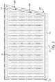
FIG. 4 is a diagram of an embodiment of a route through the field ofFIG. 3 that enables processing of rows at edges of the field; -
FIG. 5 is a diagram of an embodiment of a field having a remaining partial row after being traversed by an implement without overlap subsequent passes of the implement; -
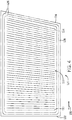
FIG. 6 is a diagram of the field ofFIG. 5 which has been traversed by an implement along an embodiment of a route that causes the implement to overlap passes to eliminate the partial row ofFIG. 5 ; and -
FIG. 7 is a flow diagram view of an embodiment of a process for controlling an off-road vehicle through a field. -
FIG. 1 is a schematic diagram of an embodiment of an off-road vehicle 10 and an agricultural implement 12 within anagricultural field 14. The off-road vehicle 10 (e.g., tractor or other prime mover) is configured to tow the agricultural implement 12 throughout thefield 14 along a direction oftravel 16. The off-road vehicle 10 is directed (e.g., via an operator or an automated system) to traverse the field along substantiallyparallel rows 18. However, it should be appreciated that the off-road vehicle may be directed to traverse the field along other routes in alternative embodiments. For example, at least a portion of the paths may follow a contour located at one edge of thefield 14 that is iteratively phased out or in to form a path that follows line or contour located at an opposite edge of the field. - As will be appreciated, the agricultural implement 12 may be any suitable implement for performing agricultural operations throughout the
field 14. For example, in certain embodiments, the agricultural implement 12 may be a tillage tool, a fertilizer application tool, a seeding or planting tool, a cutting tool, or a harvesting tool, among others. While the agricultural implement 12 is towed and/or pushed by the off-road vehicle 10 in the illustrated embodiment, it should be appreciated that in alternative embodiments, the agricultural implement may be integrated within the off-road vehicle 10. - Furthermore, the
field 14 may have a width that is not an integer multiple of a swath width of the implement 12. In other words, if thefield 14 is traversed usingparallel rows 18 having a width equal to a width of operation of the implement, a final partial row is formed that is only a portion of the width of theother rows 18. Such partial rows may be impractical to traverse without causing undesirable effects to other portions of thefield 14. For example, if the crop being cut is hay, cutting the partial row may be difficult or impossible to complete without cutting into outer windrows of thefield 14. As noted above, recutting the outer windrows may potentially make further processing more difficult by plugging or clogging machinery and/or causing more frequent maintenance that may be costly and significantly time-consuming, thereby reducing the efficiency of field operations. -
FIG. 2 is a schematic diagram of an embodiment of acontrol system 24 that may be utilized to control the off-road vehicle 10 and the agricultural implement ofFIG. 1 . In the illustrated embodiment, thecontrol system 24 includes a vehicle control system 26 (e.g., mounted on the off-road vehicle 10), and the off-road vehicle 10 includes afirst transceiver 28 configured to establish a wireless communication link with asecond transceiver 30 of abase station 32. As will be appreciated, the first and second transceivers may operate at any suitable frequency range within the electromagnetic spectrum. For example, in certain embodiments, the transceivers may broadcast and receive radio waves within a frequency range of about 1 GHz to about 10 GHz. In addition, the first and second transceivers may utilize any suitable communication protocol, such as a standard protocol (e.g., Wi-Fi, Bluetooth, etc.) or a proprietary protocol. - In the illustrated embodiment, the off-
road vehicle 10 includes aspatial locating device 34, which is mounted to the off-road vehicle 10 and configured to determine a position of the off-road vehicle 10. As will be appreciated, the spatial locating device may include any suitable system configured to determine the position of the off-road vehicle, such as a global positioning system (GPS) receiver, for example. In certain embodiments, thespatial locating device 34 may be configured to determine the position of the off-road vehicle relative to a fixed point within the field (e.g., via a fixed radio transceiver). Accordingly, thespatial locating device 34 may be configured to determine the position of the off-road vehicle relative to a fixed global coordinate system (e.g., via the GPS) or a fixed local coordinate system. In certain embodiments, thefirst transceiver 28 is configured to broadcast a signal indicative of the position of the off-road vehicle 10 to thetransceiver 30 of thebase station 32. Using the position of the off-road vehicle 10 during traversal of thefield 14, a map may be made of thefield 14. For example, as the off-road vehicle 10 or another lighter scouting vehicle travels around a portion of thefield 14, thecontrol system 24 and/or thevehicle control system 26 may generate a map of thefield 14. Specifically, in some embodiments, the off-road vehicle 10 or scouting vehicle may be directed to travel around a perimeter of thefield 14 to determine the outer bounds of thefield 14 and then to determine a traversal route. Additionally or alternatively, a map may be updated in during operation of the off-road vehicle 10 to store location of objects that interfere with operation, such as roads, structures, fixtures (e.g., irrigation systems), or other objects that may be fixed within thefield 14. - In addition, the off-
road vehicle 10 includes asensor assembly 36. In certain embodiments, the sensor assembly is configured to facilitate determination of conditions of the off-road vehicle 10 and/or thefield 14. For example, thesensor assembly 36 may include multiple sensors (e.g., infrared sensors, ultrasonic sensors, magnetic sensors, etc.) configured to monitor a rotation rate of a respective wheel or track and/or a land speed of the off-road vehicle. The sensors may also track operating levels (e.g., temperature, fuel level, etc.) of the off-road vehicle 10. Furthermore, the sensors may track conditions in and around the field, such as temperature, weather, wind speed, humidity, objects in the field, and other such conditions. - In the illustrated embodiment, the off-
road vehicle 10 includes asteering control system 38 configured to control a direction of movement of the off-road vehicle 10, and aspeed control system 40 configured to control a speed of the off-road vehicle 10. In addition, the off-road vehicle 10 includes atraction control system 42 configured to control distribution of power from an engine of the off-road vehicle to wheels or tracks of the off-road vehicle, and animplement control system 44 configured to control operation of an implement (e.g., towed by the off-road vehicle 10). Furthermore, thevehicle control system 26 includes acontroller 46 communicatively coupled to thefirst transceiver 28, to thespatial locating device 34, to thesensor assembly 36, to thesteering control system 38, to thespeed control system 40, to thetraction control system 42, and to the implementcontrol system 44. In certain embodiments, thecontroller 46 is configured to receive a location of the off-road vehicle 10 and move the vehicle based at least in part on the location of the off-road vehicle 10 and a route of traversal through thefield 14. - In certain embodiments, the
controller 46 is an electronic controller having electrical circuitry configured to process data from thetransceiver 28, thespatial locating device 34, thesensor assembly 36, or a combination thereof, among other components of the off-road vehicle 10. In the illustrated embodiment, thecontroller 46 includes a processor, such as the illustratedmicroprocessor 48, and amemory device 50. Thecontroller 46 may also include one or more storage devices and/or other suitable components. Theprocessor 48 may be used to execute software, such as software for controlling the off-road vehicle 10, and so forth. Moreover, theprocessor 48 may include multiple microprocessors, one or more "general-purpose" microprocessors, one or more special-purpose microprocessors, and/or one or more application specific integrated circuits (ASICS), or some combination thereof. For example, theprocessor 48 may include one or more reduced instruction set (RISC) processors. - The
memory device 50 may include a volatile memory, such as random access memory (RAM), and/or a nonvolatile memory, such as read-only memory (ROM). Thememory device 50 may store a variety of information and may be used for various purposes. For example, thememory device 50 may store processor-executable instructions (e.g., firmware or software) for theprocessor 48 to execute, such as instructions for controlling the off-road vehicle 10. The storage device(s) (e.g., nonvolatile storage) may include ROM, flash memory, a hard drive, or any other suitable optical, magnetic, or solid-state storage medium, or a combination thereof. The storage device(s) may store data (e.g., field maps), instructions (e.g., software or firmware for controlling the off-road vehicle, etc.), and any other suitable data. - In the illustrated embodiment, the
steering control system 38 includes a wheelangle control system 52, adifferential braking system 54, and atorque vectoring system 56. The wheelangle control system 52 may automatically rotate one or more wheels or tracks of the off-road vehicle (e.g., via hydraulic actuators) to steer the off-road vehicle along a path through the field (e.g., around mapped objects in a field). By way of example, the wheelangle control system 52 may rotate front wheels/tracks, rear wheels/tracks, and/or intermediate wheels/tracks of the off-road vehicle, either individually or in groups. Thedifferential braking system 54 may independently vary the braking force on each lateral side of the off-road vehicle to direct the off-road vehicle along the path through the field. Similarly, thetorque vectoring system 56 may differentially apply torque from the engine to wheels and/or tracks on each lateral side of the off-road vehicle, thereby directing the off-road vehicle along the path through the field. While the illustratedsteering control system 38 includes the wheelangle control system 52, thedifferential braking system 54, and thetorque vectoring system 56, it should be appreciated that alternative embodiments may include one or more of these systems, in any suitable combination. Further embodiments may include asteering control system 38 having other and/or additional systems to facilitate directing the off-road vehicle along the path through the field (e.g., an articulated steering system, etc.). - In the illustrated embodiment, the
speed control system 40 includes an engineoutput control system 58, atransmission control system 60, and abraking control system 62. The engineoutput control system 58 is configured to vary the output of the engine to control the speed of the off-road vehicle 10. For example, the engineoutput control system 58 may vary a throttle setting of the engine, a fuel/air mixture of the engine, a timing of the engine, and/or other suitable engine parameters to control engine output or a combination thereof. In addition, thetransmission control system 60 may adjust an input-output ratio within a transmission to control the speed of the off-road vehicle. Furthermore, thebraking control system 62 may adjust braking force, thereby controlling the speed of the off-road vehicle 10. While the illustratedspeed control system 40 includes the engineoutput control system 58, thetransmission control system 60, and thebraking control system 62, it should be appreciated that alternative embodiments may include one or two of these systems, in any suitable combination. Further embodiments may include aspeed control system 40 having other and/or additional systems to facilitate adjusting the speed of the off-road vehicle. - In the illustrated embodiment, the
traction control system 42 includes a four-wheeldrive control system 64 and a differentiallocking control system 66. The four-wheeldrive control system 64 is configured to selectively engage and disengage a four-wheel drive system of the off-road vehicle. For example, in certain embodiments, the off-road vehicle may include a four wheel drive system configured to direct engine output to the rear wheels/tracks while disengaged, and to direct engine output to the front wheels/tracks and the rear wheels/tracks while engaged. In such embodiments, the four wheeldrive control system 64 may selectively instruct the four wheel drive system to engage and disengage to control traction of the off-road vehicle. In certain embodiments, the off-road vehicle may include intermediate wheels/tracks positioned between the front wheels/tracks and the rear wheels/tracks. In such embodiments, the four-wheel drive control system may also control the transfer of engine power to the intermediate wheels/tracks. - In addition, the differential
locking control system 66 is configured to selectively engage a differential locking system of at least one locking differential between a respective pair of wheels/tracks. For example, in certain embodiments, a locking differential is positioned between the rear wheels/tracks and configured to transfer engine power to the rear wheels/tracks. While the differential locking system is disengaged, the differential is unlocked. As a result, the rotational speed of one rear wheel/track may vary relative to the rotational speed of the other rear wheel/track. However, when the differential locking system is engaged, the differential is locked. As a result, the rotational speeds of the rear wheels/tracks may be substantially equal to one another. In certain embodiments, a locking differential may be positioned between the front wheels/tracks and/or between intermediate wheels/tracks. In certain embodiments, the differentiallocking control system 66 is configured to independently engage and disengage the differential locking system of each locking differential. While the illustratedtraction control system 42 includes the four-wheeldrive control system 64 and the differentiallocking control system 66, it should be appreciated that alternative embodiments may include only one of these systems. Further embodiments may include atraction control system 42 having other and/or additional systems to facilitate control of traction of the off-road vehicle 10. - The implement
control system 44 is configured to control various parameters of the agricultural implement towed by the off-road vehicle. For example, in certain embodiments, the implementcontrol system 44 may be configured to instruct an implement controller (e.g., via a communication link, such as a CAN bus or ISOBUS) to adjust a penetration depth of at least one ground-engaging tool of the agricultural implement. By way of example, the implementcontrol system 44 may instruct the implement controller to reduce the penetration depth of each tillage point on a tilling implement, or the implementcontrol system 44 may instruct the implement controller to disengage each opener disc/blade of a seeding/planting implement from the soil. Reducing the penetration depth of at least one ground-engaging tool of the agricultural implement may reduce the draft load on the off-road vehicle. Furthermore, the implementcontrol system 44 may instruct the implement controller to transition the agricultural implement between a working position and a transport portion, to adjust a flow rate of product from the agricultural implement, or to adjust a position of a header of the agricultural implement (e.g., a harvester, etc.), among other operations. - In certain embodiments, the
vehicle controller 46 may directly control the penetration depth of at least one ground-engaging tool of the agricultural implement. For example, the off-road vehicle controller 46 may instruct a three-point hitch (e.g., via a three-point hitch controller) to raise and lower the agricultural implement or a portion of the agricultural implement relative to the soil surface, thereby adjusting the penetration depth of the at least one ground engaging tool of the agricultural implement. In addition, the off-road vehicle controller 46 may instruct a hydraulic control system to adjust hydraulic fluid pressure and/or flow to one or more actuators on the agricultural implement, thereby controlling the penetration depth of respective ground engaging tool(s). In some embodiments, thevehicle controller 46 may instruct other operating machinery of the implement (e.g., cutting machinery) when to begin and when to stop operation. - As previously discussed, the off-
road vehicle 10 is configured to communicate with thebase station 32 via thetransceivers controller 68 communicatively coupled to thebase station transceiver 30. Thecontroller 68 is configured to output commands and/or data to the off-road vehicle 10. For example, as discussed in detail below, thecontroller 68 may be configured to determine a map of the field and/or a route of thevehicle controller 46 through the field, thereby enabling the vehicle controller to direct the vehicle though thefield 14. In addition, thecontroller 68 may output start and stop commands to thevehicle controller 46, and/or thecontroller 68 may instruct the off-road vehicle to follow a selected/planned path through thefield 14 based on the map and the location of thevehicle 10, which may be determined at thecontroller 46 and/or thecontroller 68. - In certain embodiments, the
controller 68 is an electronic controller having electrical circuitry configured to process data from certain components of the base station 32 (e.g., the transceiver 30). In the illustrated embodiment, thecontroller 68 includes a processor, such as the illustratedmicroprocessor 70, and amemory device 72. Theprocessor 68 may be used to execute software, such as software for providing commands and/or data to the off-road vehicle controller 46, and so forth. Moreover, theprocessor 48 may include multiple microprocessors, one or more "general-purpose" microprocessors, one or more special-purpose microprocessors, and/or one or more application specific integrated circuits (ASICS), or some combination thereof. For example, theprocessor 70 may include one or more reduced instruction set (RISC) processors. Thememory device 72 may include a volatile memory, such as RAM, and/or a nonvolatile memory, such as ROM. Thememory device 72 may store a variety of information and may be used for various purposes. For example, thememory device 72 may store processor-executable instructions (e.g., firmware or software) for theprocessor 70 to execute, such as instructions for providing commands and/or data to the off-road vehicle controller 46. - In the illustrated embodiment, the
base station 32 includes auser interface 74 communicatively coupled to thecontroller 68. Theuser interface 74 is configured to present data from the one or more off-road vehicles and/or the agricultural implements to an operator (e.g., data associated with operation of the off-road vehicle, data associated with operation of the agricultural implement, etc.). Theuser interface 74 may also enable the user to input information about thefield 14 and/or the crops that may alter the route through the field. For example, if the crop is a row crop (e.g., corn), the operator may indicate such information and a width of each swath may be fixed. However, if the crop is a non-row crop (e.g., hay; small grain such as wheat, barley, grass seed, canola, etc.); pulse crops (peas, lentils, etc.), the information may be input and the width of each swath may be used to traverse thefield 14 in a path alternative to the rows that would be used for row crops since non-row crop swaths may be adjusted without interfering with row operations. Theuser interface 74 is also configured to enable an operator to control certain functions of the off-road vehicle (e.g., starting and stopping the off-road vehicle, instructing the off-road vehicle to follow a route through the field, etc.). In the illustrated embodiment, the user interface includes adisplay 76 configured to present information to the operator, such as the position of the off-road vehicle 10 within the field, the speed of the off-road vehicle, and the path of the off-road vehicle, among other data. Thedisplay 76 may include touch inputs and/or the user interface may rely on other input devices, such as a keyboard, mouse, or other human-to-machine input devices. In addition, the user interface 74 (e.g., via thedisplay 76, via an audio system, etc.) is configured to notify the operator of the determined route to be used to traverse thefield 14. Theuser interface 74 may also alert the user of various operating conditions that affect the operation of the off-road vehicle 10. For example, in certain embodiments, theuser interface 74 may alert the operator if the off-road vehicle is experiencing a substantial degree of slippage. - In the illustrated embodiment, the
base station 32 includes astorage device 78 communicatively coupled to thecontroller 68. The storage device 78 (e.g., nonvolatile storage) may include ROM, flash memory, a hard drive, or any other suitable optical, magnetic, or solid-state storage medium, or a combination thereof. The storage device(s) may store data (e.g., field maps), instructions (e.g., software or firmware for commanding the off-road vehicle, etc.), and any other suitable data. - While the
vehicle control system 26 of thecontrol system 24 includes the off-road vehicle controller 46 in the illustrated embodiment, it should be appreciated that in alternative embodiments, thevehicle control system 26 may include thebase station controller 68. For example, in certain embodiments, control functions of thevehicle control system 26 may be distributed between the off-road vehicle controller 46 and thebase station controller 68. In further embodiments, thebase station controller 68 may perform a substantial portion of the control functions of thevehicle control system 26. Indeed, any processes of thecontrollers - With the foregoing in mind, as the off-
road vehicle 10 and the agricultural implement 12 traverse the field, the off-road vehicle 10 and the agricultural implement 12 may encounter various field shapes that are non-rectangular and/or have widths unequal to a an integer multiple of a width of a single pass of thevehicle 10. For example,FIG. 3 is a diagram of afield 120 having a trapezoidal shape with asquared edge 122 and anon-squared edge 124. If thefield 120 is traversed along substantiallyparallel rows 18, traversing a field with a non-squared corner 126 o may be relatively difficult or impossible without engagingouter windrows 128. Specifically,rows 18 that terminate at an angle with theedge 124 of thefield 120 may cause engaging (e.g., cutting) and/or reengaging portions that are not to be reengaged (e.g., windrows). Although the illustratedfield 120 includes a trapezoidal shape, some embodiments may have any shape that has a sharp or acute angle in one or more corners and/or includes one or more contours on at least one side of thefield 120 causing therows 18 to terminate at a windrow at a substantially non-perpendicular angle. - Instead of merely engaging swaths of a maximum width, a pre-planned route, as illustrated in
FIG. 4 and discussed below, may be created that follows a first contour of theedge 122 near theedge 122 and follows a second contour of theopposite edge 124 near theedge 124 with atransition zone 130 that transitions from the first contour to the second contour as consecutive passes are performed, each pass increasing distant from theedge 122 along ahorizontal direction 132 in thefield 120. For example, afirst row 133 may have the first contour while asecond row 134 may have the second contour, and all rows in between therow 133 and therow 134 may have a contour that is a combination of the first and second contours to a contour that is between the first and second contours. Such transitions may cause some overlap of the passes of the implement 12, but the inefficiency of traveling over previously traversed portions of thefield 120 is offset by enabling processing of thefield 120 due to thenon-squared corner 126. As discussed previously, the contours may be tracked by traveling at least a portion (e.g., a perimeter) of thefield 120 with the off-road vehicle 10 to map thefield 120 to determine the pre-planned route using location information (e.g., derived using GPS data) during a mapping process for thefield 120. - Also, as noted above, partial rows (e.g., rows that are less than a full swath width) may be impossible or impractical to process (e.g., cut) without also processing other portions of the
field 14 that have already been processed. For example,FIG. 5 is a diagram of an embodiment of afield 150 that has awidth 152 to be processed in rows that is not an integer multiple of aswath width 154, in which theswath width 154 is the width of a single pass of the implement 12 through thefield 150. For example, if the implement 12 is a hay-cutting implement, theswath width 154 is the width of hay cut in a single pass of the implement 12 in thefield 150. As illustrated, a cutting route uses theswath width 154 to define row width. In other words, in the cutting route illustrated in thefield 150, minimal to no overlap exists between adjacent rows. If the width of thefield 150 is an integer multiple of theswath width 154 such a method may be the most efficient. Moreover, if the crop type is a row crop (e.g., corn), the rows may be spaced equally due to fixed-width implements that plant the rows in specific positions in relation to each other. However, if the crop is a non-row crop (e.g., hay) and thefield 150 has a width (e.g., width 152) that is not an integer multiple of theswath width 154, a partial row may not be processed (e.g., cut) properly without potentially causing processing of portions that are not to be processed (e.g., windrows). Furthermore, although the illustrated embodiment of thefield 150 includes elevenfull rows 156 each having aswath width 154 and onepartial row 158, it should be noted that the processes discussed herein are applicable to any field that has awidth 152 that is not an integer multiple of aswath width 154 of the implement 12. As previously noted, thepartial row 158 may be difficult to process without effecting portions 160 (e.g., windrows) that would not need to be processed a second time. -
FIG. 6 is a diagram of an embodiment of apre-planned route 170 that may be used to process crops in thefield 150. Specifically, thepre-planned route 170 enables processing of material corresponding to thepartial row 158 ofFIG. 5 . The illustrated embodiment of thepre-planned route 170 includes twelve overlappingrows 162 that overlap with adjacent rows in anoverlap region 164 having an overlap width 166. In some embodiments, the overlap width 166 may be calculated using the following equation:
overlap regions 164, WPR is the width of the partial row that would remain if cut using theswath width 154 as the width of the rows, and n is the number of full rows that would be cut if usingswath width 154 as the width of the rows. In turn, WPR may be calculated using the following equation:
partial row 158 is redistributed among the rows such that the overlaps sum up to the partial row enabling processing of the entire field without risking additional processing to portions not to be processed. If WPR is equal to zero, the width of the portion of the field to be processed is an integer multiple of the swath width of the implement 12. -
FIG. 7 is a flow diagram of aprocess 200 for operating the off-road vehicle 10 and the implement 12. Theprocess 200 may be at least performed by thecontroller 46, thecontroller 68, a remote processor (e.g., cloud service), or some combination thereof. A route for a field may default to a default route, such as parallel rows having a width equal to a swath width of the implement 12 (block 202). Theprocess 200 includes obtaining information about thefield 14, 150 (block 204). For example, thedisplay 76 may present instructions, e.g., as part of an initialization process for the field, for an operator to circumnavigate a perimeter or traverse an area of thefield spatial locating device 34 determines a location for the off-road vehicle 10 during the initialization process. Thecontrollers 46 and/or 68 track the location of the off-road vehicle 10 using this information. Using the location information, a map is made of the field (block 206). The map may include a two-dimensional boundary of the field, a two-dimensional graph of the locations of the off-road vehicle 10, a three-dimensional graph of the terrain, or a combination thereof. - The map may be used to determine a different route of travel based on various factors of the field. For example, if the field has contours that are different on opposing sides, and/or a width of the field to be processed is not an integer multiple of the swath width of the implement, the pre-planned route through the field may be determined (e.g., the defailt path may be modified). In analyzing the map, a determination is made whether the field includes any sharp corners (block 208). For example, a determination is made whether the field includes contours that would cause one or more rows to terminate at an edge of the field at an angle that is substantially non-perpindicular (e.g., acute or obtuse) to set an appropriate route to be traveled through the field. As noted above, such angles may cause the one or more rows to be difficult or impossible to process without processing undesired portions (e.g., windrows).
- If the field includes any sharp corners or contours, the pre-planned route is established to follow a first contour at a first edge of the field (block 210). The pre-planned route is also determined to phase out or in the contour of the first edge while oppositely phasing in or out a second contour of a second edge opposing the first edge (block 212), through each subsequent pass/row. For example, the first contour may be a straight line along the first edge, and the second contour may be a line angling away from or toward the first edge. In other words, the second edge is not parallel to the first edge. In such a change in angle from the first contour to the second contour, in some embodiments, the angle for a specific row may be determined as the angle of intersection between the first and second edges if the edges were extended scaled by a lateral distance from the first edge divided by the total width of the field and modifying the angle of the first edge by calculated quotient. In other words, the angle between the first and second edge may be distributed equally throughout the rows in the field.
- The map is also analyzed to determine whether a partial row exists. Specifically, the map may be analyzed to determine whether the width of the field to be processed is an integer mulitple of the swath width of the implement (block 214). For example, if the swath width of the implement is twenty-four feet, integer multiples of the swath width would be 48, 72, 96, 120, 144, 168, 192 feet (1 foot= 0,3048 m), and so on. Any other widths of the field may result in a partial row. If a partial row would exist, the pre-planned route may be determined such that each row/pass of the implement overlaps an adjacent row/pass (block 216). In other words, the overlaps distribute the width of a partial row into overlap areas to enable the entire field to processed (e.g., cut) without processing additional areas that are not to be processed (e.g., existing windrows). Once the pre-planned route has been determined, the pre-planned route is used to control the implement (block 218). For example, the tractor may be controlled to direct the implement along the route. In some embodiments, the map may also be used to determine when machinery (e.g., cutting machinery) of the implement is to begin operation (e.g., when the off-
road vehicle 10 and/or the implement 12 has entered into the area of the field to be processed) or stop operation (e.g., when the off-road vehicle 10 and/or the implement 12 has exited the area of the field to be processed). - While only certain features of the disclosure have been illustrated and described herein, many modifications and changes will occur to those skilled in the art, within the scope of the appended claims.
Claims (10)
- A control system (24) for an off-road vehicle (10), comprising:memory (50, 72) storing instructions;a processor (48, 70) configured to execute the instructions to cause the processor (48, 70) to:determine whether a first contour of a first edge (124) of a field (14, 120, 150) differs from a second contour of a second edge (122) of the field (14, 120, 150) that is on an opposite side of the field from the first edge; andif the first contour differs from the second contour, determine a pre-planned route of travel through the field for the off-road vehicle (10), wherein the pre-planned route includes:a first pass of the off-road vehicle (10) that follows the first contour at the first edge (124);subsequent passes of the off-road vehicle (10) to incrementally shift from the first contour to the second contour using partial overlaps (164) of passes of an implement towed by or integrated into the off-road vehicle (10); anda final pass of the off-road vehicle (10) that follows the second contour at the second edge;characterized in that the instructions are further configured to cause the processor (48, 70) to:determine whether a row, defined as partial row (158), that is less than a full swath width (154) would exist using the pre-planned route, wherein said swath width (154) is the width of a single pass of the implement (12) through the field (150); andif said partial row (158) would exist, adjust the determined pre-planned route to eliminate said partial row (158) by dividing the width of the partial row (158) between said overlap areas (164) of each pass (162) of the implement and control the off-road vehicle (10) to traverse the field (12) along substantially parallel rows (18) based at least in part on the pre-planned route.
- The control system (24) of claim 1, wherein the first contour is different from the second contour when an acute angle is formed in a corner (126) of the field (14, 120, 150) between the first edge (124) of the field (14, 120, 150) and an adjacent edge of the field (14, 120, 150).
- The control system (24) of claim 1, comprising a user interface (74) that provides information and receives selections.
- The control system (24) of claim 3, wherein the user interface (74) is configured to receive a selection of a crop type.
- The control system (24) of claim 4, wherein the determination of contour differences is used only when a non-row crop type is selected.
- The control system (24) of claim 1, wherein the incremental shift from the first contour to the second contour for each pass is a function of a distance of the pass from the first edge (124).
- The control system (24) of any of one of the above claims, comprising:the off-road vehicle (10); anda base station (32), wherein the processor (48, 70) is located in the off-road vehicle (10), in the base station (32), or distributed between both the base station and the off-road vehicle (10).
- The control system (24) of claims 1, wherein the adjustment to eliminate the partial row (158) using the overlap areas (164) is used when a selection indicates a non-row crop.
- The control system (24) of claim 8, wherein a width of the overlap areas (164) for each row is calculated using the following equation:


- The control system (24) of claim 1, comprising a spatial locating device (34) that indicates a location of the off-road vehicle (10) that is configured to enable mapping the field (14, 120, 150) for generation and adjustment of the pre-planned route.
Applications Claiming Priority (2)
| Application Number | Priority Date | Filing Date | Title |
|---|---|---|---|
| US15/179,597 US10073457B2 (en) | 2016-06-10 | 2016-06-10 | Autoscaling rows of travel for an off-road vehicle |
| PCT/US2017/036615 WO2017214438A1 (en) | 2016-06-10 | 2017-06-08 | Autoscaling rows of travel for an off-road vehicle |
Publications (2)
| Publication Number | Publication Date |
|---|---|
| EP3468334A1 EP3468334A1 (en) | 2019-04-17 |
| EP3468334B1 true EP3468334B1 (en) | 2021-03-17 |
Family
ID=59078233
Family Applications (1)
| Application Number | Title | Priority Date | Filing Date |
|---|---|---|---|
| EP17731408.5A Active EP3468334B1 (en) | 2016-06-10 | 2017-06-08 | Autoscaling rows of travel for an off-road vehicle |
Country Status (7)
| Country | Link |
|---|---|
| US (1) | US10073457B2 (en) |
| EP (1) | EP3468334B1 (en) |
| CN (1) | CN109310044A (en) |
| AU (2) | AU2017277801B2 (en) |
| BR (1) | BR112018075507B1 (en) |
| RU (1) | RU2721576C1 (en) |
| WO (1) | WO2017214438A1 (en) |
Families Citing this family (10)
| Publication number | Priority date | Publication date | Assignee | Title |
|---|---|---|---|---|
| JP7034860B2 (en) * | 2018-08-03 | 2022-03-14 | ヤンマーパワーテクノロジー株式会社 | Area registration system |
| JP7237788B2 (en) * | 2019-09-26 | 2023-03-13 | 株式会社クボタ | work vehicle |
| JP7275013B2 (en) * | 2019-11-29 | 2023-05-17 | 株式会社クボタ | automatic driving system |
| US12016257B2 (en) | 2020-02-19 | 2024-06-25 | Sabanto, Inc. | Methods for detecting and clearing debris from planter gauge wheels, closing wheels and seed tubes |
| JP7332502B2 (en) * | 2020-02-27 | 2023-08-23 | 三菱マヒンドラ農機株式会社 | Route creation management system |
| US12461083B2 (en) | 2020-08-03 | 2025-11-04 | Sabanto, Inc. | Methods for improved agricultural procedures |
| CN112703834B (en) * | 2020-12-03 | 2022-08-16 | 广州极飞科技股份有限公司 | Sweeping path planning method, land block leveling operation path determining method and device |
| EP4342273A4 (en) * | 2021-05-18 | 2024-11-27 | Kubota Corporation | AGRICULTURAL WORK ASSISTANCE SYSTEM, AGRICULTURAL WORK ASSISTANCE DEVICE AND AGRICULTURAL MACHINE |
| US12532794B2 (en) | 2022-12-27 | 2026-01-27 | Cnh Industrial Canada, Ltd. | System and method for controlling an agricultural system based on slip |
| IT202300007881A1 (en) * | 2023-04-21 | 2024-10-21 | Cnh Ind Italia Spa | WORK VEHICLE AND RELATED CONTROL METHOD |
Family Cites Families (26)
| Publication number | Priority date | Publication date | Assignee | Title |
|---|---|---|---|---|
| AU547146B2 (en) | 1982-07-13 | 1985-10-10 | Kubota Ltd. | Automatic running work vehicle |
| JPS5911409A (en) * | 1982-07-13 | 1984-01-21 | Kubota Ltd | Unmanned traveling truck |
| DK166424C (en) | 1987-06-04 | 1993-05-24 | Freudendahl J Fab As | CUTTERS WITH FIXED ASYMMETRY FOR HARVESTING CEREALS |
| DE19508562A1 (en) * | 1995-03-10 | 1996-09-12 | Amazonen Werke Dreyer H | Device for creating tramlines with a seeder |
| US6055799A (en) | 1995-10-04 | 2000-05-02 | Universite Laval & Agriculture Et Agro-Alimentaire Canada | Forage conditioning machine |
| US6236924B1 (en) * | 1999-06-21 | 2001-05-22 | Caterpillar Inc. | System and method for planning the operations of an agricultural machine in a field |
| US8265826B2 (en) | 2003-03-20 | 2012-09-11 | Hemisphere GPS, LLC | Combined GNSS gyroscope control system and method |
| US8634993B2 (en) * | 2003-03-20 | 2014-01-21 | Agjunction Llc | GNSS based control for dispensing material from vehicle |
| US7216033B2 (en) | 2003-03-31 | 2007-05-08 | Deere & Company | Path planner and method for planning a contour path of a vehicle |
| US6907336B2 (en) * | 2003-03-31 | 2005-06-14 | Deere & Company | Method and system for efficiently traversing an area with a work vehicle |
| DE102004027242A1 (en) * | 2004-06-03 | 2005-12-22 | Claas Selbstfahrende Erntemaschinen Gmbh | Route planning system for agricultural machines |
| US7715979B2 (en) | 2006-10-27 | 2010-05-11 | Cnh America Llc | Nudge compensation for curved swath paths |
| US7715966B2 (en) | 2007-03-02 | 2010-05-11 | Cnh America Llc | Method for creating spiral swath patterns for convex polygon shaped field boundaries |
| US8060269B2 (en) | 2008-04-16 | 2011-11-15 | Cnh America Llc | Swath line creation including slope compensation for an automatic guidance system of a work vehicle |
| CA2730372A1 (en) * | 2008-09-19 | 2010-03-25 | Better Place GmbH | System and method for operating an electric vehicle |
| US8296052B2 (en) | 2009-04-08 | 2012-10-23 | Cnh America Llc | Method for avoiding point rows for quadrilateral fields using autoguidance |
| US8655536B2 (en) * | 2009-11-16 | 2014-02-18 | Trimble Navigation Limited | Method and system for augmenting a guidance system with a path sensor |
| US8498788B2 (en) * | 2010-10-26 | 2013-07-30 | Deere & Company | Method and system for determining a planned path of a vehicle |
| JP2013228821A (en) | 2012-04-24 | 2013-11-07 | Mamiya-Op Nequos Co Ltd | Working machine, component device thereof, and computer program |
| US9123113B2 (en) | 2013-03-08 | 2015-09-01 | Raven Industries, Inc. | Row guidance parameterization with Hough transform |
| RU2550915C1 (en) * | 2013-11-19 | 2015-05-20 | Юрий Феликсович Черняков | Precise run tractor and method of automatic control over local reference points |
| BR102014027008B1 (en) * | 2013-12-11 | 2020-07-21 | Cnh Industrial America Llc. | agricultural vehicle and related method |
| CN203775639U (en) * | 2014-04-04 | 2014-08-20 | 合肥多加农业科技有限公司 | Device for automatically adjusting and controlling walking direction of agricultural implement |
| DE112015002194T5 (en) | 2014-05-09 | 2017-01-19 | Raven Industries, Inc. | Improved serialization parameterization with Hough transformation |
| CN105340431A (en) * | 2015-12-11 | 2016-02-24 | 淄博大创自动化科技有限公司 | Agricultural seeder provided with guide sowing wheel |
| US10073460B2 (en) * | 2016-06-10 | 2018-09-11 | Trimble Inc. | Providing auto-guidance of a mobile machine without requiring a graphical interface display |
-
2016
- 2016-06-10 US US15/179,597 patent/US10073457B2/en active Active
-
2017
- 2017-06-08 WO PCT/US2017/036615 patent/WO2017214438A1/en not_active Ceased
- 2017-06-08 EP EP17731408.5A patent/EP3468334B1/en active Active
- 2017-06-08 CN CN201780035784.3A patent/CN109310044A/en active Pending
- 2017-06-08 RU RU2019100026A patent/RU2721576C1/en active
- 2017-06-08 BR BR112018075507-9A patent/BR112018075507B1/en active IP Right Grant
- 2017-06-08 AU AU2017277801A patent/AU2017277801B2/en active Active
-
2023
- 2023-06-14 AU AU2023203706A patent/AU2023203706A1/en not_active Abandoned
Non-Patent Citations (1)
| Title |
|---|
| None * |
Also Published As
| Publication number | Publication date |
|---|---|
| BR112018075507B1 (en) | 2022-05-10 |
| AU2017277801A1 (en) | 2018-12-13 |
| AU2017277801B2 (en) | 2023-03-23 |
| AU2023203706A1 (en) | 2023-07-06 |
| US20170357261A1 (en) | 2017-12-14 |
| RU2721576C1 (en) | 2020-05-20 |
| EP3468334A1 (en) | 2019-04-17 |
| WO2017214438A1 (en) | 2017-12-14 |
| CN109310044A (en) | 2019-02-05 |
| US10073457B2 (en) | 2018-09-11 |
| BR112018075507A2 (en) | 2019-03-19 |
Similar Documents
| Publication | Publication Date | Title |
|---|---|---|
| AU2017277801B2 (en) | Autoscaling rows of travel for an off-road vehicle | |
| US10459447B2 (en) | System and method for generating partitioned swaths | |
| US10492355B2 (en) | Path planning system for a work vehicle | |
| US10583832B2 (en) | Obstacle detection system for a work vehicle | |
| US11235772B2 (en) | Slip control system for an off-road vehicle | |
| CN109152332B (en) | Planning and control of autonomous agricultural operations | |
| EP2116121B1 (en) | Swath line creation including slope compensation for an automatic guidance system of a work vehicle | |
| EP3254548B1 (en) | Planning and control of autonomous agricultural operations | |
| US10729055B2 (en) | System and method for determining swath connections | |
| US10390474B2 (en) | Path planning system for a work vehicle | |
| US10479354B2 (en) | Obstacle detection system for a work vehicle | |
| US10595455B2 (en) | Planning system for an autonomous work vehicle system | |
| EP2238819B2 (en) | Method for avoiding point rows for quadrilateral fields using autoguidance | |
| JP2017131199A (en) | Afforestation system, afforestation method, farming machine, planting machine and management device | |
| US20230085713A1 (en) | Planning system for an autonomous work vehicle system | |
| EP3522695B1 (en) | Slip control system for an off-road vehicle | |
| EP3837956B1 (en) | Mower combination | |
| US20230086887A1 (en) | Planning system for an autonomous work vehicle system |
Legal Events
| Date | Code | Title | Description |
|---|---|---|---|
| STAA | Information on the status of an ep patent application or granted ep patent |
Free format text: STATUS: UNKNOWN |
|
| STAA | Information on the status of an ep patent application or granted ep patent |
Free format text: STATUS: THE INTERNATIONAL PUBLICATION HAS BEEN MADE |
|
| PUAI | Public reference made under article 153(3) epc to a published international application that has entered the european phase |
Free format text: ORIGINAL CODE: 0009012 |
|
| STAA | Information on the status of an ep patent application or granted ep patent |
Free format text: STATUS: REQUEST FOR EXAMINATION WAS MADE |
|
| 17P | Request for examination filed |
Effective date: 20190110 |
|
| AK | Designated contracting states |
Kind code of ref document: A1 Designated state(s): AL AT BE BG CH CY CZ DE DK EE ES FI FR GB GR HR HU IE IS IT LI LT LU LV MC MK MT NL NO PL PT RO RS SE SI SK SM TR |
|
| AX | Request for extension of the european patent |
Extension state: BA ME |
|
| RAP1 | Party data changed (applicant data changed or rights of an application transferred) |
Owner name: CNH INDUSTRIAL ITALIA S.P.A. Owner name: AUTONOMOUS SOLUTIONS, INC. |
|
| DAV | Request for validation of the european patent (deleted) | ||
| DAX | Request for extension of the european patent (deleted) | ||
| STAA | Information on the status of an ep patent application or granted ep patent |
Free format text: STATUS: EXAMINATION IS IN PROGRESS |
|
| 17Q | First examination report despatched |
Effective date: 20200422 |
|
| GRAP | Despatch of communication of intention to grant a patent |
Free format text: ORIGINAL CODE: EPIDOSNIGR1 |
|
| STAA | Information on the status of an ep patent application or granted ep patent |
Free format text: STATUS: GRANT OF PATENT IS INTENDED |
|
| INTG | Intention to grant announced |
Effective date: 20201111 |
|
| GRAS | Grant fee paid |
Free format text: ORIGINAL CODE: EPIDOSNIGR3 |
|
| GRAA | (expected) grant |
Free format text: ORIGINAL CODE: 0009210 |
|
| STAA | Information on the status of an ep patent application or granted ep patent |
Free format text: STATUS: THE PATENT HAS BEEN GRANTED |
|
| AK | Designated contracting states |
Kind code of ref document: B1 Designated state(s): AL AT BE BG CH CY CZ DE DK EE ES FI FR GB GR HR HU IE IS IT LI LT LU LV MC MK MT NL NO PL PT RO RS SE SI SK SM TR |
|
| REG | Reference to a national code |
Ref country code: GB Ref legal event code: FG4D |
|
| REG | Reference to a national code |
Ref country code: CH Ref legal event code: EP |
|
| REG | Reference to a national code |
Ref country code: DE Ref legal event code: R096 Ref document number: 602017034761 Country of ref document: DE |
|
| REG | Reference to a national code |
Ref country code: IE Ref legal event code: FG4D |
|
| REG | Reference to a national code |
Ref country code: AT Ref legal event code: REF Ref document number: 1371309 Country of ref document: AT Kind code of ref document: T Effective date: 20210415 |
|
| REG | Reference to a national code |
Ref country code: LT Ref legal event code: MG9D |
|
| PG25 | Lapsed in a contracting state [announced via postgrant information from national office to epo] |
Ref country code: FI Free format text: LAPSE BECAUSE OF FAILURE TO SUBMIT A TRANSLATION OF THE DESCRIPTION OR TO PAY THE FEE WITHIN THE PRESCRIBED TIME-LIMIT Effective date: 20210317 Ref country code: GR Free format text: LAPSE BECAUSE OF FAILURE TO SUBMIT A TRANSLATION OF THE DESCRIPTION OR TO PAY THE FEE WITHIN THE PRESCRIBED TIME-LIMIT Effective date: 20210618 Ref country code: HR Free format text: LAPSE BECAUSE OF FAILURE TO SUBMIT A TRANSLATION OF THE DESCRIPTION OR TO PAY THE FEE WITHIN THE PRESCRIBED TIME-LIMIT Effective date: 20210317 Ref country code: NO Free format text: LAPSE BECAUSE OF FAILURE TO SUBMIT A TRANSLATION OF THE DESCRIPTION OR TO PAY THE FEE WITHIN THE PRESCRIBED TIME-LIMIT Effective date: 20210617 Ref country code: BG Free format text: LAPSE BECAUSE OF FAILURE TO SUBMIT A TRANSLATION OF THE DESCRIPTION OR TO PAY THE FEE WITHIN THE PRESCRIBED TIME-LIMIT Effective date: 20210617 |
|
| REG | Reference to a national code |
Ref country code: AT Ref legal event code: MK05 Ref document number: 1371309 Country of ref document: AT Kind code of ref document: T Effective date: 20210317 |
|
| REG | Reference to a national code |
Ref country code: NL Ref legal event code: MP Effective date: 20210317 |
|
| PG25 | Lapsed in a contracting state [announced via postgrant information from national office to epo] |
Ref country code: RS Free format text: LAPSE BECAUSE OF FAILURE TO SUBMIT A TRANSLATION OF THE DESCRIPTION OR TO PAY THE FEE WITHIN THE PRESCRIBED TIME-LIMIT Effective date: 20210317 Ref country code: LV Free format text: LAPSE BECAUSE OF FAILURE TO SUBMIT A TRANSLATION OF THE DESCRIPTION OR TO PAY THE FEE WITHIN THE PRESCRIBED TIME-LIMIT Effective date: 20210317 Ref country code: SE Free format text: LAPSE BECAUSE OF FAILURE TO SUBMIT A TRANSLATION OF THE DESCRIPTION OR TO PAY THE FEE WITHIN THE PRESCRIBED TIME-LIMIT Effective date: 20210317 |
|
| PG25 | Lapsed in a contracting state [announced via postgrant information from national office to epo] |
Ref country code: NL Free format text: LAPSE BECAUSE OF FAILURE TO SUBMIT A TRANSLATION OF THE DESCRIPTION OR TO PAY THE FEE WITHIN THE PRESCRIBED TIME-LIMIT Effective date: 20210317 |
|
| PG25 | Lapsed in a contracting state [announced via postgrant information from national office to epo] |
Ref country code: CZ Free format text: LAPSE BECAUSE OF FAILURE TO SUBMIT A TRANSLATION OF THE DESCRIPTION OR TO PAY THE FEE WITHIN THE PRESCRIBED TIME-LIMIT Effective date: 20210317 Ref country code: EE Free format text: LAPSE BECAUSE OF FAILURE TO SUBMIT A TRANSLATION OF THE DESCRIPTION OR TO PAY THE FEE WITHIN THE PRESCRIBED TIME-LIMIT Effective date: 20210317 Ref country code: LT Free format text: LAPSE BECAUSE OF FAILURE TO SUBMIT A TRANSLATION OF THE DESCRIPTION OR TO PAY THE FEE WITHIN THE PRESCRIBED TIME-LIMIT Effective date: 20210317 Ref country code: AT Free format text: LAPSE BECAUSE OF FAILURE TO SUBMIT A TRANSLATION OF THE DESCRIPTION OR TO PAY THE FEE WITHIN THE PRESCRIBED TIME-LIMIT Effective date: 20210317 Ref country code: SM Free format text: LAPSE BECAUSE OF FAILURE TO SUBMIT A TRANSLATION OF THE DESCRIPTION OR TO PAY THE FEE WITHIN THE PRESCRIBED TIME-LIMIT Effective date: 20210317 |
|
| PG25 | Lapsed in a contracting state [announced via postgrant information from national office to epo] |
Ref country code: PT Free format text: LAPSE BECAUSE OF FAILURE TO SUBMIT A TRANSLATION OF THE DESCRIPTION OR TO PAY THE FEE WITHIN THE PRESCRIBED TIME-LIMIT Effective date: 20210719 Ref country code: PL Free format text: LAPSE BECAUSE OF FAILURE TO SUBMIT A TRANSLATION OF THE DESCRIPTION OR TO PAY THE FEE WITHIN THE PRESCRIBED TIME-LIMIT Effective date: 20210317 Ref country code: RO Free format text: LAPSE BECAUSE OF FAILURE TO SUBMIT A TRANSLATION OF THE DESCRIPTION OR TO PAY THE FEE WITHIN THE PRESCRIBED TIME-LIMIT Effective date: 20210317 Ref country code: SK Free format text: LAPSE BECAUSE OF FAILURE TO SUBMIT A TRANSLATION OF THE DESCRIPTION OR TO PAY THE FEE WITHIN THE PRESCRIBED TIME-LIMIT Effective date: 20210317 Ref country code: IS Free format text: LAPSE BECAUSE OF FAILURE TO SUBMIT A TRANSLATION OF THE DESCRIPTION OR TO PAY THE FEE WITHIN THE PRESCRIBED TIME-LIMIT Effective date: 20210717 |
|
| REG | Reference to a national code |
Ref country code: DE Ref legal event code: R097 Ref document number: 602017034761 Country of ref document: DE |
|
| PLBE | No opposition filed within time limit |
Free format text: ORIGINAL CODE: 0009261 |
|
| STAA | Information on the status of an ep patent application or granted ep patent |
Free format text: STATUS: NO OPPOSITION FILED WITHIN TIME LIMIT |
|
| PG25 | Lapsed in a contracting state [announced via postgrant information from national office to epo] |
Ref country code: MC Free format text: LAPSE BECAUSE OF FAILURE TO SUBMIT A TRANSLATION OF THE DESCRIPTION OR TO PAY THE FEE WITHIN THE PRESCRIBED TIME-LIMIT Effective date: 20210317 Ref country code: DK Free format text: LAPSE BECAUSE OF FAILURE TO SUBMIT A TRANSLATION OF THE DESCRIPTION OR TO PAY THE FEE WITHIN THE PRESCRIBED TIME-LIMIT Effective date: 20210317 Ref country code: AL Free format text: LAPSE BECAUSE OF FAILURE TO SUBMIT A TRANSLATION OF THE DESCRIPTION OR TO PAY THE FEE WITHIN THE PRESCRIBED TIME-LIMIT Effective date: 20210317 Ref country code: ES Free format text: LAPSE BECAUSE OF FAILURE TO SUBMIT A TRANSLATION OF THE DESCRIPTION OR TO PAY THE FEE WITHIN THE PRESCRIBED TIME-LIMIT Effective date: 20210317 |
|
| REG | Reference to a national code |
Ref country code: CH Ref legal event code: PL |
|
| 26N | No opposition filed |
Effective date: 20211220 |
|
| PG25 | Lapsed in a contracting state [announced via postgrant information from national office to epo] |
Ref country code: SI Free format text: LAPSE BECAUSE OF FAILURE TO SUBMIT A TRANSLATION OF THE DESCRIPTION OR TO PAY THE FEE WITHIN THE PRESCRIBED TIME-LIMIT Effective date: 20210317 |
|
| REG | Reference to a national code |
Ref country code: BE Ref legal event code: MM Effective date: 20210630 |
|
| PG25 | Lapsed in a contracting state [announced via postgrant information from national office to epo] |
Ref country code: LU Free format text: LAPSE BECAUSE OF NON-PAYMENT OF DUE FEES Effective date: 20210608 |
|
| PG25 | Lapsed in a contracting state [announced via postgrant information from national office to epo] |
Ref country code: LI Free format text: LAPSE BECAUSE OF NON-PAYMENT OF DUE FEES Effective date: 20210630 Ref country code: IE Free format text: LAPSE BECAUSE OF NON-PAYMENT OF DUE FEES Effective date: 20210608 Ref country code: CH Free format text: LAPSE BECAUSE OF NON-PAYMENT OF DUE FEES Effective date: 20210630 |
|
| PG25 | Lapsed in a contracting state [announced via postgrant information from national office to epo] |
Ref country code: IS Free format text: LAPSE BECAUSE OF FAILURE TO SUBMIT A TRANSLATION OF THE DESCRIPTION OR TO PAY THE FEE WITHIN THE PRESCRIBED TIME-LIMIT Effective date: 20210717 |
|
| PG25 | Lapsed in a contracting state [announced via postgrant information from national office to epo] |
Ref country code: BE Free format text: LAPSE BECAUSE OF NON-PAYMENT OF DUE FEES Effective date: 20210630 |
|
| PG25 | Lapsed in a contracting state [announced via postgrant information from national office to epo] |
Ref country code: CY Free format text: LAPSE BECAUSE OF FAILURE TO SUBMIT A TRANSLATION OF THE DESCRIPTION OR TO PAY THE FEE WITHIN THE PRESCRIBED TIME-LIMIT Effective date: 20210317 |
|
| PG25 | Lapsed in a contracting state [announced via postgrant information from national office to epo] |
Ref country code: HU Free format text: LAPSE BECAUSE OF FAILURE TO SUBMIT A TRANSLATION OF THE DESCRIPTION OR TO PAY THE FEE WITHIN THE PRESCRIBED TIME-LIMIT; INVALID AB INITIO Effective date: 20170608 |
|
| PG25 | Lapsed in a contracting state [announced via postgrant information from national office to epo] |
Ref country code: MK Free format text: LAPSE BECAUSE OF FAILURE TO SUBMIT A TRANSLATION OF THE DESCRIPTION OR TO PAY THE FEE WITHIN THE PRESCRIBED TIME-LIMIT Effective date: 20210317 |
|
| PG25 | Lapsed in a contracting state [announced via postgrant information from national office to epo] |
Ref country code: TR Free format text: LAPSE BECAUSE OF FAILURE TO SUBMIT A TRANSLATION OF THE DESCRIPTION OR TO PAY THE FEE WITHIN THE PRESCRIBED TIME-LIMIT Effective date: 20210317 |
|
| PG25 | Lapsed in a contracting state [announced via postgrant information from national office to epo] |
Ref country code: MT Free format text: LAPSE BECAUSE OF FAILURE TO SUBMIT A TRANSLATION OF THE DESCRIPTION OR TO PAY THE FEE WITHIN THE PRESCRIBED TIME-LIMIT Effective date: 20210317 |
|
| PGFP | Annual fee paid to national office [announced via postgrant information from national office to epo] |
Ref country code: DE Payment date: 20250626 Year of fee payment: 9 |
|
| PGFP | Annual fee paid to national office [announced via postgrant information from national office to epo] |
Ref country code: GB Payment date: 20250617 Year of fee payment: 9 |
|
| PGFP | Annual fee paid to national office [announced via postgrant information from national office to epo] |
Ref country code: FR Payment date: 20250624 Year of fee payment: 9 |
|
| PGFP | Annual fee paid to national office [announced via postgrant information from national office to epo] |
Ref country code: IT Payment date: 20250623 Year of fee payment: 9 |