EP3468332A1 - Electronic component inserting device - Google Patents
Electronic component inserting device Download PDFInfo
- Publication number
- EP3468332A1 EP3468332A1 EP17806521.5A EP17806521A EP3468332A1 EP 3468332 A1 EP3468332 A1 EP 3468332A1 EP 17806521 A EP17806521 A EP 17806521A EP 3468332 A1 EP3468332 A1 EP 3468332A1
- Authority
- EP
- European Patent Office
- Prior art keywords
- component
- gripper
- electronic
- fingers
- operating member
- Prior art date
- Legal status (The legal status is an assumption and is not a legal conclusion. Google has not performed a legal analysis and makes no representation as to the accuracy of the status listed.)
- Withdrawn
Links
Images







Classifications
-
- H—ELECTRICITY
- H05—ELECTRIC TECHNIQUES NOT OTHERWISE PROVIDED FOR
- H05K—PRINTED CIRCUITS; CASINGS OR CONSTRUCTIONAL DETAILS OF ELECTRIC APPARATUS; MANUFACTURE OF ASSEMBLAGES OF ELECTRICAL COMPONENTS
- H05K13/00—Apparatus or processes specially adapted for manufacturing or adjusting assemblages of electric components
- H05K13/04—Mounting of components, e.g. of leadless components
- H05K13/0404—Pick-and-place heads or apparatus, e.g. with jaws
-
- H—ELECTRICITY
- H05—ELECTRIC TECHNIQUES NOT OTHERWISE PROVIDED FOR
- H05K—PRINTED CIRCUITS; CASINGS OR CONSTRUCTIONAL DETAILS OF ELECTRIC APPARATUS; MANUFACTURE OF ASSEMBLAGES OF ELECTRICAL COMPONENTS
- H05K13/00—Apparatus or processes specially adapted for manufacturing or adjusting assemblages of electric components
- H05K13/04—Mounting of components, e.g. of leadless components
- H05K13/0404—Pick-and-place heads or apparatus, e.g. with jaws
- H05K13/0408—Incorporating a pick-up tool
-
- B—PERFORMING OPERATIONS; TRANSPORTING
- B25—HAND TOOLS; PORTABLE POWER-DRIVEN TOOLS; MANIPULATORS
- B25J—MANIPULATORS; CHAMBERS PROVIDED WITH MANIPULATION DEVICES
- B25J15/00—Gripping heads and other end effectors
- B25J15/08—Gripping heads and other end effectors having finger members
-
- H—ELECTRICITY
- H05—ELECTRIC TECHNIQUES NOT OTHERWISE PROVIDED FOR
- H05K—PRINTED CIRCUITS; CASINGS OR CONSTRUCTIONAL DETAILS OF ELECTRIC APPARATUS; MANUFACTURE OF ASSEMBLAGES OF ELECTRICAL COMPONENTS
- H05K13/00—Apparatus or processes specially adapted for manufacturing or adjusting assemblages of electric components
- H05K13/04—Mounting of components, e.g. of leadless components
-
- H—ELECTRICITY
- H05—ELECTRIC TECHNIQUES NOT OTHERWISE PROVIDED FOR
- H05K—PRINTED CIRCUITS; CASINGS OR CONSTRUCTIONAL DETAILS OF ELECTRIC APPARATUS; MANUFACTURE OF ASSEMBLAGES OF ELECTRICAL COMPONENTS
- H05K13/00—Apparatus or processes specially adapted for manufacturing or adjusting assemblages of electric components
- H05K13/04—Mounting of components, e.g. of leadless components
- H05K13/043—Feeding one by one by other means than belts
- H05K13/0439—Feeding one by one by other means than belts incorporating means for treating the terminal leads only before insertion
-
- H—ELECTRICITY
- H05—ELECTRIC TECHNIQUES NOT OTHERWISE PROVIDED FOR
- H05K—PRINTED CIRCUITS; CASINGS OR CONSTRUCTIONAL DETAILS OF ELECTRIC APPARATUS; MANUFACTURE OF ASSEMBLAGES OF ELECTRICAL COMPONENTS
- H05K3/00—Apparatus or processes for manufacturing printed circuits
- H05K3/30—Assembling printed circuits with electric components, e.g. with resistors
- H05K3/32—Assembling printed circuits with electric components, e.g. with resistors electrically connecting electric components or wires to printed circuits
- H05K3/34—Assembling printed circuits with electric components, e.g. with resistors electrically connecting electric components or wires to printed circuits by soldering
- H05K3/3447—Lead-in-hole components
Definitions
- the present disclosure relates to an inserting device which inserts leads of an electronic component with the leads into a substrate.
- the electronic-component attaching device (electronic-component inserting device) disclosed in Patent Document 1 cuts leads of an electronic component, and automatically attaches the electronic component to an electronic substrate.
- This electronic-component attaching device includes a gripper having a pair of arms, a pressing member which relatively displaces vertically with respect to the pair of arms, and a moving mechanism which relatively moves the gripper and the electronic substrate.
- the pair of arms have a pair of support parts which sandwich the main body of the electronic component at base-end parts, and a pair of blade parts which sandwich the leads at tip-end parts.
- the electronic-component attaching device first holds the main body of the electronic component by the pair of support parts by closing the pair of arms, and cuts and holds the leads by the pair of blade parts. Then, the device presses the electronic component toward the electronic substrate by the pressing member while opening the pair of arms to attach the electronic component to the electronic substrate.
- each of the gripper, the pressing member, and the moving mechanism is provided with an actuator for exclusive use, and the plurality of actuators are controlled so that they synchronizedly operate.
- an electronic-component inserting device using a dual-arm robot. That is, an end effector is attached to a hand part of each arm of the dual-arm robot, and the dual-arm robot is operated to function as an electronic-component inserting device.
- a component holding function to hold the electronic component and insert the electronic component into the substrate, and a lead guiding function to guide the leads of the electronic component are possible to be distributed to respective arms.
- operations may not be performed normally when a time lag occurs between the functional parts.
- an electronic-component inserting device which inserts an electronic component with leads into through-holes of a substrate.
- the device includes a component gripper configured to hold a main body of the electronic component, an operating member provided to the component gripper, a lead gripper configured to grip the leads of the electronic component held by the component gripper, and a moving device configured to move the component gripper in a first direction relatively to the lead gripper.
- the lead gripper has a pair of fingers configured to pinch the leads from both sides in second directions perpendicular to the first direction, and a biasing member configured to bias the pair of fingers so that fingertips of the fingers are opened.
- the fingers are provided with acted parts on which an acting force from the operating member acts so that the fingertips of the fingers are closed.
- the lead gripper when the operating member moves in the first direction in association with the component gripper, the lead gripper receives the acting force from the operating member to close the fingertips of the pair of fingers. That is, an actuator for exclusive use for opening and closing the lead gripper is not provided, but the lead gripper is mechanically opened and closed by the operating member which integrally moves with the component gripper. Therefore, the timings of the movement of the component gripper and the opening and closing of the lead gripper are synchronized with each other, and their cooperation is promised. Moreover, since the actuator for exclusive use for opening and closing the lead gripper is not provided, a controller for this actuator is unnecessary. Moreover, the electronic-component inserting device utilizing a dual-arm robot, in which the component gripper and the lead gripper are distributed to arms, respectively, is easily implemented.
- the timings of the movement of the component gripper and opening and closing of the lead gripper is synchronized without controlling the opening and closing of the lead gripper.
- An electronic-component inserting device is a device to automatically attach an electronic component with leads to an electronic substrate.
- the electronic-component inserting device performs a work in which it takes out the electronic component from a component feeding device and holds the electronic component, conveys the electronic component to a given position on the electronic substrate, adjusts the leads of the electronic component, and inserts the leads into given through-holes formed in the electronic substrate.
- Fig. 1 is a front elevation schematically illustrating the structure of the electronic-component inserting device 1 according to this embodiment of the present disclosure
- Fig. 2 is a view illustrating one example of the electronic-component inserting device 1 in which both of an attaching head moving mechanism 102 and a guiding head moving mechanism 103 are arms 12 and 13, respectively.
- the electronic-component inserting device 1 includes an attaching head 2, a guiding head 3, the attaching head moving mechanism 102, the guiding head moving mechanism 103, and a control device 6 that governs operations of these elements.
- the attaching head 2 holds an electronic component 9 to be attached to the electronic substrate, and inserts leads 92 of the currently-holding electronic component 9 into the given through-holes of the electronic substrate.
- the attaching head moving mechanism 102 is a mechanism which moves the attaching head 2 relatively to the electronic substrate so that the electronic component 9 moves to the given attaching position on the electronic substrate.
- the guiding head 3 adjusts the leads 92 of the electronic component 9 held by the attaching head 2, and guides the leads 92 to the through-holes.
- the guiding head moving mechanism 103 is a mechanism which moves the guiding head 3 relatively to the attaching head 2 (or the electronic substrate).
- the electronic-component inserting device 1 is constructed using a dual-arm robot 10.
- the dual-arm robot 10 has a pedestal 11 and a pair of robot arms 12 and 13 supported by the pedestal 11.
- the attaching head 2 is attached to a hand part of one arm 12 among the pair of arms 12 and 13, while the guiding head 3 is attached to a hand part of the other arm 13. That is, in this embodiment, one arm 12 of the dual-arm robot 10 functions as the attaching head moving mechanism 102, and the other arm 13 functions as the guiding head moving mechanism 103.
- the arms 12 and 13 may adopt a common horizontal articulated robot arm, and since the structure thereof is known, detailed description of the arms 12 and 13 is omitted.
- the attaching head 2, the guiding head 3, and the control device 6 will be particularly described in detail among the elements of the electronic-component inserting device 1.
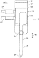
- Fig. 3 is a side elevation of the attaching head 2 viewed from the guiding head 3 side.
- the attaching head 2 according to this embodiment is a so-called nozzle head.
- This attaching head 2 includes a base 22, a component gripper 26, a moving device 23 which moves the component gripper 26 with respect to the base 22 in a first direction(s) 99, and an operating member 25 provided to the component gripper 26.
- the first direction 99 is a direction parallel to opening axes of the through-holes of the electronic substrate, i.e., a direction perpendicular to a surface of the electronic substrate on which the electronic component 9 is attached, and is generally a vertical or up-and-down direction.
- the base 22 is a plate member having a main surface parallel to the first directions 99.
- An interface plate 21 is coupled to the base 22. This interface plate 21 is connected with an interface on the attaching head moving mechanism 102 side. Note that, the interface plate 21 may be omitted depending on the form of the attaching head moving mechanism 102, and the base 22 may be directly connected to the attaching head moving mechanism 102.
- the moving device 23 is a so-called linear motion device.
- the moving device 23 includes an air cylinder 231 fixed to the base 22, a rod 232 which extends and contracts from/to the air cylinder 231 in the first directions 99, and a slider 233 coupled to the rod 232.
- a rail 234 extending in the first directions 99 is formed in a casing of the air cylinder 231 to guide the slider 233.
- the air cylinder 231 is connected with an air source 238 via piping 237, and compressed air is supplied from the air source 238 (see Fig. 7 ).
- An electromagnetic valve 236 which switches the compressed air to the air cylinder 231 between "supplying" and “discharging” is formed in the piping 237.
- the rod 232 extends and contracts by the supplying and discharging of the compressed air to the air cylinder 231.
- the slider 233 coupled to the rod 232 slides on the rail 234 in association with the expansion and contraction of the rod 232 to move in the first directions 99.
- the component gripper 26 includes an arm 260 extending in the first directions 99, and a suction nozzle 261 provided to a tip-end part of the arm 260.
- the suction nozzle 261 is connected to a negative pressure source 268 via the piping 267 (see Fig. 7 ).
- the piping 267 is provided with a changeover valve 266 which switches between communication/block of the suction nozzle 261 and the negative pressure source 268.
- a base-end part of the arm 260 is coupled to the slider 233 of the moving device 23.
- the component gripper 26 moves with respect to the base 22 in the first directions 99, according to the movement of the slider 233 of the moving device 23.
- the operating member 25 is fixed to the component gripper 26 so that it moves integrally with the component gripper 26.
- the operating member 25 according to this embodiment is provided to the arm 260 of the component gripper 26, and projects from the component gripper 26 in a direction perpendicular to the first directions 99.
- the operating member 25 is an element which acts on a lead gripper 4 (described later) to open and close the lead gripper 4.
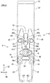
- Fig. 4 is a side elevation of the guiding head 3 viewed from the attaching head 2 side. As illustrated in Figs. 1 and 4 , the guiding head 3 includes a base 32 and the lead gripper 4 supported by the base 32.
- the base 32 is a plate member having a main surface parallel to the first directions 99.
- An interface plate 31 is coupled to the base 32. This interface plate 31 is connected with an interface on the guiding head moving mechanism 103 side. Note that the interface plate 31 may be omitted depending on the form of the guiding head moving mechanism 103, and the base 32 may be directly connected to the guiding head moving mechanism 103.
- the lead gripper 4 includes a pair of fingers 40 pivotably supported by the base 32, and a biasing member 47 which biases the pair of fingers 40 to open fingertips 421 of the pair of fingers 40 (i.e., separate the fingertips 421).
- the lead gripper 4 is a gripper which opens and closes by pivoting, and the pair of fingers 40 are structured so as to pinch the leads 92 of the electronic component 9 from both sides in second directions 98 perpendicular to the first directions 99.
- the second directions 98 are expressed as left-and-right directions, where the left side on the drawing paper of Fig. 4 may be expressed as the left, while the right side may similarly be expressed as the right.
- Each finger 40 has an operating part 41 provided to a base-end part, a grip part 42 provided to a tip-end part, and a support part 43 provided to an intermediate part between the base-end part and the tip-end part.
- Tip ends of the fingers 40 are fingertips 421, and a state where the fingertips 421 of the pair of fingers 40 are separated from each other is referred to as a state where the lead gripper 4 is "opened," while a state where the fingertips 421 of the pair of fingers 40 are abutted on or sufficiently close to each other is referred to as a state where the lead gripper 4 is "closed.”
- the pair of fingers 40 are pivotably supported by a pivot 35 fixed to the base 32 between the operating part 41 and the grip part 42 (i.e., the support part 43) so that the grip parts 42 are opposed to each other in the second directions 98 and the operating parts 41 are opposed to each other in the second directions 98.
- the pair of fingers 40 are constructed to be substantially symmetrical with respect to a straight line parallel to the first directions 99, which passes through the pivot 35.
- the support part 43 of the finger 40 protrudes toward the other finger, rather than other parts of the finger 40.
- the support part 43 of the right finger 40 protrudes to the left, rather than other parts of this finger 40, while the support part 43 of the left finger 40 protrudes to the right, rather than other parts of this finger 40.
- the support part 43 is coupled to an outer ring of a bearing unit 44, and the pivot 35 is inserted into an inner ring of the bearing unit 44.
- the fingers 40 are pivotable about the pivot 35 as a pivot center O.
- the operating part 41 of the finger 40 is provided with functional parts, such as a contact part 415, an acted part 416, and an escape part 412, in this order from the base-end side of a part opposed to the other finger 40.
- the contact parts 415 of the pair of fingers 40 are opposed to each other and are separated therebetween.
- the contact parts 415 may contact a rotation regulating block 33.
- the rotation regulating block 33 is located between the contact parts 415 of the pair of fingers 40 in the second directions 98 and located on an extended line of the pivot 35 in the first directions 99, and is fixed to the base 32.
- the rotation of the finger 40 in an opening direction is regulated by the contact part 415 contacting the rotation regulating block 33.
- the term "opening direction” as used herein refers to a rotating direction of the finger 40 when opening the lead gripper 4, while the opposite rotating direction of the finger 40 from the opening direction is referred to as "closing direction.”
- the acted parts 416 of the pair of fingers 40 oppose to each other and are separated therebetween, thereby forming a first gap G1 between the acted parts 416.
- a width of the first gap G 1 is smaller than a width of the operating member 25 in the second directions 98. Therefore, the operating member 25 located in the first gap G1 (i.e., between the acted parts 416) acts on the acted part 416.
- the escape parts 412 of the pair of fingers 40 oppose to each other and are separated therebetween, thereby forming a second gap G2 between the escape parts 412.
- a width of the second gap G2 is larger than the width of the operating member 25 in the second directions 98 which is inserted therein.
- the escape parts 412 is located away from the operating member 25 so that the operating member 25 located in the second gap G2 (i.e., between the escape parts 412) does not act on the escape parts 412.
- the operating member 25 in the second gap G2 is avoided from interfering with the operating parts 41 (particularly, the escape parts 412).
- the first gap G1 and the second gap G2 are aligned in the first directions 99.
- the second gap G2 is located on the electronic substrate side with respect to the first gap G1.
- the first gap G1 has a tapered shape which narrows from the second gap G2 by the pair of acted parts 416.
- the operating member 25 which moves from the second gap G2 to the first gap G1 slides on the acted parts 416, and reaches the first gap G1 while pushing open the operating parts 41 of the pair of fingers 40 to both left and right sides, i.e., closing the lead gripper 4.
- a rotation regulating hole 411 is formed in the operating part 41 of the finger 40.
- the rotation regulating hole 411 is an elongated hole extending in circumferential directions centering on the pivot center O.
- a rotation regulating pin 34 fixed to the base 32 is inserted into the rotation regulating hole 411.
- Rotation ranges of the fingers 40 are regulated by the rotation regulating holes 411 and the rotation regulating pins 34. Note that the rotation ranges of the fingers 40 may extend from a position where the fingertips 421 of the pair of fingers 40 contact each other to a position where the contact parts 415 contact the rotation regulating block 33.
- the grip part 42 provided below the pivot center O of the finger 40 is formed by a separate member detachably attached through a spacer 46 to a member forming the operating part 41 and the support part 43. These members may be coupled by fasteners 45, for example.
- the grip part 42 since the grip part 42 is formed by the separate member, the grip part 42 may be replaced according to the number and shape of the leads 92 of the electronic component 9.
- the spacer 46 is to adjust the position of each grip part 42 so that the fingertips 421 of the pair of fingers 40 are abutted on each other.
- each grip part 42 of the finger 40 is sufficiently separated from each other in the second directions 98 to an extent that the component gripper 26 of the attaching head 2 can be inserted therebetween.
- a tip-end portion of each grip part 42 is bent toward the other grip part 42 so that the pair of fingertips 421 oppose to each other in the second directions 98.
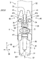
- Fig. 5 is an enlarged side elevation of the grip parts 42 of the fingers 40
- Fig. 6 is an enlarged plan view of the grip parts 42 of the fingers 40.
- the fingertips 421 provided to the pair of grip parts 42 abuts on or approaches to each other when the lead gripper 4 is closed.
- Corresponding number of guide grooves 422 to the number of the leads 92 of the electronic component 9 are formed in the fingertip 421.
- the opposing guide grooves 422 are put together to form guide holes into which the leads 92 of the electronic component 9 are inserted.
- Each guide hole has a portion which extends in the first directions 99 and is gradually reduced in the cross-sectional area toward the electronic substrate.
- the cross-sectional shape of a portion of the guide hole close to the electronic substrate is formed in a circular shape having a slightly larger inner diameter than an outer diameter of the leads 92 of the electronic component 9.
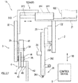
- Fig. 7 is a view illustrating a configuration of a control system of the electronic-component inserting device 1.
- the control device 6 is connected communicatably wiredly or wirelessly with the attaching head moving mechanism 102, the guiding head moving mechanism 103, the electromagnetic valve 236, the changeover valve 266, and a memory device 65.
- the control device 6 is a so-called a computer, and has an arithmetic processor, such as a CPU, and a memory, such as a ROM and a RAM (none of them is illustrated).
- the memory stores a control program executed by the control device 6, various fixed data, etc.
- the arithmetic processor transmits and receives data to/from external devices, such as an input device, an output device, and the memory device 65, which are not illustrated.
- the arithmetic processor accepts inputs of detection signals from various sensors and outputs a control signal to each controlled object.
- control device 6 the arithmetic processor reads and performs software, such as the programs stored in the memory and/or the memory device 65, to perform processing for controlling various operations of the electronic-component inserting device 1.
- the control device 6 may perform each processing by an integrated control with a single computer, or may perform each processing by a distributed control with a collaboration of a plurality of computers.
- the control device 6 may be comprised of a microcontroller, a programmable logic controller (PLC), etc.
- PLC programmable logic controller
- the control device 6 includes, as functional blocks, an attaching head position controller 61, a guiding head position controller 62, a movement controller 63, and a suction controller 64.
- an attaching head position controller 61 a guiding head position controller 62
- a movement controller 63 a movement controller 63
- a suction controller 64 a suction controller 64.
- FIG. 7 although these functional blocks are collectively illustrated as a single control device 6, the functional blocks may be implemented by one or more computers where each functional block or combination(s) of the plurality of functional blocks is independent.
- the attaching head position controller 61 controls operation of the attaching head moving mechanism 102 to move the attaching head 2 along a given path based on the program prestored in the memory device 65.
- the guiding head position controller 62 controls operation of the guiding head moving mechanism 103 to move the guiding head 3 along a given path based on the program prestored in the memory device 65.
- the movement controller 63 controls operation of the electromagnetic valve 236 based on the program prestored in the memory device 65 so that the component gripper 26 of the attaching head 2 moves vertically.
- the suction controller 64 controls operation of the changeover valve 266 based on the program prestored in the memory device 65 to cause the suction nozzle 261 of the attaching head 2 to generate the suction force.
- the control device 6 operates the attaching head 2 and the attaching head moving mechanism 102 to take out or extract the electronic component 9 from the component feeding device (not illustrated) and hold it.
- the attaching head moving mechanism 102 moves the attaching head 2 to an extraction position of the component feeding device.
- the attaching head 2 reaches the extraction position, it causes the suction nozzle 261 to generate the suction force, and suck and hold the electronic component 9 by the suction nozzle 261.
- the control device 6 operates the guiding head moving mechanism 103 to move the lead gripper 4 to a given attaching position of the electronic substrate.
- the guiding head moving mechanism 103 moves the lead gripper 4 to the given attaching position
- the electronic substrate may be moved. That is, the attaching head 2 and the electronic substrate move relatively to each other. This positioning of the lead gripper 4 may be performed simultaneously with the extracting and holding operation of the electronic component 9 of the attaching head 2.
- the lead gripper 4 which moved to the given attaching position is open. Note that, in the lead gripper 4 positioned at the given attaching position, when the lead gripper 4 is closed, the guide holes between the fingertips 421 are located near openings of the through-holes of the electronic substrate and on the opening axes, respectively.
- the control device 6 operates the attaching head moving mechanism 102 to insert the operating member 25 of the attaching head 2 into the second gap G2 of the lead gripper 4.
- the attaching head moving mechanism 102 may change the position and posture of the attaching head 2 so that the base 32 of the guiding head 3 and the base 32 of the attaching head 2 oppose to each other, position the attaching head 2 so that the second gap G2 of the lead gripper 4 and the operating member 25 of the attaching head 2 are located on the same straight line, and bring the attaching head 2 close to the lead gripper 4 to insert the operating member 25 into the second gap G2.
- the guiding head 3 may move. That is, the attaching head 2 and the guiding head 3 may move relatively to each other, and the electronic component 9 may be located at a given attaching position in a state where the operating member 25 is inserted into the second gap G2.
- the second gap G2 of the lead gripper 4 is formed in a concaved part into which the operating member 25 is inserted.
- This concaved part may be used as a positioning hole of the component gripper 26 with respect to the lead gripper 4.
- Fig. 8 is a side elevation of the guiding head 3 viewed from the attaching head 2 side when the operating member 25 is located in the second gap G2
- Fig. 9 is a front elevation of the electronic-component inserting device 1 when the operating member 25 is located in the second gap G2.
- the operating member 25 is virtually illustrated by a hatched two-dot chain line circle
- the component gripper 26 and the electronic component 9 sucked and held by the component gripper 26 are virtually illustrated by a two-dot chain line.
- the operating member 25 when the operating member 25 is fitted in the second gap G2, the operating member 25 does not act on the finger 40, but the lead gripper 4 is opened by a biasing force of the biasing member 47. Moreover, when the operating member 25 is fitted in the second gap G2, the component gripper 26 holding the electronic component 9 is located between the pair of grip parts 42, and the leads 92 of the electronic component 9 are located substantially on the opening axes of the through-holes of the electronic substrate, respectively.
- Fig. 10 is a side elevation of the guiding head 3 viewed from the attaching head 2 side when the operating member 25 is located in the first gap G1.
- the operating member 25 is virtually illustrated by a hatched two-dot-chain line circle, and the component gripper 26 and the electronic component 9 sucked and held by the component gripper 26 are virtually illustrated by a two-dot chain line.
- the operating member 25 located in the first gap G1 acts on the acted parts 416 in the operating parts 41 of the lead gripper 4.
- the operating member 25 may act on the contact parts 415. That is, the acted parts in the operating parts 41 of the lead gripper 4, on which the operating member 25 acts may be the acted parts 416, or the acted parts 416 and the contact parts 415.
- the control device 6 operates the attaching head 2 so that the operating member 25 moves from the second gap G2 to the first gap G1 with respect to the lead gripper 4.
- the component gripper 26 moves by the operation of the moving device 23, and in association with this movement, the operating member 25 moves with respect to the lead gripper 4.
- the guiding head moving mechanism 103 may move the operating member 25 and the component gripper 26 relatively to the lead gripper 4, instead of the moving device 23.
- the operating member 25 moves from the second gap G2 to the first gap G1
- the operating member 25 contacts the pair of acted parts 416 of the lead gripper 4 to extend a space between the pair of acted parts 416.
- the fingers 40 of the lead gripper 4 rotates in the closing direction to transit the lead gripper 4 from the opened state to the closed state.
- the fingertips 421 abut on each other.
- the electronic component 9 held by the component gripper 26 moves in the first directions 99 so as to separate from the electronic substrate, where the leads 92 fit into the guide grooves 422 of the lead gripper 4. Then, in the closed lead gripper 4, the leads 92 of the electronic component 9 are inserted into the guide holes formed by the guide grooves 422. Thus, even if the leads 92 are slightly bent or curved, the leads 92 are corrected to become straight by being pinched between the pair of fingers 40.
- the control device 6 moves the component gripper 26 to the attaching head 2 so that the leads 92 of the electronic component 9 are inserted into the through-holes of the electronic substrate.
- the component gripper 26 moves in the first directions 99 so as to approach the electronic substrate by the operation of the moving device 23.
- the component gripper 26 may be lowered by the operation of the attaching head moving mechanism 102.
- the electronic component 9 sucked and held by the component gripper 26 moves toward the electronic substrate in association with the movement of the component gripper 26.
- the leads 92 of the electronic component 9 are inserted into the through-holes of the electronic substrate.
- the operating member 25 moves from the first gap G1 to the second gap G2 so that the closed lead gripper 4 opens.
- the opening operation of the lead gripper 4 is synchronized with the insertion of the leads 92 of the electronic component 9.
- the leads 92 have still been gripped by the lead gripper 4. Therefore, the leads 92 of the electronic component 9 are inserted into the through-holes of the electronic substrate, while being guided by the guide holes of the lead gripper 4.
- the lead gripper 4 is open and, thus, the movement of the main body of the electronic component 9 is not obstructed by the lead gripper 4.
- the electronic-component inserting device 1 of this embodiment includes the component gripper 26 which holds the main body 91 of the electronic component 9, the operating member 25 provided to the component gripper 26, the lead gripper 4 which grips the leads 92 of the electronic component 9 held by the component gripper 26, and the moving device 23 which moves the component gripper 26 in the first directions 99 relatively to the lead gripper 4.
- the lead gripper 4 has the pair of fingers 40 which pinches the leads 92 of the electronic component 9 from both sides in the second directions 98 perpendicular to the first directions 99, the biasing member 47 which biases the fingertips 421 of the finger 40 to open, and the acted part 416 provided to the finger 40, which receives the acting force from the operating member 25 so that the fingertips 421 of the finger 40 are closed.
- the lead gripper 4 receives the acting force from the operating member 25 to close the fingertips 421 of the pair of fingers 40. That is, an actuator for exclusive use for opening and closing the lead gripper 4 is not provided, but the lead gripper 4 is mechanically opened and closed by the operating member 25 which integrally moves with the component gripper 26. Therefore, the timings of the movement of the component gripper 26 and the opening and closing of the lead gripper 4 are synchronized with each other, and their cooperation is promised. Moreover, since the actuator for exclusive use for opening and closing the lead gripper 4 is not provided, a controller for this actuator is unnecessary.
- the finger 40 includes the grip part 42 provided to the tip-end part, and the operating part 41 provided to the base-end part.
- the finger 40 is pivotably supported between the operating part 41 and the grip part 42 so that the grip parts 42 oppose to each other in the second directions 98, and the operating parts 41 oppose to each other in the second directions 98.
- the acted part 416 on which the operating member 25 located between the operating parts 41 acts, the escape part 412 which avoids the interference with the operating member 25 so that the operating member 25 located between the operating parts 41 does not act on the escape part 412 are formed adjacent to each other in the first directions 99.
- the pair of fingers 40 of the lead gripper 4 can be opened and closed.
- the first directions 99 are parallel to the opening axes of the through-holes of the electronic substrate, and the escape part 412 is provided at the electronic substrate side with respect to the acted part 416.
- the lead gripper 4 releases the gripped leads 92. Therefore, the lead gripper 4 can certainly guide the leads 92 of the electronic component 9 which are about to be inserted or are being inserted into the through-holes of the electronic substrate. Moreover, the insertion of the electronic component 9 and the release of the leads 92 by the lead gripper 4 are performed simultaneously, thereby shortening the work hours.
- the concaved part (the second gap G2) into which the operating member 25 is inserted is formed by the escape part 412 of the lead gripper 4, and the electronic-component inserting device 1 includes the moving mechanism (the guiding head moving mechanism 103) which moves the lead gripper 4 relatively to the component gripper 26 so that the operating member 25 is inserted into and removed from the concaved part.
- the component gripper 26 is positioned with respect to the lead gripper 4. Therefore, although the component gripper 26 and the lead gripper 4 are constructed independently, a positional offset or error of the component gripper 26 with respect to the lead gripper 4 is prevented.
- the guide grooves 422 which are used as the guide holes of the leads 92 are formed in the fingertips 421 of the finger 40 when the fingertips 421 are abutted on each other.
- the guide hole has the portion which extends in the first directions 99 and is reduced in the diameter toward the electronic substrate.
- the leads 92 are bent or curved, the leads 92 are inserted into the through-holes of the electronic substrate while being corrected by the guide holes when the leads 92 are guided through the guide holes (the guide groove 422).
- the electronic-component inserting device 1 further includes the first moving mechanism (i.e., the attaching head moving mechanism 102) which moves the component gripper 26 relatively to the substrate, and the second moving mechanism (i.e., the guiding head moving mechanism 103) which moves the lead gripper 4 relatively to the component gripper 26.
- the first moving mechanism is one arm 12 of the dual-arm robot 10
- the second moving mechanism is the other arm 13 of the dual-arm robot 10.
- the timings of the movement of the component gripper 26 and the opening and closing of the lead gripper 4 is synchronized with each other, the component gripper 26 can be positioned to the lead gripper 4, and a breakdown of the cooperation of the component gripper 26 and the lead gripper 4 does not occur easily. Therefore, in the electronic-component inserting device 1 according to this embodiment, the electronic-component inserting device 1 utilizing the dual-arm robot 10, in which the component gripper 26 and the lead gripper 4 are distributed to the arms 12 and 13, respectively, is easily implemented.
- the moving mechanism 102 of the component gripper 26 and the moving mechanism 103 of the lead gripper 4 operate independently, for example, the positioning of the lead gripper 4 to the electronic substrate, and the holding and conveyance of the electronic component 9 by the component gripper 26 are performed simultaneously, thereby shortening the work hours.
- the structure of the electronic-component inserting device 1 may be changed as follows, for example.
- the component gripper 26 is a so-called suction-type gripper which causes the suction nozzle 261 to generate the absorbing force by the negative pressure or vacuum to suck and hold the electronic component 9 by the absorbing force at the suction nozzle 261.
- the component gripper 26 is not limited to this embodiment, it may be a grip-type gripper (mechanical gripper), for example.
- the operating member 25 is a single pin-shaped member, the operating member 25 may be comprised of a plurality of members.
- the operating members 25 which act on the respective pair of fingers 40 may be provided.
- the attaching head moving mechanism 102 and the guiding head moving mechanism 103 are the horizontal articulated robot arms 12 and 13, respectively, the attaching head moving mechanism 102 and the guiding head moving mechanism 103 are not limited to this structure.
- the attaching head moving mechanism 102 and the guiding head moving mechanism 103 may be vertical articulated robot arms.
- the attaching head moving mechanism 102 and the guiding head moving mechanism 103 are not limited to the robot arms.
- the attaching head moving mechanism 102 may be a robot arm
- the guiding head moving mechanism 103 may be a linear-motion mechanism attached to the robot arm.
- Fig. 11 illustrates an electronic-component inserting device 1A according to Modification 1 in which the attaching head moving mechanism 102 is a robot arm and the guiding head moving mechanism 103 is a linear-motion mechanism 51.
- the linear-motion mechanism 51 includes a cylinder 511 fixed to the interface plate 21, a rod 512 which extends and contracts the cylinder 511 horizontally, and a slider 513 attached to the rod 512.
- a horizontal rail 514 which guides the slider 513 is formed in a casing of the cylinder 511.
- a base 32 of the guiding head 3 is fixed to the slider 513.
- FIG. 12 illustrates an electronic-component inserting device 1B according to Modification 2 in which the guiding head 3 is combined with the attaching head 2.
- the base 32 of the guiding head 3 is fixed to the interface plate 21 fixed to the base 22 of the attaching head 2.
- the operating member 25 in the stationary state is fitted into the second gap G2 of the lead gripper 4.
Landscapes
- Engineering & Computer Science (AREA)
- Manufacturing & Machinery (AREA)
- Microelectronics & Electronic Packaging (AREA)
- Robotics (AREA)
- Mechanical Engineering (AREA)
- Supply And Installment Of Electrical Components (AREA)
- Manipulator (AREA)
Abstract
Description
- The present disclosure relates to an inserting device which inserts leads of an electronic component with the leads into a substrate.
- There is a so-called "lead component" in which leads are connected to electrodes of a main body of an electronic component, among electronic components. Such an electronic component is fixed to an electronic substrate by inserting its leads into the through-holes formed in the electronic substrate and soldering the connections from the back side of the electronic substrate. Conventionally, the electronic-component inserting devices have been known which automatically attach electronic components to an electronic substrate by inserting leads into through-holes of the electronic substrate.
Patent Document 1 discloses this kind of technology. - The electronic-component attaching device (electronic-component inserting device) disclosed in
Patent Document 1 cuts leads of an electronic component, and automatically attaches the electronic component to an electronic substrate. This electronic-component attaching device includes a gripper having a pair of arms, a pressing member which relatively displaces vertically with respect to the pair of arms, and a moving mechanism which relatively moves the gripper and the electronic substrate. The pair of arms have a pair of support parts which sandwich the main body of the electronic component at base-end parts, and a pair of blade parts which sandwich the leads at tip-end parts. The electronic-component attaching device first holds the main body of the electronic component by the pair of support parts by closing the pair of arms, and cuts and holds the leads by the pair of blade parts. Then, the device presses the electronic component toward the electronic substrate by the pressing member while opening the pair of arms to attach the electronic component to the electronic substrate. - [Patent Document 1]
JP1994-034300U - In the device of
Patent Document 1, each of the gripper, the pressing member, and the moving mechanism is provided with an actuator for exclusive use, and the plurality of actuators are controlled so that they synchronizedly operate. - Meanwhile, the present inventors have examined constructing an electronic-component inserting device using a dual-arm robot. That is, an end effector is attached to a hand part of each arm of the dual-arm robot, and the dual-arm robot is operated to function as an electronic-component inserting device. In such an electronic-component inserting device, a component holding function to hold the electronic component and insert the electronic component into the substrate, and a lead guiding function to guide the leads of the electronic component are possible to be distributed to respective arms. However, if distributing the component holding function and the lead guiding function to the respective arms, which are functions to cooperate with each other, operations may not be performed normally when a time lag occurs between the functional parts.
- According to one aspect of the present disclosure, an electronic-component inserting device is provided, which inserts an electronic component with leads into through-holes of a substrate. The device includes a component gripper configured to hold a main body of the electronic component, an operating member provided to the component gripper, a lead gripper configured to grip the leads of the electronic component held by the component gripper, and a moving device configured to move the component gripper in a first direction relatively to the lead gripper. The lead gripper has a pair of fingers configured to pinch the leads from both sides in second directions perpendicular to the first direction, and a biasing member configured to bias the pair of fingers so that fingertips of the fingers are opened. The fingers are provided with acted parts on which an acting force from the operating member acts so that the fingertips of the fingers are closed.
- In the electronic-component inserting device, when the operating member moves in the first direction in association with the component gripper, the lead gripper receives the acting force from the operating member to close the fingertips of the pair of fingers. That is, an actuator for exclusive use for opening and closing the lead gripper is not provided, but the lead gripper is mechanically opened and closed by the operating member which integrally moves with the component gripper. Therefore, the timings of the movement of the component gripper and the opening and closing of the lead gripper are synchronized with each other, and their cooperation is promised. Moreover, since the actuator for exclusive use for opening and closing the lead gripper is not provided, a controller for this actuator is unnecessary. Moreover, the electronic-component inserting device utilizing a dual-arm robot, in which the component gripper and the lead gripper are distributed to arms, respectively, is easily implemented.
- According to the present disclosure, in the electronic-component inserting device provided with the component gripper which holds the electronic component and inserts it into the substrate, and the lead gripper which guides the leads of the electronic component, the timings of the movement of the component gripper and opening and closing of the lead gripper is synchronized without controlling the opening and closing of the lead gripper.
-
-
Fig. 1 is a front elevation schematically illustrating a structure of an electronic-component inserting device according to one embodiment of the present disclosure. -
Fig. 2 is a view illustrating one example of the electronic-component inserting device in which both of an attaching head moving mechanism and a guiding head moving mechanism are robot arms. -
Fig. 3 is a side elevation of the attaching head viewed from the guiding head side. -
Fig. 4 is a side elevation of the guiding head viewed from the attaching head side. -
Fig. 5 is an enlarged side elevation of grip parts of fingers. -
Fig. 6 is an enlarged plan view of the grip parts of the fingers. -
Fig. 7 is a view illustrating a configuration of a control system of the electronic-component inserting device. -
Fig. 8 is a side elevation of the guiding head viewed from the attaching head side when an operating member is in an open position. -
Fig. 9 is a front elevation of the electronic-component inserting device when the operating member is in the open position. -
Fig. 10 is a side elevation of the guiding head viewed from the attaching head side when the operating member is in a closed position. -
Fig. 11 is a front elevation schematically illustrating a structure of an electronic-component inserting device according toModification 1. -
Fig. 12 is a front elevation schematically illustrating a structure of an electronic-component inserting device according toModification 2. - Next, one embodiment of the present disclosure is described with reference to the drawings. An electronic-component inserting device according to this embodiment of the present disclosure is a device to automatically attach an electronic component with leads to an electronic substrate. Particularly, the electronic-component inserting device performs a work in which it takes out the electronic component from a component feeding device and holds the electronic component, conveys the electronic component to a given position on the electronic substrate, adjusts the leads of the electronic component, and inserts the leads into given through-holes formed in the electronic substrate.
-
Fig. 1 is a front elevation schematically illustrating the structure of the electronic-componentinserting device 1 according to this embodiment of the present disclosure, andFig. 2 is a view illustrating one example of the electronic-componentinserting device 1 in which both of an attachinghead moving mechanism 102 and a guidinghead moving mechanism 103 arearms Fig. 1 , the electronic-componentinserting device 1 includes an attachinghead 2, a guidinghead 3, the attachinghead moving mechanism 102, the guidinghead moving mechanism 103, and acontrol device 6 that governs operations of these elements. - The attaching
head 2 holds anelectronic component 9 to be attached to the electronic substrate, and inserts leads 92 of the currently-holdingelectronic component 9 into the given through-holes of the electronic substrate. The attachinghead moving mechanism 102 is a mechanism which moves the attachinghead 2 relatively to the electronic substrate so that theelectronic component 9 moves to the given attaching position on the electronic substrate. - Moreover, the guiding
head 3 adjusts theleads 92 of theelectronic component 9 held by the attachinghead 2, and guides theleads 92 to the through-holes. The guidinghead moving mechanism 103 is a mechanism which moves the guidinghead 3 relatively to the attaching head 2 (or the electronic substrate). - As illustrated in
Fig. 2 , the electronic-component inserting device 1 according to this embodiment is constructed using a dual-arm robot 10. The dual-arm robot 10 has apedestal 11 and a pair ofrobot arms pedestal 11. The attachinghead 2 is attached to a hand part of onearm 12 among the pair ofarms head 3 is attached to a hand part of theother arm 13. That is, in this embodiment, onearm 12 of the dual-arm robot 10 functions as the attachinghead moving mechanism 102, and theother arm 13 functions as the guidinghead moving mechanism 103. Thearms arms head 2, the guidinghead 3, and thecontrol device 6 will be particularly described in detail among the elements of the electronic-component inserting device 1. -
Fig. 3 is a side elevation of the attachinghead 2 viewed from the guidinghead 3 side. As illustrated inFigs. 1 and3 , the attachinghead 2 according to this embodiment is a so-called nozzle head. This attachinghead 2 includes abase 22, acomponent gripper 26, a movingdevice 23 which moves thecomponent gripper 26 with respect to the base 22 in a first direction(s) 99, and an operatingmember 25 provided to thecomponent gripper 26. Here, "thefirst direction 99" is a direction parallel to opening axes of the through-holes of the electronic substrate, i.e., a direction perpendicular to a surface of the electronic substrate on which theelectronic component 9 is attached, and is generally a vertical or up-and-down direction. - The
base 22 is a plate member having a main surface parallel to thefirst directions 99. Aninterface plate 21 is coupled to thebase 22. Thisinterface plate 21 is connected with an interface on the attachinghead moving mechanism 102 side. Note that, theinterface plate 21 may be omitted depending on the form of the attachinghead moving mechanism 102, and the base 22 may be directly connected to the attachinghead moving mechanism 102. - The moving
device 23 is a so-called linear motion device. The movingdevice 23 includes anair cylinder 231 fixed to thebase 22, arod 232 which extends and contracts from/to theair cylinder 231 in thefirst directions 99, and aslider 233 coupled to therod 232. Arail 234 extending in thefirst directions 99 is formed in a casing of theair cylinder 231 to guide theslider 233. Theair cylinder 231 is connected with anair source 238 via piping 237, and compressed air is supplied from the air source 238 (seeFig. 7 ). Anelectromagnetic valve 236 which switches the compressed air to theair cylinder 231 between "supplying" and "discharging" is formed in thepiping 237. Therod 232 extends and contracts by the supplying and discharging of the compressed air to theair cylinder 231. Theslider 233 coupled to therod 232 slides on therail 234 in association with the expansion and contraction of therod 232 to move in thefirst directions 99. - The
component gripper 26 includes anarm 260 extending in thefirst directions 99, and asuction nozzle 261 provided to a tip-end part of thearm 260. Thesuction nozzle 261 is connected to anegative pressure source 268 via the piping 267 (seeFig. 7 ). The piping 267 is provided with achangeover valve 266 which switches between communication/block of thesuction nozzle 261 and thenegative pressure source 268. When thesuction nozzle 261 communicates with thenegative pressure source 268, a suction force is generated at thesuction nozzle 261 by negative pressure. - A base-end part of the
arm 260 is coupled to theslider 233 of the movingdevice 23. Thus, thecomponent gripper 26 moves with respect to the base 22 in thefirst directions 99, according to the movement of theslider 233 of the movingdevice 23. - The operating
member 25 is fixed to thecomponent gripper 26 so that it moves integrally with thecomponent gripper 26. The operatingmember 25 according to this embodiment is provided to thearm 260 of thecomponent gripper 26, and projects from thecomponent gripper 26 in a direction perpendicular to thefirst directions 99. The operatingmember 25 is an element which acts on a lead gripper 4 (described later) to open and close thelead gripper 4. -
Fig. 4 is a side elevation of the guidinghead 3 viewed from the attachinghead 2 side. As illustrated inFigs. 1 and4 , the guidinghead 3 includes abase 32 and thelead gripper 4 supported by thebase 32. - The
base 32 is a plate member having a main surface parallel to thefirst directions 99. Aninterface plate 31 is coupled to thebase 32. Thisinterface plate 31 is connected with an interface on the guidinghead moving mechanism 103 side. Note that theinterface plate 31 may be omitted depending on the form of the guidinghead moving mechanism 103, and the base 32 may be directly connected to the guidinghead moving mechanism 103. - The
lead gripper 4 includes a pair offingers 40 pivotably supported by thebase 32, and a biasingmember 47 which biases the pair offingers 40 to openfingertips 421 of the pair of fingers 40 (i.e., separate the fingertips 421). Thelead gripper 4 is a gripper which opens and closes by pivoting, and the pair offingers 40 are structured so as to pinch theleads 92 of theelectronic component 9 from both sides insecond directions 98 perpendicular to thefirst directions 99. Note that, herein, for convenience of description, thesecond directions 98 are expressed as left-and-right directions, where the left side on the drawing paper ofFig. 4 may be expressed as the left, while the right side may similarly be expressed as the right. - Each
finger 40 has an operatingpart 41 provided to a base-end part, agrip part 42 provided to a tip-end part, and asupport part 43 provided to an intermediate part between the base-end part and the tip-end part. Tip ends of thefingers 40 arefingertips 421, and a state where thefingertips 421 of the pair offingers 40 are separated from each other is referred to as a state where thelead gripper 4 is "opened," while a state where thefingertips 421 of the pair offingers 40 are abutted on or sufficiently close to each other is referred to as a state where thelead gripper 4 is "closed." - The pair of
fingers 40 are pivotably supported by apivot 35 fixed to the base 32 between the operatingpart 41 and the grip part 42 (i.e., the support part 43) so that thegrip parts 42 are opposed to each other in thesecond directions 98 and the operatingparts 41 are opposed to each other in thesecond directions 98. The pair offingers 40 are constructed to be substantially symmetrical with respect to a straight line parallel to thefirst directions 99, which passes through thepivot 35. Thus, below, corresponding elements of the pair offingers 40 are denoted with the same reference numerals in the figures to omit redundant description. - The
support part 43 of thefinger 40 protrudes toward the other finger, rather than other parts of thefinger 40. In other words, thesupport part 43 of theright finger 40 protrudes to the left, rather than other parts of thisfinger 40, while thesupport part 43 of theleft finger 40 protrudes to the right, rather than other parts of thisfinger 40. Thesupport part 43 is coupled to an outer ring of a bearingunit 44, and thepivot 35 is inserted into an inner ring of the bearingunit 44. Thus, thefingers 40 are pivotable about thepivot 35 as a pivot center O. - The operating
part 41 of thefinger 40 is provided with functional parts, such as acontact part 415, an actedpart 416, and anescape part 412, in this order from the base-end side of a part opposed to theother finger 40. - The
contact parts 415 of the pair offingers 40 are opposed to each other and are separated therebetween. Thecontact parts 415 may contact arotation regulating block 33. Therotation regulating block 33 is located between thecontact parts 415 of the pair offingers 40 in thesecond directions 98 and located on an extended line of thepivot 35 in thefirst directions 99, and is fixed to thebase 32. The rotation of thefinger 40 in an opening direction is regulated by thecontact part 415 contacting therotation regulating block 33. The term "opening direction" as used herein refers to a rotating direction of thefinger 40 when opening thelead gripper 4, while the opposite rotating direction of thefinger 40 from the opening direction is referred to as "closing direction." - The acted
parts 416 of the pair offingers 40 oppose to each other and are separated therebetween, thereby forming a first gap G1 between the actedparts 416. A width of thefirst gap G 1 is smaller than a width of the operatingmember 25 in thesecond directions 98. Therefore, the operatingmember 25 located in the first gap G1 (i.e., between the acted parts 416) acts on the actedpart 416. - The
escape parts 412 of the pair offingers 40 oppose to each other and are separated therebetween, thereby forming a second gap G2 between theescape parts 412. A width of the second gap G2 is larger than the width of the operatingmember 25 in thesecond directions 98 which is inserted therein. In other words, theescape parts 412 is located away from the operatingmember 25 so that the operatingmember 25 located in the second gap G2 (i.e., between the escape parts 412) does not act on theescape parts 412. As a result, the operatingmember 25 in the second gap G2 is avoided from interfering with the operating parts 41 (particularly, the escape parts 412). - The first gap G1 and the second gap G2 are aligned in the
first directions 99. The second gap G2 is located on the electronic substrate side with respect to the first gap G1. In a state where the operatingmember 25 does not act on thefingers 40 and thelead gripper 4 is opened, the first gap G1 has a tapered shape which narrows from the second gap G2 by the pair of actedparts 416. Thus, the operatingmember 25 which moves from the second gap G2 to the first gap G1 slides on the actedparts 416, and reaches the first gap G1 while pushing open the operatingparts 41 of the pair offingers 40 to both left and right sides, i.e., closing thelead gripper 4. - Further, a
rotation regulating hole 411 is formed in the operatingpart 41 of thefinger 40. Therotation regulating hole 411 is an elongated hole extending in circumferential directions centering on the pivot center O. Arotation regulating pin 34 fixed to thebase 32 is inserted into therotation regulating hole 411. Rotation ranges of thefingers 40 are regulated by therotation regulating holes 411 and the rotation regulating pins 34. Note that the rotation ranges of thefingers 40 may extend from a position where thefingertips 421 of the pair offingers 40 contact each other to a position where thecontact parts 415 contact therotation regulating block 33. - The
grip part 42 provided below the pivot center O of thefinger 40 is formed by a separate member detachably attached through aspacer 46 to a member forming the operatingpart 41 and thesupport part 43. These members may be coupled byfasteners 45, for example. Thus, since thegrip part 42 is formed by the separate member, thegrip part 42 may be replaced according to the number and shape of theleads 92 of theelectronic component 9. Note that thespacer 46 is to adjust the position of eachgrip part 42 so that thefingertips 421 of the pair offingers 40 are abutted on each other. - Between the opened
grip parts 42 of thefinger 40 are sufficiently separated from each other in thesecond directions 98 to an extent that thecomponent gripper 26 of the attachinghead 2 can be inserted therebetween. A tip-end portion of eachgrip part 42 is bent toward theother grip part 42 so that the pair offingertips 421 oppose to each other in thesecond directions 98. -
Fig. 5 is an enlarged side elevation of thegrip parts 42 of thefingers 40, andFig. 6 is an enlarged plan view of thegrip parts 42 of thefingers 40. As illustrated inFigs. 5 and 6 , thefingertips 421 provided to the pair ofgrip parts 42 abuts on or approaches to each other when thelead gripper 4 is closed. Corresponding number ofguide grooves 422 to the number of theleads 92 of theelectronic component 9 are formed in thefingertip 421. When thefingertips 421 abut on each other, the opposingguide grooves 422 are put together to form guide holes into which the leads 92 of theelectronic component 9 are inserted. Each guide hole has a portion which extends in thefirst directions 99 and is gradually reduced in the cross-sectional area toward the electronic substrate. The cross-sectional shape of a portion of the guide hole close to the electronic substrate is formed in a circular shape having a slightly larger inner diameter than an outer diameter of theleads 92 of theelectronic component 9. -
Fig. 7 is a view illustrating a configuration of a control system of the electronic-component inserting device 1. As illustrated inFig. 7 , thecontrol device 6 is connected communicatably wiredly or wirelessly with the attachinghead moving mechanism 102, the guidinghead moving mechanism 103, theelectromagnetic valve 236, thechangeover valve 266, and amemory device 65. - The
control device 6 is a so-called a computer, and has an arithmetic processor, such as a CPU, and a memory, such as a ROM and a RAM (none of them is illustrated). The memory stores a control program executed by thecontrol device 6, various fixed data, etc. The arithmetic processor transmits and receives data to/from external devices, such as an input device, an output device, and thememory device 65, which are not illustrated. Moreover, the arithmetic processor accepts inputs of detection signals from various sensors and outputs a control signal to each controlled object. In thecontrol device 6, the arithmetic processor reads and performs software, such as the programs stored in the memory and/or thememory device 65, to perform processing for controlling various operations of the electronic-component inserting device 1. Note that thecontrol device 6 may perform each processing by an integrated control with a single computer, or may perform each processing by a distributed control with a collaboration of a plurality of computers. Moreover, thecontrol device 6 may be comprised of a microcontroller, a programmable logic controller (PLC), etc. - The
control device 6 includes, as functional blocks, an attachinghead position controller 61, a guidinghead position controller 62, amovement controller 63, and asuction controller 64. InFig. 7 , although these functional blocks are collectively illustrated as asingle control device 6, the functional blocks may be implemented by one or more computers where each functional block or combination(s) of the plurality of functional blocks is independent. - The attaching
head position controller 61 controls operation of the attachinghead moving mechanism 102 to move the attachinghead 2 along a given path based on the program prestored in thememory device 65. - The guiding
head position controller 62 controls operation of the guidinghead moving mechanism 103 to move the guidinghead 3 along a given path based on the program prestored in thememory device 65. - The
movement controller 63 controls operation of theelectromagnetic valve 236 based on the program prestored in thememory device 65 so that thecomponent gripper 26 of the attachinghead 2 moves vertically. - The
suction controller 64 controls operation of thechangeover valve 266 based on the program prestored in thememory device 65 to cause thesuction nozzle 261 of the attachinghead 2 to generate the suction force. - Next, the method of operating the electronic-
component inserting device 1 having the structure described above is described. - First, the
control device 6 operates the attachinghead 2 and the attachinghead moving mechanism 102 to take out or extract theelectronic component 9 from the component feeding device (not illustrated) and hold it. Here, the attachinghead moving mechanism 102 moves the attachinghead 2 to an extraction position of the component feeding device. When the attachinghead 2 reaches the extraction position, it causes thesuction nozzle 261 to generate the suction force, and suck and hold theelectronic component 9 by thesuction nozzle 261. - Next, the
control device 6 operates the guidinghead moving mechanism 103 to move thelead gripper 4 to a given attaching position of the electronic substrate. Here, although the guidinghead moving mechanism 103 moves thelead gripper 4 to the given attaching position, the electronic substrate may be moved. That is, the attachinghead 2 and the electronic substrate move relatively to each other. This positioning of thelead gripper 4 may be performed simultaneously with the extracting and holding operation of theelectronic component 9 of the attachinghead 2. - The
lead gripper 4 which moved to the given attaching position is open. Note that, in thelead gripper 4 positioned at the given attaching position, when thelead gripper 4 is closed, the guide holes between thefingertips 421 are located near openings of the through-holes of the electronic substrate and on the opening axes, respectively. - Next, the
control device 6 operates the attachinghead moving mechanism 102 to insert the operatingmember 25 of the attachinghead 2 into the second gap G2 of thelead gripper 4. Here, the attachinghead moving mechanism 102 may change the position and posture of the attachinghead 2 so that thebase 32 of the guidinghead 3 and thebase 32 of the attachinghead 2 oppose to each other, position the attachinghead 2 so that the second gap G2 of thelead gripper 4 and the operatingmember 25 of the attachinghead 2 are located on the same straight line, and bring the attachinghead 2 close to thelead gripper 4 to insert the operatingmember 25 into the second gap G2. Note that, in this embodiment, although the attachinghead 2 moves, the guidinghead 3 may move. That is, the attachinghead 2 and the guidinghead 3 may move relatively to each other, and theelectronic component 9 may be located at a given attaching position in a state where the operatingmember 25 is inserted into the second gap G2. - In this embodiment, the second gap G2 of the
lead gripper 4 is formed in a concaved part into which the operatingmember 25 is inserted. This concaved part may be used as a positioning hole of thecomponent gripper 26 with respect to thelead gripper 4. As described above, when inserting the operatingmember 25 of the attachinghead 2 into the second gap G2 of thelead gripper 4, a wrist of thearm 12 which is the attachinghead moving mechanism 102 for moving thecomponent gripper 26 is made flexibly displaceable by a compliance function, while a wrist of thearm 13 which is the guidinghead moving mechanism 103 for moving thelead gripper 4 is fixed. In this state, when the operatingmember 25 of the attachinghead 2 is inserted into the second gap G2 of thelead gripper 4, thecomponent gripper 26 is positioned with respect to thelead gripper 4. -
Fig. 8 is a side elevation of the guidinghead 3 viewed from the attachinghead 2 side when the operatingmember 25 is located in the second gap G2, andFig. 9 is a front elevation of the electronic-component inserting device 1 when the operatingmember 25 is located in the second gap G2. InFig. 8 , the operatingmember 25 is virtually illustrated by a hatched two-dot chain line circle, and thecomponent gripper 26 and theelectronic component 9 sucked and held by thecomponent gripper 26 are virtually illustrated by a two-dot chain line. - As illustrated in
Figs. 8 and9 , when the operatingmember 25 is fitted in the second gap G2, the operatingmember 25 does not act on thefinger 40, but thelead gripper 4 is opened by a biasing force of the biasingmember 47. Moreover, when the operatingmember 25 is fitted in the second gap G2, thecomponent gripper 26 holding theelectronic component 9 is located between the pair ofgrip parts 42, and theleads 92 of theelectronic component 9 are located substantially on the opening axes of the through-holes of the electronic substrate, respectively. -
Fig. 10 is a side elevation of the guidinghead 3 viewed from the attachinghead 2 side when the operatingmember 25 is located in the first gap G1. InFig. 10 , the operatingmember 25 is virtually illustrated by a hatched two-dot-chain line circle, and thecomponent gripper 26 and theelectronic component 9 sucked and held by thecomponent gripper 26 are virtually illustrated by a two-dot chain line. As illustrated inFig. 10 , the operatingmember 25 located in the first gap G1 acts on the actedparts 416 in the operatingparts 41 of thelead gripper 4. Here, the operatingmember 25 may act on thecontact parts 415. That is, the acted parts in the operatingparts 41 of thelead gripper 4, on which the operatingmember 25 acts may be the actedparts 416, or the actedparts 416 and thecontact parts 415. - The
control device 6 operates the attachinghead 2 so that the operatingmember 25 moves from the second gap G2 to the first gap G1 with respect to thelead gripper 4. Here, in the attachinghead 2, thecomponent gripper 26 moves by the operation of the movingdevice 23, and in association with this movement, the operatingmember 25 moves with respect to thelead gripper 4. Note that the guidinghead moving mechanism 103 may move the operatingmember 25 and thecomponent gripper 26 relatively to thelead gripper 4, instead of the movingdevice 23. - In the process where the operating
member 25 moves from the second gap G2 to the first gap G1, the operatingmember 25 contacts the pair of actedparts 416 of thelead gripper 4 to extend a space between the pair of actedparts 416. Thus, thefingers 40 of thelead gripper 4 rotates in the closing direction to transit thelead gripper 4 from the opened state to the closed state. When thelead gripper 4 is closed, thefingertips 421 abut on each other. - In the process where the
lead gripper 4 closes, theelectronic component 9 held by thecomponent gripper 26 moves in thefirst directions 99 so as to separate from the electronic substrate, where the leads 92 fit into theguide grooves 422 of thelead gripper 4. Then, in theclosed lead gripper 4, theleads 92 of theelectronic component 9 are inserted into the guide holes formed by theguide grooves 422. Thus, even if the leads 92 are slightly bent or curved, theleads 92 are corrected to become straight by being pinched between the pair offingers 40. - At last, the
control device 6 moves thecomponent gripper 26 to the attachinghead 2 so that the leads 92 of theelectronic component 9 are inserted into the through-holes of the electronic substrate. Here, in the attachinghead 2, thecomponent gripper 26 moves in thefirst directions 99 so as to approach the electronic substrate by the operation of the movingdevice 23. Note that, instead of the movingdevice 23, thecomponent gripper 26 may be lowered by the operation of the attachinghead moving mechanism 102. - The
electronic component 9 sucked and held by thecomponent gripper 26 moves toward the electronic substrate in association with the movement of thecomponent gripper 26. Thus, theleads 92 of theelectronic component 9 are inserted into the through-holes of the electronic substrate. - Moreover, in association with the movement of the
component gripper 26, the operatingmember 25 moves from the first gap G1 to the second gap G2 so that theclosed lead gripper 4 opens. - The opening operation of the
lead gripper 4 is synchronized with the insertion of theleads 92 of theelectronic component 9. When the tip-end parts of theleads 92 of theelectronic component 9 are inserted into the through-holes of the electronic substrate, theleads 92 have still been gripped by thelead gripper 4. Therefore, theleads 92 of theelectronic component 9 are inserted into the through-holes of the electronic substrate, while being guided by the guide holes of thelead gripper 4. Moreover, when theelectronic component 9 lowers and amain body 91 thereof reaches above the electronic substrate, thelead gripper 4 is open and, thus, the movement of the main body of theelectronic component 9 is not obstructed by thelead gripper 4. - As described above, the electronic-
component inserting device 1 of this embodiment includes thecomponent gripper 26 which holds themain body 91 of theelectronic component 9, the operatingmember 25 provided to thecomponent gripper 26, thelead gripper 4 which grips theleads 92 of theelectronic component 9 held by thecomponent gripper 26, and the movingdevice 23 which moves thecomponent gripper 26 in thefirst directions 99 relatively to thelead gripper 4. Thelead gripper 4 has the pair offingers 40 which pinches theleads 92 of theelectronic component 9 from both sides in thesecond directions 98 perpendicular to thefirst directions 99, the biasingmember 47 which biases thefingertips 421 of thefinger 40 to open, and the actedpart 416 provided to thefinger 40, which receives the acting force from the operatingmember 25 so that thefingertips 421 of thefinger 40 are closed. - In the electronic-
component inserting device 1, when the operatingmember 25 moves in thefirst directions 99 in association with thecomponent gripper 26, thelead gripper 4 receives the acting force from the operatingmember 25 to close thefingertips 421 of the pair offingers 40. That is, an actuator for exclusive use for opening and closing thelead gripper 4 is not provided, but thelead gripper 4 is mechanically opened and closed by the operatingmember 25 which integrally moves with thecomponent gripper 26. Therefore, the timings of the movement of thecomponent gripper 26 and the opening and closing of thelead gripper 4 are synchronized with each other, and their cooperation is promised. Moreover, since the actuator for exclusive use for opening and closing thelead gripper 4 is not provided, a controller for this actuator is unnecessary. - Moreover, in the electronic-
component inserting device 1 according to this embodiment, thefinger 40 includes thegrip part 42 provided to the tip-end part, and the operatingpart 41 provided to the base-end part. Thefinger 40 is pivotably supported between the operatingpart 41 and thegrip part 42 so that thegrip parts 42 oppose to each other in thesecond directions 98, and the operatingparts 41 oppose to each other in thesecond directions 98. In this operatingpart 41, the actedpart 416 on which the operatingmember 25 located between the operatingparts 41 acts, theescape part 412 which avoids the interference with the operatingmember 25 so that the operatingmember 25 located between the operatingparts 41 does not act on theescape part 412, are formed adjacent to each other in thefirst directions 99. - Thus, when the operating
member 25 reciprocates in thefirst directions 99 in association with thecomponent gripper 26, the pair offingers 40 of thelead gripper 4 can be opened and closed. - Further, in the electronic-
component inserting device 1 according to this embodiment, thefirst directions 99 are parallel to the opening axes of the through-holes of the electronic substrate, and theescape part 412 is provided at the electronic substrate side with respect to the actedpart 416. - Thus, in the process where the leads 92 of the
electronic component 9 held by thecomponent gripper 26 are inserted into the through-holes of the electronic substrate (this is an operation to move thecomponent gripper 26 toward the electronic substrate in the first direction 99), thelead gripper 4 releases the gripped leads 92. Therefore, thelead gripper 4 can certainly guide theleads 92 of theelectronic component 9 which are about to be inserted or are being inserted into the through-holes of the electronic substrate. Moreover, the insertion of theelectronic component 9 and the release of theleads 92 by thelead gripper 4 are performed simultaneously, thereby shortening the work hours. - Moreover, in the electronic-
component inserting device 1 according to this embodiment, the concaved part (the second gap G2) into which the operatingmember 25 is inserted is formed by theescape part 412 of thelead gripper 4, and the electronic-component inserting device 1 includes the moving mechanism (the guiding head moving mechanism 103) which moves thelead gripper 4 relatively to thecomponent gripper 26 so that the operatingmember 25 is inserted into and removed from the concaved part. - Thus, when the operating
member 25 fits into the concaved part, thecomponent gripper 26 is positioned with respect to thelead gripper 4. Therefore, although thecomponent gripper 26 and thelead gripper 4 are constructed independently, a positional offset or error of thecomponent gripper 26 with respect to thelead gripper 4 is prevented. - Moreover, in the electronic-
component inserting device 1 according to this embodiment, theguide grooves 422 which are used as the guide holes of theleads 92 are formed in thefingertips 421 of thefinger 40 when thefingertips 421 are abutted on each other. The guide hole has the portion which extends in thefirst directions 99 and is reduced in the diameter toward the electronic substrate. - Even the
leads 92 are bent or curved, theleads 92 are inserted into the through-holes of the electronic substrate while being corrected by the guide holes when the leads 92 are guided through the guide holes (the guide groove 422). - Moreover, the electronic-
component inserting device 1 according to the embodiment further includes the first moving mechanism (i.e., the attaching head moving mechanism 102) which moves thecomponent gripper 26 relatively to the substrate, and the second moving mechanism (i.e., the guiding head moving mechanism 103) which moves thelead gripper 4 relatively to thecomponent gripper 26. In this embodiment, the first moving mechanism is onearm 12 of the dual-arm robot 10, and the second moving mechanism is theother arm 13 of the dual-arm robot 10. - As described above, in the electronic-
component inserting device 1, the timings of the movement of thecomponent gripper 26 and the opening and closing of thelead gripper 4 is synchronized with each other, thecomponent gripper 26 can be positioned to thelead gripper 4, and a breakdown of the cooperation of thecomponent gripper 26 and thelead gripper 4 does not occur easily. Therefore, in the electronic-component inserting device 1 according to this embodiment, the electronic-component inserting device 1 utilizing the dual-arm robot 10, in which thecomponent gripper 26 and thelead gripper 4 are distributed to thearms - When the moving
mechanism 102 of thecomponent gripper 26 and the movingmechanism 103 of thelead gripper 4 operate independently, for example, the positioning of thelead gripper 4 to the electronic substrate, and the holding and conveyance of theelectronic component 9 by thecomponent gripper 26 are performed simultaneously, thereby shortening the work hours. - Although the suitable embodiment of the present disclosure is described above, the structure of the electronic-
component inserting device 1 may be changed as follows, for example. - In the above embodiment, the
component gripper 26 is a so-called suction-type gripper which causes thesuction nozzle 261 to generate the absorbing force by the negative pressure or vacuum to suck and hold theelectronic component 9 by the absorbing force at thesuction nozzle 261. Note that thecomponent gripper 26 is not limited to this embodiment, it may be a grip-type gripper (mechanical gripper), for example. - Moreover, in the above embodiment, although the operating
member 25 is a single pin-shaped member, the operatingmember 25 may be comprised of a plurality of members. For example, the operatingmembers 25 which act on the respective pair offingers 40 may be provided. - Moreover, in the above embodiment, although the attaching
head moving mechanism 102 and the guidinghead moving mechanism 103 are the horizontal articulatedrobot arms head moving mechanism 102 and the guidinghead moving mechanism 103 are not limited to this structure. For example, the attachinghead moving mechanism 102 and the guidinghead moving mechanism 103 may be vertical articulated robot arms. - Moreover, the attaching
head moving mechanism 102 and the guidinghead moving mechanism 103 are not limited to the robot arms. For example, the attachinghead moving mechanism 102 may be a robot arm, while the guidinghead moving mechanism 103 may be a linear-motion mechanism attached to the robot arm.Fig. 11 illustrates an electronic-component inserting device 1A according toModification 1 in which the attachinghead moving mechanism 102 is a robot arm and the guidinghead moving mechanism 103 is a linear-motion mechanism 51. The linear-motion mechanism 51 includes acylinder 511 fixed to theinterface plate 21, arod 512 which extends and contracts thecylinder 511 horizontally, and aslider 513 attached to therod 512. Ahorizontal rail 514 which guides theslider 513 is formed in a casing of thecylinder 511. Abase 32 of the guidinghead 3 is fixed to theslider 513. In the structure described above, when therod 512 extends and contracts by operation of thecylinder 511, thelead gripper 4 moves relatively to thecomponent gripper 26 so as to approach and separate from thecomponent gripper 26. - Moreover, in the above embodiment, although the attaching
head 2 and the guidinghead 3 are movable independently, the guidinghead 3 may be combined with the attachinghead 2.Fig. 12 illustrates an electronic-component inserting device 1B according toModification 2 in which the guidinghead 3 is combined with the attachinghead 2. In this electronic-component inserting device 1B, thebase 32 of the guidinghead 3 is fixed to theinterface plate 21 fixed to thebase 22 of the attachinghead 2. The operatingmember 25 in the stationary state is fitted into the second gap G2 of thelead gripper 4. - From the above description, it is apparent for a person skilled in the art that many improvements and other embodiments of the present disclosure may be possible. Therefore, the above description is to be interpreted only as illustration, and it is provided in order to teach a person skilled in the art the best mode to implement the present disclosure. Details of the structures and/or the functions may substantially be changed without departing from the spirit of the present disclosure.
-
- 1:
- Electronic-component Inserting Device
- 2:
- Attaching Head
- 3:
- Guiding Head
- 4:
- Lead Gripper
- 6:
- Control Device
- 9:
- Electronic Component
- 91:
- Main Body
- 92:
- Lead
- 10:
- Dual-arm Robot
- 11:
- Pedestal
- 12, 13:
- Robot Arm
- 21, 31:
- Interface Plate
- 22, 31:
- Base
- 23:
- Moving Device
- 25:
- Operating Member
- 26:
- Component Gripper
- 260:
- Arm
- 261:
- Suction Nozzle
- 33:
- Rotation Regulating Block
- 34:
- Rotation Regulating Pin
- 35:
- Pivot
- 40:
- Finger
- 41:
- Operating Part
- 411:
- Rotation Regulating Hole
- 412:
- Escape Part
- 415:
- Contact Part (Acted Part)
- 416:
- Acted Part
- 42:
- Grip Part
- 421:
- Fingertip
- 422:
- Guide Groove
- 43:
- Support Part
- 44:
- Bearing Unit
- 45:
- Fastener
- 46:
- Spacer
- 47:
- Biasing Member
- 51:
- Linear-motion Mechanism
- 61:
- Attaching Head Position Controller
- 62:
- Guiding Head Position Controller
- 63:
- Movement Controller
- 64:
- Suction Controller
- 65:
- Memory Device
- 102:
- Attaching Head Moving Mechanism
- 103:
- Guiding Head Moving Mechanism
- G1:
- First Gap
- G2:
- Second Gap
- O:
- Pivot Center
Claims (7)
- An electronic-component inserting device configured to insert an electronic component with leads into through-holes of a substrate, comprising:a component gripper configured to hold a main body of the electronic component;an operating member provided to the component gripper;a lead gripper configured to grip the leads of the electronic component held by the component gripper; anda moving device configured to move the component gripper in a first direction relatively to the lead gripper,wherein the lead gripper has a pair of fingers configured to pinch the leads from both sides in second directions perpendicular to the first direction, and a biasing member configured to bias the pair of fingers so that fingertips of the fingers are opened, andwherein the fingers are provided with acted parts on which an acting force from the operating member acts so that the fingertips of the fingers are closed.
- The electronic-component inserting device of claim 1, wherein the finger has a grip part provided to a tip-end part thereof, and an operating part provided to a base-end part thereof, and the finger is pivotably supported between the operating part and the grip part so that the grip parts oppose to each other in the second directions and the operating parts oppose to each other in the second directions, and
wherein an acted part on which the operating member located between the operating parts acts, and an escape part configured to avoid interference with the operating member so that the operating member located between the operating parts do not act on the escape part, are formed adjacent to each other in the operating part in the first direction. - The electronic-component inserting device of claim 2, wherein the first direction is parallel to opening axes of the through-holes of the substrate, and the escape part is provided at the substrate side with respect to the acted part.
- The electronic-component inserting device of claim 2 or 3, wherein a concaved part into which the operating member is inserted is formed in the lead gripper by the escape part, and
wherein the electronic-component inserting device further comprises a moving mechanism configured to move the lead gripper relatively to the component gripper so that the operating member is inserted into and removed from the concaved part. - The electronic-component inserting device of claim 1, further comprising:a first moving mechanism configured to move the component gripper relatively to the substrate; anda second moving mechanism configured to move the lead gripper relatively to the component gripper.
- The electronic-component inserting device of claim 5, wherein the first moving mechanism is one of robot arms of a dual-arm robot, and the second moving mechanism is the other robot arm of the dual-arm robot.
- The electronic-component inserting device of any one of claims 1 to 6, wherein guide grooves used as guide holes of the leads are formed in the fingertips of the fingers when the fingertips are abutted on each other, and the guide hole extends in the first direction and has a portion reduced in a diameter toward the substrate.
Applications Claiming Priority (2)
| Application Number | Priority Date | Filing Date | Title |
|---|---|---|---|
| JP2016108905A JP6764259B2 (en) | 2016-05-31 | 2016-05-31 | Electronic component insertion device |
| PCT/JP2017/019546 WO2017208964A1 (en) | 2016-05-31 | 2017-05-25 | Electronic component inserting device |
Publications (2)
| Publication Number | Publication Date |
|---|---|
| EP3468332A1 true EP3468332A1 (en) | 2019-04-10 |
| EP3468332A4 EP3468332A4 (en) | 2020-01-22 |
Family
ID=60477439
Family Applications (1)
| Application Number | Title | Priority Date | Filing Date |
|---|---|---|---|
| EP17806521.5A Withdrawn EP3468332A4 (en) | 2016-05-31 | 2017-05-25 | ELECTRONIC COMPONENT INSERTION DEVICE |
Country Status (7)
| Country | Link |
|---|---|
| US (1) | US20190159372A1 (en) |
| EP (1) | EP3468332A4 (en) |
| JP (1) | JP6764259B2 (en) |
| KR (1) | KR20190008329A (en) |
| CN (1) | CN109156098B (en) |
| TW (1) | TWI647983B (en) |
| WO (1) | WO2017208964A1 (en) |
Families Citing this family (14)
| Publication number | Priority date | Publication date | Assignee | Title |
|---|---|---|---|---|
| US9668915B2 (en) | 2010-11-24 | 2017-06-06 | Dose Medical Corporation | Drug eluting ocular implant |
| US9554940B2 (en) | 2012-03-26 | 2017-01-31 | Glaukos Corporation | System and method for delivering multiple ocular implants |
| CN106601661B (en) * | 2017-01-09 | 2019-08-27 | 京东方科技集团股份有限公司 | Transfer device and transfer method |
| CN113893085B (en) | 2017-10-06 | 2024-05-24 | 格劳科斯公司 | Systems and methods for delivering multiple ocular implants |
| JP7084738B2 (en) * | 2018-02-14 | 2022-06-15 | 川崎重工業株式会社 | Mounting device and mounting method |
| JP7306797B2 (en) * | 2018-05-31 | 2023-07-11 | 川崎重工業株式会社 | Electronic component holding device |
| JP7116596B2 (en) * | 2018-05-31 | 2022-08-10 | 川崎重工業株式会社 | Lead wire insertion device and lead wire insertion method |
| JP7126892B2 (en) * | 2018-07-19 | 2022-08-29 | Juki株式会社 | Electronic component mounting apparatus and electronic component mounting method |
| FR3092782B1 (en) * | 2019-02-14 | 2021-07-09 | Mga Tech | PROCESS FOR GRIPPING ELECTRONIC COMPONENTS INCLUDING PINS |
| CN110027004B (en) * | 2019-05-16 | 2024-05-10 | 上海新松机器人有限公司 | Component pickup device and pickup method |
| CN110507476B (en) * | 2019-09-12 | 2021-10-26 | 格劳科斯公司 | Method of making an ocular implant delivery device |
| JP7345372B2 (en) * | 2019-11-29 | 2023-09-15 | 川崎重工業株式会社 | Holding device, control method, control device and robot system |
| JP7413165B2 (en) * | 2020-06-29 | 2024-01-15 | 川崎重工業株式会社 | Electronic component mounting device and electronic component mounting method |
| JP7539749B1 (en) | 2024-04-24 | 2024-08-26 | 有限会社旭電機製作所 | Electronic component mounting device and method |
Family Cites Families (22)
| Publication number | Priority date | Publication date | Assignee | Title |
|---|---|---|---|---|
| GB1521782A (en) * | 1975-04-07 | 1978-08-16 | Matsushita Electric Industrial Co Ltd | Printed circuit board electrical component mounting method and apparatus |
| US4196513A (en) * | 1977-05-26 | 1980-04-08 | Tokyo Denki Kagaku Kogyo Kabushiki Kaisha | Machine for automatically inserting parallel lead electronic components into a printed circuit board |
| JPS55108796A (en) * | 1979-02-14 | 1980-08-21 | Matsushita Electric Industrial Co Ltd | Device for inserting component |
| US4558514A (en) * | 1982-04-15 | 1985-12-17 | Avx Corporation | Method for filling printed circuit boards |
| US4610280A (en) * | 1982-11-24 | 1986-09-09 | Tdk Corporation | Method of and apparatus for supplying and transferring electronic components |
| US4472668A (en) * | 1983-01-28 | 1984-09-18 | Westinghouse Electric Corp. | Multi-lead component manipulator |
| US4598456A (en) * | 1984-10-19 | 1986-07-08 | Westinghouse Electric Corp. | Assembly system for electronic circuit boards |
| JPH0179900U (en) * | 1987-11-17 | 1989-05-29 | ||
| JPH03170252A (en) * | 1989-11-28 | 1991-07-23 | Pioneer Electron Corp | Parts transfer device |
| JPH03218100A (en) * | 1990-01-23 | 1991-09-25 | Matsushita Electric Ind Co Ltd | Parts feeding device and mounting head |
| JPH04199599A (en) * | 1990-11-29 | 1992-07-20 | Juki Corp | Centering-claw driving mechanism for chip mounting apparatus |
| JPH0634300U (en) | 1992-10-01 | 1994-05-06 | 富士通テン株式会社 | Electronic component mounting device |
| JPH0715188A (en) * | 1993-06-28 | 1995-01-17 | Toyota Motor Corp | Lead insertion method and device for electronic component with lead |
| DE9403104U1 (en) * | 1994-02-24 | 1994-04-14 | Siemens AG, 80333 München | Centering device for aligning connecting rods |
| JP3330247B2 (en) * | 1995-01-31 | 2002-09-30 | 松下電器産業株式会社 | Electronic component insertion method and device |
| JPH09205297A (en) * | 1996-01-26 | 1997-08-05 | Matsushita Electric Ind Co Ltd | Electronic component mounting method |
| JP2008023641A (en) * | 2006-07-20 | 2008-02-07 | Matsushita Electric Ind Co Ltd | Component holding hand, component insertion method and component insertion machine |
| CN104203494B (en) * | 2012-03-22 | 2016-09-14 | 富士机械制造株式会社 | Chuck device |
| US10285318B2 (en) * | 2013-08-07 | 2019-05-07 | Fuji Corporation | Lead position detecting apparatus and component inserting machine |
| JP6019409B2 (en) * | 2013-11-13 | 2016-11-02 | パナソニックIpマネジメント株式会社 | Electronic component mounting apparatus and electronic component mounting method |
| CN104669240A (en) * | 2013-11-30 | 2015-06-03 | 深圳富泰宏精密工业有限公司 | Clamping mechanism |
| CN103687473B (en) * | 2013-12-19 | 2016-08-17 | 深圳市大森林光电科技有限公司 | Diode docking device and guiding trestle |
-
2016
- 2016-05-31 JP JP2016108905A patent/JP6764259B2/en active Active
-
2017
- 2017-05-25 WO PCT/JP2017/019546 patent/WO2017208964A1/en not_active Ceased
- 2017-05-25 CN CN201780031526.8A patent/CN109156098B/en active Active
- 2017-05-25 KR KR1020187036239A patent/KR20190008329A/en not_active Ceased
- 2017-05-25 US US16/302,610 patent/US20190159372A1/en not_active Abandoned
- 2017-05-25 EP EP17806521.5A patent/EP3468332A4/en not_active Withdrawn
- 2017-05-31 TW TW106117788A patent/TWI647983B/en active
Also Published As
| Publication number | Publication date |
|---|---|
| CN109156098B (en) | 2020-08-25 |
| EP3468332A4 (en) | 2020-01-22 |
| JP6764259B2 (en) | 2020-09-30 |
| TW201811160A (en) | 2018-03-16 |
| JP2017216347A (en) | 2017-12-07 |
| CN109156098A (en) | 2019-01-04 |
| TWI647983B (en) | 2019-01-11 |
| WO2017208964A1 (en) | 2017-12-07 |
| US20190159372A1 (en) | 2019-05-23 |
| KR20190008329A (en) | 2019-01-23 |
Similar Documents
| Publication | Publication Date | Title |
|---|---|---|
| US20190159372A1 (en) | Electronic-component inserting device | |
| US11247345B2 (en) | Shape-shifting fingers for robotic grippers | |
| AU2003206494A1 (en) | Production device, especially a bending press, and method for operating said production device | |
| US9833905B2 (en) | Robot system and method for manufacturing component | |
| US10632617B2 (en) | Attachment apparatus, attachment method, and hand mechanism | |
| JP7055657B2 (en) | Connection device and connection method | |
| US20160297075A1 (en) | Gripping and assembling device for flexible object | |
| EP2289679A3 (en) | Table Saw with Positive Locking Mechanism | |
| US20210268664A1 (en) | Robot hand device | |
| US20170072571A1 (en) | Assembly device for replacing a gripper tip of a gripper finger for a robotic system | |
| CN110573311A (en) | Robotic device and electronic device manufacturing method | |
| KR20200045523A (en) | Gripping device | |
| CN211381755U (en) | Opening and closing component and doctor operation signal input device | |
| JP2022115341A (en) | Cable termination detection method and hand | |
| WO2023120476A1 (en) | Robot control device, robot system, and robot control program | |
| CN211662090U (en) | Floating wrist mechanism of robot | |
| JP7289578B2 (en) | Operating device | |
| JP7548733B2 (en) | End effector, robot equipped with same, and holding method | |
| US20230330867A1 (en) | Robot hand and method for gripping connector-equipped harness | |
| CN216991918U (en) | A robot end effector | |
| KR100414526B1 (en) | Control method and gripper for precision micro-positioner | |
| Khalid | Hybrid Rigid–Soft Industrial Gripper: Actuation, Design Enhancement, Multi-Modal Sensorization, and Real-Time Coordinated Control for Automotive Assembly | |
| JP2011173183A (en) | Robot hand | |
| JP5926974B2 (en) | Skeleton unloading method and apparatus | |
| JP2022076937A (en) | Robot hand |
Legal Events
| Date | Code | Title | Description |
|---|---|---|---|
| STAA | Information on the status of an ep patent application or granted ep patent |
Free format text: STATUS: THE INTERNATIONAL PUBLICATION HAS BEEN MADE |
|
| PUAI | Public reference made under article 153(3) epc to a published international application that has entered the european phase |
Free format text: ORIGINAL CODE: 0009012 |
|
| STAA | Information on the status of an ep patent application or granted ep patent |
Free format text: STATUS: REQUEST FOR EXAMINATION WAS MADE |
|
| 17P | Request for examination filed |
Effective date: 20181219 |
|
| AK | Designated contracting states |
Kind code of ref document: A1 Designated state(s): AL AT BE BG CH CY CZ DE DK EE ES FI FR GB GR HR HU IE IS IT LI LT LU LV MC MK MT NL NO PL PT RO RS SE SI SK SM TR |
|
| AX | Request for extension of the european patent |
Extension state: BA ME |
|
| DAV | Request for validation of the european patent (deleted) | ||
| DAX | Request for extension of the european patent (deleted) | ||
| A4 | Supplementary search report drawn up and despatched |
Effective date: 20191220 |
|
| RIC1 | Information provided on ipc code assigned before grant |
Ipc: H05K 13/04 20060101AFI20191216BHEP Ipc: B25J 15/08 20060101ALI20191216BHEP |
|
| STAA | Information on the status of an ep patent application or granted ep patent |
Free format text: STATUS: THE APPLICATION HAS BEEN WITHDRAWN |
|
| 18W | Application withdrawn |
Effective date: 20200930 |