EP3468319A1 - Electronic control unit - Google Patents
Electronic control unit Download PDFInfo
- Publication number
- EP3468319A1 EP3468319A1 EP17194789.8A EP17194789A EP3468319A1 EP 3468319 A1 EP3468319 A1 EP 3468319A1 EP 17194789 A EP17194789 A EP 17194789A EP 3468319 A1 EP3468319 A1 EP 3468319A1
- Authority
- EP
- European Patent Office
- Prior art keywords
- housing
- cover
- motor vehicle
- control unit
- electronic control
- Prior art date
- Legal status (The legal status is an assumption and is not a legal conclusion. Google has not performed a legal analysis and makes no representation as to the accuracy of the status listed.)
- Granted
Links
Images


Classifications
-
- H—ELECTRICITY
- H05—ELECTRIC TECHNIQUES NOT OTHERWISE PROVIDED FOR
- H05K—PRINTED CIRCUITS; CASINGS OR CONSTRUCTIONAL DETAILS OF ELECTRIC APPARATUS; MANUFACTURE OF ASSEMBLAGES OF ELECTRICAL COMPONENTS
- H05K5/00—Casings, cabinets or drawers for electric apparatus
- H05K5/0026—Casings, cabinets or drawers for electric apparatus provided with connectors and printed circuit boards [PCB], e.g. automotive electronic control units
- H05K5/0073—Casings, cabinets or drawers for electric apparatus provided with connectors and printed circuit boards [PCB], e.g. automotive electronic control units having specific features for mounting the housing on an external structure
-
- H—ELECTRICITY
- H05—ELECTRIC TECHNIQUES NOT OTHERWISE PROVIDED FOR
- H05K—PRINTED CIRCUITS; CASINGS OR CONSTRUCTIONAL DETAILS OF ELECTRIC APPARATUS; MANUFACTURE OF ASSEMBLAGES OF ELECTRICAL COMPONENTS
- H05K5/00—Casings, cabinets or drawers for electric apparatus
- H05K5/0026—Casings, cabinets or drawers for electric apparatus provided with connectors and printed circuit boards [PCB], e.g. automotive electronic control units
- H05K5/0047—Casings, cabinets or drawers for electric apparatus provided with connectors and printed circuit boards [PCB], e.g. automotive electronic control units having a two-part housing enclosing a PCB
- H05K5/0052—Casings, cabinets or drawers for electric apparatus provided with connectors and printed circuit boards [PCB], e.g. automotive electronic control units having a two-part housing enclosing a PCB characterized by joining features of the housing parts
-
- H—ELECTRICITY
- H05—ELECTRIC TECHNIQUES NOT OTHERWISE PROVIDED FOR
- H05K—PRINTED CIRCUITS; CASINGS OR CONSTRUCTIONAL DETAILS OF ELECTRIC APPARATUS; MANUFACTURE OF ASSEMBLAGES OF ELECTRICAL COMPONENTS
- H05K5/00—Casings, cabinets or drawers for electric apparatus
- H05K5/0026—Casings, cabinets or drawers for electric apparatus provided with connectors and printed circuit boards [PCB], e.g. automotive electronic control units
- H05K5/0047—Casings, cabinets or drawers for electric apparatus provided with connectors and printed circuit boards [PCB], e.g. automotive electronic control units having a two-part housing enclosing a PCB
- H05K5/0056—Casings, cabinets or drawers for electric apparatus provided with connectors and printed circuit boards [PCB], e.g. automotive electronic control units having a two-part housing enclosing a PCB characterized by features for protecting electronic components against vibration and moisture, e.g. potting, holders for relatively large capacitors
-
- H—ELECTRICITY
- H05—ELECTRIC TECHNIQUES NOT OTHERWISE PROVIDED FOR
- H05K—PRINTED CIRCUITS; CASINGS OR CONSTRUCTIONAL DETAILS OF ELECTRIC APPARATUS; MANUFACTURE OF ASSEMBLAGES OF ELECTRICAL COMPONENTS
- H05K5/00—Casings, cabinets or drawers for electric apparatus
- H05K5/0026—Casings, cabinets or drawers for electric apparatus provided with connectors and printed circuit boards [PCB], e.g. automotive electronic control units
- H05K5/0047—Casings, cabinets or drawers for electric apparatus provided with connectors and printed circuit boards [PCB], e.g. automotive electronic control units having a two-part housing enclosing a PCB
- H05K5/006—Casings, cabinets or drawers for electric apparatus provided with connectors and printed circuit boards [PCB], e.g. automotive electronic control units having a two-part housing enclosing a PCB characterized by features for holding the PCB within the housing
-
- H—ELECTRICITY
- H05—ELECTRIC TECHNIQUES NOT OTHERWISE PROVIDED FOR
- H05K—PRINTED CIRCUITS; CASINGS OR CONSTRUCTIONAL DETAILS OF ELECTRIC APPARATUS; MANUFACTURE OF ASSEMBLAGES OF ELECTRICAL COMPONENTS
- H05K7/00—Constructional details common to different types of electric apparatus
- H05K7/20—Modifications to facilitate cooling, ventilating, or heating
- H05K7/20009—Modifications to facilitate cooling, ventilating, or heating using a gaseous coolant in electronic enclosures
Definitions
- said componentry includes an electronic component located proximal to the access opening.
- said component is clamped between the housing and the cover by virtue of inter-engagement of the housing and the cover.
- the circuit board may not be printed and may have components mounted on it via wire bonds.
- the PCB 14 may be replaced by electrical componentry that is not located on a circuit board.
- Figure 5 shows a cover 15 of an ECU casing according to the present invention.
- the cover will be described with reference to the orientation shown in figure 5 for ease of reference, but it will be appreciated that the absolute orientation of the components may be altered as long as the relative orientations of the components of the cover are maintained.
- the cover 15 and housing 1 when inter-engaged, may form a water tight seal at the interface between the cover 15 and the housing 1. This seal may be formed between the peripheral edge 4 of the housing 1 and the perimeter of the closure part 16 of the cover 15 by virtue of their engagement alone or by the application of a waterproof sealant material.
- the perimeter of the rectangular part 16 of figure 5 is configured to engage the peripheral edge 4 of the housing 1 of figures 1 and 4 , as shown in figure 8 , in order to close the housing 1.
- the perimeter of the rectangular part 16 is substantially the same size and shape as the peripheral edge 4 of the housing 1 of figures 1 and 4 .
- a closure part may be configured to engage with the side wall 3 of the housing 1 at another location or to engage with another part of the housing 1 such as a portion extending inwards from the peripheral edge 4 to define a smaller access opening.
- the cover 15 may have a vent aperture through the raised section 20.
Landscapes
- Engineering & Computer Science (AREA)
- Microelectronics & Electronic Packaging (AREA)
- Casings For Electric Apparatus (AREA)
Abstract
Description
- The present invention relates to a motor vehicle electronic control unit casing and to a motor vehicle electronic control unit including a motor vehicle electronic control unit casing.
- Modern motor vehicles are equipped with many electronic control units (ECUs) which control the various electrical systems of the vehicles. ECUs include electronics for performing the operations which control the various vehicle systems and often include a connector for connecting the electronics of the ECU to other electronics of the vehicle. Some examples of ECUs are engine control modules, transmission control modules, brake control modules, suspension control modules, and central timing modules.
- ECUs are often conveniently located nearby to the component or system which they control. For example, a suspension control module may be located near the wheels. As discussed above, ECUs are used for a wide variety of functions and as such are located in a wide variety of positions in a motor vehicle. Accordingly, some ECUs are located in positions in the motor vehicle in which water may be present. It is important to avoid water contacting the electronics of ECUs as this may lead to short circuiting of the electronics causing damage. Thus, ECUs often include a casing for preventing water simply running onto the electronics.
- Previously proposed casings consist of a plate on which a printed circuit board (PCB) is mounted and a casing body which covers the PCB and seals against the plate. The plate or casing body is then attached, in the region of the plate, to a surface in the vehicle. The seal between the casing body and the plate must be water tight in order to prevent water from entering the casing and contacting the electronics. However, a high standard of water tight seal is difficult to produce or may degrade over time, for example due to the vibrations of the motor vehicle in which the casing is mounted. Thus the seal can become flawed and water may leak into the casing and cause damage to the electronics of the ECU.
- Other previously proposed ECUs and casings are arranged not have a seal at all. In this type of casing water can enter and drain from the casing freely beneath side walls of the casing which are held above the surface on which the casing is mounted. The casing has an upper wall and side walls. The circuit board is mounted below the upper wall and the connector is located at a lower position than the circuit board so that water entering the ECU through a gap around the connector will fall away from the circuit board due to gravity. However, due to the considerable vibration and movement that takes place in a vehicle, water that has entered a casing of this type may be splashed onto the circuit board. Furthermore, ECUs may be located near a heat source (such as near the engine of the vehicle) and so water vapour may enter the casing and cause droplets to form on the circuit board.
- It is therefore an object of the present invention to provide an improved motor vehicle electronic control unit casing.
- According to the present invention, there is provided a motor vehicle electronic control unit casing comprising a housing for electronic components, and a cover, the housing and cover being inter-engageable. The housing has a base, and an upstanding peripheral side wall defining a peripheral edge in spaced relation to said base. The peripheral edge extends around an access opening of the housing. The cover has a closure part and is configured to close the access opening via engagement between the closure part and the housing around said peripheral edge. Said cover has a mounting portion configured to be mounted to a mounting surface in a motor vehicle. Said mounting portion depends from said closure part so as to extend substantially alongside the peripheral sidewall of the housing when the housing and the cover are inter-engaged to close said access opening. The mounting portion is thereby configured to secure the housing relative to the mounting surface such that the peripheral edge is spaced from the mounting surface.
- Advantageously, the mounting portion is configured to secure the housing relative to the mounting surface such that the peripheral edge is spaced from the mounting surface by at least the distance by which the peripheral edge is spaced from the base.
- Conveniently, the mounting portion is configured to secure the housing relative to the mounting surface such that the peripheral edge is spaced from the mounting surface by at least 20mm.
- Optionally, the closure part of the cover is configured to engage the housing along the peripheral edge of the housing, to thereby close the access opening of the housing.
- Preferably, the housing further includes a connector for electrically connecting electronic components within the housing to electronics outside of the housing.
- Conveniently, when the housing and the cover are inter-engaged to close said access opening, the mounting portion extends substantially alongside two opposing regions of the peripheral side wall.
- Optionally, when the housing and the cover are inter-engaged to close said access opening, the cover substantially covers all of the housing except the base and the connector.
- Preferably, the closure part has a raised section such that, when the housing and the cover are inter-engaged to close said access opening, the raised section is spaced from the access opening.
- Advantageously, the cover has a vent aperture through the raised section.
- Conveniently, the mounting portion further includes a foot portion distal to the closure part, the foot portion extending away from the housing and the foot portion being configured for securing the casing to the mounting surface.
- Optionally, there is provided a motor vehicle electronic control unit including a motor vehicle electronic control unit casing as described above, and further comprising electronic componentry located within the casing.
- Preferably, said componentry includes an electronic component located proximal to the access opening.
- Conveniently, a heat dissipation chamber is defined between said electronic component and the raised section.
- Advantageously, said componentry includes an electronic component which is clamped to the housing.
- Conveniently, said component is clamped between the housing and the cover by virtue of inter-engagement of the housing and the cover.
- So that the invention may be more readily understood, and so that further features thereof may be appreciated, embodiments of the invention will now be described by way of example with reference to the accompanying drawings in which:
-
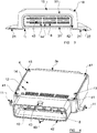
Figure 1 is a perspective view of a housing of an electronic control unit according to the present invention, showing ECU electronics located within the housing; -
Figure 2 is a perspective view of a housing of an electronic control unit according to the present invention; -
Figure 3 is a front view of an electronic control unit casing according to the present invention; -
Figure 4 is a perspective view of the housing offigure 1 , showing a printed circuit board located within the housing; -
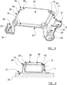
Figure 5 is a perspective view of a cover of an electronic control unit casing according to the present invention; -
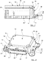
Figure 6 is a cross-sectional schematic view of an electronic control unit according to the present invention; -
Figure 7 is a cross-sectional view of an electronic control unit according to the present invention; -
Figure 8 is a perspective view of an electronic control unit casing according to the present invention, the casing including the housing offigures 1 and4 and the cover offigure 5 ; -
Figure 9 is a cross-sectional view of a part of an electronic control unit casing according to the present invention; and -
Figure 10 is a perspective view of the electronic control unit casing offigure 3 . - Considering the drawings in more detail,
Figure 1 shows ahousing 1 having abase 2 and an upstandingperipheral side wall 3. Thebase 2 is planar and substantially rectangular. In other embodiments, thebase 2 need not be planar and/or may be of another shape. - The
side wall 3 extends upwardly from thebase 2 and around the periphery of thebase 2 and is water impermeable. It is envisaged that thesidewall 3 may be formed integrally with thebase 2 as a unitary moulding of, for example, plastics material. Theside wall 3 defines an uppermostperipheral edge 4 which is located in spaced relation to thebase 2. In the particular embodiment illustrated, theside wall 3 is substantially perpendicular to the plane of thebase 2. In other embodiments, however, theside wall 3 may be at another angle to the plane of thebase 2, so as to thereby extend diagonally from the plane of thebase 2. - The
peripheral edge 4 extends around an access opening. Electronic components can be inserted through the access opening into thehousing 1. InFigure 1 , theperipheral edge 4 defines the perimeter of the access opening, but in other embodiments, the access opening may be smaller so that theperipheral edge 4 may extend around the access opening but not actually define the perimeter of the access opening. Thehousing 1 may include a portion which protrudes inwardly from theperipheral edge 4 to define an access opening spaced inwardly of theperipheral edge 4. - The
side wall 3 consists of four straight portions that meet at rounded corners to form a generally rectangular shape with rounded corners that generally matches the shape of thebase 2. There are four straight portions; afront portion 3a, two opposingside portions back portion 3d. - The
peripheral edge 4 is in spaced relation to thebase 2. In the particular embodiment illustrated, the corner regions of the peripheral edge are each spaced above thebase 2 by an equal first distance d1. As will thus be appreciated, the corner regions of theperipheral edge 4 thus all lie in a common plane which is parallel to the plane of thebase 2. However, the peripheral edge has a somewhat crenelated configuration, due to the provision of respective raisedlinear sections 3e provided centrally along eachstraight portion side wall 3. Each raised linear portion is spaced above thebase 2 by an equal second distance d2, which is slightly greater than the aforementioned first distance d1. As will therefore be appreciated, the raisedlinear portions 3e thus all lie in a common plane which is parallel to the plane of thebase 2, and which is spaced somewhat further from thebase 2 than the corner regions. - The
base 2 and theside wall 3 may be mould-formed as a unitary piece. In other embodiments, however, theside wall 3 may be formed in one or more pieces and thebase 2 may be formed as a separate piece, with thebase 2 and theside wall 3 being sealingly connected together. - The
housing 1 contains electronics, which optionally comprise one or more components.Figure 1 shows acapacitor 5 retained in a predetermined position inside thehousing 1 by agripping structure 6. Thegripping structure 6 comprises finger portions protruding from thebase 2 which are sized and positioned so as to receive and grip thecapacitor 5. The finger portions are positioned so as to retain thecapacitor 5 in thegripping structure 6 by virtue of friction between the finger portions and the surface of thecapacitor 5. The finger portions are positioned on opposite sides of thecapacitor 5. InFigure 1 , the inner surfaces of each finger portion which contact thecapacitor 5 are curved towards respective opposing finger portions so that the distance between the ends of the finger portions farthest from thebase 2 is somewhat smaller than the largest width of thecapacitor 5. The finger portions are resiliently deformable so that thecapacitor 5 can be pushed between the ends of the finger portions so as to adopt its illustrated position, whereupon thecapacitor 5 becomes clampingly positioned between the ends of the finger portions, and is urged towards thebase 2. In this way, the ends of the finger portions can provide a force towards thebase 2 to further retain thecapacitor 5 in its position in thehousing 1. Thecapacitor 5 is thus securely gripped by thefinger portions 6 as an interference fit. - In other embodiments, the finger portions may extend from the
side wall 3 or another part of thehousing 1 rather than thebase 2. - In other embodiments, only one finger portion may be provided and the
gripping structure 6 may be configured to grip the component against another part of thehousing 1, such as thebase 2 or theside wall 3. In such embodiments, the other part of thehousing 1 may act as the opposing finger portions. - In other embodiments, the gripping
structure 6 may be configured to receive another type of component and so the finger portions may be sized and positioned so as to receive a different configuration of component. - The
housing 1 offigure 1 has aconnector 7 for connecting the electronic components within thehousing 1 to electronics outside of thehousing 1. Theconnector 7 is positioned at thefront portion 3a of theside wall 3. Theconnector 7 has an array ofconnector pins 8 which each define an electrical connecting point inside thehousing 1 and a respective corresponding electrical connecting point outside of thehousing 1. The connector pins 8 provide respective electrical paths through theside wall 3 of thehousing 1 whilst maintaining the water-tight properties of theside wall 3. The connector pins 8 offigure 1 extend from the outside of thehousing 1, through theside wall 3 and into thehousing 1 from theside wall 3. The connector pins 8 extend through theside wall 3 generally perpendicular to theside wall 3. The portion of each pin inside of thehousing 1 is bent so that an end region of the pin turns upwardly to extend away from thebase 2. Outside of thehousing 1, the connector pins 8 are arranged in an array to complement a plug which can be externally connected to theconnector 7, in a manner known per se. - The
connector 7 also has a plug-locatingrim 42 extending outwardly from theside wall 3, therim 42 extending around the connector pins 8 such that the connector pins 8 are located within the rim. The plug-locatingrim 42 encloses an area of thefront portion 3a of theside wall 3 and is sealed against theside wall 3. The plug-locatingrim 42 andpins 8 are complementary to a plug to be received by the connector. More particularly, therim 42 is complementary to a recess in the plug so that the plug-locatingrim 42 may be received within the recess of the plug so as to hold the plug and connector together by an interference fit. The arrangement of therim 42 and pins is such that when therim 42 is received in the recess of the plug the connector pins 8 align with the corresponding conductive recesses in the plug. Therim 42 is generally rectangular with rounded corners, and it extends outwardly from theside wall 3 by a distance which is somewhat greater than the distance by which the connector pins 8 extend outwardly from theside wall 3, therim 42 thereby protecting the connector pins 8 from damage in the absence of a connected plug. Therim 42 may haveprotrusions 43 on its upper and lower outer surfaces which correspond to recesses in the plug, such that when the plug is engaged with the connector, the recesses grip theprotrusions 43 to further hold the plug and connector together via an interference fit. - The
connector 7 may also have stabilising or locatingprojections 40 extending from theside wall 3 between the connector pins 8, the locatingprojections 40 corresponding with cooperating locating recesses in the plug to be received. Theseprojections 40 act to locate theconnector 7 and the plug relative to one another to avoid accidental misalignment when the two are interconnected, and may also serve to maintain the plug in place and absorb forces caused by movement of the plug, preventing them from being transferred to the connector pins 8 and thereby causing damage. - The
connector 7 can be seen in more detail inFigure 3 . Thepin areas 44 are openings in the housing. Thepins 8 are then inserted through these openings from the inside of the housing. Thepins 8 may be clipped or fastened in some other manner to the inside of the housing. Thepins 8 may be part of an assembly of pins, the assembly being formed separately from the housing and then inserted through the openings from the inside of the housing. Preferably, an assembly of pins may be attached to an electronic component, such as a PCB, to be installed in the housing. Then, the assembly of pins is inserted through the openings when the electronic component is installed in the housing. - In this embodiment, the
pin areas 44 may not be sealed in a water-tight manner, so theconnector 7 may be configured so that when a plug is connected, a water-tight seal 31 is formed aroundpin areas 44 so that liquid cannot enter thehousing 1 through thepin areas 44 of the connector. - In some embodiments, the
connector 7 and thehousing 1 sidewalls are formed integrally as a single piece for example, by over moulding pins 8. This can improve the water-tightness of the casing and the ease of assembly. - The
connector 7 shown infigure 2 is formed as a single piece together with the rest of thehousing 1. The connector pins 8 are over moulded in their respective positions in theconnector 7. Constructing the connector in this manner reduces the possibility of leakage occurring through the connector because no seams are required between separately formed neighbouring components. - Other embodiments may not have a
connector 7 and may instead contain a wireless connecting means which enables electronics within thehousing 1 to communicate with electronics outside of thehousing 1. Still further embodiments may have aconnector 7 in thecover 15 rather than thehousing 1. - The
housing 1 offigure 1 also has four support posts 9. The support posts 9 are located proximal to each corner of thehousing 1 and are attached to or formed integrally with theside wall 3, on the inner side thereof. Eachsupport post 9 defines an upwardly (in the orientation illustrated infigure 1 ) directedsupport surface 9a on which a portion of a circuit board can rest inside thehousing 1. The support surfaces 9a are positioned inside of and proximal to theperipheral edge 4, at a position which is slightly below the corner regions of theperipheral edge 4. In other embodiments more or fewer than foursupports posts 9 may be provided. - The support posts 9 each have an upwardly open central bore or recess into which fastening means such as a threaded screw can be inserted and engaged. As will thus be noted, the support surfaces 9a are thus generally annular in shape, extending around the open end the respective bore or recess.
- The
housing 1 also hascutaway portions 10 at each corner of the back of thehousing 1, where a portion of theside wall 3 is recessed proximal to thebase 2. Thebase 2 also has corresponding recesses in each of its corners proximal to theback portion 3d of theside wall 3 so as to match the shape of theside wall 3 proximal to thebase 2. The presence of thecutaway portions 10 reduces the overall amount of material required to produce thehousing 1 and improves the strength of the housing. - The embodiment of the
housing 1 illustrated has two opposingguide portions 11 for interlocking with corresponding parts of a cover, in a manner which will be described in more detail hereinafter. Theguide portions 11 of the housing extend outwardly fromrespective side portions side wall 3 proximal to thebase 2. Eachguide portion 11 terminates in an upwardly turnedlip 11a which is spaced outwardly from the respective side portion of theside wall 3. - In other embodiments there may be only one
guide portion 11 in the housing. In other embodiments, guide portion(s) 11 may extend from any part of thehousing 1 and be of any convenient shape. - The
housing 1 also has internal metal traces 12 which are fixed to thehousing 1 by struts. The struts extend upwardly from thebase 2 and thetraces 12 are located at the end of the struts farthest from thebase 2. Thetraces 12 are positioned so that they will engage with cooperating contacts on a circuit board, when the circuit board is positioned on the support surfaces 9a. - The
housing 1 also contains two circuit board locating pins 13. The locating pins 13 extend upwardly from thebase 2 inside and generally adjacent theperipheral side wall 3. The two locatingpins 13 are located proximal to opposing portions of theside wall 3. Other embodiments may have only one locating pin or more than two locating pins 13. In other embodiments, locatingpins 13 may extend from theside wall 3 or another part of thehousing 1. - The
base 2,side wall 3, support posts 9, locating pins 13, struts 12, guideportions 11 and locatingrim 42 may conveniently be mould-formed as one unitary piece for simplicity of manufacture, and to ensure substantially liquid-tight cooperation. In other embodiments some or all of these parts may be formed separately and subsequently joined in a substantially liquid-tight manner, for example via a suitable adhesive. - It is to be appreciated that the
housing 1 may have various other features which are not specifically illustrated inFigure 1 . For example, as shown inFigure 2 a modified version of thehousing 1 is illustrated which comprises internalstructural supports 35 which project from thebase 2 inside of thehousing 1 and extend betweenportions side wall 3. The supports 35 form a lattice which enhances the strength of thehousing 1. -
Figure 4 shows thehousing 1 containing a circuit board, which may optionally be a printed circuit board (PCB) 14. ThePCB 14 is located proximal to the access opening. - The shape of the
PCB 14 matches the shape inside of theperipheral edge 4 so that thePCB 14 makes full use of the space available in thehousing 1. ThePCB 14 offigure 4 is thus substantially rectangular with rounded corners. Advantageously, thePCB 14 may be shaped and sized so as to match the shape and size of the access opening, thereby making use of the maximum available space in the housing. - The
PCB 14 has four circuitboard mounting holes 41, each being located proximally to a respective corner of thePCB 14. ThePCB 14 further has two locating holes sized and positioned to receive respective locating pins 13. The locating holes are thus located proximal to two opposing edges of thePCB 14. - The
PCB 14 is located on the support surfaces 9a, and the circuit board holes 41 in thePCB 14 align with the bores or recesses in the support posts 9 so that fastening means such as threaded screws can be inserted or screwed through the circuit board holes 41 and into the bores or recesses in the support posts 9. The locating pins 13 are positioned in respective locating holes in thePCB 14 so as to ensure thePCB 14 is located in its predetermined position within the housing. - The
side wall 3 projects slightly above thePCB 14, at least at its raisedlinear sections 3e, so that the whole of thePCB 14 is located inside the housing. ThePCB 14 is mounted in the housing so as to extend across the access opening for ease of assembly. In other embodiments thePCB 14 may be located elsewhere within the housing. - The
PCB 14 infigure 4 is located distal from thebase 2 so that when thehousing 1 is mounted with an orientation so that thebase 2 is at the bottom of thehousing 1, as illustrated, thePCB 14 is located at the top of thehousing 1. Other embodiments may have thePCB 14 located in a different location in thehousing 1. - The
PCB 14 is mounted so that its electrical connections are facing thebase 2. This enables thePCB 14 to be more easily connected with other components in thehousing 1 such as thecapacitor 5. - The metal traces 12 contact the
PCB 14 and allow the connection of thecapacitor 5 to thePCB 14 electronics. The inward ends of the connector pins 8 make contact with receiving contacts in thePCB 14 so that the electronics on thePCB 14 can be connected to electronics outside of the ECU via theconnector 7. The connector pins 8 are arranged so as to match the arrangement of connections on thePCB 14. - In other embodiments, the circuit board may not be printed and may have components mounted on it via wire bonds. In other embodiments, the
PCB 14 may be replaced by electrical componentry that is not located on a circuit board. -
Figure 5 shows acover 15 of an ECU casing according to the present invention. The cover will be described with reference to the orientation shown infigure 5 for ease of reference, but it will be appreciated that the absolute orientation of the components may be altered as long as the relative orientations of the components of the cover are maintained. - The
cover 15 shown infigure 5 has a generally horizontalrectangular part 16. The perimeter of therectangular part 16 has four straight portions; afront edge 51, two opposing side edges 52, 53 and aback edge 54. These straight edges meet at rounded corner edges. The cover further comprises a generallyupright wall 17 which depends from the perimeter of the rectangular part in the form of a skirt. Theupright wall 17 depends from theback edge 54, both opposing side edges 52, 53, all of the corner edges, and from end portions of thefront edge 51 proximal to each front corner. There is a gap in theupright wall 17 beneath the central region of thefront edge 51. The region inside of theupright wall 17 and beneath the rectangular part may be considered to be inside of the cover, and regions outside of theupright wall 17 and/or above the rectangular part may be considered to be outside of the cover. - A
foot portion 21 extends horizontally outwardly from each of the portions of theupright wall 17 that depend from each of the opposing side edges 52, 53 and their respective rounded corner edges. A first foot portion 21 (on the right-hand side offigure 5 as illustrated) comprises mountingholes 22 so that fastening means such as bolts can be inserted through the holes to mount thecover 15 to a surface inside a motor vehicle. The second foot portion 21 (on the left-hand side offigure 5 as illustrated) has arecess 24 rather than a hole, so that a clamping or fastening means can engage with this recess to mount the cover to the surface. - Each
foot portion 21 has a ridge on the outer edge of thefoot portion 21 which protrudes vertically upwardly from the foot portion in the manner of a lip. - Each
foot portion 21 has a respective raisedpart upright wall 17 at a position which is higher than the rest of thefoot portion 21, and which is thus closer to therectangular part 16. In thefirst foot portion 21, the raised part is formed as abridge 33 between two lower surfaces either side of the raisedpart 33. In thesecond foot portion 21, the raisedpart 34 extends outwardly from theupright wall 17 at a location higher than the rest of the foot portion, but then extends downwards and further outwards at the same height as the rest of the foot portion. Raisedparts cover 15. The raisedparts - Each raised
part slot 23 through the foot portion. Theslots 23 are proximal to respective opposing parts of the upright wall. - The
rectangular part 16 has a roof section which is formed bydiagonal walls 19 and a raisedcentral section 20. Thediagonal walls 19 slope inwardly and upwardly (away from the upright wall 17) from the perimeter of therectangular part 16. The raisedsection 20 joins the edges of thediagonal roof walls 19 farthest from the perimeter of therectangular part 16. Thus the raisedsection 20 is raised above the plane of the perimeter. - The edges between the
diagonal walls 19 and the raisedsection 20, and between thediagonal walls 19 and the perimeter of theclosure part 16 are rounded or chamfered. - In other embodiments, the roof section may be defined by walls which are perpendicular to the raised
section 20 and extend from the perimeter directly away from the mounting portion rather than diagonally. In other embodiments thediagonal walls 19 may extend from a place inwards of the perimeter. In other embodiments, some sections of thediagonal walls 19 may extend from the perimeter of therectangular part 16 and some sections of thediagonal walls 19 may extend from a place inwards of the perimeter of therectangular part 16. - In the particular embodiment illustrated in
figure 5 , therectangular part 16 has aflat corner region 18 at each corner. Theflat corner regions 18 extend inwardly from the perimeter of therectangular part 16 to form inwardly directed shoulders. Theflat corner regions 18 extend horizontally (perpendicularly to the direction in which theupright wall 17 extends from the rectangular part 16) inwardly from the corner edges of the perimeter. Theflat corner regions 18 each define a hole through thecover 15 through which a fastening means such as a threaded screw can be inserted. Proximal to theflat corner regions 18, thediagonal walls 19 extend from the inner edge of theflat corner regions 18 inwards and away from theupright wall 17 instead of extending from the perimeter of therectangular part 16. - As will become clear, the
cover 15 defines a closure part configured to engage with thehousing 1 to close the access opening, and a mounting portion configured to be mounted to a mountingsurface 27 in a vehicle. In the cover shown infigure 5 , the closure part is defined by therectangular part 16, and the mounting portion is defined by theupright wall 17 and the outwardly directedfoot portions 21. The rectangular part is configured to engage with the access opening of thehousing 1 to close the access opening. The foot portions are configured to be mounted to a mounting surface. - The mounting portion depends from the closure part by virtue of the
upright wall 17. Infigure 5 , the mounting portion depends from theback edge 54, both opposing side edges 52, 53, all of the corner edges and from end portions of thefront edge 51 proximal to each front corner of the perimeter of the rectangular part. - In other embodiments, the mounting portion may extend from only one side of the perimeter of the closure part, or from two opposing sides of the perimeter, or from all of the sides of the perimeter of the closure part. Alternatively, the mounting portion may extend only from one point on the perimeter of the
closure part 16, or from several points on one or more edges of the perimeter or from one or more corners of the perimeter. The mounting portion infigure 5 depends from the perimeter of theclosure part 16 perpendicularly to the plane of the perimeter. In other embodiments, the mounting portion may depend diagonally outwards of the perimeter of theclosure part 16. - In other embodiments, there may be only one
foot portion 21 and the foot portion orfoot portions 21 may extend from any part or parts of the mounting portion distal to theclosure part 16. - Each
foot portion 21 defines at least one contact surface facing away from theclosure part 16 that is suitable to contact a mountingsurface 27 in a vehicle on which the casing is to be mounted. - Each
foot portion 21 of thecover 15 offigure 5 has a guide portion. The guide portions are formed by theslots 23 in the foot portions, and correspond to thelips 11a ofguide portions 11 of thehousing 1 so that when thecover 15 andhousing 1 inter-engage so as to close the access opening, thelips 11 a of theguide portions 11 interlock with theslots 23. Theslots 23 have a complementary shape to thelips 11a so that thelips 11a can interlock with theslots 23. Theslots 23 are positioned so that when thelips 11a are located in the slots, thecover 15 andhousing 1 are relatively positioned so that theclosure part 16 closes the access opening. In other embodiments, the guide portions may not be formed by slots, but by some other shape complementary to a guide portion of the housing. -
Figure 6 shows thecover 15 andhousing 1 inter-engaged to close the access opening in thehousing 1. Thecover 15 is positioned over thehousing 1, such that theperipheral edge 4 of thehousing 1 engages with the perimeter of theclosure part 16 in order to close the access opening of thehousing 1. The mounting portion extends alongside the sidewall of thehousing 1 and the foot portions may be fastened to a mountingsurface 27 of a vehicle so as to mount the casing on the mountingsurface 27. - The
housing 1 and cover 15 are substantially as described above, but differences and important features are discussed further below. - The mounting portion of the embodiment shown in
figure 6 depends diagonally from the perimeter of theclosure part 16. Theside wall 3 of thehousing 1 extends diagonally upwards and outwards from the periphery of thebase 2. The perimeter of theclosure part 16 is in a plane parallel to the plane of thebase 2. Thefoot portions 21 extend away from thehousing 1 and are mounted on the mountingsurface 27 of the motor vehicle. - The mounting portion depends alongside the
side wall 3 of thehousing 1. The contact surface of thefoot portion 21 is spaced from theperipheral edge 4 of thehousing 1 by an equal or greater distance than that by which thebase 2 is spaced from theperipheral edge 4. When the casing is mounted on a mountingsurface 27, theperipheral edge 4 is spaced from the mountingsurface 27 by at least the distance by which theperipheral edge 4 is spaced from thebase 2. - In some embodiments, when inter-engaged, the
cover 15 andhousing 1 may form a water tight seal at the interface between thecover 15 and thehousing 1. This seal may be formed between theperipheral edge 4 of thehousing 1 and the perimeter of theclosure part 16 of thecover 15 by virtue of their engagement alone or by the application of a waterproof sealant material. - The interface between the
cover 15 and thehousing 1 is distal from the contact surfaces of thefoot portions 21. Thus, when the casing is mounted on a horizontal surface, the interface between thecover 15 and thehousing 1 is at the top of the casing. This means that even if the interface between thecover 15 and thehousing 1 does not form a perfect water-tight seal, any water that enters the casing, must enter at the top of the casing. Thus as long as the water level is lower than theperipheral edge 4, water cannot enter the casing even if the seal is not perfect. - In embodiments where the
housing 1 includes a portion which protrudes inwards from theperipheral edge 4 to define an access opening inside of theperipheral edge 4, theclosure part 16 may engage this portion rather than theperipheral edge 4 so as to close the access opening. In other embodiments, theclosure part 16 may engage theside wall 3 around the peripheral edge to close the access opening. - The mounting portion in
figure 6 substantially covers all of thehousing 1 except thebase 2 and theconnector 7. In other embodiments, the mounting portion may extend alongside only one portion of theside wall 3 when thecover 15 engages thehousing 1 to close the access opening, or it may extend alongside two opposing regions of theside wall 3 or all portions of theside wall 3. - As is shown in
figure 6 and infigure 7 , thewater level 28 is below the peripheral edge of the side wall of the housing. So, if water is present up to thewater level 28, water cannot enter the casing even when thehousing 1 and cover 15 are engaged loosely around the peripheral edge so as not to form a perfect water tight seal around the access opening. Thus a casing with an imperfect seal around the peripheral edge will still not allow water at the height of thewater level 28 to enter the casing. - The
water level 28 may be 20mm from the mounting surface. Thus in embodiments which are configured for awater level 28 of 20mm, the height between the contact surface of thefoot portion 21 and theperipheral edge 4 is equal to or greater than 20mm. Thus the mounting portion is configured to mount the casing to a mountingsurface 27 so that theperipheral edge 4 is spaced from the mountingsurface 27 by at least thewater level 28, which may be 20mm. - In the embodiment shown in
figure 6 , the height of the sidewalls from thebase 2 to theperipheral edge 4 is less than the height of the mounting portion from the contact surface to theclosure part 16 and so when the casing is mounted on a mountingsurface 27, thebase 2 is suspended above the mountingsurface 27. - The support posts 9 extend from the
base 2 proximal to theside wall 3 of thehousing 1. ThePCB 14 is located on the support posts 9 and thecover 15 is placed over thehousing 1 so that the perimeter of theclosure part 16 of thecover 15 engages theperipheral edge 4 of thehousing 1. Theclosure part 16 is fastened to the support posts 9 in thehousing 1, thereby clamping thePCB 14 in its position in the casing. This reduces the effects of vibrations on thePCB 14 as it is held firmly in position and cannot move. - The
PCB 14 is located proximal to the top of the housing in the orientation offigure 6 andfigure 7 . Thus, thewater level 28 is below the PCB. So, even if a small amount of water is present inside the housing, for example below the water level 28 (for example due to gaps in the connector) it will remain well below the PCB and so water-damage to the PCB is avoided. - The raised
section 20 is spaced from the access opening and thePCB 14 byroof section walls 29. This provides aheat dissipation chamber 30 between thePCB 14 and theroof section 20. The walls of the roof section of this embodiment do not extend from the perimeter of theclosure part 16, but instead from a place inwards of the perimeter on theclosure part 16. In other embodiments, all of theclosure part 16 may be made up of the roof section andfastening regions 18. In other embodiments, the raisedsection 20 may form only a small portion of theclosure part 16 and theheat dissipation chamber 30 may be located proximal to components of the electronics of the ECU that produce the most heat. - In embodiments where the
cover 15 andhousing 1 are loosely engaged, the interface between theclosure part 16 and thehousing 1 may provide ventilation to the casing. - Turning to
figure 8 , thehousing 1 offigures 1 and4 and thecover 15 offigure 5 are illustrated in an inter-engaged configuration so as to close thehousing 1. - The mounting portion of the embodiment shown in
figure 8 depends vertically from the perimeter of theclosure part 16. Theside wall 3 of thehousing 1 extends vertically upwards from the periphery of thebase 2. The perimeter of theclosure part 16 is in a plane parallel to the plane of thebase 2. - The
cover 15 andhousing 1 inter-engage in a similar manner to the embodiment offigure 6 , but differences and important features will be further discussed below. - The perimeter of the
rectangular part 16 offigure 5 is configured to engage theperipheral edge 4 of thehousing 1 offigures 1 and4 , as shown infigure 8 , in order to close thehousing 1. Thus the perimeter of therectangular part 16 is substantially the same size and shape as theperipheral edge 4 of thehousing 1 offigures 1 and4 . In other embodiments of the invention, a closure part may be configured to engage with theside wall 3 of thehousing 1 at another location or to engage with another part of thehousing 1 such as a portion extending inwards from theperipheral edge 4 to define a smaller access opening. In other embodiments, thecover 15 may have a vent aperture through the raisedsection 20. - The
flat corner regions 18 act as fastening regions. The holes in each of theflat corner regions 18 align with the holes in thePCB 14 and the bores or recesses in the support posts 9. A fastening means such as a threaded screw can be inserted through each hole in theflat corner regions 18, through the aligned and corresponding mountinghole 41 in thePCB 14 and into the aligned and corresponding bore or recess in the support posts 9 to thereby secure thecover 15 to thehousing 1, and to clamp thePCB 14 in its position in thehousing 1. Thecutaway portions 10 are located beneath the support posts 9 and thecutaway portions 10 act to improve the strength of the housing around the support posts 9, thereby preventing damage to the housing during fastening. - The inwardly directed shoulders defined by the corner regions 18a of the
cover 15 contact thePCB 14 which is located on the support posts 9, and so clamp thePCB 14 against the support posts 9 when the fastening means are in place. In other embodiments, thePCB 14 may be clamped in position by a clamping means that is separate from the fastening means or by virtue of the inter-engagement of thecover 15 andhousing 1. - The mounting portion extends outside of and alongside the
side wall 3 of thehousing 1. The mounting portion extends parallel to theside wall 3. Theconnector 7 is positioned in the gap in the front portion of the mounting portion so that the mounting portion surrounds therim 42 of theconnector 7 above and at its sides. - The
lips 11a of theguide portions 11 of thehousing 1 interlock with theslots 23 of thecover 15 to ensure that thecover 15 and thehousing 1 are relatively positioned so that theclosure part 16 closes the access opening of thehousing 1. - A means of securing the cover and housing using fastening means inserted through holes in the flat corner regions and into the bore or recess of the support posts has been described above, but it will be appreciated that alternative means of securing the cover and the housing in their relative positions are also possible.
- One such alternative is illustrated in
figure 9 which shows a snap-fit mechanism for maintaining thehousing 1 and thecover 15 in their inter-engaged configuration. Thus, fastening means such as a threaded screw andsupport posts 9 are not necessary. In general, a snap-fit mechanism comprises two snap-fit components, one on the housing and one on thecover 15. The components are positioned so that they inter-engage to retain thehousing 1 and cover 15 in their relative positions, when thehousing 1 and thecover 15 are inter-engaged to close the access opening. - In the snap-fit mechanism shown in
figure 9 , the snap-fit components are a snap-fit protrusion 37 on thehousing 1 and a snap-fit recess 38 in thecover 15. The snap-fit protrusion 37 engages the snap-fit recess 38 when thehousing 1 and thecover 15 are inter-engaged to close the access opening. The snap-fit protrusion 37 is located on the outside of theside wall 3 of thehousing 1 proximal to thebase 2 and the snap-fit recess 38 is located on the inner surface of theupright wall 17 of thecover 15. - When the
cover 15 is pushed onto thehousing 1, the snap-fit protrusion 37 and/or the housing proximal to the protrusion, is resiliently deformed to allow thecover 15 to be pushed over thehousing 1. When the snap-fit protrusion 37 aligns with the snap-fit recess 38, the snap-fit protrusion 37 and/or the housing proximal to the protrusion can return to its original shape and the snap-fit protrusion 37 engages the snap-fit recess. The snap-fit protrusion 37 may have a complementary shape to the snap-fit recess 38. - In other embodiments, the snap-
fit protrusion 37 and the snap-fit recess 38 may be located anywhere on the housing and cover as long as they are relatively positioned so that the two snap-fit components inter-engage when thehousing 1 and thecover 15 are inter-engaged to close the access opening. Further embodiments may include one or more snap-fit mechanisms and/or one or more fastening means such as a threaded screw andsupport posts 9 described earlier. -
Figure 10 shows a housing and cover where only one of thefoot portions 21 is configured to be mounted to the mountingsurface 27 by virtue of mountinghole 22. - When used in this specification and claims, the terms "comprises" and "comprising" and variations thereof mean that the specified features, steps or integers are included. The terms are not to be interpreted to exclude the presence of other features, steps or integers.
- The features disclosed in the foregoing description, or in the following claims, or in the accompanying drawings, expressed in their specific forms or in terms of a means for performing the disclosed function, or a method or process for obtaining the disclosed results, as appropriate, may, separately, or in any combination of such features, be utilised for realising the invention in diverse forms thereof.
- While the invention has been described in conjunction with the exemplary embodiments described above, many equivalent modifications and variations will be apparent to those skilled in the art when given this disclosure. Accordingly, the exemplary embodiments of the invention set forth above are considered to be illustrative and not limiting. Various changes to the described embodiments may be made without departing from the spirit and scope of the invention.
Claims (15)
- A motor vehicle electronic control unit casing comprising:a housing (1) for electronic components, and a cover (15), the housing and cover (15) being inter-engageable;the housing (1) having a base (2), and an upstanding peripheral side wall (3) defining a peripheral edge (4) in spaced relation to said base (2) and which extends around an access opening of the housing;said cover (15) having a closure part (16) and being configured to close said access opening via engagement between the closure part (16) and the housing (1) around said peripheral edge (4);said cover (15) having a mounting portion configured to be mounted to a mounting surface (27) in a motor vehicle;wherein said mounting portion depends from said closure part (16) so as to extend substantially alongside the peripheral sidewall of the housing (1) when the housing and the cover (15) are inter-engaged to close said access opening, the mounting portion thereby being configured to secure the housing relative to the mounting surface (27) such that the peripheral edge (4) is spaced from the mounting surface (27).
- A motor vehicle electronic control unit casing according to claim 1 wherein the mounting portion is configured to secure the housing (1) relative to the mounting surface (27) such that the peripheral edge (4) is spaced from the mounting surface (27) by at least the distance by which the peripheral edge (4) is spaced from the base (2).
- A motor vehicle electronic control unit casing according to claim 1 or claim 2 wherein the mounting portion is configured to secure the housing (1) relative to the mounting surface (27) such that the peripheral edge (4) is spaced from the mounting surface (27) by at least 20mm.
- A motor vehicle electronic control unit casing according to any preceding claim
wherein the closure part (16) of the cover (15) is configured to engage the housing (1) along the peripheral edge (4) of the housing, to thereby close the access opening of the housing. - A motor vehicle electronic control unit casing according to any preceding claim
wherein the housing (1) further includes a connector (7) for electrically connecting electronic components within the housing to electronics outside of the housing. - A motor vehicle electronic control unit casing according to any preceding claim
wherein when the housing (1) and the cover (15) are inter-engaged to close said access opening, the mounting portion extends substantially alongside two opposing regions of the peripheral side wall (3). - A motor vehicle electronic control unit casing according to any of claims 5 or 6
wherein when the housing (1) and the cover (15) are inter-engaged to close said access opening, the cover (15) substantially covers all of the housing except the base (2) and the connector (7). - A motor vehicle electronic control unit casing according to any preceding claim
wherein the closure part (16) has a raised section (20) such that, when the housing (1) and the cover (15) are inter-engaged to close said access opening, the raised section (20) is spaced from the access opening. - A motor vehicle electronic control unit casing according to claim 8 wherein the cover (15) has a vent aperture through the raised section (20).
- A motor vehicle electronic control unit casing according to any preceding claim
wherein the mounting portion further includes a foot portion (21) distal to the closure part (16), the foot portion (21) extending away from the housing (1) and the foot portion (21) being configured for securing the casing to the mounting surface (27). - A motor vehicle electronic control unit comprising a motor vehicle electronic control unit casing of any preceding claim, and further comprising electronic componentry located within the casing.
- A motor vehicle electronic control unit according to claim 11 wherein said componentry includes an electronic component located proximal to the access opening.
- A motor vehicle electronic control unit according to claim 12 when dependent on claim 8 wherein a heat dissipation chamber (30) is defined between said electronic component and the raised section (20).
- A motor vehicle electronic control unit according to claim 11, claim 12 or claim 13 wherein said componentry includes an electronic component which is clamped to the housing (1).
- A motor vehicle electronic control unit according to claim 14 wherein said component is clamped between the housing (1) and the cover (15) by virtue of interengagement of the housing and the cover (15).
Priority Applications (4)
| Application Number | Priority Date | Filing Date | Title |
|---|---|---|---|
| EP17194789.8A EP3468319B1 (en) | 2017-10-04 | 2017-10-04 | Electronic control unit |
| CN201880064298.9A CN111165081B (en) | 2017-10-04 | 2018-10-03 | electronic control unit |
| US16/652,635 US11026337B2 (en) | 2017-10-04 | 2018-10-03 | Electronic control unit |
| PCT/EP2018/076893 WO2019068751A1 (en) | 2017-10-04 | 2018-10-03 | Electronic control unit |
Applications Claiming Priority (1)
| Application Number | Priority Date | Filing Date | Title |
|---|---|---|---|
| EP17194789.8A EP3468319B1 (en) | 2017-10-04 | 2017-10-04 | Electronic control unit |
Publications (2)
| Publication Number | Publication Date |
|---|---|
| EP3468319A1 true EP3468319A1 (en) | 2019-04-10 |
| EP3468319B1 EP3468319B1 (en) | 2021-08-18 |
Family
ID=60019823
Family Applications (1)
| Application Number | Title | Priority Date | Filing Date |
|---|---|---|---|
| EP17194789.8A Active EP3468319B1 (en) | 2017-10-04 | 2017-10-04 | Electronic control unit |
Country Status (4)
| Country | Link |
|---|---|
| US (1) | US11026337B2 (en) |
| EP (1) | EP3468319B1 (en) |
| CN (1) | CN111165081B (en) |
| WO (1) | WO2019068751A1 (en) |
Cited By (1)
| Publication number | Priority date | Publication date | Assignee | Title |
|---|---|---|---|---|
| CN111328239A (en) * | 2020-03-18 | 2020-06-23 | 安徽国耀通信科技有限公司 | Communication cabinet with integrally replaceable shell |
Families Citing this family (9)
| Publication number | Priority date | Publication date | Assignee | Title |
|---|---|---|---|---|
| WO2020241510A1 (en) * | 2019-05-28 | 2020-12-03 | 三菱自動車工業株式会社 | Bracket for electronic control device |
| FR3111598B1 (en) * | 2020-06-23 | 2022-08-26 | Psa Automobiles Sa | Alarm support cover |
| US12247898B2 (en) * | 2020-07-02 | 2025-03-11 | Mitsubishi Electric Corporation | In-vehicle equipment and deterioration determining method |
| EP3941172B1 (en) * | 2020-07-16 | 2024-01-24 | TE Connectivity Germany GmbH | Electronic component with cooling clearance, and assembly method |
| KR102470353B1 (en) * | 2020-08-13 | 2022-11-23 | 효성중공업 주식회사 | A system for grounding a component |
| EP3975673B1 (en) * | 2020-09-28 | 2024-04-10 | Aptiv Technologies Limited | Enclosure for electronics |
| US12077110B2 (en) | 2021-06-29 | 2024-09-03 | Apple Inc. | Consolidated electronics packaging |
| US11744026B1 (en) * | 2022-08-03 | 2023-08-29 | Appleton Grp Llc | Chassis housing and support structures to secure a circuit board within the chassis housing |
| WO2024182993A1 (en) * | 2023-03-07 | 2024-09-12 | 罗伯特·博世有限公司 | Vehicle ecu unit and vehicle airbag assembly |
Citations (2)
| Publication number | Priority date | Publication date | Assignee | Title |
|---|---|---|---|---|
| DE10346990A1 (en) * | 2003-10-07 | 2005-05-04 | Conti Temic Microelectronic | Two-part housing with lower shell and upper lid for electronic unit has lower shell and an upper lid and can be attached to support by means of attachment arrangement of housing lid that reach into plane of support |
| US20160295724A1 (en) * | 2015-03-30 | 2016-10-06 | Fujitsu Ten Limited | Fixing structure |
Family Cites Families (11)
| Publication number | Priority date | Publication date | Assignee | Title |
|---|---|---|---|---|
| JP4635994B2 (en) * | 2006-09-22 | 2011-02-23 | 株式会社デンソー | Waterproof housing and electronic control device having waterproof housing |
| US8437134B2 (en) * | 2010-01-13 | 2013-05-07 | Honda Motor Co., Ltd. | Housing structure for vehicle electronic control unit |
| JP5785811B2 (en) | 2011-08-02 | 2015-09-30 | 矢崎総業株式会社 | Waterproof box and electrical junction box provided with the same |
| JP5413443B2 (en) * | 2011-12-12 | 2014-02-12 | 株式会社デンソー | Electronic equipment |
| JP2013197405A (en) * | 2012-03-21 | 2013-09-30 | Hitachi Automotive Systems Ltd | Electronic control device |
| JP6146131B2 (en) * | 2013-05-22 | 2017-06-14 | 株式会社デンソー | Electronic control unit and protective case |
| SE538701C2 (en) * | 2014-12-19 | 2016-10-25 | Autoliv Dev | Electrical unit |
| JP6129370B1 (en) | 2016-02-15 | 2017-05-17 | 三菱電機株式会社 | Waterproof electronic device unit |
| CN206341514U (en) | 2017-01-04 | 2017-07-18 | 江苏协昌电子科技股份有限公司 | A kind of integral plug-in type controller for electric vehicle |
| CN206490935U (en) | 2017-01-24 | 2017-09-12 | 江苏吉泰科电气股份有限公司 | A kind of vehicle-mounted electric machine controller of waterproof |
| JP7164966B2 (en) * | 2018-04-09 | 2022-11-02 | 株式会社デンソーテン | Electronics |
-
2017
- 2017-10-04 EP EP17194789.8A patent/EP3468319B1/en active Active
-
2018
- 2018-10-03 CN CN201880064298.9A patent/CN111165081B/en active Active
- 2018-10-03 US US16/652,635 patent/US11026337B2/en active Active
- 2018-10-03 WO PCT/EP2018/076893 patent/WO2019068751A1/en not_active Ceased
Patent Citations (2)
| Publication number | Priority date | Publication date | Assignee | Title |
|---|---|---|---|---|
| DE10346990A1 (en) * | 2003-10-07 | 2005-05-04 | Conti Temic Microelectronic | Two-part housing with lower shell and upper lid for electronic unit has lower shell and an upper lid and can be attached to support by means of attachment arrangement of housing lid that reach into plane of support |
| US20160295724A1 (en) * | 2015-03-30 | 2016-10-06 | Fujitsu Ten Limited | Fixing structure |
Cited By (1)
| Publication number | Priority date | Publication date | Assignee | Title |
|---|---|---|---|---|
| CN111328239A (en) * | 2020-03-18 | 2020-06-23 | 安徽国耀通信科技有限公司 | Communication cabinet with integrally replaceable shell |
Also Published As
| Publication number | Publication date |
|---|---|
| WO2019068751A1 (en) | 2019-04-11 |
| CN111165081A (en) | 2020-05-15 |
| US20200245480A1 (en) | 2020-07-30 |
| EP3468319B1 (en) | 2021-08-18 |
| US11026337B2 (en) | 2021-06-01 |
| CN111165081B (en) | 2023-09-22 |
Similar Documents
| Publication | Publication Date | Title |
|---|---|---|
| EP3468319B1 (en) | Electronic control unit | |
| US9781849B2 (en) | Electronic control device | |
| US9093776B2 (en) | Electronic control device | |
| US9295175B2 (en) | Seal structure for electronic control device | |
| EP2034811B1 (en) | Electronic device including printed circuit board, connector and casing | |
| US8770989B2 (en) | Electronic control device | |
| US7736158B2 (en) | Electrical junction box with a decreased height size and waterproof function | |
| JP5905800B2 (en) | Electronic controller seal structure | |
| US6757155B2 (en) | Electronic circuit board case | |
| EP2061292A1 (en) | Electronic control apparatus | |
| US8885353B2 (en) | Electrical assembly for a motor vehicle, suitable for contacting with a connector | |
| US6971888B2 (en) | Waterproof structure of electric junction box | |
| EP1799021A2 (en) | Waterproof case | |
| US10729021B1 (en) | Capped electronic control unit | |
| JP2012114052A (en) | Waterproof structure between connector and casing | |
| US20190182971A1 (en) | Electronic control device | |
| US11171472B2 (en) | Electronic controller | |
| US10212831B2 (en) | Electronic control unit | |
| EP3975673B1 (en) | Enclosure for electronics | |
| JP4966647B2 (en) | Seal structure of electrical junction box | |
| JP2017108000A (en) | Electronic equipment | |
| JPH0682884U (en) | Case | |
| KR101927120B1 (en) | Electronic control unit having inner wall | |
| CN219740942U (en) | Vehicle controller | |
| KR101856070B1 (en) | Connector assembling structure of elctronic control device |
Legal Events
| Date | Code | Title | Description |
|---|---|---|---|
| PUAI | Public reference made under article 153(3) epc to a published international application that has entered the european phase |
Free format text: ORIGINAL CODE: 0009012 |
|
| STAA | Information on the status of an ep patent application or granted ep patent |
Free format text: STATUS: THE APPLICATION HAS BEEN PUBLISHED |
|
| AK | Designated contracting states |
Kind code of ref document: A1 Designated state(s): AL AT BE BG CH CY CZ DE DK EE ES FI FR GB GR HR HU IE IS IT LI LT LU LV MC MK MT NL NO PL PT RO RS SE SI SK SM TR |
|
| AX | Request for extension of the european patent |
Extension state: BA ME |
|
| STAA | Information on the status of an ep patent application or granted ep patent |
Free format text: STATUS: REQUEST FOR EXAMINATION WAS MADE |
|
| 17P | Request for examination filed |
Effective date: 20191008 |
|
| RBV | Designated contracting states (corrected) |
Designated state(s): AL AT BE BG CH CY CZ DE DK EE ES FI FR GB GR HR HU IE IS IT LI LT LU LV MC MK MT NL NO PL PT RO RS SE SI SK SM TR |
|
| STAA | Information on the status of an ep patent application or granted ep patent |
Free format text: STATUS: EXAMINATION IS IN PROGRESS |
|
| 17Q | First examination report despatched |
Effective date: 20200630 |
|
| GRAP | Despatch of communication of intention to grant a patent |
Free format text: ORIGINAL CODE: EPIDOSNIGR1 |
|
| STAA | Information on the status of an ep patent application or granted ep patent |
Free format text: STATUS: GRANT OF PATENT IS INTENDED |
|
| INTG | Intention to grant announced |
Effective date: 20210329 |
|
| GRAS | Grant fee paid |
Free format text: ORIGINAL CODE: EPIDOSNIGR3 |
|
| GRAA | (expected) grant |
Free format text: ORIGINAL CODE: 0009210 |
|
| STAA | Information on the status of an ep patent application or granted ep patent |
Free format text: STATUS: THE PATENT HAS BEEN GRANTED |
|
| AK | Designated contracting states |
Kind code of ref document: B1 Designated state(s): AL AT BE BG CH CY CZ DE DK EE ES FI FR GB GR HR HU IE IS IT LI LT LU LV MC MK MT NL NO PL PT RO RS SE SI SK SM TR |
|
| REG | Reference to a national code |
Ref country code: GB Ref legal event code: FG4D |
|
| REG | Reference to a national code |
Ref country code: CH Ref legal event code: EP |
|
| REG | Reference to a national code |
Ref country code: DE Ref legal event code: R096 Ref document number: 602017044179 Country of ref document: DE |
|
| REG | Reference to a national code |
Ref country code: IE Ref legal event code: FG4D Ref country code: AT Ref legal event code: REF Ref document number: 1422825 Country of ref document: AT Kind code of ref document: T Effective date: 20210915 |
|
| REG | Reference to a national code |
Ref country code: LT Ref legal event code: MG9D |
|
| REG | Reference to a national code |
Ref country code: NL Ref legal event code: MP Effective date: 20210818 |
|
| REG | Reference to a national code |
Ref country code: AT Ref legal event code: MK05 Ref document number: 1422825 Country of ref document: AT Kind code of ref document: T Effective date: 20210818 |
|
| PG25 | Lapsed in a contracting state [announced via postgrant information from national office to epo] |
Ref country code: RS Free format text: LAPSE BECAUSE OF FAILURE TO SUBMIT A TRANSLATION OF THE DESCRIPTION OR TO PAY THE FEE WITHIN THE PRESCRIBED TIME-LIMIT Effective date: 20210818 Ref country code: SE Free format text: LAPSE BECAUSE OF FAILURE TO SUBMIT A TRANSLATION OF THE DESCRIPTION OR TO PAY THE FEE WITHIN THE PRESCRIBED TIME-LIMIT Effective date: 20210818 Ref country code: HR Free format text: LAPSE BECAUSE OF FAILURE TO SUBMIT A TRANSLATION OF THE DESCRIPTION OR TO PAY THE FEE WITHIN THE PRESCRIBED TIME-LIMIT Effective date: 20210818 Ref country code: LT Free format text: LAPSE BECAUSE OF FAILURE TO SUBMIT A TRANSLATION OF THE DESCRIPTION OR TO PAY THE FEE WITHIN THE PRESCRIBED TIME-LIMIT Effective date: 20210818 Ref country code: BG Free format text: LAPSE BECAUSE OF FAILURE TO SUBMIT A TRANSLATION OF THE DESCRIPTION OR TO PAY THE FEE WITHIN THE PRESCRIBED TIME-LIMIT Effective date: 20211118 Ref country code: AT Free format text: LAPSE BECAUSE OF FAILURE TO SUBMIT A TRANSLATION OF THE DESCRIPTION OR TO PAY THE FEE WITHIN THE PRESCRIBED TIME-LIMIT Effective date: 20210818 Ref country code: FI Free format text: LAPSE BECAUSE OF FAILURE TO SUBMIT A TRANSLATION OF THE DESCRIPTION OR TO PAY THE FEE WITHIN THE PRESCRIBED TIME-LIMIT Effective date: 20210818 Ref country code: ES Free format text: LAPSE BECAUSE OF FAILURE TO SUBMIT A TRANSLATION OF THE DESCRIPTION OR TO PAY THE FEE WITHIN THE PRESCRIBED TIME-LIMIT Effective date: 20210818 Ref country code: NO Free format text: LAPSE BECAUSE OF FAILURE TO SUBMIT A TRANSLATION OF THE DESCRIPTION OR TO PAY THE FEE WITHIN THE PRESCRIBED TIME-LIMIT Effective date: 20211118 Ref country code: PT Free format text: LAPSE BECAUSE OF FAILURE TO SUBMIT A TRANSLATION OF THE DESCRIPTION OR TO PAY THE FEE WITHIN THE PRESCRIBED TIME-LIMIT Effective date: 20211220 |
|
| PG25 | Lapsed in a contracting state [announced via postgrant information from national office to epo] |
Ref country code: PL Free format text: LAPSE BECAUSE OF FAILURE TO SUBMIT A TRANSLATION OF THE DESCRIPTION OR TO PAY THE FEE WITHIN THE PRESCRIBED TIME-LIMIT Effective date: 20210818 Ref country code: LV Free format text: LAPSE BECAUSE OF FAILURE TO SUBMIT A TRANSLATION OF THE DESCRIPTION OR TO PAY THE FEE WITHIN THE PRESCRIBED TIME-LIMIT Effective date: 20210818 Ref country code: GR Free format text: LAPSE BECAUSE OF FAILURE TO SUBMIT A TRANSLATION OF THE DESCRIPTION OR TO PAY THE FEE WITHIN THE PRESCRIBED TIME-LIMIT Effective date: 20211119 |
|
| PG25 | Lapsed in a contracting state [announced via postgrant information from national office to epo] |
Ref country code: NL Free format text: LAPSE BECAUSE OF FAILURE TO SUBMIT A TRANSLATION OF THE DESCRIPTION OR TO PAY THE FEE WITHIN THE PRESCRIBED TIME-LIMIT Effective date: 20210818 |
|
| PG25 | Lapsed in a contracting state [announced via postgrant information from national office to epo] |
Ref country code: DK Free format text: LAPSE BECAUSE OF FAILURE TO SUBMIT A TRANSLATION OF THE DESCRIPTION OR TO PAY THE FEE WITHIN THE PRESCRIBED TIME-LIMIT Effective date: 20210818 |
|
| REG | Reference to a national code |
Ref country code: DE Ref legal event code: R097 Ref document number: 602017044179 Country of ref document: DE |
|
| REG | Reference to a national code |
Ref country code: CH Ref legal event code: PL |
|
| PG25 | Lapsed in a contracting state [announced via postgrant information from national office to epo] |
Ref country code: SM Free format text: LAPSE BECAUSE OF FAILURE TO SUBMIT A TRANSLATION OF THE DESCRIPTION OR TO PAY THE FEE WITHIN THE PRESCRIBED TIME-LIMIT Effective date: 20210818 Ref country code: SK Free format text: LAPSE BECAUSE OF FAILURE TO SUBMIT A TRANSLATION OF THE DESCRIPTION OR TO PAY THE FEE WITHIN THE PRESCRIBED TIME-LIMIT Effective date: 20210818 Ref country code: RO Free format text: LAPSE BECAUSE OF FAILURE TO SUBMIT A TRANSLATION OF THE DESCRIPTION OR TO PAY THE FEE WITHIN THE PRESCRIBED TIME-LIMIT Effective date: 20210818 Ref country code: EE Free format text: LAPSE BECAUSE OF FAILURE TO SUBMIT A TRANSLATION OF THE DESCRIPTION OR TO PAY THE FEE WITHIN THE PRESCRIBED TIME-LIMIT Effective date: 20210818 Ref country code: CZ Free format text: LAPSE BECAUSE OF FAILURE TO SUBMIT A TRANSLATION OF THE DESCRIPTION OR TO PAY THE FEE WITHIN THE PRESCRIBED TIME-LIMIT Effective date: 20210818 Ref country code: AL Free format text: LAPSE BECAUSE OF FAILURE TO SUBMIT A TRANSLATION OF THE DESCRIPTION OR TO PAY THE FEE WITHIN THE PRESCRIBED TIME-LIMIT Effective date: 20210818 |
|
| REG | Reference to a national code |
Ref country code: BE Ref legal event code: MM Effective date: 20211031 |
|
| PLBE | No opposition filed within time limit |
Free format text: ORIGINAL CODE: 0009261 |
|
| STAA | Information on the status of an ep patent application or granted ep patent |
Free format text: STATUS: NO OPPOSITION FILED WITHIN TIME LIMIT |
|
| PG25 | Lapsed in a contracting state [announced via postgrant information from national office to epo] |
Ref country code: MC Free format text: LAPSE BECAUSE OF FAILURE TO SUBMIT A TRANSLATION OF THE DESCRIPTION OR TO PAY THE FEE WITHIN THE PRESCRIBED TIME-LIMIT Effective date: 20210818 |
|
| 26N | No opposition filed |
Effective date: 20220519 |
|
| PG25 | Lapsed in a contracting state [announced via postgrant information from national office to epo] |
Ref country code: LU Free format text: LAPSE BECAUSE OF NON-PAYMENT OF DUE FEES Effective date: 20211004 Ref country code: IT Free format text: LAPSE BECAUSE OF FAILURE TO SUBMIT A TRANSLATION OF THE DESCRIPTION OR TO PAY THE FEE WITHIN THE PRESCRIBED TIME-LIMIT Effective date: 20210818 Ref country code: BE Free format text: LAPSE BECAUSE OF NON-PAYMENT OF DUE FEES Effective date: 20211031 |
|
| PG25 | Lapsed in a contracting state [announced via postgrant information from national office to epo] |
Ref country code: SI Free format text: LAPSE BECAUSE OF FAILURE TO SUBMIT A TRANSLATION OF THE DESCRIPTION OR TO PAY THE FEE WITHIN THE PRESCRIBED TIME-LIMIT Effective date: 20210818 Ref country code: LI Free format text: LAPSE BECAUSE OF NON-PAYMENT OF DUE FEES Effective date: 20211031 Ref country code: CH Free format text: LAPSE BECAUSE OF NON-PAYMENT OF DUE FEES Effective date: 20211031 |
|
| PG25 | Lapsed in a contracting state [announced via postgrant information from national office to epo] |
Ref country code: IE Free format text: LAPSE BECAUSE OF NON-PAYMENT OF DUE FEES Effective date: 20211004 |
|
| REG | Reference to a national code |
Ref country code: DE Ref legal event code: R081 Ref document number: 602017044179 Country of ref document: DE Owner name: VEONEER SWEDEN SAFETY SYSTEMS AB, SE Free format text: FORMER OWNER: VEONEER SWEDEN AB, VARGARDA, SE Ref country code: DE Ref legal event code: R081 Ref document number: 602017044179 Country of ref document: DE Owner name: VEONEER PASSIVE CO. AB, SE Free format text: FORMER OWNER: VEONEER SWEDEN AB, VARGARDA, SE |
|
| REG | Reference to a national code |
Ref country code: GB Ref legal event code: 732E Free format text: REGISTERED BETWEEN 20230323 AND 20230329 |
|
| PG25 | Lapsed in a contracting state [announced via postgrant information from national office to epo] |
Ref country code: CY Free format text: LAPSE BECAUSE OF FAILURE TO SUBMIT A TRANSLATION OF THE DESCRIPTION OR TO PAY THE FEE WITHIN THE PRESCRIBED TIME-LIMIT Effective date: 20210818 |
|
| REG | Reference to a national code |
Ref country code: DE Ref legal event code: R081 Ref document number: 602017044179 Country of ref document: DE Owner name: VEONEER SWEDEN SAFETY SYSTEMS AB, SE Free format text: FORMER OWNER: VEONEER PASSIVE CO. AB, STOCKHOLM, SE |
|
| PG25 | Lapsed in a contracting state [announced via postgrant information from national office to epo] |
Ref country code: HU Free format text: LAPSE BECAUSE OF FAILURE TO SUBMIT A TRANSLATION OF THE DESCRIPTION OR TO PAY THE FEE WITHIN THE PRESCRIBED TIME-LIMIT; INVALID AB INITIO Effective date: 20171004 |
|
| REG | Reference to a national code |
Ref country code: GB Ref legal event code: S117 Free format text: REQUEST FILED; REQUEST FOR CORRECTION UNDER SECTION 117 FILED ON 10 JULY 2023 |
|
| REG | Reference to a national code |
Ref country code: GB Ref legal event code: S117 Free format text: CORRECTIONS ALLOWED; REQUEST FOR CORRECTION UNDER SECTION 117 FILED ON 10 JULY 2023 WAS ALLOWED ON 25 JULY 2023 |
|
| PG25 | Lapsed in a contracting state [announced via postgrant information from national office to epo] |
Ref country code: MK Free format text: LAPSE BECAUSE OF FAILURE TO SUBMIT A TRANSLATION OF THE DESCRIPTION OR TO PAY THE FEE WITHIN THE PRESCRIBED TIME-LIMIT Effective date: 20210818 |
|
| PG25 | Lapsed in a contracting state [announced via postgrant information from national office to epo] |
Ref country code: TR Free format text: LAPSE BECAUSE OF FAILURE TO SUBMIT A TRANSLATION OF THE DESCRIPTION OR TO PAY THE FEE WITHIN THE PRESCRIBED TIME-LIMIT Effective date: 20210818 |
|
| PG25 | Lapsed in a contracting state [announced via postgrant information from national office to epo] |
Ref country code: MT Free format text: LAPSE BECAUSE OF FAILURE TO SUBMIT A TRANSLATION OF THE DESCRIPTION OR TO PAY THE FEE WITHIN THE PRESCRIBED TIME-LIMIT Effective date: 20210818 |
|
| PGFP | Annual fee paid to national office [announced via postgrant information from national office to epo] |
Ref country code: DE Payment date: 20251020 Year of fee payment: 9 |
|
| PGFP | Annual fee paid to national office [announced via postgrant information from national office to epo] |
Ref country code: GB Payment date: 20251029 Year of fee payment: 9 |
|
| PGFP | Annual fee paid to national office [announced via postgrant information from national office to epo] |
Ref country code: FR Payment date: 20251024 Year of fee payment: 9 |