EP3468064B1 - Beam training sequence design method and device - Google Patents
Beam training sequence design method and device Download PDFInfo
- Publication number
- EP3468064B1 EP3468064B1 EP17818901.5A EP17818901A EP3468064B1 EP 3468064 B1 EP3468064 B1 EP 3468064B1 EP 17818901 A EP17818901 A EP 17818901A EP 3468064 B1 EP3468064 B1 EP 3468064B1
- Authority
- EP
- European Patent Office
- Prior art keywords
- sequences
- length
- beam training
- golay
- pairs
- Prior art date
- Legal status (The legal status is an assumption and is not a legal conclusion. Google has not performed a legal analysis and makes no representation as to the accuracy of the status listed.)
- Active
Links
Images


Classifications
-
- H—ELECTRICITY
- H04—ELECTRIC COMMUNICATION TECHNIQUE
- H04L—TRANSMISSION OF DIGITAL INFORMATION, e.g. TELEGRAPHIC COMMUNICATION
- H04L25/00—Baseband systems
- H04L25/02—Details ; arrangements for supplying electrical power along data transmission lines
- H04L25/0202—Channel estimation
- H04L25/024—Channel estimation channel estimation algorithms
-
- H—ELECTRICITY
- H04—ELECTRIC COMMUNICATION TECHNIQUE
- H04J—MULTIPLEX COMMUNICATION
- H04J13/00—Code division multiplex systems
- H04J13/0007—Code type
- H04J13/0011—Complementary
- H04J13/0014—Golay
-
- H—ELECTRICITY
- H04—ELECTRIC COMMUNICATION TECHNIQUE
- H04B—TRANSMISSION
- H04B7/00—Radio transmission systems, i.e. using radiation field
- H04B7/02—Diversity systems; Multi-antenna system, i.e. transmission or reception using multiple antennas
- H04B7/04—Diversity systems; Multi-antenna system, i.e. transmission or reception using multiple antennas using two or more spaced independent antennas
- H04B7/06—Diversity systems; Multi-antenna system, i.e. transmission or reception using multiple antennas using two or more spaced independent antennas at the transmitting station
- H04B7/0613—Diversity systems; Multi-antenna system, i.e. transmission or reception using multiple antennas using two or more spaced independent antennas at the transmitting station using simultaneous transmission
- H04B7/0615—Diversity systems; Multi-antenna system, i.e. transmission or reception using multiple antennas using two or more spaced independent antennas at the transmitting station using simultaneous transmission of weighted versions of same signal
- H04B7/0617—Diversity systems; Multi-antenna system, i.e. transmission or reception using multiple antennas using two or more spaced independent antennas at the transmitting station using simultaneous transmission of weighted versions of same signal for beam forming
-
- H—ELECTRICITY
- H04—ELECTRIC COMMUNICATION TECHNIQUE
- H04B—TRANSMISSION
- H04B7/00—Radio transmission systems, i.e. using radiation field
- H04B7/02—Diversity systems; Multi-antenna system, i.e. transmission or reception using multiple antennas
- H04B7/04—Diversity systems; Multi-antenna system, i.e. transmission or reception using multiple antennas using two or more spaced independent antennas
- H04B7/06—Diversity systems; Multi-antenna system, i.e. transmission or reception using multiple antennas using two or more spaced independent antennas at the transmitting station
- H04B7/0613—Diversity systems; Multi-antenna system, i.e. transmission or reception using multiple antennas using two or more spaced independent antennas at the transmitting station using simultaneous transmission
- H04B7/0615—Diversity systems; Multi-antenna system, i.e. transmission or reception using multiple antennas using two or more spaced independent antennas at the transmitting station using simultaneous transmission of weighted versions of same signal
- H04B7/0619—Diversity systems; Multi-antenna system, i.e. transmission or reception using multiple antennas using two or more spaced independent antennas at the transmitting station using simultaneous transmission of weighted versions of same signal using feedback from receiving side
- H04B7/0621—Feedback content
- H04B7/0634—Antenna weights or vector/matrix coefficients
-
- H—ELECTRICITY
- H04—ELECTRIC COMMUNICATION TECHNIQUE
- H04B—TRANSMISSION
- H04B7/00—Radio transmission systems, i.e. using radiation field
- H04B7/02—Diversity systems; Multi-antenna system, i.e. transmission or reception using multiple antennas
- H04B7/04—Diversity systems; Multi-antenna system, i.e. transmission or reception using multiple antennas using two or more spaced independent antennas
- H04B7/08—Diversity systems; Multi-antenna system, i.e. transmission or reception using multiple antennas using two or more spaced independent antennas at the receiving station
- H04B7/0837—Diversity systems; Multi-antenna system, i.e. transmission or reception using multiple antennas using two or more spaced independent antennas at the receiving station using pre-detection combining
- H04B7/0842—Weighted combining
- H04B7/0848—Joint weighting
- H04B7/0851—Joint weighting using training sequences or error signal
-
- H—ELECTRICITY
- H04—ELECTRIC COMMUNICATION TECHNIQUE
- H04L—TRANSMISSION OF DIGITAL INFORMATION, e.g. TELEGRAPHIC COMMUNICATION
- H04L25/00—Baseband systems
- H04L25/02—Details ; arrangements for supplying electrical power along data transmission lines
- H04L25/0202—Channel estimation
- H04L25/0204—Channel estimation of multiple channels
-
- H—ELECTRICITY
- H04—ELECTRIC COMMUNICATION TECHNIQUE
- H04L—TRANSMISSION OF DIGITAL INFORMATION, e.g. TELEGRAPHIC COMMUNICATION
- H04L5/00—Arrangements affording multiple use of the transmission path
- H04L5/003—Arrangements for allocating sub-channels of the transmission path
- H04L5/0048—Allocation of pilot signals, i.e. of signals known to the receiver
-
- H—ELECTRICITY
- H04—ELECTRIC COMMUNICATION TECHNIQUE
- H04L—TRANSMISSION OF DIGITAL INFORMATION, e.g. TELEGRAPHIC COMMUNICATION
- H04L25/00—Baseband systems
- H04L25/02—Details ; arrangements for supplying electrical power along data transmission lines
- H04L25/0202—Channel estimation
Definitions
- the present invention relates to the communications field, and specifically, to a beam training sequence design method and apparatus.
- one or more antennas are configured between a transmit end and a receive end.
- a beam training sequence is sent between the transmit end and the receive end for channel estimation on a communication channel between the transmit end and the receive end. Then communication performance of the communication channel is determined by using a result of the channel estimation.
- different beam training sequences are required to perform beamforming training in different communication channel scenarios (for example, different scenarios that are corresponding to different maximum delay spread of communication channels, different channel bonding quantities, and different quantities of antennas).
- an existing beam training sequence design method is applicable to very limited communication channel scenarios, and cannot satisfy various different communication channel training requirements in communications systems. As a result, the current beam training sequence design method has a limitation.
- Document EP 2 680 471 A1 provides for the construction and use of a set of Zero-Correlation-Zone (ZCZ) Concatenated Complementary Pair (CCP) sequences with zero-correlation-zone range greater than one or with zero-correlation-zone range equal to one and the sequence set size greater than two.
- Complementary pair sequences A and B are selected and, for each member of the set of ZCZ CCP sequences, sign sequences pA and pB are combined with the complementary pair sequences to form a member ZCZ CCP sequence of the set.
- a ZCZ CCP sequence modified by propagation over a communication channel may be identified by cross-correlation with ZCZ CCP sequences of the set.
- a set of sign sequences may be constructed by recursive expansion from an initial set or found by a computer search. The sequences may be used in a transceiver of a portable electronic device or other communication device.
- Document US 2010/0080266 A1 refers to a wireless communication system wherein communication devices exchange information utilizing data units that conform to a first format, wherein the first format includes a short training field (STF) spread with a first spread code and a first cover code, a method is for generating a physical layer (PHY) data unit that conforms to a second format, wherein the PHY data unit is for transmitting PHY information.
- a first portion of the PHY data unit is generated to indicate the PHY data unit conforms to the second format, wherein the first portion of the PHY data unit includes an STF spread with at least one of a second spread code different than the first spread code or a second cover code different than the first cover code.
- a second portion of the PHY data unit is generated according to the second format, wherein the second portion of the PHY data unit includes PHY information elements not specified by the first format.
- a method for beamforming training at a service and control point may comprise: transmitting training sequences to multiple user stations by using switched transmit antenna weight vectors; determining optimum transmit antenna weight vectors of the service and control point based on channel information that is fed back from each user station of the multiple user stations and related to channel condition of own link and cross links of the each user station.
- Embodiments of the present invention provide a beam training sequence design method and apparatus, so that a beam training sequence can be applied to various communication channels configured in different scenarios.
- an embodiment of the present invention provides a beam training sequence design method according to claim 1.
- an embodiment of the present invention provides a beam training sequence design apparatus, including modules configured to perform the method in the first aspect.
- an embodiment of the present invention further provides a beam training sequence design apparatus.
- the apparatus includes a memory, a processor, and N T transmit antennas.
- the memory is configured to store a program instruction
- the processor is configured to support the beam training sequence design apparatus in performing corresponding functions in the beam training sequence design method provided in the first aspect.
- the present invention provides a computer storage medium, configured to store a computer software instruction used by an apparatus provided in the third aspect.
- the computer storage medium includes a program designed to perform the foregoing aspects.
- the transmit end generates the N T beam training sequences; then the transmit end sends the N T beam training sequences to the receive end by using the N T transmit antennas at the transmit end; and after the receive end receives the N T beam training sequences, each antenna at the receive end performs channel estimation based on the N T beam training sequences, to obtain N T ⁇ 1 link channel gains.
- Each beam training sequence includes the cyclic prefix and the Golay sequence with a length of 2 ⁇ N ⁇ L.
- the N T Golay sequences are orthogonal to each other.
- N T is the quantity of antennas at the transmit end.
- L is the signal length corresponding to the maximum delay T m of the channel.
- N T is a positive integer.
- N is a positive integer.
- L is a positive integer. Therefore, a beam training sequence can be no longer restricted by a quantity of antennas, a delay spread value of a channel, and a scenario such as multi-channel bonding provided that the beam training sequence satisfies the foregoing conditions, so that the beam training sequence is applicable to different channel scenario configurations.
- Embodiments of the present invention provide a beam training sequence design method and apparatus, so that a beam training sequence can be applied to various communication channels configured in different scenarios.
- the terms “first”, “second”, “third”, and so on are intended to distinguish between different objects but do not indicate a particular order.
- the term “including” or any variant thereof is intended to cover a non-exclusive inclusion.
- a process, a method, a system, a product, or a device that includes a series of steps or units is not limited to the listed steps or units, but optionally further includes an unlisted step or unit, or optionally further includes another inherent step or unit of the process, the method, the product, or the device.
- An embodiment of the present invention provides a beam training sequence design method, including:
- the transmit end generates the beam training sequences related to the quantity of antennas, the maximum delay of the channel, and a channel bonding quantity, so that the beam training sequence design method in this embodiment of the present invention is no longer restricted by a quantity of antennas, a delay spread value of a channel, and a scenario such as multi-channel bonding, and the beam training sequence is applicable to different channel scenario configurations.
- FIG. 1 is a schematic diagram of an application scenario of a sequence-based channel estimation method according to the present invention.
- This embodiment of the present invention is applicable to channel estimation under a MIMO multi-channel condition, and also applicable to channel estimation under a single-channel condition.
- a MIMO system shown in FIG. 1 includes a transmit end and a receive end.
- the transmit end and the receive end each include two antennas.
- the transmit end includes a transmit antenna M-1T and a transmit antenna M-2T
- the receive end includes a receive antenna M-1R and a receive antenna M-2R.
- a target signal obtained after a signal sent by a transmit antenna is transmitted through a channel may be received by all the receive antennas.
- the M-1T sends a source signal
- a target signal obtained after the source signal is transmitted through the 1-1 channel may be received by the M-1R
- a target signal obtained after the source signal is transmitted through the 1-2 channel may be received by the M-2R.
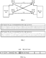
- FIG. 2 is a schematic diagram of a pair of Golay complementary sequences according to an embodiment of the present invention.
- FIG. 3-a is a schematic structural diagram of a BRP frame of a beam training sequence according to an embodiment of the present invention.
- FIG. 3-b is a schematic diagram of a beam training sequence T/R structure according to an embodiment of the present invention.
- the beam training sequence (T/R sequence) provided in this embodiment of the present invention is designed based on a beam refinement protocol (beam refinement protocol, BRP for short) frame structure used in the IEEE 802.11ad standard.
- a beam training TRN field in the BRP frame structure includes N (N ⁇ 17) TRN-Units, and each TRN-Unit is divided into two parts: CE and T/R.
- CE includes eight Golay complementary sequences with a length of 128 (Ga128 and Gb128), and cyclic prefixes and cyclic suffixes that are placed ahead of and after the Golay complementary sequences respectively, and can satisfy a multi-path channel estimation requirement in a 72 ns delay spread range.
- the T/R field includes four Golay complementary sequences with a length of 128 (Ga128 and Gb128), and cyclic prefixes placed ahead of the Golay complementary sequences, so that channel measurement may be roughly performed by using a time-domain measurement method, and accurate channel estimation may be performed in frequency domain.
- the beam training sequence can satisfy only a delay of 72 ns, and is only specific to a single-input single-output (Single Input Single Output, SISO for short) channel scenario, and no corresponding design is provided for a larger delay and a multiple-input multiple-output (Multiple Input Multiple Output, MIMO for short) channel scenario.
- This embodiment of the present invention is further designed based on the T/R sequence structure, shown in FIG. 3-b , provided by the IEEE 802.11ad standard.
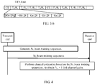
- FIG. 4 is a schematic flowchart of a first embodiment of a beam training sequence design method according to an embodiment of the present invention. As shown in FIG. 4 , the method includes the following steps.
- a transmit end generates N T beam training sequences.
- each transmit end has N T transmit antennas, and each antenna sends one beam training sequence.
- the antenna when sending the beam training sequence, the antenna sends a BRP frame that includes the beam training sequence and that is based on a BRP frame structure shown in FIG. 3-a .
- each beam training sequence includes a cyclic prefix and a Golay sequence with a length of 2 ⁇ N ⁇ L.
- the N T Golay sequences are orthogonal to each other.
- N T is a quantity of antennas at the transmit end.
- L is a signal length corresponding to a maximum delay T m of a channel.
- N T is a positive integer.
- N is a positive integer.
- L is a positive integer.
- a length of the cyclic prefix is L.
- the cyclic prefix is a Golay sequence.
- a quantity of beam training sequences is the quantity N T of antennas, and a length of the beam training sequence is the signal length corresponding to the maximum delay T m of the channel, the beam training sequence is related to a channel bonding quantity, and the beam training sequence can satisfy requirements for various quantities of antennas and different maximum delays of channels.
- the maximum delay T m of the to-be-estimated channel may be greater than or equal to 72 nanoseconds (ns), or certainly may be less than 72 ns. This is not limited herein.
- the transmit end sends the N T beam training sequences to a receive end by using N T transmit antennas at the transmit end, where each transmit antenna sends one corresponding beam training sequence.
- the receive end receives the N T channel estimation training sequence packets sent by the transmit end.
- each receive antenna receives the N T channel estimation training sequence packets, where N R is a positive integer greater than or equal to 1.
- Each receive antenna at the receive end performs channel estimation based on the N T channel estimation training sequence packets, to obtain N T ⁇ 1 link channel gains.
- each receive antenna at the receive end after receiving the N T channel estimation training sequence packets, each receive antenna at the receive end performs correlation operations by using N T correlators corresponding to the N T channel estimation training sequences, to obtain the N T ⁇ 1 link channel gains, namely, a channel estimation result.
- a complete channel estimation result of the N R receive antennas is an N R ⁇ N T channel estimation result.
- the transmit end generates the N T beam training sequences; then the transmit end sends the N T beam training sequences to the receive end by using the N T transmit antennas at the transmit end; and after the receive end receives the N T beam training sequences, each antenna at the receive end performs channel estimation based on the N T beam training sequences, to obtain the N T ⁇ 1 link channel gains.
- Each beam training sequence includes the cyclic prefix and the Golay sequence with a length of 2 ⁇ N ⁇ L.
- the N T Golay sequences are orthogonal to each other.
- N T is the quantity of antennas at the transmit end.
- L is the signal length corresponding to the maximum delay T m of the channel.
- N T is a positive integer.
- N is a positive integer.
- L is a positive integer. Therefore, a beam training sequence can be no longer restricted by a quantity of antennas, a delay spread value of a channel, and a scenario such as multi-channel bonding provided that the beam training sequence satisfies the foregoing conditions, so that the beam training sequence is applicable to different channel scenario configurations.
- the signal length L corresponding to the maximum delay T m of the channel may be understood as a length of a signal that can be transmitted based on a symbol rate of the channel under the maximum delay T m .
- a Golay sequence with a signal length related to a maximum delay of a channel is designed and used as a beam training sequence of the channel, so that the beam training sequence is applicable to different maximum delays of channels.
- channel configurations of the channel that may be applied to the designed Golay complementary sequences include any one of the following channel configurations:
- the channel bonding (Channel Bonding, CB for short) quantity is a quantity of channels bonded between the transmit end and the receive end.
- the beam training sequence can satisfy different channel delays, quantities of antennas, and channel bonding quantities, so that a communications configuration can satisfy any one of the foregoing scenarios.
- FIG. 5 is a schematic flowchart of a second embodiment of a beam training sequence design method according to an embodiment of the present invention.
- the method shown in FIG. 5 for content that is the same as or similar to content in the method shown in FIG. 4 , refer to detailed descriptions in FIG. 4 . Details are not described herein again.
- the method includes the following steps.
- a transmit end generates M pairs of Golay complementary sequences with a length of L in a preset Golay complementary sequence generation manner.
- the M pairs of Golay complementary sequences with a length of L are defined in a finite Z H field. Each pair of the M pairs of Golay complementary sequences with a length of L includes two Golay complementary sequences with a length of L. L is a signal length corresponding to a maximum delay T m of a channel. Both M and L are positive integers.
- a value is a positive integer ranging from 1 to M
- m log 2 ⁇ R s T m ⁇
- ⁇ is a value obtained after ⁇ 1, ⁇ , m ⁇ is mapped in a preset mapping manner
- c k is any value defined in the Z H field.
- a pair of Golay complementary sequences may be obtained by using the foregoing formulas:
- the Golay complementary sequences may be generated in another manner.
- the transmit end obtains N T orthogonal Golay sequences with a length of 2 ⁇ N ⁇ L based on the M pairs of Golay complementary sequences with a length of L.
- N T is a quantity of antennas at the transmit end. N T is a positive integer greater than 0. N is a positive integer greater than 0. A value of M is greater than or equal to a value of N T .
- the transmit end adds a cyclic prefix with a length of L ahead of each of the N T orthogonal Golay complementary sequences with a length of 2 ⁇ N ⁇ L, to obtain beam training sequences applied to a channel having N T antennas.
- the cyclic prefix may be a Golay sequence.
- the obtaining N T orthogonal Golay sequences with a length of 2 ⁇ N ⁇ L based on the M pairs of Golay complementary sequences with a length of L includes:
- each Golay complementary sequence with a length of L for N times in a first preset manner means adding a positive sign or a negative sign ahead of each Golay sequence with a length of L when repeatedly placing each Golay complementary sequence with a length of L, to finally obtain the N T orthogonal Golay complementary sequences with a length of 2 ⁇ N ⁇ L.
- Adding a negative sign ahead of a Golay sequence means negation of each symbol in the Golay sequence.
- Adding a positive sign ahead of a Golay sequence means keeping each symbol in the Golay sequence unchanged.
- the first preset manner of placing repeatedly and alternately the Golay complementary sequence is not unique, provided that the finally obtained N T Golay sequences with a length of 2 ⁇ N ⁇ L are orthogonal to each other.
- a value of the quantity N of times of the repeated and alternate placing is 2.
- a symbol rate of the channel is 1.76 Gbps (in this case, there is no channel aggregation, to be specific, channel bonding CB quantity is 1), and a quantity of MIMO antennas is 2, first, any two pairs of Golay complementary sequences G a1 128/G b1 128 and G a2 128/G b2 128 are obtained from the M pairs of Golay complementary sequences generated in step S201, and the two pairs of Golay complementary sequences are repeatedly and alternately placed twice separately, to obtain two sequences [-G b1 128, G a1 128, G b1 128, G a1 128] and [-G b2 128, G a2 128, G b2 128, G a2 128]; or may be repeatedly and alternately placed twice in another manner, to obtain [-G b1 128, -G a1 128, G b1 128, -G a
- the Golay complementary sequences may be repeatedly and alternately placed in a specific manner to obtain the N T orthogonal Golay sequences with a length of 2 ⁇ N ⁇ L, and then the cyclic prefix with a length of L is added ahead of each Golay sequence to obtain the beam training sequences for beam training on the channel having N T antennas, so that the beam training sequences can be no longer restricted by a quantity of antennas, a delay spread value of a channel, and a scenario such as multi-channel bonding, and is applicable to different channel scenario configurations.
- the obtaining N T orthogonal Golay sequences with a length of 2 ⁇ N ⁇ L based on the M pairs of Golay complementary sequences with a length of L includes:
- a value of N is 2, so that the preset orthogonal matrix is a 4-order orthogonal matrix.
- the placing repeatedly and alternately each pair of the ⁇ N T /2 N ⁇ pairs of Golay complementary sequences with a length of L for N times in a second preset manner may be: placing repeatedly and alternately each pair of Golay complementary sequences with a length of L among the Golay complementary sequences in any manner, to obtain ⁇ N T /2 N ⁇ Golay sequences with a length of 2 ⁇ N ⁇ L.
- the ⁇ N T /2 N ⁇ Golay sequences with a length of 2 ⁇ N ⁇ L that are obtained after the placing in the second preset manner are not necessarily orthogonal to each other.
- the preset orthogonal matrix is the 4-order orthogonal matrix. Therefore, ⁇ N T /4 ⁇ Golay sequences with a length of 2 ⁇ N ⁇ L are multiplied by the 4-order orthogonal matrix to obtain ⁇ N T /4 ⁇ ⁇ 4 orthogonal Golay sequences with a length of 2 ⁇ N ⁇ L, and then N T Golay sequences are selected from the ⁇ N T /4 ⁇ ⁇ 4 orthogonal Golay sequences with a length of 2 ⁇ N ⁇ L to obtain N T orthogonal Golay sequences with a length of 2 ⁇ N ⁇ L.
- a symbol rate of the channel is 3.52 Gbps (in this case, a channel bonding CB quantity is 2)
- a quantity of MIMO antennas is 8
- any two pairs of Golay complementary sequences G a1 256/G b1 256 and G a2 256/G b2 256 are obtained from the M pairs of Golay complementary sequences generated in step S301, and the two pairs of Golay complementary sequences are repeatedly and alternately placed twice, to obtain sequences [-G b1 256, G a1 256, G b1 256, G a1 256] and [-G b2 256, G a2 256, G b2 256, G a2 256].
- the N T orthogonal Golay complementary sequences with a length of 2 ⁇ N ⁇ L may be obtained through multiplication by the orthogonal matrix, where L is the signal length corresponding to the maximum delay T m of the channel; and the cyclic prefix with a length of L is added ahead of each Golay sequence to obtain the beam training sequences for beam training on the channel having N T antennas, so that the beam training sequence can be no longer restricted by a quantity of antennas, a delay spread value of a channel, and a scenario such as multi-channel bonding, and is applicable to different channel scenario configurations.
- the beam training sequences related to the quantity of antennas, the maximum delay of the channel, and the channel bonding quantity are generated. Therefore, a beam training sequence can be no longer restricted by a quantity of antennas, a delay spread value of a channel, and a scenario such as multi-channel bonding provided that the beam training sequence satisfies the foregoing conditions, so that the beam training sequence is applicable to different channel scenario configurations.
- FIG. 6-a is a schematic flowchart of a third embodiment of a beam training sequence design method according to an embodiment of the present invention.
- the method shown in FIG. 6-a for content that is the same as or similar to content in the method shown in FIG. 4 or FIG. 5 , refer to detailed descriptions in FIG. 4 or FIG. 5 . Details are not described herein again.
- the method includes the following steps.
- the M pairs of Golay complementary sequences with a length of L are defined in a finite Z H field. Each pair of the M pairs of Golay complementary sequences with a length of L includes two Golay complementary sequences with a length of L. L is a signal length corresponding to a maximum delay T m of a channel. Both M and L are positive integers greater than 0.
- N T is a quantity of antennas at a transmit end.
- N T is a positive integer greater than 0.
- N is a positive integer greater than 0.
- a value of M is greater than or equal to a value of N T .
- the following describes examples of the beam training sequence generation method in different channel scenarios.
- the maximum delay T m of the to-be-estimated channel is 72 ns
- a quantity N T of MIMO antennas is 2.
- FIG. 6-b is a first schematic diagram of a beam training sequence according to a third embodiment of the present invention.
- FIG. 6-b is a first schematic diagram of a beam training sequence according to an embodiment of the present invention.
- the maximum delay T m of the to-be-estimated channel is 72 ns
- a quantity N T of MIMO antennas is 8.
- the eight pairs of Golay complementary sequences are repeatedly and alternately placed twice separately, and the cyclic prefix with a length of L is added, to construct a beam training sequence E-T/R.
- the beam training sequence E-T/R may be generated based on FIG. 6-b .
- the one pair of Golay complementary sequences is repeatedly and alternately placed twice separately, and the cyclic prefix with a length of L is added, to construct a beam training sequence E-T/R.
- the beam training sequence E-T/R may be generated based on FIG. 6-b .
- the maximum delay T m of the to-be-estimated channel is 72 ns
- a quantity N T of MIMO antennas is 2.
- two pairs of Golay complementary sequences G a1 256/G b1 256 and G a2 256/G b2 256 may be generated.
- the two pairs of Golay complementary sequences are repeatedly and alternately placed twice separately, and the cyclic prefix with a length of L is added, to construct a beam training sequence E-T/R.
- the beam training sequence E-T/R may be generated based on FIG. 6-b .
- the maximum delay T m of the to-be-estimated channel is 72 ns
- a quantity N T of MIMO antennas is 4.
- Golay complementary sequences G a1 256/G b1 256, G a2 256/G b2 256, G a3 256/G b3 256, and G a4 256/G b4 256 may be generated.
- the two pairs of Golay complementary sequences are repeatedly and alternately placed twice separately, and the cyclic prefix with a length of L is added, to construct a beam training sequence E-T/R.
- the beam training sequence E-T/R may be generated based on FIG. 6-b .
- eight pairs of Golay complementary sequences G a1 256/G b1 256, G a2 256/G b2 256, G a3 256/G b3 256, G a4 256/G b4 256, G a5 256/G b5 256, G a6 256/G b6 256, G a7 256/G b7 256, and G a8 256/G b8 256 may be generated.
- the two pairs of Golay complementary sequences are repeatedly and alternately placed twice separately, and the cyclic prefix with a length of L is added, to construct a beam training sequence E-T/R.
- the beam training sequence E-T/R may be generated based on FIG. 6-b .
- the maximum delay T m of the to-be-estimated channel is 72 ns
- a quantity N T of SISO antennas is 1.
- the one pair of Golay complementary sequences is repeatedly and alternately placed twice separately, and the cyclic prefix with a length of L is added, to construct a beam training sequence E-T/R.
- the beam training sequence E-T/R may be generated based on FIG. 6-b .
- the maximum delay T m of the to-be-estimated channel is 72 ns
- a quantity N T of MIMO antennas is 2.
- two pairs of Golay complementary sequences G a1 512/G b1 512 and G a2 512/G b2 512 are generated.
- the two pairs of Golay complementary sequences are repeatedly and alternately placed twice separately, and the cyclic prefix with a length of L is added, to construct a beam training sequence E-T/R.
- the beam training sequence E-T/R may be generated based on FIG. 6-b .
- the maximum delay T m of the to-be-estimated channel is 72 ns
- a quantity N T of MIMO antennas is 4.
- Golay complementary sequences G a1 512/G b1 512, G a2 512/G b2 512, G a3 512/G b3 512, and G a4 512/G b4 512 are generated.
- the two pairs of Golay complementary sequences are repeatedly and alternately placed twice separately, and the cyclic prefix with a length of L is added, to construct a beam training sequence E-T/R.
- the beam training sequence E-T/R may be generated based on FIG. 6-b .
- the maximum delay T m of the to-be-estimated channel is 72 ns
- a quantity N T of MIMO antennas is 8.
- eight pairs of Golay complementary sequences G a1 512/G b1 512, G a2 512/G b2 512, G a3 512/G b3 512, G a4 512/G b4 512, G a5 512/G b5 512, G a6 512/G b6 512, G a7 512/G b7 512, and G a8 512/G b8 512 are generated.
- the eight pairs of Golay complementary sequences are repeatedly and alternately placed twice separately, and the cyclic prefix with a length of L is added, to construct a beam training sequence E-T/R.
- the beam training sequence E-T/R may be generated based on FIG. 6-b .
- the one pair of Golay complementary sequences is repeatedly and alternately placed twice separately, and the cyclic prefix with a length of L is added, to construct a beam training sequence E-T/R.
- the beam training sequence E-T/R may be generated based on FIG. 6-b .
- the maximum delay T m of the to-be-estimated channel is 300 ns
- a quantity N T of MIMO antennas is 2.
- two pairs of Golay complementary sequences G a1 512/G b1 512 and G a2 512/G b2 512 are generated.
- the two pairs of Golay complementary sequences are repeatedly and alternately placed twice separately, and the cyclic prefix with a length of L is added, to construct a beam training sequence E-T/R.
- the beam training sequence E-T/R may be generated based on FIG. 6-b .
- the maximum delay T m of the to-be-estimated channel is 300 ns
- a quantity N T of MIMO antennas is 4.
- Golay complementary sequences G a1 512/G b1 512, G a2 512/G b2 512, G a3 512/G b3 512, and G a4 512/G b4 512 are generated.
- the beam training sequence E-T/R may be generated based on FIG. 6-b .
- the maximum delay T m of the to-be-estimated channel is 300 ns
- a quantity N T of MIMO antennas is 8.
- eight pairs of Golay complementary sequences G a1 512/G b1 512, G a2 512/G b2 512, G a3 512/G b3 512, G a4 512/G b4 512, G a5 512/G b5 512, G a6 512/G b6 512, G a7 512/G b7 512, and G a8 512/G b8 512 are generated.
- the eight pairs of Golay complementary sequences are repeatedly and alternately placed twice separately, and the cyclic prefix with a length of L is added, to construct a beam training sequence E-T/R.
- the beam training sequence E-T/R may be generated based on FIG. 6-b .
- the maximum delay T m of the to-be-estimated channel is 300 ns
- a quantity N T of SISO antennas is 1.
- the one pair of Golay complementary sequences is repeatedly and alternately placed twice separately, and the cyclic prefix with a length of L is added, to construct a beam training sequence E-T/R.
- the beam training sequence E-T/R may be generated based on FIG. 6-b .
- the maximum delay T m of the to-be-estimated channel is 300 ns
- a quantity N T of MIMO antennas is 2.
- the two pairs of Golay complementary sequences are repeatedly and alternately placed twice separately, and the cyclic prefix with a length of L is added, to construct a beam training sequence E-T/R.
- the beam training sequence E-T/R may be generated based on FIG. 6-b .
- the maximum delay T m of the to-be-estimated channel is 300 ns
- a quantity N T of MIMO antennas is 4.
- the beam training sequence E-T/R may be generated based on FIG. 6-b .
- the maximum delay T m of the to-be-estimated channel is 300 ns
- a quantity N T of MIMO antennas is 8.
- eight pairs of Golay complementary sequences G a1 1024/G b1 1024, G a2 1024/G b2 1024, G a3 1024/G b3 1024, G a4 1024/G b4 1024, G a5 1024/G b5 1024, G a6 1024/G b6 1024, G a7 1024/G b7 1024, and G a8 1024/G b8 1024 are generated.
- the eight pairs of Golay complementary sequences are repeatedly and alternately placed twice separately, and the cyclic prefix with a length of L is added, to construct a beam training sequence E-T/R.
- the beam training sequence E-T/R may be generated based on FIG. 6-b .
- the maximum delay T m of the to-be-estimated channel is 300 ns
- a quantity N T of SISO antennas is 1.
- the one pair of Golay complementary sequences is repeatedly and alternately placed twice separately, and the cyclic prefix with a length of L is added, to construct a beam training sequence E-T/R.
- the beam training sequence E-T/R may be generated based on FIG. 6-b .
- the maximum delay T m of the to-be-estimated channel is 300 ns
- a quantity N T of MIMO antennas is 2.
- the two pairs of Golay complementary sequences are repeatedly and alternately placed twice separately, and the cyclic prefix with a length of L is added, to construct a beam training sequence E-T/R.
- the beam training sequence E-T/R may be generated based on FIG. 6-b .
- the maximum delay T m of the to-be-estimated channel is 300 ns
- a quantity N T of MIMO antennas is 4.
- the beam training sequence E-T/R may be generated based on FIG. 6-b .
- the maximum delay T m of the to-be-estimated channel is 300 ns
- a quantity N T of MIMO antennas is 8.
- eight pairs of Golay complementary sequences G a1 2048/G b1 2048, G a2 2048/G b2 2048, G a3 2048/G b3 2048, G a4 2048/G b4 2048, G a5 2048/G b5 2048, G a6 2048/G b6 2048, G a7 2048/G b7 2048, and G a8 2048/G b8 2048 are generated.
- the eight pairs of Golay complementary sequences are repeatedly and alternately placed twice separately, and the cyclic prefix with a length of L is added, to construct a beam training sequence E-T/R.
- the beam training sequence E-T/R may be generated based on FIG. 6-b .
- the Golay complementary sequences may be repeatedly and alternately placed in a specific manner to obtain the N T orthogonal Golay sequences with a length of 2 ⁇ N ⁇ L, and then the cyclic prefix with a length of L is added ahead of each Golay sequence to obtain the beam training sequences for beam training on the channel having N T antennas, so that the beam training sequences can be no longer restricted by a quantity of antennas, a delay spread value of a channel, and a scenario such as multi-channel bonding, and is applicable to different channel scenario configurations.
- FIG. 7-a is a schematic flowchart of a fourth embodiment of a beam training sequence design method according to an embodiment of the present invention.
- the method shown in FIG. 7-a for content that is the same as or similar to content in the method shown in FIG. 4 , FIG. 5 , or FIG. 6-a , refer to detailed descriptions in FIG. 4 , FIG. 5 , or FIG. 6-a . Details are not described herein again.
- the method includes the following steps.
- the M pairs of Golay complementary sequences with a length of L are defined in a finite Z H field. Each pair of the M pairs of Golay complementary sequences with a length of L includes two Golay complementary sequences with a length of L. L is a signal length corresponding to a maximum delay T m of a channel. Both M and L are positive integers greater than 0.
- N T is a quantity of antennas at a transmit end.
- N T is a positive integer greater than 0.
- N is a positive integer greater than 0.
- a value of M is greater than or equal to a value of N T .
- a value of N is 2, so that the preset orthogonal matrix is a 4-order orthogonal matrix.
- the maximum delay T m of the to-be-estimated channel is 72 ns
- a quantity N T of MIMO antennas is 2.
- FIG. 7-c is a third schematic diagram of a beam training sequence according to an embodiment of the present invention.
- FIG. 7-d is a fourth schematic diagram of a beam training sequence according to an embodiment of the present invention.
- the maximum delay T m of the to-be-estimated channel is 72 ns
- a quantity N T of MIMO antennas is 8.
- FIG. 7-e is a fifth schematic diagram of a beam training sequence according to an embodiment of the present invention.
- FIG. 7-b is a second schematic diagram of a beam training sequence according to an embodiment of the present invention.
- the maximum delay T m of the to-be-estimated channel is 72 ns
- a quantity N T of MIMO antennas is 2.
- any two sequences are selected from the orthogonal sequences, and the cyclic prefix with a length of L is added, to construct a beam training sequence E-T/R.
- the beam training sequence E-T/R may be generated based on FIG. 7-c .
- the maximum delay T m of the to-be-estimated channel is 72 ns
- a quantity N T of MIMO antennas is 4.
- the beam training sequence E-T/R may be generated based on FIG. 7-d .
- two pairs of Golay complementary sequences G a1 256/G b1 256 and G a2 256/G b2 256 may be generated.
- Eight sequences are selected from the orthogonal sequences, and the cyclic prefix with a length of L is added, to construct a beam training sequence E-T/R.
- the beam training sequence E-T/R may be generated based on FIG. 7-e .
- the maximum delay T m of the to-be-estimated channel is 72 ns
- a quantity N T of SISO antennas is 1.
- any one sequence is selected from the orthogonal sequences, and the cyclic prefix with a length of L is added, to construct a beam training sequence E-T/R.
- the beam training sequence E-T/R may be generated based on FIG. 7-b .
- the maximum delay T m of the to-be-estimated channel is 72 ns
- a quantity N T of MIMO antennas is 2.
- any two sequences are selected from the orthogonal sequences, and the cyclic prefix with a length of L is added, to construct a beam training sequence E-T/R.
- the beam training sequence E-T/R may be generated based on FIG. 7-c .
- the maximum delay T m of the to-be-estimated channel is 72 ns
- a quantity N T of MIMO antennas is 4.
- any four sequences are selected from the orthogonal sequences, and the cyclic prefix with a length of L is added, to construct a beam training sequence E-T/R.
- the beam training sequence E-T/R may be generated based on FIG. 7-d .
- the maximum delay T m of the to-be-estimated channel is 72 ns
- a quantity N T of MIMO antennas is 8.
- two pairs of Golay complementary sequences G a1 512/G b1 512 and G a2 512/G b2 512 are generated.
- the beam training sequence E-T/R may be generated based on FIG. 7-e .
- any one sequence is selected from the orthogonal sequences, and the cyclic prefix with a length of L is added, to construct a beam training sequence E-T/R.
- the beam training sequence E-T/R may be generated based on FIG. 7-b .
- the maximum delay T m of the to-be-estimated channel is 300 ns
- a quantity N T of MIMO antennas is 2.
- any two sequences are selected from the orthogonal sequences, and the cyclic prefix with a length of L is added, to construct a beam training sequence E-T/R.
- the beam training sequence E-T/R may be generated based on FIG. 7-c .
- the maximum delay T m of the to-be-estimated channel is 300 ns
- a quantity N T of MIMO antennas is 4.
- the beam training sequence E-T/R may be generated based on FIG. 7-d .
- the maximum delay T m of the to-be-estimated channel is 300 ns
- a quantity N T of MIMO antennas is 8.
- two pairs of Golay complementary sequences G a1 512/G b1 512 and G a2 512/G b2 512 are generated.
- the beam training sequence E-T/R may be generated based on FIG. 7-e .
- the maximum delay T m of the to-be-estimated channel is 300 ns
- a quantity N T of SISO antennas is 1.
- any one sequence is selected from the orthogonal sequences, and the cyclic prefix with a length of L is added, to construct a beam training sequence E-T/R.
- the beam training sequence E-T/R may be generated based on FIG. 7-b .
- the maximum delay T m of the to-be-estimated channel is 300 ns
- a quantity N T of MIMO antennas is 2.
- any two sequences are selected from the orthogonal sequences, and the cyclic prefix with a length of L is added, to construct a beam training sequence E-T/R.
- the beam training sequence E-T/R may be generated based on FIG. 7-c .
- the maximum delay T m of the to-be-estimated channel is 300 ns
- a quantity N T of MIMO antennas is 4.
- the beam training sequence E-T/R may be generated based on FIG. 7-d .
- the maximum delay T m of the to-be-estimated channel is 300 ns
- a quantity N T of MIMO antennas is 8.
- the beam training sequence E-T/R may be generated based on FIG. 7-e .
- the maximum delay T m of the to-be-estimated channel is 300 ns
- a quantity N T of SISO antennas is 1.
- any one sequence is selected from the orthogonal sequences, and the cyclic prefix with a length of L is added, to construct a beam training sequence E-T/R.
- the beam training sequence E-T/R may be generated based on FIG. 7-b .
- the maximum delay T m of the to-be-estimated channel is 300 ns
- a quantity N T of MIMO antennas is 2.
- any one sequence is selected from the orthogonal sequences, and the cyclic prefix with a length of L is added, to construct a beam training sequence E-T/R.
- the beam training sequence E-T/R may be generated based on FIG. 7-c .
- the maximum delay T m of the to-be-estimated channel is 300 ns
- a quantity N T of MIMO antennas is 4.
- the beam training sequence E-T/R may be generated based on FIG. 7-d .
- the maximum delay T m of the to-be-estimated channel is 300 ns
- a quantity N T of MIMO antennas is 8.
- the beam training sequence E-T/R may be generated based on FIG. 7-e .
- the N T orthogonal Golay complementary sequences with a length of 2 ⁇ N ⁇ L may be obtained through multiplication by the orthogonal matrix, where L is the signal length corresponding to the maximum delay T m of the channel; and the cyclic prefix with a length of L is added ahead of each Golay sequence to obtain the beam training sequences for beam training on the channel having N T antennas, so that the beam training sequence can be no longer restricted by a quantity of antennas, a delay spread value of a channel, and a scenario such as multi-channel bonding, and is applicable to different channel scenario configurations.
- FIG. 8 is a schematic structural diagram of a first embodiment of a beam training sequence design apparatus according to an embodiment of the present invention.
- the apparatus may be integrated in the foregoing transmit-end device.
- the apparatus may include a generation module 801 and a sending module 802.
- the sending module 802 may send a signal by using N T transmit antennas of the apparatus. Details are as follows.
- the generation module 801 is configured to generate N T beam training sequences, where each beam training sequence includes a cyclic prefix and a Golay sequence with a length of 2 ⁇ N ⁇ L, the N T Golay sequences are orthogonal to each other, N T is a quantity of antennas at a transmit end, L is a signal length corresponding to a maximum delay T m of a channel, N T is a positive integer, N is a positive integer, L is a positive integer, and a length of the cyclic prefix is L; and the sending module 802 is configured to send the N T beam training sequences to a receive end by using the N T transmit antennas at the transmit end, where each transmit antenna sends one corresponding beam training sequence.
- the generation module 801 is specifically configured to:
- the generation module 801 is specifically configured to:
- the generation module 801 is specifically configured to:
- channel configurations of the channel include any one of the following channel configurations:
- the cyclic prefix is a Golay sequence.
- the generation module 801 generates the N T beam training sequences; then the sending module 802 sends the N T beam training sequences to the receive end by using the N T transmit antennas at the transmit end; and after the receive end receives the N T beam training sequences, each antenna at the receive end performs channel estimation based on the N T beam training sequences, to obtain N T ⁇ 1 link channel gains.
- Each beam training sequence includes the cyclic prefix and the Golay sequence with a length of 2 ⁇ N ⁇ L.
- the N T Golay sequences are orthogonal to each other.
- N T is the quantity of antennas at the transmit end.
- L is the signal length corresponding to the maximum delay T m of the channel.
- N T is a positive integer.
- N is a positive integer.
- L is a positive integer. Therefore, a beam training sequence can be no longer restricted by a quantity of antennas, a delay spread value of a channel, and a scenario such as multi-channel bonding provided that the beam training sequence satisfies the foregoing conditions, so that the beam training sequence is applicable to different channel scenario configurations.
- the apparatus is configured to perform the foregoing method embodiments.
- An implementation principle of the apparatus is similar to that of the method embodiments. Details are not described herein again.
- FIG. 9 is a schematic structural diagram of a second embodiment of a beam training sequence design apparatus according to an embodiment of the present invention.
- the apparatus may be integrated in the foregoing transmit-end device.
- the apparatus may include: a memory 901, a processor 902, and N T transmit antennas 903 (a transmit antenna block in FIG. 9 represents the N T transmit antennas).
- the memory 901, the processor 902, and the N T transmit antennas 903 may be coupled together by using a bus 904, but this is not construed as a limitation.
- the bus 904 may further include a power supply bus, a control bus, a status signal bus, and the like, which are collectively referred to as the bus in this embodiment.
- the memory 901 is configured to store a program instruction.
- the processor 902 is configured to invoke the program instruction stored in the memory 901 to perform the following method:
- the processor 902 is specifically configured to:
- processor 902 is specifically configured to:
- processor 902 is specifically configured to:
- channel configurations of the channel include any one of the following channel configurations:
- the cyclic prefix is a Golay sequence.
- the beam training sequence design apparatus 900 generates the N T beam training sequences, and then sends the N T beam training sequences to the receive end by using the N T transmit antennas at the transmit end; and after the receive end receives the N T beam training sequences, each antenna at the receive end performs channel estimation based on the N T beam training sequences, to obtain N T ⁇ 1 link channel gains.
- Each beam training sequence includes the cyclic prefix and the Golay sequence with a length of 2 ⁇ N ⁇ L.
- the N T Golay sequences are orthogonal to each other.
- N T is the quantity of antennas at the transmit end.
- L is the signal length corresponding to the maximum delay T m of the channel.
- N T is a positive integer.
- N is a positive integer.
- L is a positive integer. Therefore, a beam training sequence can be no longer restricted by a quantity of antennas, a delay spread value of a channel, and a scenario such as multi-channel bonding provided that the beam training sequence satisfies the foregoing conditions, so that the beam training sequence is applicable to different channel scenario configurations.
- the apparatus is configured to perform the foregoing method embodiments.
- An implementation principle of the apparatus is similar to that of the method embodiments. Details are not described herein again.
- An embodiment of the present invention further provides a computer storage medium.
- the computer storage medium may store a program. When the program is executed, some or all of the steps of any beam training sequence design method described in the foregoing method embodiments are performed.
- the disclosed apparatus may be implemented in other manners.
- the described apparatus embodiment is merely an example.
- the unit division is merely logical function division and may be other division in actual implementation.
- a plurality of units or components may be combined or integrated into another system, or some features may be ignored or not be performed.
- the shown or discussed mutual couplings or direct couplings or communication connections may be implemented through some interfaces.
- the indirect couplings or communication connections between the apparatuses or units may be implemented in electrical or other forms.
- the units described as separate parts may or may not be physically separated, and parts shown as units may or may not be physical units, may be located in one location, or may be distributed on a plurality of network units. Some or all of the units may be selected depending on actual requirements to achieve the objectives of the solutions of the embodiments.
- function units in the embodiments of the present invention may be integrated into one processing unit, or each of the units may exist alone physically, or two or more units may be integrated into one unit.
- the integrated unit may be implemented in a form of hardware, or may be implemented in a form of a software function unit.
- the integrated unit When the integrated unit is implemented in the form of a software function unit and sold or used as an independent product, the integrated unit may be stored in a computer-readable storage medium.
- the computer software product is stored in a storage medium and includes several instructions for instructing a computer device (which may be a personal computer, a server, a network device, or the like) to perform all or some of the steps of the methods described in the embodiments of the present invention.
- the storage medium includes any medium that can store program code, such as a USB flash drive, a read-only memory (ROM, Read-Only Memory), a random access memory (RAM, Random Access Memory), a removable hard disk, a magnetic disk, or an optical disc.
Landscapes
- Engineering & Computer Science (AREA)
- Signal Processing (AREA)
- Computer Networks & Wireless Communication (AREA)
- Power Engineering (AREA)
- Physics & Mathematics (AREA)
- Mathematical Physics (AREA)
- Radio Transmission System (AREA)
- Mobile Radio Communication Systems (AREA)
Description
- The present invention relates to the communications field, and specifically, to a beam training sequence design method and apparatus.
- In beamforming training, one or more antennas are configured between a transmit end and a receive end. A beam training sequence is sent between the transmit end and the receive end for channel estimation on a communication channel between the transmit end and the receive end. Then communication performance of the communication channel is determined by using a result of the channel estimation.
- In the beamforming training, different beam training sequences are required to perform beamforming training in different communication channel scenarios (for example, different scenarios that are corresponding to different maximum delay spread of communication channels, different channel bonding quantities, and different quantities of antennas). However, an existing beam training sequence design method is applicable to very limited communication channel scenarios, and cannot satisfy various different communication channel training requirements in communications systems. As a result, the current beam training sequence design method has a limitation.
- Document
EP 2 680 471 A1 provides for the construction and use of a set of Zero-Correlation-Zone (ZCZ) Concatenated Complementary Pair (CCP) sequences with zero-correlation-zone range greater than one or with zero-correlation-zone range equal to one and the sequence set size greater than two. Complementary pair sequences A and B are selected and, for each member of the set of ZCZ CCP sequences, sign sequences pA and pB are combined with the complementary pair sequences to form a member ZCZ CCP sequence of the set. A ZCZ CCP sequence modified by propagation over a communication channel may be identified by cross-correlation with ZCZ CCP sequences of the set. A set of sign sequences may be constructed by recursive expansion from an initial set or found by a computer search. The sequences may be used in a transceiver of a portable electronic device or other communication device. - Document
US 2010/0080266 A1 refers to a wireless communication system wherein communication devices exchange information utilizing data units that conform to a first format, wherein the first format includes a short training field (STF) spread with a first spread code and a first cover code, a method is for generating a physical layer (PHY) data unit that conforms to a second format, wherein the PHY data unit is for transmitting PHY information. A first portion of the PHY data unit is generated to indicate the PHY data unit conforms to the second format, wherein the first portion of the PHY data unit includes an STF spread with at least one of a second spread code different than the first spread code or a second cover code different than the first cover code. A second portion of the PHY data unit is generated according to the second format, wherein the second portion of the PHY data unit includes PHY information elements not specified by the first format. - Document
US 2012/0106474 A1 provides methods and apparatuses for beamforming training at a service and control point and a user station, and a system for beamforming training for a wireless communication system. Accordingly, a method for beamforming training at a service and control point may comprise: transmitting training sequences to multiple user stations by using switched transmit antenna weight vectors; determining optimum transmit antenna weight vectors of the service and control point based on channel information that is fed back from each user station of the multiple user stations and related to channel condition of own link and cross links of the each user station. Thus, there is provided a spatial-reuse based simultaneous beamforming training technology, which may satisfy the demands of a dense-user application; moreover, has a high spectrum efficiency and saves beamforming training time. - The invention is defined by the independent claims. Advantageous embodiments are described in the dependent claims. While several embodiments and/or examples are disclosed in this description, the subject matter for which protection is sought is strictly and solely limited to those embodiments and/ or examples encompassed by the scope of the appended claims. Embodiments and/or examples mentioned in the description that do not fall under the scope of the claims are useful for understanding the invention.
- Embodiments of the present invention provide a beam training sequence design method and apparatus, so that a beam training sequence can be applied to various communication channels configured in different scenarios.
- According to a first aspect, an embodiment of the present invention provides a beam training sequence design method according to
claim 1. - According to a second aspect, an embodiment of the present invention provides a beam training sequence design apparatus, including modules configured to perform the method in the first aspect.
- According to a third aspect, an embodiment of the present invention further provides a beam training sequence design apparatus. The apparatus includes a memory, a processor, and NT transmit antennas. The memory is configured to store a program instruction, and the processor is configured to support the beam training sequence design apparatus in performing corresponding functions in the beam training sequence design method provided in the first aspect.
- According to a fourth aspect, the present invention provides a computer storage medium, configured to store a computer software instruction used by an apparatus provided in the third aspect. The computer storage medium includes a program designed to perform the foregoing aspects.
- It can be learned that, in the technical solutions provided in the embodiments of the present invention, the transmit end generates the NT beam training sequences; then the transmit end sends the NT beam training sequences to the receive end by using the NT transmit antennas at the transmit end; and after the receive end receives the NT beam training sequences, each antenna at the receive end performs channel estimation based on the NT beam training sequences, to obtain NT × 1 link channel gains. Each beam training sequence includes the cyclic prefix and the Golay sequence with a length of 2 × N × L. The NT Golay sequences are orthogonal to each other. NT is the quantity of antennas at the transmit end. L is the signal length corresponding to the maximum delay Tm of the channel. NT is a positive integer. N is a positive integer. L is a positive integer. Therefore, a beam training sequence can be no longer restricted by a quantity of antennas, a delay spread value of a channel, and a scenario such as multi-channel bonding provided that the beam training sequence satisfies the foregoing conditions, so that the beam training sequence is applicable to different channel scenario configurations.
- To describe the technical solutions in the embodiments of the present invention art more clearly, the following briefly describes the accompanying drawings required for describing the embodiments. Apparently, the accompanying drawings in the following description show merely some embodiments of the present invention, and persons of ordinary skill in the art may still derive other drawings from these accompanying drawings without creative efforts.
-
FIG. 1 is a schematic diagram of an application scenario of a sequence-based channel estimation method according to the present invention; -
FIG. 2 is a schematic diagram of a pair of Golay complementary sequences according to an embodiment of the present invention; -
FIG. 3-a is a schematic structural diagram of a BRP frame of a beam training sequence according to an embodiment of the present invention; -
FIG. 3-b is a schematic diagram of a beam training sequence T/R structure according to an embodiment of the present invention; -
FIG. 4 is a schematic flowchart of a first embodiment of a beam training sequence design method according to an embodiment of the present invention; -
FIG. 5 is a schematic flowchart of a second embodiment of a beam training sequence design method according to an embodiment of the present invention; -
FIG. 6-a is a schematic flowchart of a third embodiment of a beam training sequence design method according to an embodiment of the present invention; -
FIG. 6-b is a first schematic diagram of a beam training sequence according to an embodiment of the present invention; -
FIG. 7-a is a schematic flowchart of a fourth embodiment of a beam training sequence design method according to an embodiment of the present invention; -
FIG. 7-b is a second schematic diagram of a beam training sequence according to an embodiment of the present invention; -
FIG. 7-c is a third schematic diagram of a beam training sequence according to an embodiment of the present invention; -
FIG. 7-d is a fouth schematic diagram of a beam training sequence according to an embodiment of the present invention; -
FIG. 7-e is a fifth schematic diagram of a beam training sequence according to an embodiment of the present invention; -
FIG. 8 is a schematic structural diagram of a first embodiment of a beam training sequence design apparatus according to an embodiment of the present invention; and -
FIG. 9 is a schematic structural diagram of a second embodiment of a beam training sequence design apparatus according to an embodiment of the present invention. - Embodiments of the present invention provide a beam training sequence design method and apparatus, so that a beam training sequence can be applied to various communication channels configured in different scenarios.
- To make persons skilled in the art understand the technical solutions in the present invention better, the following clearly describes the technical solutions in the embodiments of the present invention with reference to the accompanying drawings in the embodiments of the present invention. Apparently, the described embodiments are merely some but not all of the embodiments of the present invention. All other embodiments obtained by persons of ordinary skill in the art based on the embodiments of the present invention without creative efforts shall fall within the protection scope of the present invention.
- In the specification, claims, and accompanying drawings of the present invention, the terms "first", "second", "third", and so on are intended to distinguish between different objects but do not indicate a particular order. In addition, the term "including" or any variant thereof is intended to cover a non-exclusive inclusion. For example, a process, a method, a system, a product, or a device that includes a series of steps or units is not limited to the listed steps or units, but optionally further includes an unlisted step or unit, or optionally further includes another inherent step or unit of the process, the method, the product, or the device.
- An embodiment of the present invention provides a beam training sequence design method, including:
- generating, by a transmit end, NT beam training sequences, where each beam training sequence includes a cyclic prefix and a Golay sequence with a length of 2 × N × L, the NT Golay sequences are orthogonal to each other, NT is a quantity of antennas at the transmit end, L is a signal length corresponding to a maximum delay Tm of a channel, NT is a positive integer, N is a positive integer, and L is a positive integer; and
- sending, by the transmit end, the NT beam training sequences to a receive end by using the NT transmit antennas at the transmit end, where each transmit antenna sends one corresponding beam training sequence.
- In this embodiment of the present invention, the transmit end generates the beam training sequences related to the quantity of antennas, the maximum delay of the channel, and a channel bonding quantity, so that the beam training sequence design method in this embodiment of the present invention is no longer restricted by a quantity of antennas, a delay spread value of a channel, and a scenario such as multi-channel bonding, and the beam training sequence is applicable to different channel scenario configurations.
- First,
FIG. 1 is a schematic diagram of an application scenario of a sequence-based channel estimation method according to the present invention. This embodiment of the present invention is applicable to channel estimation under a MIMO multi-channel condition, and also applicable to channel estimation under a single-channel condition. - A MIMO system shown in
FIG. 1 includes a transmit end and a receive end. For example, the transmit end and the receive end each include two antennas. Referring toFIG. 1-a , the transmit end includes a transmit antenna M-1T and a transmit antenna M-2T, and the receive end includes a receive antenna M-1R and a receive antenna M-2R. - There are a total of four channels between the two transmit antennas and the two receive antennas: 1-1 (a channel between the M-1T and the M-1R), 1-2 (a channel between the M-1T and the M-2R), 2-1 (a channel between the M-2T and the M-1R), and 2-2 (a channel between the M-2T and the M-2R).
- In the MIMO system, a target signal obtained after a signal sent by a transmit antenna is transmitted through a channel may be received by all the receive antennas. For example, the M-1T sends a source signal, a target signal obtained after the source signal is transmitted through the 1-1 channel may be received by the M-1R, and a target signal obtained after the source signal is transmitted through the 1-2 channel may be received by the M-2R.
-
FIG. 2 is a schematic diagram of a pair of Golay complementary sequences according to an embodiment of the present invention.FIG. 3-a is a schematic structural diagram of a BRP frame of a beam training sequence according to an embodiment of the present invention.FIG. 3-b is a schematic diagram of a beam training sequence T/R structure according to an embodiment of the present invention. - The beam training sequence (T/R sequence) provided in this embodiment of the present invention is designed based on a beam refinement protocol (beam refinement protocol, BRP for short) frame structure used in the IEEE 802.11ad standard. As shown in
FIG. 3-a , a beam training TRN field in the BRP frame structure includes N (N < 17) TRN-Units, and each TRN-Unit is divided into two parts: CE and T/R. In the prior art, CE includes eight Golay complementary sequences with a length of 128 (Ga128 and Gb128), and cyclic prefixes and cyclic suffixes that are placed ahead of and after the Golay complementary sequences respectively, and can satisfy a multi-path channel estimation requirement in a 72 ns delay spread range. As shown inFIG. 3-b , the T/R field includes four Golay complementary sequences with a length of 128 (Ga128 and Gb128), and cyclic prefixes placed ahead of the Golay complementary sequences, so that channel measurement may be roughly performed by using a time-domain measurement method, and accurate channel estimation may be performed in frequency domain. However, the beam training sequence can satisfy only a delay of 72 ns, and is only specific to a single-input single-output (Single Input Single Output, SISO for short) channel scenario, and no corresponding design is provided for a larger delay and a multiple-input multiple-output (Multiple Input Multiple Output, MIMO for short) channel scenario. This embodiment of the present invention is further designed based on the T/R sequence structure, shown inFIG. 3-b , provided by the IEEE 802.11ad standard. -
FIG. 4 is a schematic flowchart of a first embodiment of a beam training sequence design method according to an embodiment of the present invention. As shown inFIG. 4 , the method includes the following steps. - S401. A transmit end generates NT beam training sequences.
- In this embodiment of the present invention, each transmit end has NT transmit antennas, and each antenna sends one beam training sequence.
- Specifically, when sending the beam training sequence, the antenna sends a BRP frame that includes the beam training sequence and that is based on a BRP frame structure shown in
FIG. 3-a . - Referring to
FIG. 1-d , each beam training sequence includes a cyclic prefix and a Golay sequence with a length of 2 × N × L. The NT Golay sequences are orthogonal to each other. - NT is a quantity of antennas at the transmit end. L is a signal length corresponding to a maximum delay Tm of a channel. NT is a positive integer. N is a positive integer. L is a positive integer. A length of the cyclic prefix is L.
- Preferably, the cyclic prefix is a Golay sequence.
- It may be understood that because a quantity of beam training sequences is the quantity NT of antennas, and a length of the beam training sequence is the signal length corresponding to the maximum delay Tm of the channel, the beam training sequence is related to a channel bonding quantity, and the beam training sequence can satisfy requirements for various quantities of antennas and different maximum delays of channels.
- Optionally, the maximum delay Tm of the to-be-estimated channel may be greater than or equal to 72 nanoseconds (ns), or certainly may be less than 72 ns. This is not limited herein. Optionally, there may be a single antenna or may be a plurality of antennas.
- S402. The transmit end sends the NT beam training sequences to a receive end by using NT transmit antennas at the transmit end, where each transmit antenna sends one corresponding beam training sequence.
- S403. The receive end receives the NT channel estimation training sequence packets sent by the transmit end.
- Specifically, assuming that the receive end has NR receive antennas, each receive antenna receives the NT channel estimation training sequence packets, where NR is a positive integer greater than or equal to 1.
- S404. Each receive antenna at the receive end performs channel estimation based on the NT channel estimation training sequence packets, to obtain NT × 1 link channel gains.
- Optionally, after receiving the NT channel estimation training sequence packets, each receive antenna at the receive end performs correlation operations by using NT correlators corresponding to the NT channel estimation training sequences, to obtain the NT × 1 link channel gains, namely, a channel estimation result.
- Further, a complete channel estimation result of the NR receive antennas is an NR × NT channel estimation result.
- It can be learned that, in the technical solution provided in this embodiment of the present invention, the transmit end generates the NT beam training sequences; then the transmit end sends the NT beam training sequences to the receive end by using the NT transmit antennas at the transmit end; and after the receive end receives the NT beam training sequences, each antenna at the receive end performs channel estimation based on the NT beam training sequences, to obtain the NT × 1 link channel gains. Each beam training sequence includes the cyclic prefix and the Golay sequence with a length of 2 × N × L. The NT Golay sequences are orthogonal to each other. NT is the quantity of antennas at the transmit end. L is the signal length corresponding to the maximum delay Tm of the channel. NT is a positive integer. N is a positive integer. L is a positive integer. Therefore, a beam training sequence can be no longer restricted by a quantity of antennas, a delay spread value of a channel, and a scenario such as multi-channel bonding provided that the beam training sequence satisfies the foregoing conditions, so that the beam training sequence is applicable to different channel scenario configurations.
- The signal length L corresponding to the maximum delay Tm of the channel may be understood as a length of a signal that can be transmitted based on a symbol rate of the channel under the maximum delay Tm .
- Preferably, in some possible implementations of the present invention, the signal length L corresponding to the maximum delay Tm of the channel is as follows:

- It may be understood that a Golay sequence with a signal length related to a maximum delay of a channel is designed and used as a beam training sequence of the channel, so that the beam training sequence is applicable to different maximum delays of channels.
- Optionally, in some possible implementations of the present invention, channel configurations of the channel that may be applied to the designed Golay complementary sequences include any one of the following channel configurations:
- if the maximum delay Tm of the channel is 72 nanoseconds, the channel bonding CB quantity is 1 so that Rs is 1.76 Gbit/s, and the quantity NT of antennas at the transmit end is 2, 4, or 8,
- in the channel configuration, the maximum delay Tm of the channel, the channel bonding CB quantity, and the quantity NT of antennas at the transmit end are any combination of the following parameter values:
- the maximum delay Tm of the channel is 72 nanoseconds or 300 nanoseconds;
- the channel bonding CB quantity is 1, 2, 3, or 4, so that Rs is 1.76 Gbit/s, 3.52 Gbit/s, 5.28 Gbit/s, or 7.04 Gbit/s; and
- the quantity NT of antennas at the transmit end is 1, 2, 4, or 8.
- The channel bonding (Channel Bonding, CB for short) quantity is a quantity of channels bonded between the transmit end and the receive end.
- It may be understood that the beam training sequence can satisfy different channel delays, quantities of antennas, and channel bonding quantities, so that a communications configuration can satisfy any one of the foregoing scenarios.
-
FIG. 5 is a schematic flowchart of a second embodiment of a beam training sequence design method according to an embodiment of the present invention. In the method shown inFIG. 5 , for content that is the same as or similar to content in the method shown inFIG. 4 , refer to detailed descriptions inFIG. 4 . Details are not described herein again. As shown inFIG. 5 , the method includes the following steps. - S501. A transmit end generates M pairs of Golay complementary sequences with a length of L in a preset Golay complementary sequence generation manner.
- The M pairs of Golay complementary sequences with a length of L are defined in a finite ZH field. Each pair of the M pairs of Golay complementary sequences with a length of L includes two Golay complementary sequences with a length of L. L is a signal length corresponding to a maximum delay Tm of a channel. Both M and L are positive integers.
- Preferably, in some possible implementations of the present invention, the generating M pairs of Golay complementary sequences with a length of L in a preset Golay complementary sequence generation manner includes:
assuming that the Golay complementary sequences include GaiL = a and GbiL = b, and generating the M pairs of Golay complementary sequences with a length of L by using the following formulas:
assuming that
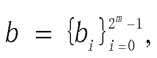


- For example, in an example of the present invention, a pair of Golay complementary sequences may be obtained by using the foregoing formulas:
-
G a128 =[1 1 -1 -1 -1 -1 -1 -1 -1 1 -1 1 1 -1 -1 1 1 1 -1 -1 1 1 1 1 -1 1 -1 1 -1 1 1 -1 -1 -1 1 1 1 1 1 1 1 -1 1 -1 -1 1 1 -1 1 1 -1 -1 1 1 1 1 -1 1 -1 1 -1 1 1 -1 1 1 -1 -1 -1 -1 -1 -1 -1 1 -1 1 1 -1 -1 1 1 1 -1 -1 1 1 1 1 -1 1 -1 1 -1 1 1 -1 1 1 -1 -1 -1 -1 -1 -1 -1 1 -1 1 1 -1 -1 1 -1 -1 1 1 -1 -1 -1 -1 1 -1 1 -1 1 -1 -1 1]; and -
G b128 = [-1 -1 1 1 1 1 1 1 1 -1 1 -1 -1 1 1 -1 -1 -1 1 1 -1 -1 -1 -1 1 -1 1 -1 1 -1 -1 11 1 -1 -1 -1 -1 -1 -1 -1 1 -1 1 1 -1 -1 1 -1 -1 1 1 -1 -1 -1 -1 1 -1 1 -1 1 -1 -1 1 1 1 -1 -1 -1 -1 -1 -1 -1 1 -1 1 1 -1 -1 1 1 1 -1 -1 1 1 1 1 -1 1 -1 1 -1 1 1 -1 1 1 -1 -1 -1 -1 -1 -1 -1 1 -1 1 1 -1 -11 -1 -1 1 1 -1 -1 -1 -1 1 -1 1 -1 1 -1 -1 1]. - Herein, on this basis, seven other pairs of Golay complementary sequences may be further obtained by using the formulas:
-
G a2128 = [1 -1 -1 1 -1 1 -1 1 -1 -1 -1 -1 1 1 -1 -1 1 -1 -1 1 1 -1 1 -1 -1 -1 -1 -1 -1 -1 1 1 -1 1 1 -1 1 -1 1 -1 1 1 1 1 -1 -1 1 1 1 -1 -1 1 1 -1 1 -1-1 -1 -1 -1 -1-1 1 1 1 -1 -1 1 -1 1 -1 1 -1 -1 -1-111 -1 -1 1 -1 -1 1 1 -1 1 -1 -1 -1 -1 -1 -1 -1 1 1 1 -1 -1 1 -1 1 -1 1 -1 -1 -1 -1 1 1 -1 -1 -1 1 1 -1 -1 1 -1 1 1 1 1 1 1 1 -1 -1]; -
G b2128 = [-1 1 1 -1 1 -1 1 -1 1 1 1 1 -1 -1 1 1 -1 1 1 -1 -1 1 -1 1 1 1 1 1 1 1 -1 -1 1 -1 -1 1 -1 1 -1 1 -1 -1 -1 -1 1 1 -1 -1 -1 1 1 -1 -1 1 -1 1 1 1 1 1 1 1 -1 -1 1 -1 -1 1 -1 1 -11 -1 -1 -1-111 -1 -1 1 -1 -1 1 1 -1 1 -1 -1 -1 -1 -1 -1 -1 1 1 1 -1 -1 1 -1 1 -1 1 -1 -1 -1 -1 1 1 -1 -1 -1 1 1 -1 -1 1 -1 1 1 1 1 1 1 1 -1 -1]; -
G a3128 = [1 1 1 -1 1 1 -1 1 -1 -1 -1 1 1 1 -1 1 1 1 1 -1 1 1 -1 1 1 1 1 -1 -1 -1 1 -1 1 1 1 -1 1 1 -1 1 -1 -1 -1 1 1 1 -1 1 -1 -1 -1 1 -1 -1 1 -1 -1 -1 -1 1 1 1 -1 1 1 1 1 -1 1 1 -1 1 -1 -1 -1 1 1 1 -1 1 1 1 1 -1 1 1 -1 1 1 1 1 -1 -1 -1 1 -1 -1 -1 -1 1 -1 -1 1 -1 1 1 1 -1 -1 -1 1 -1 1 1 1 -1 1 1 -1 1 1 1 1 -1 -1 -1 1 -1]; -
G b3128 = [1 1 1 -1 1 1 -1 1 -1 -1 -1 1 1 1 -1 1 1 1 1 -1 1 1 -1 1 1 1 1 -1 -1 -1 1 -1 1 1 1 -1 1 1 -1 1 -1 -1 -1 1 1 1 -1 1 -1 -1 -1 1 -1 -1 1 -1 -1 -1 -1 1 1 1 -1 1 -1 -1 -1 1 -1 -1 1 -1 1 1 1 -1 -1 -1 1 -1 -1 -1 -1 1 -1 -1 1 -1 -1 -1 -1 1 1 1 -1 1 1 1 1 -1 1 1 -1 1 -1 -1 -1 1 1 1 -1 1 -1 -1 -1 1-1-11 -1 -1 -1 -1 1 1 1 -1 1]; -
G a4128 = [1 -1 1 1 1 -1 -1 -1 -1 1 -1 -1 1 -1 -1 -1 1 -1 1 1 1 -1 -1 -1 1 -1 1 1 -1 1 1 1 1 -1 1 1 1 -1 -1 -1 -1 1 -1 -1 1 -1 -1 -1 -1 1 -1 -1 -1 1 1 1 -1 1 -1 -1 1 -1 -1 -1 1 -1 1 1 1 -1 -1 -1 -1 1 -1 -1 1 -1 -1-1 1 -1 1 1 1 -1 -1 -1 1 -1 1 1 -1 1 1 1 -1 1 -1 -1 -1 1 1 1 1 -1 1 1 -1 1 1 1 1 -1 1 1 1 -1 -1 -1 1 -1 1 1 -1 1 1 1]; -
G b4128 = [1 -1 1 1 1 -1 -1 -1 -1 1 -1 -1 1 -1 -1 -1 1 -1 1 1 1 -1 -1 -1 1 -1 1 1 -1 1 1 1 1 -1 1 1 1 -1 -1 -1 -1 1 -1 -1 1 -1 -1 -1 -1 1 -1 -1 -1 1 1 1 -1 1 -1 -1 1 -1 -1 -1 -1 1 -1 -1 -1 1 1 1 1 -1 1 1 -1 1 1 1 -1 1 -1 -1 -1 1 1 1 -1 1 -1 -1 1 -1 -1 -1 1 -1 1 1 1 -1 -1 -1 -1 1 -1 -1 1 -1 -1 -1 -1 1 -1 -1 -1 1 1 1 -1 1 -1 -1 1 -1 -1 -1]; -
G a5128 = [1 1 1 -1 -1 -1 1 -1 1 1 1 -1 1 1 -1 1 1 1 1 -1 -1 -1 1 -1 -1 -1 -1 1 -1 -1 1 -1 1 1 1 -1 -1 -1 1 -1 1 1 1 -1 1 1 -1 1 -1 -1 -1 1 1 1 -1 1 1 1 1 -1 1 1 -1 1 1 1 1 -1 -1 -1 1 -1 1 1 1 -1 1 1 -1 1 1 1 1 -1 -1 -1 1 -1 -1 -1 -1 1 -1 -1 1 -1 -1 -1 -1 1 1 1 -1 1 -1 -1 -1 1 -1 -1 1 -1 1 1 1 -1 -1 -1 1 -1 -1 -1 -1 1 -1-1 1 -1]; -
G b5128 = [1 1 1 -1 -1 -1 1 -1 1 1 1 -1 1 1 -1 1 1 1 1 -1 -1 -1 1 -1 -1 -1 -1 1 -1 -1 1 -1 1 1 1 -1 -1 -1 1 -1 1 1 1 -1 1 1 -1 1 -1 -1 -1 1 1 1 -1 1 1 1 1 -1 1 1 -1 1 -1 -1 -1 1 1 1 -1 1 -1 -1 -1 1 -1 -1 1 -1 -1 -1 -1 1 1 1 -1 1 1 1 1 -1 1 1 -1 1 1 1 1 -1 -1 -1 1 -1 1 1 1 -1 1 1 -1 1 -1 -1 -1 1 1 1 -1 1 1 1 1 -1 1 1 -1 1]; -
G a6128 = [1 -1 1 1 -1 1 1 1 1 -1 1 1 1 -1 -1 -1 1 -1 1 1 -1 1 1 1 -1 1 -1 -1 -1 1 1 1 1 -1 1 1 -1 1 1 1 1 -1 1 1 1 -1 -1 -1 -1 1 -1 -1 1 -1 -1 -1 1 -1 1 1 1 -1 -1 -1 1 -1 1 1 -1 1 1 1 1 -1 1 1 1 -1 -1 -1 1 -1 1 1 -1 1 1 1 -1 1 -1 -1 -1 1 1 1 -1 1 -1 -1 1 -1 -1 -I -1 1 -1 -1 -1 11 1 1 -1 1 1 -11 1 1 -1 1 -1 -1 -1 1 1 1]; -
G b6128 = [1 -1 1 1 -1 1 1 1 1 -1 1 1 1 -1 -1 -1 1 -1 1 1 -1 1 1 1 -1 1 -1 -1 -1 1 1 1 1 -1 11 -1 1 1 1 1 -1 1 1 1 -1 -1 -1-1 1 -1 -1 1 -1 -1 -1 1 -1 1 11 -1 -1 -1 -1 1 -1 -1 1 -1 -1 -1 -1 1 -1 -1 -1 1 1 1 -1 1 -1 -1 1 -1 -1 -1 1 -1 1 1 1 -1 -1 -1 1 -1 1 1 -1 1 1 1 1 -1 1 1 1 -1 -1 -1 -1 1 -1 -1 1 -1 -1 -1 1 -1 1 1 1 -1 -1 -1]; -
G a7128 = [1 1 -1 1 1 1 1 -1 1 1 -1 1 -1 -1 -1 1 1 1 -1 1 1 1 1 -1 -1 -1 1 -1 1 1 1 -1 1 1 -1 1 1 1 1 -1 1 1 -1 1 -1 -1 -1 1 -1 -1 1 -1 -1 -1 -1 1 1 1 -1 1 -1 -1 -1 1 1 1 -1 1 1 1 1 -1 1 1 -1 1 -1 -1 -1 1 1 1 -1 1 1 1 1 -1 -1 -1 1 -1 1 1 1 -1 -1 -1 1 -1 -1 -1 -1 1 -1 -1 1 -1 1 1 1 -1 1 1 -1 1 1 11 -1 -1 -1 1 -1 1 1 1 -1]; -
G b7128 = [1 1 -1 1 1 1 1 -1 1 1 -1 1 -1 -1 -1 1 1 1 -1 1 1 1 1 -1 -1 -1 1 -1 1 1 1 -1 1 1 -1 1 1 1 1 -1 1 1 -1 1 -1 -1 -1 1 -1 -1 1 -1 -1 -1 -1 1 1 1 -1 1 -1 -1 -1 1-1-11 -1 -1 -1 -1 1 -1 -1 1 -1 1 1 1 -1 -1 -1 1 -1 -1 -1 -1 1 1 1 -1 1 -1 -1 -1 1 1 1 -1 1 1 1 1 -1 1 1 -1 1 -1 -1 -1 1 -1 -1 1 -1 -1 -1 -1 1 1 1 -1 1 -1 -1 -1 1]; -
G a8128 = [1 -1 -1 -1 1 -1 1 1 1 -1 -1 -1 -1 1 -1 -1 1 -1 -1 -1 1 -1 1 1 -1 1 1 1 1 -1 1 1 1 -1 -1 -1 1 -1 1 1 1 -1 -1 -1 -1 1 -1 -1 -1 1 1 1 -1 1 -1 -1 1 -1 -1 -1 -1 1 -1 -1 1 -1 -1 -1 1 -1 1 1 1 -1 -1 -1 -1 1 -1 -1 1 -1 -1 -1 1 -1 1 1 -1 1 1 1 1 -1 1 1 -1 1 1 1 -1 1 -1 -1 -1 1 1 1 1 -1 1 1 1 -1 -1 -1 1 -1 1 1 -1 1 1 1 1 -1 1 1]; and -
G b8128 = [1 -1 -1 -1 1 -1 1 1 1 -1 -1 -1 -1 1 -1 -1 1 -1 -1 -1 1 -1 1 1 -1 1 1 1 1 -1 1 1 1 -1 -1 -1 1 -1 1 1 1 -1 -1 -1 -1 1 -1 -1 -1 1 1 1 -1 1 -1 -1 1 -1 -1 -1 -1 1 -1 -1 -1 1 1 1 -1 1 -1 -1 -1 1 1 1 1 -1 1 1 -1 1 1 1 -1 1 -1 -1 1 -1 -1 -1 -1 1 -1 -1 1 -1 -1 -1 1 -1 1 1 1 -1 -1 -1 -1 1 -1 -1-1 1 1 1 -1 1 -1 -1 1 -1 -1 -1 -1 1 -1 -1]. - In addition, four other groups of sequences with lengths of 256, 512, 1024, and 2048 are defined:
- Gai 256 = [
Ga i 128 Gbi 128] Gbi 256 = [Gai 128 -Gbi 128]; - Gai 512 = [Gai 256 Gbi 256] Gbi 512 = [Gai 256 -Gbi 256];
- Gai 1024 = [Gai 512 Gbi 512] Gbi 1024 = [Gai 512 -Gbi 512]; and
- Gai 2048 = [Gai 1024 Gbi 1024] Gbi 2048 = [Gai 1024 -Gbi 1024]
- Optionally, in other possible implementations of the present invention, the Golay complementary sequences may be generated in another manner.
- S502. The transmit end obtains NT orthogonal Golay sequences with a length of 2 × N × L based on the M pairs of Golay complementary sequences with a length of L.
- NT is a quantity of antennas at the transmit end. NT is a positive integer greater than 0. N is a positive integer greater than 0. A value of M is greater than or equal to a value of NT .
- S503. The transmit end adds a cyclic prefix with a length of L ahead of each of the NT orthogonal Golay complementary sequences with a length of 2 × N × L, to obtain beam training sequences applied to a channel having NT antennas.
- Optionally, the cyclic prefix may be a Golay sequence.
- Optionally, in some possible implementations of the present invention, the obtaining NT orthogonal Golay sequences with a length of 2 × N × L based on the M pairs of Golay complementary sequences with a length of L includes:
- obtaining NT pairs of Golay complementary sequences with a length of L from the M pairs of Golay complementary sequences with a length of L; and
- placing repeatedly and alternately each pair of the NT pairs of Golay complementary sequences with a length of L for N times in a first preset manner, to obtain the NT orthogonal Golay sequences with a length of 2 × N × L.
- The placing repeatedly and alternately each Golay complementary sequence with a length of L for N times in a first preset manner means adding a positive sign or a negative sign ahead of each Golay sequence with a length of L when repeatedly placing each Golay complementary sequence with a length of L, to finally obtain the NT orthogonal Golay complementary sequences with a length of 2 × N × L. Adding a negative sign ahead of a Golay sequence means negation of each symbol in the Golay sequence. Adding a positive sign ahead of a Golay sequence means keeping each symbol in the Golay sequence unchanged.
- In this embodiment of the present invention, the first preset manner of placing repeatedly and alternately the Golay complementary sequence is not unique, provided that the finally obtained NT Golay sequences with a length of 2 × N × L are orthogonal to each other.
- Preferably, a value of the quantity N of times of the repeated and alternate placing is 2.
- For example, in an example of the present invention, when the maximum delay Tm of the channel is 72 ns, a symbol rate of the channel is 1.76 Gbps (in this case, there is no channel aggregation, to be specific, channel bonding CB quantity is 1), and a quantity of MIMO antennas is 2, first, any two pairs of Golay
complementary sequences G a1128/G b1128 andG a2128/G b2128 are obtained from the M pairs of Golay complementary sequences generated in step S201, and the two pairs of Golay complementary sequences are repeatedly and alternately placed twice separately, to obtain two sequences [-G b1128,G a1128,G b1128, Ga1128] and [-G b2128,G a2128,G b2128, Ga2128]; or may be repeatedly and alternately placed twice in another manner, to obtain [-G b1128, -G a1128,G b1128, -Ga1128] and [-G b2128,G a2128,G b2128, Ga2128]. In the two cases, the two sequences are orthogonal to each other. - It may be understood that the Golay complementary sequences may be repeatedly and alternately placed in a specific manner to obtain the NT orthogonal Golay sequences with a length of 2 × N × L, and then the cyclic prefix with a length of L is added ahead of each Golay sequence to obtain the beam training sequences for beam training on the channel having NT antennas, so that the beam training sequences can be no longer restricted by a quantity of antennas, a delay spread value of a channel, and a scenario such as multi-channel bonding, and is applicable to different channel scenario configurations.
- Optionally, in other possible implementations of the present invention, the obtaining NT orthogonal Golay sequences with a length of 2 × N × L based on the M pairs of Golay complementary sequences with a length of L includes:
- obtaining ┌NT /2N┐ pairs of Golay complementary sequences with a length of L from the M pairs of Golay complementary sequences with a length of L; and
- placing repeatedly and alternately each pair of the ┌NT /2N┐ pairs of Golay complementary sequences with a length of L for N times in a second preset manner, and multiplying sequences obtained after the repeated and alternate placing by a preset orthogonal matrix, to obtain the NT orthogonal Golay sequences with a length of 2 × N × L, where the preset orthogonal matrix is a 2N-order orthogonal matrix.
- Preferably, a value of N is 2, so that the preset orthogonal matrix is a 4-order orthogonal matrix.
- The placing repeatedly and alternately each pair of the ┌NT /2N┐ pairs of Golay complementary sequences with a length of L for N times in a second preset manner may be: placing repeatedly and alternately each pair of Golay complementary sequences with a length of L among the Golay complementary sequences in any manner, to obtain ┌NT /2N┐ Golay sequences with a length of 2 × N × L. The ┌NT /2N┐ Golay sequences with a length of 2 × N × L that are obtained after the placing in the second preset manner are not necessarily orthogonal to each other.
- Preferably, when the value of N is 2, the preset orthogonal matrix is the 4-order orthogonal matrix. Therefore, ┌NT /4┐ Golay sequences with a length of 2 × N × L are multiplied by the 4-order orthogonal matrix to obtain ┌NT /4┐ × 4 orthogonal Golay sequences with a length of 2 × N × L, and then NT Golay sequences are selected from the ┌NT /4┐ × 4 orthogonal Golay sequences with a length of 2 × N × L to obtain NT orthogonal Golay sequences with a length of 2 × N × L.
- For example, in an example of the present invention, when the maximum delay Tm of the channel is 72 ns, a symbol rate of the channel is 3.52 Gbps (in this case, a channel bonding CB quantity is 2), and a quantity of MIMO antennas is 8, first, any two pairs of Golay complementary sequences Ga1256/Gb1256 and Ga2256/Gb2256 are obtained from the M pairs of Golay complementary sequences generated in step S301, and the two pairs of Golay complementary sequences are repeatedly and alternately placed twice, to obtain sequences [-Gb1256, Ga1256, Gb1256, Ga1256] and [-Gb2256, Ga2256, Gb2256, Ga2256]. Then the two pairs of sequences are multiplied by the 4-order orthogonal matrix P to obtain eight orthogonal Golay sequences, which are specifically as follows:


- It may be understood that the NT orthogonal Golay complementary sequences with a length of 2 × N × L may be obtained through multiplication by the orthogonal matrix, where L is the signal length corresponding to the maximum delay Tm of the channel; and the cyclic prefix with a length of L is added ahead of each Golay sequence to obtain the beam training sequences for beam training on the channel having NT antennas, so that the beam training sequence can be no longer restricted by a quantity of antennas, a delay spread value of a channel, and a scenario such as multi-channel bonding, and is applicable to different channel scenario configurations.
- It can be learned that, in the technical solution provided in this embodiment of the present invention, the beam training sequences related to the quantity of antennas, the maximum delay of the channel, and the channel bonding quantity are generated. Therefore, a beam training sequence can be no longer restricted by a quantity of antennas, a delay spread value of a channel, and a scenario such as multi-channel bonding provided that the beam training sequence satisfies the foregoing conditions, so that the beam training sequence is applicable to different channel scenario configurations.
-
FIG. 6-a is a schematic flowchart of a third embodiment of a beam training sequence design method according to an embodiment of the present invention. In the method shown inFIG. 6-a , for content that is the same as or similar to content in the method shown inFIG. 4 orFIG. 5 , refer to detailed descriptions inFIG. 4 orFIG. 5 . Details are not described herein again. As shown inFIG. 6-a , the method includes the following steps. - S601. Generate M pairs of Golay complementary sequences with a length of L in a preset Golay complementary sequence generation manner.
- The M pairs of Golay complementary sequences with a length of L are defined in a finite ZH field. Each pair of the M pairs of Golay complementary sequences with a length of L includes two Golay complementary sequences with a length of L. L is a signal length corresponding to a maximum delay Tm of a channel. Both M and L are positive integers greater than 0.
- S602. Obtain NT pairs of Golay complementary sequences with a length of L from the M pairs of Golay complementary sequences with a length of L.
- NT is a quantity of antennas at a transmit end. NT is a positive integer greater than 0. N is a positive integer greater than 0. A value of M is greater than or equal to a value of NT .
- S603. Place repeatedly and alternately each pair of the NT pairs of Golay complementary sequences with a length of L for N times in a first preset manner, to obtain NT orthogonal Golay sequences with a length of 2 × N × L.
- S604. Add a Golay complementary sequence cyclic prefix with a length of L ahead of each of the NT orthogonal Golay complementary sequences with a length of 2 × N × L, to obtain beam training sequences applied to a channel having NT antennas.
- Specifically, the following describes examples of the beam training sequence generation method in different channel scenarios.
- In a first embodiment, it is assumed that the maximum delay Tm of the to-be-estimated channel is 72 ns, a symbol rate Rs is 1.76 Gbps (CB = 1), and a quantity NT of MIMO antennas is 2.
- Based on the solution in this embodiment, L = 2 m = 2log
2 └RsTm ┘ = 128, and two pairs of Golaycomplementary sequences G a1128/G b1128 andG a2128/G b2128 may be generated. - Then the two pairs of Golay complementary sequences are repeatedly and alternately placed twice separately, and the cyclic prefix with a length of L is added, to construct a beam training sequence E-T/R. For details, refer to
FIG. 6-b. FIG. 6-b is a first schematic diagram of a beam training sequence according to a third embodiment of the present invention. - In a second embodiment, it is assumed that the maximum delay Tm of the to-be-estimated channel is 72 ns, a symbol rate Rs is 1.76 Gbps (CB = 1), and a quantity NT of MIMO antennas is 4.
- Based on the solution in this embodiment, L = 2 m = 2log
2 └RsTm ┘ = 128, and four pairs of Golaycomplementary sequences G a1128/G b1128,G a2128/G b2128,G a3128/G b3128, andG a4128/G b4128 may be generated. - Then the four pairs of Golay complementary sequences are repeatedly and alternately placed twice separately, and the cyclic prefix with a length of L is added, to construct a beam training sequence E-T/R. Specifically, the beam training sequence E-T/R may be generated based on
FIG. 6-b. FIG. 6-b is a first schematic diagram of a beam training sequence according to an embodiment of the present invention. - In a third embodiment, it is assumed that the maximum delay Tm of the to-be-estimated channel is 72 ns, a symbol rate Rs is 1.76 Gbps (CB = 1), and a quantity NT of MIMO antennas is 8.
- Based on the solution in this embodiment, L = 2 m = 2log
2 └RsTm ┘ = 128, and eight pairs of Golaycomplementary sequences G a1128/G b1128,G a2128/G b2128,G a3128/G b3128,G a4128/G b4128,G a5128/G b5128,G a6128/G b6128,G a7128/G b7128, andG a8128/G b8128 may be generated. - Then the eight pairs of Golay complementary sequences are repeatedly and alternately placed twice separately, and the cyclic prefix with a length of L is added, to construct a beam training sequence E-T/R. Specifically, the beam training sequence E-T/R may be generated based on
FIG. 6-b . - In a fourth embodiment, it is assumed that the maximum delay Tm of the to-be-estimated channel is 72 ns, a symbol rate Rs is 3.52 Gbps (CB = 2), and a quantity NT of SISO antennas is 1.
- Based on the solution in this embodiment, L = 2 m = 2log
2 └RsTm ┘ = 256, and one pair of Golay complementary sequences Ga1256/Gb1256 is generated. - Then the one pair of Golay complementary sequences is repeatedly and alternately placed twice separately, and the cyclic prefix with a length of L is added, to construct a beam training sequence E-T/R. Specifically, the beam training sequence E-T/R may be generated based on
FIG. 6-b . - In a fifth embodiment, it is assumed that the maximum delay Tm of the to-be-estimated channel is 72 ns, a symbol rate Rs is 3.52 Gbps (CB = 2), and a quantity NT of MIMO antennas is 2.
- Based on the solution in this embodiment, L = 2 m = 2log
2 └RsTm ┘ = 256, and two pairs of Golay complementary sequences Ga1256/Gb1256 and Ga2256/Gb2256 may be generated. - Then the two pairs of Golay complementary sequences are repeatedly and alternately placed twice separately, and the cyclic prefix with a length of L is added, to construct a beam training sequence E-T/R. Specifically, the beam training sequence E-T/R may be generated based on
FIG. 6-b . - In a sixth embodiment, it is assumed that the maximum delay Tm of the to-be-estimated channel is 72 ns, a symbol rate Rs is 3.52 Gbps (CB = 2), and a quantity NT of MIMO antennas is 4.
- Based on the solution in this embodiment, L = 2 m = 2log
2 └RsTm ┘ = 256, and four pairs of Golay complementary sequences Ga1256/Gb1256, Ga2256/Gb2256, Ga3256/Gb3256, and Ga4256/Gb4256 may be generated. - Then the two pairs of Golay complementary sequences are repeatedly and alternately placed twice separately, and the cyclic prefix with a length of L is added, to construct a beam training sequence E-T/R. Specifically, the beam training sequence E-T/R may be generated based on
FIG. 6-b . - In a seventh embodiment, it is assumed that the maximum delay Tm of the to-be-estimated channel is 72 ns, a symbol rate Rs is 3.52 Gbps (CB = 2), and a quantity NT of MIMO antennas is 8.
- Based on the solution in this embodiment, L = 2 m = 2log
2 └RsTm ┘ = 256, and eight pairs of Golay complementary sequences Ga1256/Gb1256, Ga2256/Gb2256, Ga3256/Gb3256, Ga4256/Gb4256, Ga5256/Gb5256, Ga6256/Gb6256, Ga7256/Gb7256, and Ga8256/Gb8256 may be generated. - Then the two pairs of Golay complementary sequences are repeatedly and alternately placed twice separately, and the cyclic prefix with a length of L is added, to construct a beam training sequence E-T/R. Specifically, the beam training sequence E-T/R may be generated based on
FIG. 6-b . - In an eighth embodiment, it is assumed that the maximum delay Tm of the to-be-estimated channel is 72 ns, a symbol rate Rs is 5.28 Gbps or 7.04 Gbps (CB = 3 or CB = 4), and a quantity NT of SISO antennas is 1.
- Based on the solution in this embodiment, L = 2 m = 2log
2 └RsTm ┘ = 512, and one pair of Golay complementary sequences Ga1512/Gb1512 is generated. - Then the one pair of Golay complementary sequences is repeatedly and alternately placed twice separately, and the cyclic prefix with a length of L is added, to construct a beam training sequence E-T/R. Specifically, the beam training sequence E-T/R may be generated based on
FIG. 6-b . - In a ninth embodiment, it is assumed that the maximum delay Tm of the to-be-estimated channel is 72 ns, a symbol rate Rs is 5.28 Gbps or 7.04 Gbps (CB = 3 or CB = 4), and a quantity NT of MIMO antennas is 2.
- Based on the solution in this embodiment, L = 2 m = 2log
2 └RsTm ┘ = 512, and two pairs of Golay complementary sequences Ga1512/Gb1512 and Ga2512/Gb2512 are generated. - Then the two pairs of Golay complementary sequences are repeatedly and alternately placed twice separately, and the cyclic prefix with a length of L is added, to construct a beam training sequence E-T/R. Specifically, the beam training sequence E-T/R may be generated based on
FIG. 6-b . - In a tenth embodiment, it is assumed that the maximum delay Tm of the to-be-estimated channel is 72 ns, a symbol rate Rs is 5.28 Gbps or 7.04 Gbps (CB = 3 or CB = 4), and a quantity NT of MIMO antennas is 4.
- Based on the solution in this embodiment, L = 2 m = 2log
2 └RsTm ┘ = 512, and four pairs of Golay complementary sequences Ga1512/Gb1512, Ga2512/Gb2512, Ga3512/Gb3512, and Ga4512/Gb4512 are generated. - Then the two pairs of Golay complementary sequences are repeatedly and alternately placed twice separately, and the cyclic prefix with a length of L is added, to construct a beam training sequence E-T/R. Specifically, the beam training sequence E-T/R may be generated based on
FIG. 6-b . - In an eleventh embodiment, it is assumed that the maximum delay Tm of the to-be-estimated channel is 72 ns, a symbol rate Rs is 5.28 Gbps or 7.04 Gbps (CB = 3 or CB = 4), and a quantity NT of MIMO antennas is 8.
- Based on the solution in this embodiment, L = 2 m = 2log
2 └RsTm ┘ = 512, and eight pairs of Golay complementary sequences Ga1512/Gb1512, Ga2512/Gb2512, Ga3512/Gb3512, Ga4512/Gb4512, Ga5512/Gb5512, Ga6512/Gb6512, Ga7512/Gb7512, and Ga8512/Gb8512 are generated. - Then the eight pairs of Golay complementary sequences are repeatedly and alternately placed twice separately, and the cyclic prefix with a length of L is added, to construct a beam training sequence E-T/R. Specifically, the beam training sequence E-T/R may be generated based on
FIG. 6-b . - In a twelfth embodiment, it is assumed that the maximum delay Tm of the to-be-estimated channel is 300 ns, a symbol rate Rs is 1.76 Gbps (CB = 1), and a quantity NT of SISO antennas is 1.
- Based on the solution in this embodiment, L = 2 m = 2log
2 └RsTm ┘ = 512, and one pair of Golay complementary sequences Ga1512/Gb1512 is generated. - Then the one pair of Golay complementary sequences is repeatedly and alternately placed twice separately, and the cyclic prefix with a length of L is added, to construct a beam training sequence E-T/R. Specifically, the beam training sequence E-T/R may be generated based on
FIG. 6-b . - In a thirteenth embodiment, it is assumed that the maximum delay Tm of the to-be-estimated channel is 300 ns, a symbol rate Rs is 1.76 Gbps (CB = 1), and a quantity NT of MIMO antennas is 2.
- Based on the solution in this embodiment, L = 2 m = 2log
2 └RsTm ┘ = 512, and two pairs of Golay complementary sequences Ga1512/Gb1512 and Ga2512/Gb2512 are generated. - Then the two pairs of Golay complementary sequences are repeatedly and alternately placed twice separately, and the cyclic prefix with a length of L is added, to construct a beam training sequence E-T/R. Specifically, the beam training sequence E-T/R may be generated based on
FIG. 6-b . - In a fourteenth embodiment, it is assumed that the maximum delay Tm of the to-be-estimated channel is 300 ns, a symbol rate Rs is 1.76 Gbps (CB = 1), and a quantity NT of MIMO antennas is 4.
- Based on the solution in this embodiment, L = 2 m = 2log
2 └RsTm ┘ = 512, and four pairs of Golay complementary sequences Ga1512/Gb1512, Ga2512/Gb2512, Ga3512/Gb3512, and Ga4512/Gb4512 are generated. - Then the four pairs of Golay complementary sequences are repeatedly and alternately placed twice separately, and the cyclic prefix with a length of L is added, to construct a beam training sequence E-T/R. Specifically, the beam training sequence E-T/R may be generated based on
FIG. 6-b . - In a fifteenth embodiment, it is assumed that the maximum delay Tm of the to-be-estimated channel is 300 ns, a symbol rate Rs is 1.76 Gbps (CB = 1), and a quantity NT of MIMO antennas is 8.
- Based on the solution in this embodiment, L = 2 m = 2log
2 └RsTm ┘ = 512, and eight pairs of Golay complementary sequences Ga1512/Gb1512, Ga2512/Gb2512, Ga3512/Gb3512, Ga4512/Gb4512, Ga5512/Gb5512, Ga6512/Gb6512, Ga7512/Gb7512, and Ga8512/Gb8512 are generated. - Then the eight pairs of Golay complementary sequences are repeatedly and alternately placed twice separately, and the cyclic prefix with a length of L is added, to construct a beam training sequence E-T/R. Specifically, the beam training sequence E-T/R may be generated based on
FIG. 6-b . - In a sixteenth embodiment, it is assumed that the maximum delay Tm of the to-be-estimated channel is 300 ns, a symbol rate Rs is 3.52 Gbps (CB = 2), and a quantity NT of SISO antennas is 1.
- Based on the solution in this embodiment, L = 2 m = 2log
2 └RsTm ┘ = 1024, and one pair of Golay complementary sequences Ga11024/Gb11024 is generated. - Then the one pair of Golay complementary sequences is repeatedly and alternately placed twice separately, and the cyclic prefix with a length of L is added, to construct a beam training sequence E-T/R. Specifically, the beam training sequence E-T/R may be generated based on
FIG. 6-b . - In a seventeenth embodiment, it is assumed that the maximum delay Tm of the to-be-estimated channel is 300 ns, a symbol rate Rs is 3.52 Gbps (CB = 2), and a quantity NT of MIMO antennas is 2.
- Based on the solution in this embodiment, L = 2 m = 2log
2 └RsTm ┘ = 1024, and two pairs of Golay complementary sequences Ga11024/Gb11024 and Ga21024/Gb21024 are generated. - Then the two pairs of Golay complementary sequences are repeatedly and alternately placed twice separately, and the cyclic prefix with a length of L is added, to construct a beam training sequence E-T/R. Specifically, the beam training sequence E-T/R may be generated based on
FIG. 6-b . - In an eighteenth embodiment, it is assumed that the maximum delay Tm of the to-be-estimated channel is 300 ns, a symbol rate Rs is 3.52 Gbps (CB = 2), and a quantity NT of MIMO antennas is 4.
- Based on the solution in this embodiment, L = 2 m = 2log
2 └RsTm ┘ = 1024, and four pairs of Golay complementary sequences Ga11024/Gb11024, Ga21024/Gb21024, Ga31024/Gb31024, and Ga41024/Gb41024 are generated. - Then the four pairs of Golay complementary sequences are repeatedly and alternately placed twice separately, and the cyclic prefix with a length of L is added, to construct a beam training sequence E-T/R. Specifically, the beam training sequence E-T/R may be generated based on
FIG. 6-b . - In a nineteenth embodiment, it is assumed that the maximum delay Tm of the to-be-estimated channel is 300 ns, a symbol rate Rs is 3.52 Gbps (CB = 2), and a quantity NT of MIMO antennas is 8.
- Based on the solution in this embodiment, L = 2 m = 2log
2 └RsTm ┘ = 1024, and eight pairs of Golay complementary sequences Ga11024/Gb11024, Ga21024/Gb21024, Ga31024/Gb31024, Ga41024/Gb41024, Ga51024/Gb51024, Ga61024/Gb61024, Ga71024/Gb71024, and Ga81024/Gb81024 are generated. - Then the eight pairs of Golay complementary sequences are repeatedly and alternately placed twice separately, and the cyclic prefix with a length of L is added, to construct a beam training sequence E-T/R. Specifically, the beam training sequence E-T/R may be generated based on
FIG. 6-b . - In a twentieth embodiment, it is assumed that the maximum delay Tm of the to-be-estimated channel is 300 ns, a symbol rate Rs is 5.28 Gbps or 7.04 Gbps (CB = 3 or CB = 4), and a quantity NT of SISO antennas is 1.
- Based on the solution in this embodiment, L = 2 m = 2log
2 └RsTm ┘ = 2048, and one pair of Golay complementary sequences Ga12048/Gb12048 is generated. - Then the one pair of Golay complementary sequences is repeatedly and alternately placed twice separately, and the cyclic prefix with a length of L is added, to construct a beam training sequence E-T/R. Specifically, the beam training sequence E-T/R may be generated based on
FIG. 6-b . - In a twenty-first embodiment, it is assumed that the maximum delay Tm of the to-be-estimated channel is 300 ns, a symbol rate Rs is 5.28 Gbps or 7.04 Gbps (CB = 3 or CB = 4), and a quantity NT of MIMO antennas is 2.
- Based on the solution in this embodiment, L = 2 m = 2log
2 └RsTm ┘ = 2048, and two pairs of Golay complementary sequences Ga12048/Gb12048 and Ga22048/Gb22048 are generated. - Then the two pairs of Golay complementary sequences are repeatedly and alternately placed twice separately, and the cyclic prefix with a length of L is added, to construct a beam training sequence E-T/R. Specifically, the beam training sequence E-T/R may be generated based on
FIG. 6-b . - In a twenty-second embodiment, it is assumed that the maximum delay Tm of the to-be-estimated channel is 300 ns, a symbol rate Rs is 5.28 Gbps or 7.04 Gbps (CB = 3 or CB = 4), and a quantity NT of MIMO antennas is 4.
- Based on the solution in this embodiment, L = 2 m = 2log
2 └RsTm ┘ = 2048, and four pairs of Golay complementary sequences Ga12048/Gb12048, Ga22048/Gb22048, Ga32048/Gb32048, and Ga42048/Gb42048 are generated. - Then the four pairs of Golay complementary sequences are repeatedly and alternately placed twice separately, and the cyclic prefix with a length of L is added, to construct a beam training sequence E-T/R. Specifically, the beam training sequence E-T/R may be generated based on
FIG. 6-b . - In a twenty-third embodiment, it is assumed that the maximum delay Tm of the to-be-estimated channel is 300 ns, a symbol rate Rs is 5.28 Gbps or 7.04 Gbps (CB = 3 or CB = 4), and a quantity NT of MIMO antennas is 8.
- Based on the solution in this embodiment, L = 2 m = 2log
2 └RsTm ┘ = 2048, and eight pairs of Golay complementary sequences Ga12048/Gb12048, Ga22048/Gb22048, Ga32048/Gb32048, Ga42048/Gb42048, Ga52048/Gb52048, Ga62048/Gb62048, Ga72048/Gb72048, and Ga82048/Gb82048 are generated. - Then the eight pairs of Golay complementary sequences are repeatedly and alternately placed twice separately, and the cyclic prefix with a length of L is added, to construct a beam training sequence E-T/R. Specifically, the beam training sequence E-T/R may be generated based on
FIG. 6-b . - It can be learned that, in the technical solution provided in this embodiment of the present invention, the Golay complementary sequences may be repeatedly and alternately placed in a specific manner to obtain the NT orthogonal Golay sequences with a length of 2 × N × L, and then the cyclic prefix with a length of L is added ahead of each Golay sequence to obtain the beam training sequences for beam training on the channel having NT antennas, so that the beam training sequences can be no longer restricted by a quantity of antennas, a delay spread value of a channel, and a scenario such as multi-channel bonding, and is applicable to different channel scenario configurations.
-
FIG. 7-a is a schematic flowchart of a fourth embodiment of a beam training sequence design method according to an embodiment of the present invention. In the method shown inFIG. 7-a , for content that is the same as or similar to content in the method shown inFIG. 4 ,FIG. 5 , orFIG. 6-a , refer to detailed descriptions inFIG. 4 ,FIG. 5 , orFIG. 6-a . Details are not described herein again. The method includes the following steps. - S701. Generate M pairs of Golay complementary sequences with a length of L in a preset Golay complementary sequence generation manner.
- The M pairs of Golay complementary sequences with a length of L are defined in a finite ZH field. Each pair of the M pairs of Golay complementary sequences with a length of L includes two Golay complementary sequences with a length of L. L is a signal length corresponding to a maximum delay Tm of a channel. Both M and L are positive integers greater than 0.
- S702. Obtain ┌NT /4┐ pairs of Golay complementary sequences with a length of L from the M pairs of Golay complementary sequences with a length of L.
- NT is a quantity of antennas at a transmit end. NT is a positive integer greater than 0. N is a positive integer greater than 0. A value of M is greater than or equal to a value of NT .
- S703. Place repeatedly and alternately each pair of the ┌NT /4┐ pairs of Golay complementary sequences with a length of L for N times in a second preset manner, and multiply sequences obtained after the repeated and alternate placing by a preset orthogonal matrix, to obtain NT orthogonal Golay sequences with a length of 2 × N × L, where the preset orthogonal matrix is a 2N-order orthogonal matrix.
- Preferably, a value of N is 2, so that the preset orthogonal matrix is a 4-order orthogonal matrix.
- S704. Add a Golay complementary sequence cyclic prefix with a length of L ahead of each of the NT orthogonal Golay complementary sequences with a length of 2 × N × L, to obtain beam training sequences applied to a channel having NT antennas.
- Specifically, the following describes examples of methods for generating a beam training sequence by using this method in different channel scenarios.
- In a first embodiment, it is assumed that the maximum delay Tm of the to-be-estimated channel is 72 ns, a symbol rate Rs is 1.76 Gbps (CB = 1), and a quantity NT of MIMO antennas is 2.
- Based on the solution in this embodiment, L = 2 m = 2log
2 └RsTm ┘ = 128, and one pair of Golaycomplementary sequences G a1128/G b1128 is generated. - Then the one pair of Golay complementary sequences is repeatedly and alternatively placed twice, and sequences obtained after the repeated and alternate placing are multiplied by a 4×4 orthogonal matrix P, to obtain four orthogonal sequences:

- Any two sequences are selected from the orthogonal sequences, and the cyclic prefix with a length of L is added, to construct a beam training sequence E-T/R. Specifically, the beam training sequence E-T/R may be generated based on
FIG. 7-c. FIG. 7-c is a third schematic diagram of a beam training sequence according to an embodiment of the present invention. - In a second embodiment, it is assumed that the maximum delay Tm of the to-be-estimated channel is 72 ns, a symbol rate Rs is 1.76 Gbps (CB = 1), and a quantity NT of MIMO antennas is 4.
- Based on the solution in this embodiment, L = 2 m = 2log2└RsTm┘ = 128, and one pair of Golay
complementary sequences G a1128/G b1128 is generated. - Then the one pair of Golay complementary sequences is repeatedly and alternatively placed twice, and sequences obtained after the repeated and alternate placing are multiplied by a 4×4 orthogonal matrix P, to obtain four orthogonal sequences:

- Four of the orthogonal sequences are selected, and the cyclic prefix with a length of L is added, to construct a beam training sequence E-T/R. Specifically, the beam training sequence E-T/R may be generated based on
FIG. 7-d. FIG. 7-d is a fourth schematic diagram of a beam training sequence according to an embodiment of the present invention. - In a third embodiment, it is assumed that the maximum delay Tm of the to-be-estimated channel is 72 ns, a symbol rate Rs is 1.76 Gbps (CB = 1), and a quantity NT of MIMO antennas is 8.
- Based on the solution in this embodiment, L = 2 m = 2log2└RsTm┘ = 128, and two pairs of Golay
complementary sequences G a1128/G b1128 andG a2128/G b2128 are generated. - Then the two pairs of Golay complementary sequences are repeatedly and alternatively placed twice, and sequences obtained after the repeated and alternate placing are multiplied by a 4×4 orthogonal matrix P, to obtain eight orthogonal sequences:


- Eight of the orthogonal sequences are selected, and the cyclic prefix with a length of L is added, to construct a beam training sequence E-T/R. Specifically, the beam training sequence E-T/R may be generated based on
FIG. 7-e. FIG. 7-e is a fifth schematic diagram of a beam training sequence according to an embodiment of the present invention. - In a fourth embodiment, it is assumed that the maximum delay Tm of the to-be-estimated channel is 72 ns, a symbol rate Rs is 3.52 Gbps (CB = 2), and a quantity NT of SISO antennas is 1.
- Based on the solution in this embodiment, L = 2 m = 2log
2 └RsTm ┘ = 256, and one pair of Golay complementary sequences Ga1256/Gb1256 is generated. - Then the one pair of Golay complementary sequences is repeatedly and alternatively placed twice, and sequences obtained after the repeated and alternate placing are multiplied by a 4×4 orthogonal matrix P, to obtain four orthogonal sequences:

- Any two sequences are selected from the orthogonal sequences, and the cyclic prefix with a length of L is added, to construct a beam training sequence E-T/R. Specifically, the beam training sequence E-T/R may be generated based on
FIG. 7-b. FIG. 7-b is a second schematic diagram of a beam training sequence according to an embodiment of the present invention. - In a fifth embodiment, it is assumed that the maximum delay Tm of the to-be-estimated channel is 72 ns, a symbol rate Rs is 3.52 Gbps (CB = 2), and a quantity NT of MIMO antennas is 2.
- Based on the solution in this embodiment, L = 2 m = 2log
2 └RsTm ┘ = 256, and one pair of Golay complementary sequences Ga1256/Gb1256 is generated. - Then the one pair of Golay complementary sequences is repeatedly and alternatively placed twice, and sequences obtained after the repeated and alternate placing are multiplied by a 4×4 orthogonal matrix P, to obtain four orthogonal sequences:

- Any two sequences are selected from the orthogonal sequences, and the cyclic prefix with a length of L is added, to construct a beam training sequence E-T/R. Specifically, the beam training sequence E-T/R may be generated based on
FIG. 7-c . - In a sixth embodiment, it is assumed that the maximum delay Tm of the to-be-estimated channel is 72 ns, a symbol rate Rs is 3.52 Gbps (CB = 2), and a quantity NT of MIMO antennas is 4.
- Based on the solution in this embodiment, L = 2 m = 2log
2 └RsTm ┘ = 256, and one pair of Golay complementary sequences Ga1256/Gb1256 is generated. - Then the one pair of Golay complementary sequences is repeatedly and alternatively placed twice, and sequences obtained after the repeated and alternate placing are multiplied by a 4×4 orthogonal matrix P, to obtain four orthogonal sequences:

- Four of the orthogonal sequences are selected, and the cyclic prefix with a length of L is added, to construct a beam training sequence E-T/R. Specifically, the beam training sequence E-T/R may be generated based on
FIG. 7-d . - In a seventh embodiment, it is assumed that the maximum delay Tm of the to-be-estimated channel is 72 ns, a symbol rate Rs is 3.52 Gbps (CB = 2), and a quantity NT of MIMO antennas is 8.
- Based on the solution in this embodiment, L = 2 m = 2log
2 └RsTm ┘ = 256, and two pairs of Golay complementary sequences Ga1256/Gb1256 and Ga2256/Gb2256 may be generated. - Then the two pairs of Golay complementary sequences are repeatedly and alternatively placed twice, and sequences obtained after the repeated and alternate placing are multiplied by a 4×4 orthogonal matrix P, to obtain eight orthogonal sequences:


- Eight sequences are selected from the orthogonal sequences, and the cyclic prefix with a length of L is added, to construct a beam training sequence E-T/R. Specifically, the beam training sequence E-T/R may be generated based on
FIG. 7-e . - In an eighth embodiment, it is assumed that the maximum delay Tm of the to-be-estimated channel is 72 ns, a symbol rate Rs is 5.28 Gbps or 7.04 Gbps (CB = 3 or CB = 4), and a quantity NT of SISO antennas is 1.
- Based on the solution in this embodiment, L = 2 m = 2log
2 └RsTm ┘ = 512, and one pair of Golay complementary sequences Ga1512/Gb1512 is generated. - Then the one pair of Golay complementary sequences is repeatedly and alternatively placed twice, and sequences obtained after the repeated and alternate placing are multiplied by a 4×4 orthogonal matrix P, to obtain four orthogonal sequences:

- Any one sequence is selected from the orthogonal sequences, and the cyclic prefix with a length of L is added, to construct a beam training sequence E-T/R. Specifically, the beam training sequence E-T/R may be generated based on
FIG. 7-b . - In a ninth embodiment, it is assumed that the maximum delay Tm of the to-be-estimated channel is 72 ns, a symbol rate Rs is 5.28 Gbps or 7.04 Gbps (CB = 3 or CB = 4), and a quantity NT of MIMO antennas is 2.
- Based on the solution in this embodiment, L = 2 m = 2log
2 └RsTm ┘ = 512, and one pair of Golay complementary sequences Ga1512/Gb1512 is generated. - Then the one pair of Golay complementary sequences is repeatedly and alternatively placed twice, and sequences obtained after the repeated and alternate placing are multiplied by a 4×4 orthogonal matrix P, to obtain four orthogonal sequences:

- Any two sequences are selected from the orthogonal sequences, and the cyclic prefix with a length of L is added, to construct a beam training sequence E-T/R. Specifically, the beam training sequence E-T/R may be generated based on
FIG. 7-c . - In a tenth embodiment, it is assumed that the maximum delay Tm of the to-be-estimated channel is 72 ns, a symbol rate Rs is 5.28 Gbps or 7.04 Gbps (CB = 3 or CB = 4), and a quantity NT of MIMO antennas is 4.
- Based on the solution in this embodiment, L = 2 m = 2log
2 └RsTm ┘ = 512, and one pair of Golay complementary sequences Ga1512/Gb1512 is generated. - Then the one pair of Golay complementary sequences is repeatedly and alternatively placed twice, and sequences obtained after the repeated and alternate placing are multiplied by a 4×4 orthogonal matrix P, to obtain four orthogonal sequences:

- Any four sequences are selected from the orthogonal sequences, and the cyclic prefix with a length of L is added, to construct a beam training sequence E-T/R. Specifically, the beam training sequence E-T/R may be generated based on
FIG. 7-d . - In an eleventh embodiment, it is assumed that the maximum delay Tm of the to-be-estimated channel is 72 ns, a symbol rate Rs is 5.28 Gbps or 7.04 Gbps (CB = 3 or CB = 4), and a quantity NT of MIMO antennas is 8.
- Based on the solution in this embodiment, L = 2 m = 2log
2 └RsTm ┘ = 512, and two pairs of Golay complementary sequences Ga1512/Gb1512 and Ga2512/Gb2512 are generated. - Then the two pairs of Golay complementary sequences are repeatedly and alternatively placed twice, and sequences obtained after the repeated and alternate placing are multiplied by a 4×4 orthogonal matrix P, to obtain eight orthogonal sequences:


- Eight of the orthogonal sequences are selected, and the cyclic prefix with a length of L is added, to construct a beam training sequence E-T/R. Specifically, the beam training sequence E-T/R may be generated based on
FIG. 7-e . - In a twelfth embodiment, it is assumed that the maximum delay Tm of the to-be-estimated channel is 300 ns, a symbol rate Rs is 1.76 Gbps (CB = 1), and a quantity NT of SISO antennas is 1.
- Based on the solution in this embodiment, L = 2 m = 2log
2 └RsTm ┘ = 512, and one pair of Golay complementary sequences Ga1512/Gb1512 is generated. - Then the one pair of Golay complementary sequences is repeatedly and alternatively placed twice, and sequences obtained after the repeated and alternate placing are multiplied by a 4×4 orthogonal matrix P, to obtain four orthogonal sequences:

- Any one sequence is selected from the orthogonal sequences, and the cyclic prefix with a length of L is added, to construct a beam training sequence E-T/R. Specifically, the beam training sequence E-T/R may be generated based on
FIG. 7-b . - In a thirteenth embodiment, it is assumed that the maximum delay Tm of the to-be-estimated channel is 300 ns, a symbol rate Rs is 1.76 Gbps (CB = 1), and a quantity NT of MIMO antennas is 2.
- Based on the solution in this embodiment, L = 2 m = 2log
2 └RsTm ┘ = 512, and one pair of Golay complementary sequences Ga1512/Gb1512 is generated. - Then the one pair of Golay complementary sequences is repeatedly and alternatively placed twice, and sequences obtained after the repeated and alternate placing are multiplied by a 4×4 orthogonal matrix P, to obtain four orthogonal sequences:

- Any two sequences are selected from the orthogonal sequences, and the cyclic prefix with a length of L is added, to construct a beam training sequence E-T/R. Specifically, the beam training sequence E-T/R may be generated based on
FIG. 7-c . - In a fourteenth embodiment, it is assumed that the maximum delay Tm of the to-be-estimated channel is 300 ns, a symbol rate Rs is 1.76 Gbps (CB = 1), and a quantity NT of MIMO antennas is 4.
- Based on the solution in this embodiment, L = 2 m = 2log
2 └RsTm ┘ = 512, and one pair of Golay complementary sequences Ga1512/Gb1512 is generated. - Then the one pair of Golay complementary sequences is repeatedly and alternatively placed twice, and sequences obtained after the repeated and alternate placing are multiplied by a 4×4 orthogonal matrix P, to obtain four orthogonal sequences:

- Four of the orthogonal sequences are selected, and the cyclic prefix with a length of L is added, to construct a beam training sequence E-T/R. Specifically, the beam training sequence E-T/R may be generated based on
FIG. 7-d . - In a fifteenth embodiment, it is assumed that the maximum delay Tm of the to-be-estimated channel is 300 ns, a symbol rate Rs is 1.76 Gbps (CB = 1), and a quantity NT of MIMO antennas is 8.
- Based on the solution in this embodiment, L = 2 m = 2log
2 └RsTm ┘ = 512, and two pairs of Golay complementary sequences Ga1512/Gb1512 and Ga2512/Gb2512 are generated. - Then the two pairs of Golay complementary sequences are repeatedly and alternatively placed twice, and sequences obtained after the repeated and alternate placing are multiplied by a 4×4 orthogonal matrix P, to obtain eight orthogonal sequences:


- Eight of the orthogonal sequences are selected, and the cyclic prefix with a length of L is added, to construct a beam training sequence E-T/R. Specifically, the beam training sequence E-T/R may be generated based on
FIG. 7-e . - In a sixteenth embodiment, it is assumed that the maximum delay Tm of the to-be-estimated channel is 300 ns, a symbol rate Rs is 3.52 Gbps (CB = 2), and a quantity NT of SISO antennas is 1.
- Based on the solution in this embodiment, L = 2 m = 2log
2 └RsTm ┘ = 1024, and one pair of Golay complementary sequences Ga11024/Gb11024 is generated. - Then the one pair of Golay complementary sequences is repeatedly and alternatively placed twice, and sequences obtained after the repeated and alternate placing are multiplied by a 4×4 orthogonal matrix P, to obtain four orthogonal sequences:

- Any one sequence is selected from the orthogonal sequences, and the cyclic prefix with a length of L is added, to construct a beam training sequence E-T/R. Specifically, the beam training sequence E-T/R may be generated based on
FIG. 7-b . - In a seventeenth embodiment, it is assumed that the maximum delay Tm of the to-be-estimated channel is 300 ns, a symbol rate Rs is 3.52 Gbps (CB = 2), and a quantity NT of MIMO antennas is 2.
- Based on the solution in this embodiment, L = 2 m = 2log
2 └RsTm ┘ = 1024, and one pair of Golay complementary sequences Ga11024/Gb11024 is generated. - Then the one pair of Golay complementary sequences is repeatedly and alternatively placed twice, and sequences obtained after the repeated and alternate placing are multiplied by a 4×4 orthogonal matrix P, to obtain four orthogonal sequences:

- Any two sequences are selected from the orthogonal sequences, and the cyclic prefix with a length of L is added, to construct a beam training sequence E-T/R. Specifically, the beam training sequence E-T/R may be generated based on
FIG. 7-c . - In an eighteenth embodiment, it is assumed that the maximum delay Tm of the to-be-estimated channel is 300 ns, a symbol rate Rs is 3.52 Gbps (CB = 2), and a quantity NT of MIMO antennas is 4.
- Based on the solution in this embodiment, L = 2 m = 2log
2 └RsTm ┘ = 1024, and one pairs of Golay complementary sequences Ga11024/Gb11024 are generated. - Then the one pair of Golay complementary sequences is repeatedly and alternatively placed twice, and sequences obtained after the repeated and alternate placing are multiplied by a 4×4 orthogonal matrix P, to obtain four orthogonal sequences:

- Four of the orthogonal sequences are selected, and the cyclic prefix with a length of L is added, to construct a beam training sequence E-T/R. Specifically, the beam training sequence E-T/R may be generated based on
FIG. 7-d . - In a nineteenth embodiment, it is assumed that the maximum delay Tm of the to-be-estimated channel is 300 ns, a symbol rate Rs is 3.52 Gbps (CB = 2), and a quantity NT of MIMO antennas is 8.
- Based on the solution in this embodiment, L = 2 m = 2log
2 └RsTm ┘ = 1024, and two pairs of Golay complementary sequences Ga11024/Gb11024 and Ga21024/Gb21024 are generated. - Then the two pairs of Golay complementary sequences are repeatedly and alternatively placed twice, and sequences obtained after the repeated and alternate placing are multiplied by a 4×4 orthogonal matrix P, to obtain eight orthogonal sequences:


- Eight of the orthogonal sequences are selected, and the cyclic prefix with a length of L is added, to construct a beam training sequence E-T/R. Specifically, the beam training sequence E-T/R may be generated based on
FIG. 7-e . - In a twentieth embodiment, it is assumed that the maximum delay Tm of the to-be-estimated channel is 300 ns, a symbol rate Rs is 5.28 Gbps or 7.04 Gbps (CB = 3 or CB = 4), and a quantity NT of SISO antennas is 1.
- Based on the solution in this embodiment, L = 2 m = 2log
2 └RsTm ┘ = 2048, and one pair of Golay complementary sequences Ga12048/Gb12048 is generated. - Then the one pair of Golay complementary sequences is repeatedly and alternatively placed twice, and sequences obtained after the repeated and alternate placing are multiplied by a 4×4 orthogonal matrix P, to obtain four orthogonal sequences:

- Any one sequence is selected from the orthogonal sequences, and the cyclic prefix with a length of L is added, to construct a beam training sequence E-T/R. Specifically, the beam training sequence E-T/R may be generated based on
FIG. 7-b . - In a twenty-first embodiment, it is assumed that the maximum delay Tm of the to-be-estimated channel is 300 ns, a symbol rate Rs is 5.28 Gbps or 7.04 Gbps (CB = 3 or CB = 4), and a quantity NT of MIMO antennas is 2.
- Based on the solution in this embodiment, L = 2 m = 2log
2 └RsTm ┘ = 2048, and one pair of Golay complementary sequences Ga12048/Gb12048 is generated. - Then the one pair of Golay complementary sequences is repeatedly and alternatively placed twice, and sequences obtained after the repeated and alternate placing are multiplied by a 4×4 orthogonal matrix P, to obtain four orthogonal sequences:

- Any one sequence is selected from the orthogonal sequences, and the cyclic prefix with a length of L is added, to construct a beam training sequence E-T/R. Specifically, the beam training sequence E-T/R may be generated based on
FIG. 7-c . - In a twenty-second embodiment, it is assumed that the maximum delay Tm of the to-be-estimated channel is 300 ns, a symbol rate Rs is 5.28 Gbps or 7.04 Gbps (CB = 3 or CB = 4), and a quantity NT of MIMO antennas is 4.
- Based on the solution in this embodiment, L = 2 m = 2log
2 └RsTm ┘ = 2048, and one pair of Golay complementary sequences Ga12048/Gb12048 is generated. - Then the one pair of Golay complementary sequences is repeatedly and alternatively placed twice, and sequences obtained after the repeated and alternate placing are multiplied by a 4×4 orthogonal matrix P, to obtain four orthogonal sequences:

- Four of the orthogonal sequences are selected, and the cyclic prefix with a length of L is added, to construct a beam training sequence E-T/R. Specifically, the beam training sequence E-T/R may be generated based on
FIG. 7-d . - In a twenty-third embodiment, it is assumed that the maximum delay Tm of the to-be-estimated channel is 300 ns, a symbol rate Rs is 5.28 Gbps or 7.04 Gbps (CB = 3 or CB = 4), and a quantity NT of MIMO antennas is 8.
- Based on the solution in this embodiment, L = 2 m = 2log
2 └RsTm ┘ = 2048, and two pairs of Golay complementary sequences Ga12048/Gb12048 and Ga22048/Gb22048 are generated. - Then the two pairs of Golay complementary sequences are repeatedly and alternatively placed twice, and sequences obtained after the repeated and alternate placing are multiplied by a 4×4 orthogonal matrix P, to obtain eight orthogonal sequences:


- Eight of the orthogonal sequences are selected, and the cyclic prefix with a length of L is added, to construct a beam training sequence E-T/R. Specifically, the beam training sequence E-T/R may be generated based on
FIG. 7-e . - It can be learned that, in the technical solution provided in this embodiment of the present invention, the NT orthogonal Golay complementary sequences with a length of 2 × N × L may be obtained through multiplication by the orthogonal matrix, where L is the signal length corresponding to the maximum delay Tm of the channel; and the cyclic prefix with a length of L is added ahead of each Golay sequence to obtain the beam training sequences for beam training on the channel having NT antennas, so that the beam training sequence can be no longer restricted by a quantity of antennas, a delay spread value of a channel, and a scenario such as multi-channel bonding, and is applicable to different channel scenario configurations.
-
FIG. 8 is a schematic structural diagram of a first embodiment of a beam training sequence design apparatus according to an embodiment of the present invention. The apparatus may be integrated in the foregoing transmit-end device. As shown inFIG. 8 , the apparatus may include ageneration module 801 and a sendingmodule 802. The sendingmodule 802 may send a signal by using NT transmit antennas of the apparatus. Details are as follows. - Specifically, the
generation module 801 is configured to generate NT beam training sequences, where each beam training sequence includes a cyclic prefix and a Golay sequence with a length of 2 × N × L, the NT Golay sequences are orthogonal to each other, NT is a quantity of antennas at a transmit end, L is a signal length corresponding to a maximum delay Tm of a channel, NT is a positive integer, N is a positive integer, L is a positive integer, and a length of the cyclic prefix is L; and
the sendingmodule 802 is configured to send the NT beam training sequences to a receive end by using the NT transmit antennas at the transmit end, where each transmit antenna sends one corresponding beam training sequence. - In this embodiment of the present invention, the
generation module 801 is specifically configured to: - generate M pairs of Golay complementary sequences with a length of L in a preset Golay complementary sequence generation manner, where the M pairs of Golay complementary sequences with a length of L are defined in a finite ZH field, each pair of the M pairs of Golay complementary sequences with a length of L includes two Golay complementary sequences with a length of L, L is the signal length corresponding to the maximum delay Tm of the channel, both M and L are positive integers, and the ZH field is an H-dimensional area;
- obtain NT orthogonal Golay sequences with a length of 2 × N × L based on the M pairs of Golay complementary sequences with a length of L, where NT is the quantity of antennas at the transmit end, NT is a positive integer, N is a positive integer, and a value of M is greater than or equal to a value of NT ; and
- add the cyclic prefix with a length of L ahead of each of the NT orthogonal Golay sequences with a length of 2 × N × L, to obtain the beam training sequences applied to the channel having NT antennas.
- Optionally, the
generation module 801 is specifically configured to: - obtain NT pairs of Golay complementary sequences with a length of L from the M pairs of Golay complementary sequences with a length of L; and
- place repeatedly and alternately each pair of the NT pairs of Golay complementary sequences with a length of L for N times in a first preset manner, to obtain the NT orthogonal Golay sequences with a length of 2 × N × L.
- Optionally, the
generation module 801 is specifically configured to: - obtain ┌NT /2N┐ pairs of Golay complementary sequences with a length of L from the M pairs of Golay complementary sequences with a length of L; and
- place repeatedly and alternately each pair of the ┌NT /2N┐ pairs of Golay complementary sequences with a length of L for N times in a second preset manner, and multiply sequences obtained after the repeated and alternate placing by a preset orthogonal matrix, to obtain the NT orthogonal Golay sequences with a length of 2 × N × L, where the preset orthogonal matrix is a 2N-order orthogonal matrix.
- Optionally, the signal length L corresponding to the maximum delay Tm of the channel is as follows:

- Optionally, channel configurations of the channel include any one of the following channel configurations:
- if the maximum delay Tm of the channel is 72 nanoseconds, a channel bonding CB quantity is 1 so that Rs is 1.76 Gbit/s, and the quantity NT of antennas at the transmit end is 2, 4, or 8,
- in the channel configuration, the maximum delay Tm of the channel, the channel bonding CB quantity, and the quantity NT of antennas at the transmit end are any combination of the following parameter values:
- the maximum delay Tm of the channel is 72 nanoseconds or 300 nanoseconds;
- the channel bonding CB quantity is 1, 2, 3, or 4, so that Rs is 1.76 Gbit/s, 3.52 Gbit/s, 5.28 Gbit/s, or 7.04 Gbit/s; and
- the quantity NT of antennas at the transmit end is 1, 2, 4, or 8.
- Optionally, the cyclic prefix is a Golay sequence.
- It can be learned that, in the technical solution provided in this embodiment of the present invention, the
generation module 801 generates the NT beam training sequences; then the sendingmodule 802 sends the NT beam training sequences to the receive end by using the NT transmit antennas at the transmit end; and after the receive end receives the NT beam training sequences, each antenna at the receive end performs channel estimation based on the NT beam training sequences, to obtain NT × 1 link channel gains. Each beam training sequence includes the cyclic prefix and the Golay sequence with a length of 2 × N × L. The NT Golay sequences are orthogonal to each other. NT is the quantity of antennas at the transmit end. L is the signal length corresponding to the maximum delay Tm of the channel. NT is a positive integer. N is a positive integer. L is a positive integer. Therefore, a beam training sequence can be no longer restricted by a quantity of antennas, a delay spread value of a channel, and a scenario such as multi-channel bonding provided that the beam training sequence satisfies the foregoing conditions, so that the beam training sequence is applicable to different channel scenario configurations. - The apparatus is configured to perform the foregoing method embodiments. An implementation principle of the apparatus is similar to that of the method embodiments. Details are not described herein again.
-
FIG. 9 is a schematic structural diagram of a second embodiment of a beam training sequence design apparatus according to an embodiment of the present invention. The apparatus may be integrated in the foregoing transmit-end device. As shown inFIG. 9 , the apparatus may include:
amemory 901, aprocessor 902, and NT transmit antennas 903 (a transmit antenna block inFIG. 9 represents the NT transmit antennas). Thememory 901, theprocessor 902, and the NT transmitantennas 903 may be coupled together by using a bus 904, but this is not construed as a limitation. In addition to a data bus, the bus 904 may further include a power supply bus, a control bus, a status signal bus, and the like, which are collectively referred to as the bus in this embodiment. - The
memory 901 is configured to store a program instruction. - The
processor 902 is configured to invoke the program instruction stored in thememory 901 to perform the following method: - generating NT beam training sequences, where each beam training sequence includes a cyclic prefix and a Golay sequence with a length of 2 × N × L, the NT Golay sequences are orthogonal to each other, NT is a quantity of antennas at a transmit end, L is a signal length corresponding to a maximum delay Tm of a channel, NT is a positive integer, N is a positive integer, L is a positive integer, and a length of the cyclic prefix is L; and
- sending the NT beam training sequences to a receive end by using the NT transmit antennas at the transmit end, where each transmit antenna sends one corresponding beam training sequence.
- In this embodiment of the present invention, the
processor 902 is specifically configured to: - generate M pairs of Golay complementary sequences with a length of L in a preset Golay complementary sequence generation manner, where the M pairs of Golay complementary sequences with a length of L are defined in a finite ZH field, each pair of the M pairs of Golay complementary sequences with a length of L includes two Golay complementary sequences with a length of L, L is the signal length corresponding to the maximum delay Tm of the channel, both M and L are positive integers, and the ZH field is an H-dimensional area;
- obtain NT orthogonal Golay sequences with a length of 2 × N × L based on the M pairs of Golay complementary sequences with a length of L, where NT is the quantity of antennas at the transmit end, NT is a positive integer, N is a positive integer, and a value of M is greater than or equal to a value of NT ; and
- add the cyclic prefix with a length of L ahead of each of the NT orthogonal Golay sequences with a length of 2 × N × L, to obtain the beam training sequences applied to the channel having NT antennas.
- Optionally, the
processor 902 is specifically configured to: - obtain NT pairs of Golay complementary sequences with a length of L from the M pairs of Golay complementary sequences with a length of L; and
- place repeatedly and alternately each pair of the NT pairs of Golay complementary sequences with a length of L for N times in a first preset manner, to obtain the NT orthogonal Golay sequences with a length of 2 × N × L.
- Optionally, the
processor 902 is specifically configured to: - obtain ┌NT / 2N┐ pairs of Golay complementary sequences with a length of L from the M pairs of Golay complementary sequences with a length of L; and
- place repeatedly and alternately each pair of the ┌NT /2N┐ pairs of Golay complementary sequences with a length of L for N times in a second preset manner, and multiply sequences obtained after the repeated and alternate placing by a preset orthogonal matrix, to obtain the NT orthogonal Golay sequences with a length of 2 × N × L, where the preset orthogonal matrix is a 2N-order orthogonal matrix.
- Optionally, the signal length L corresponding to the maximum delay Tm of the channel is as follows:

- Optionally, channel configurations of the channel include any one of the following channel configurations:
- if the maximum delay Tm of the channel is 72 nanoseconds, a channel bonding CB quantity is 1 so that Rs is 1.76 Gbit/s, and the quantity NT of antennas at the transmit end is 2, 4, or 8,
- in the channel configuration, the maximum delay Tm of the channel, the channel bonding CB quantity, and the quantity NT of antennas at the transmit end are any combination of the following parameter values:
- the maximum delay Tm of the channel is 72 nanoseconds or 300 nanoseconds;
- the channel bonding CB quantity is 1, 2, 3, or 4, so that Rs is 1.76 Gbit/s, 3.52 Gbit/s, 5.28 Gbit/s, or 7.04 Gbit/s; and
- the quantity NT of antennas at the transmit end is 1, 2, 4, or 8.
- Optionally, the cyclic prefix is a Golay sequence.
- It can be learned that, in the technical solution provided in this embodiment of the present invention, the beam training sequence design apparatus 900 generates the NT beam training sequences, and then sends the NT beam training sequences to the receive end by using the NT transmit antennas at the transmit end; and after the receive end receives the NT beam training sequences, each antenna at the receive end performs channel estimation based on the NT beam training sequences, to obtain NT × 1 link channel gains. Each beam training sequence includes the cyclic prefix and the Golay sequence with a length of 2 × N × L. The NT Golay sequences are orthogonal to each other. NT is the quantity of antennas at the transmit end. L is the signal length corresponding to the maximum delay Tm of the channel. NT is a positive integer. N is a positive integer. L is a positive integer. Therefore, a beam training sequence can be no longer restricted by a quantity of antennas, a delay spread value of a channel, and a scenario such as multi-channel bonding provided that the beam training sequence satisfies the foregoing conditions, so that the beam training sequence is applicable to different channel scenario configurations.
- The apparatus is configured to perform the foregoing method embodiments. An implementation principle of the apparatus is similar to that of the method embodiments. Details are not described herein again.
- An embodiment of the present invention further provides a computer storage medium. The computer storage medium may store a program. When the program is executed, some or all of the steps of any beam training sequence design method described in the foregoing method embodiments are performed.
- It should be noted that, to make the description brief, the foregoing method embodiments are expressed as a series of actions. However, persons skilled in the art should know that the present invention is not limited to the described action sequence, because according to the present invention, some steps may be performed in other sequences or performed simultaneously. In addition, persons skilled in the art should also know that all the embodiments described in the specification are example embodiments, and the related actions and modules are not necessarily mandatory to the present invention.
- In the foregoing embodiments, the description of each embodiment has respective focuses. For a part that is not described in detail in an embodiment, refer to related descriptions in other embodiments.
- In the several embodiments provided in this application, it should be understood that the disclosed apparatus may be implemented in other manners. For example, the described apparatus embodiment is merely an example. For example, the unit division is merely logical function division and may be other division in actual implementation. For example, a plurality of units or components may be combined or integrated into another system, or some features may be ignored or not be performed. In addition, the shown or discussed mutual couplings or direct couplings or communication connections may be implemented through some interfaces. The indirect couplings or communication connections between the apparatuses or units may be implemented in electrical or other forms.
- The units described as separate parts may or may not be physically separated, and parts shown as units may or may not be physical units, may be located in one location, or may be distributed on a plurality of network units. Some or all of the units may be selected depending on actual requirements to achieve the objectives of the solutions of the embodiments.
- In addition, function units in the embodiments of the present invention may be integrated into one processing unit, or each of the units may exist alone physically, or two or more units may be integrated into one unit. The integrated unit may be implemented in a form of hardware, or may be implemented in a form of a software function unit.
- When the integrated unit is implemented in the form of a software function unit and sold or used as an independent product, the integrated unit may be stored in a computer-readable storage medium. Based on such an understanding, the technical solutions of the present invention essentially, or the part contributing to the prior art, or all or some of the technical solutions may be implemented in a form of a software product. The computer software product is stored in a storage medium and includes several instructions for instructing a computer device (which may be a personal computer, a server, a network device, or the like) to perform all or some of the steps of the methods described in the embodiments of the present invention. The storage medium includes any medium that can store program code, such as a USB flash drive, a read-only memory (ROM, Read-Only Memory), a random access memory (RAM, Random Access Memory), a removable hard disk, a magnetic disk, or an optical disc.
- The foregoing embodiments are merely intended to describe the technical solutions of the present invention, but not to limit the present invention. Although the present invention is described in detail with reference to the foregoing embodiments, persons of ordinary skill in the art should understand that they may still make modifications to the technical solutions described in the foregoing embodiments or make equivalent replacements to some technical features thereof, without departing from the scope of the present invention as defined by the claims.
Claims (9)
- Abeam training sequence design method, wherein the method comprises:generating, by a transmit end, NT beam training sequences, wherein each beam training sequence comprises a cyclic prefix and a Golay sequence with a length of 2 × N × L, the NT Golay sequences are orthogonal to each other, NT is a quantity of antennas (M-1T, M-2T) at the transmit end, NT is a positive integer greater than one, N is a positive integer, L is a positive integer, and L is a length of the cyclic prefix; andsending, by the transmit end, the NT beam training sequences to a receive end by using the NT transmit antennas (M-1T, M-2T) at the transmit end, wherein each transmit antenna (M-1T, M-2T) sends one corresponding beam training sequence,wherein the generating, by the transmit end, the NT beam training sequences comprises:generating, by the transmit end, M pairs of Golay complementary sequences with the length of L in a preset Golay complementary sequence generation manner, wherein each pair of the M pairs of Golay complementary sequences with the length of L comprises two Golay complementary sequences with the length of L, and M is a positive integer;obtaining, by the transmit end, NT orthogonal Golay sequences with the length of 2 × N × L based on the M pairs of Golay complementary sequences with the length of L, wherein a value of M is greater than or equal to a value of NT ; andadding, by the transmit end, the cyclic prefix with the length of L ahead of each of the NT orthogonal Golay sequences with the length of 2 × N × L, to obtain the beam training sequences applied to the channel having the NT antennas (M-1T, M-2T),wherein the obtaining, by the transmit end, NT orthogonal Golay sequences with the length of 2 × N × L based on the M pairs of Golay complementary sequences with the length of L comprises:obtaining, by the transmit end, ┌NT /2N┐ pairs of Golay complementary sequences with the length of L from the M pairs of Golay complementary sequences with the length of L; andplacing repeatedly and alternately, by the transmit end, each pair of the ┌NT /2N┐pairs of Golay complementary sequences with the length of L for N times in a second preset manner, and multiplying sequences obtained after the repeated and alternate placing by a preset orthogonal matrix, to obtain the NT orthogonal Golay sequences with the length of 2 × N × L, wherein the preset orthogonal matrix is a 2N-order orthogonal matrix, and a value of N is 2, so that the preset orthogonal matrix is a 4-order orthogonal matrix.
- A beam training sequence design method, wherein the method comprises:receiving, by a receive end, NT beam training sequences, wherein each beam training sequence comprises a cyclic prefix and a Golay sequence with a length of 2 × N × L, the NT Golay sequences are orthogonal to each other, NT is a quantity of antennas (M-1T, M-2T) at a transmit end, NT is a positive integer greater than one, N is a positive integer, L is a positive integer, and L is a length of the cyclic prefix; andperforming, by the receive end, channel estimation based on the NT beam training sequences to obtain NT link channel gains,wherein the NT beam training sequences are generated at the transmit end and the generating comprises:generating, by the transmit end, M pairs of Golay complementary sequences with the length of L in a preset Golay complementary sequence generation manner, wherein each pair of the M pairs of Golay complementary sequences with the length of L comprises two Golay complementary sequences with the length of L, and M is a positive integer;obtaining, by the transmit end, NT orthogonal Golay sequences with the length of 2 × N × L based on the M pairs of Golay complementary sequences with the length of L, wherein a value of M is greater than or equal to a value of NT ; andadding, by the transmit end, the cyclic prefix with the length of L ahead of each of the NT orthogonal Golay sequences with the length of 2 × N × L, to obtain the beam training sequences applied to the channel having the NT antennas (M-1T, M-2T),wherein the obtaining, by the transmit end, NT orthogonal Golay sequences with the length of 2 × N × L based on the M pairs of Golay complementary sequences with the length of L comprises:obtaining, by the transmit end, ┌NT /2N┐ pairs of Golay complementary sequences with the length of L from the M pairs of Golay complementary sequences with the length of L; andplacing repeatedly and alternately, by the transmit end, each pair of the ┌NT /2N┐ pairs of Golay complementary sequences with the length of L for N times in a second preset manner, and multiplying sequences obtained after the repeated and alternate placing by a preset orthogonal matrix, to obtain the NT orthogonal Golay sequences with the length of 2 × N × L, wherein the preset orthogonal matrix is a 2N-order orthogonal matrix, and a value of N is 2, so that the preset orthogonal matrix is a 4-order orthogonal matrix.
- The method according to claim 1 or 2, one of the NT beam training sequences comprising the sequence pairGa2128, the Ga2128= [1 -1 -1 1 -1 1 -1 1 -1 -1 -1 -1 1 1 -1 -1 1 -1 -1 1 1 -1 1 -1 -1 -1 -1 -1 -1 -1 1 1 -1 1 1 -1 1 -1 1 -1 1 1 1 1 -1 -1 1 1 1 -1 -1 1 1 -1 1 -1 -1 -1 -1 -1 -1 -1 1 1 1 -1 -1 1 -1 1 -1 1 -1 -1 -1 -1 1 1 -1 -1 1 -1 -1 1 1 -1 1 -1 -1 -1 -1 -1 -1 -1 1 1 1 -1 -1 1 -1 1 -1 1 -1 -1 -1 -1 1 1 -1 -1 -1 1 1 -1 -1 1 -1 1 1 1 1 1 1 1 -1 -1] andGb2128, the Gb2128= [-1 1 1 -1 1 -1 1 -1 1 1 1 1 -1 -1 1 1 -1 1 1 -1 -1 1 -1 1 1 1 1 1 1 1 -1 -1 1 -1 -1 1 -1 1 -1 1 -1 -1 -1 -1 1 1 -1 -1 -1 1 1 -1 -1 1 -1 1 1 1 1 1 1 1 -1 -1 1 -1 -1 1 -1 1 -1 1 -1 -1 -1 -1 1 1 -1 -1 1 -1 -1 1 1 -1 1 -1 -1 -1 -1 -1 -1 -1 1 1 1 -1 -1 1 -1 1 -1 1 -1 -1 -1 -1 1 1 -1 -1 -1 1 1 -1 -1 1 -1 1 1 1 1 1 1 1 -1 -1 ].
- The method according to claim 1 or 2, NT =2, the beam training sequences comprising [Ga2128, -Gb2128, Ga2128, Gb2128, Ga2128] and [Ga1128, -Gb1128, Ga1128, Gb1128, Ga1128], wherein Ga1128, Gb1128 and Ga2128,Gb2128 are sequence pairs of length L=128, respectively.
- The method according to claim 1 or 2, wherein the signal length L corresponding to the maximum delay Tm of the channel is as follows:

- The method according to any one of claims 1 to 5, wherein the cyclic prefix is a Golay sequence.
- A beam training sequence design apparatus, comprising means adapted to perform the method as claimed in any one of claims 1 to 6.
- A program comprising instructions to cause the apparatus of claim 7 to execute a method as claimed in any one of claims 1 to 6.
- A computer-readable recording medium on which a program according to claim 8 is recorded.
Priority Applications (2)
| Application Number | Priority Date | Filing Date | Title |
|---|---|---|---|
| EP21210824.5A EP4050817A1 (en) | 2016-06-30 | 2017-04-13 | Beam training sequence design method and apparatus |
| EP20209687.1A EP3840247B1 (en) | 2016-06-30 | 2017-04-13 | Beam training sequence design method and apparatus |
Applications Claiming Priority (2)
| Application Number | Priority Date | Filing Date | Title |
|---|---|---|---|
| CN201610512537.5A CN107566022B (en) | 2016-06-30 | 2016-06-30 | A beam training sequence design method and device |
| PCT/CN2017/080419 WO2018000904A1 (en) | 2016-06-30 | 2017-04-13 | Beam training sequence design method and device |
Related Child Applications (3)
| Application Number | Title | Priority Date | Filing Date |
|---|---|---|---|
| EP21210824.5A Division EP4050817A1 (en) | 2016-06-30 | 2017-04-13 | Beam training sequence design method and apparatus |
| EP20209687.1A Division-Into EP3840247B1 (en) | 2016-06-30 | 2017-04-13 | Beam training sequence design method and apparatus |
| EP20209687.1A Division EP3840247B1 (en) | 2016-06-30 | 2017-04-13 | Beam training sequence design method and apparatus |
Publications (3)
| Publication Number | Publication Date |
|---|---|
| EP3468064A1 EP3468064A1 (en) | 2019-04-10 |
| EP3468064A4 EP3468064A4 (en) | 2019-05-08 |
| EP3468064B1 true EP3468064B1 (en) | 2020-12-30 |
Family
ID=60786495
Family Applications (3)
| Application Number | Title | Priority Date | Filing Date |
|---|---|---|---|
| EP17818901.5A Active EP3468064B1 (en) | 2016-06-30 | 2017-04-13 | Beam training sequence design method and device |
| EP20209687.1A Active EP3840247B1 (en) | 2016-06-30 | 2017-04-13 | Beam training sequence design method and apparatus |
| EP21210824.5A Pending EP4050817A1 (en) | 2016-06-30 | 2017-04-13 | Beam training sequence design method and apparatus |
Family Applications After (2)
| Application Number | Title | Priority Date | Filing Date |
|---|---|---|---|
| EP20209687.1A Active EP3840247B1 (en) | 2016-06-30 | 2017-04-13 | Beam training sequence design method and apparatus |
| EP21210824.5A Pending EP4050817A1 (en) | 2016-06-30 | 2017-04-13 | Beam training sequence design method and apparatus |
Country Status (6)
| Country | Link |
|---|---|
| US (3) | US10498420B2 (en) |
| EP (3) | EP3468064B1 (en) |
| JP (1) | JP6918843B2 (en) |
| KR (1) | KR102290604B1 (en) |
| CN (2) | CN107566022B (en) |
| WO (1) | WO2018000904A1 (en) |
Families Citing this family (3)
| Publication number | Priority date | Publication date | Assignee | Title |
|---|---|---|---|---|
| CN107566022B (en) * | 2016-06-30 | 2020-10-23 | 华为技术有限公司 | A beam training sequence design method and device |
| CN111865517B (en) | 2019-04-25 | 2022-06-14 | 华为技术有限公司 | Method and device for transmitting reference signal |
| CN117254892A (en) * | 2022-06-10 | 2023-12-19 | 华为技术有限公司 | Information interaction method and related device |
Family Cites Families (63)
| Publication number | Priority date | Publication date | Assignee | Title |
|---|---|---|---|---|
| KR100918764B1 (en) * | 2003-07-15 | 2009-09-24 | 삼성전자주식회사 | Preamble Sequence Transceiver and Method in Orthogonal Frequency Division Multiplexing Communication System Using Multiple Transmit Antennas |
| US7929563B2 (en) * | 2005-01-20 | 2011-04-19 | New Jersey Institute Of Technology | System and/or method for channel estimation in communication systems |
| US8418040B2 (en) * | 2005-11-16 | 2013-04-09 | Qualcomm Incorporated | Method and apparatus for single carrier and OFDM sub-block transmission |
| PT1980030E (en) * | 2006-01-18 | 2010-12-02 | Huawei Tech Co Ltd | Method for improved synchronization and information transmission in a communication system |
| US8234552B2 (en) * | 2007-11-06 | 2012-07-31 | Qualcomm Incorporated | Method and apparatus for preamble creation and communication in a wireless communication network |
| US8265177B2 (en) * | 2006-12-04 | 2012-09-11 | Samsung Electronics Co., Ltd. | System and method for wireless communication of uncompressed high definition video data using beambook-constructed beamforming signals |
| US8472497B2 (en) * | 2007-10-10 | 2013-06-25 | Qualcomm Incorporated | Millimeter wave beaconing with directional antennas |
| CN101447962B (en) * | 2007-11-27 | 2011-06-08 | 华为技术有限公司 | Method, device and synchronous system for sending and receiving synchronous information |
| US8503928B2 (en) | 2008-06-18 | 2013-08-06 | Mediatek Inc. | Method and system for beamforming training and communications apparatuses utilizing the same |
| CN101355543A (en) * | 2008-07-22 | 2009-01-28 | 山东大学 | Channel Estimation Method for MIMO-SCFDE System Based on Orthogonal Training Sequence |
| CN104104462B (en) * | 2008-09-29 | 2017-09-22 | 马维尔国际贸易有限公司 | Physical layer data unit format |
| US20100118802A1 (en) * | 2008-11-12 | 2010-05-13 | Qualcomm Incorporated | Method and apparatus for directional association in a wireless communications system |
| US8804790B2 (en) * | 2009-04-26 | 2014-08-12 | Adeptence, Llc | Spread spectrum encoding and decoding |
| WO2010124448A1 (en) * | 2009-04-27 | 2010-11-04 | Huawei Technologies Co., Ltd. | Positioning reference signals |
| US8761230B2 (en) * | 2009-06-08 | 2014-06-24 | Adeptence, Llc | Method and apparatus for continuous phase modulation preamble encoding and decoding |
| US8369451B2 (en) * | 2009-06-09 | 2013-02-05 | Adeptence, Llc | Method and apparatus for constant envelope modulation |
| US8891592B1 (en) * | 2009-10-16 | 2014-11-18 | Marvell International Ltd. | Control physical layer (PHY) data unit |
| US8767640B2 (en) * | 2009-11-09 | 2014-07-01 | Adeptence, Llc | Method and apparatus for directional centralized contention based period in a wireless communication system |
| EP3557783A1 (en) * | 2009-12-10 | 2019-10-23 | LG Electronics Inc. | Method and apparatus of transmitting training signal in wireless local area network system |
| US20120057575A1 (en) * | 2010-03-16 | 2012-03-08 | Qualcomm Incorporated | Method and apparatus for simultaneous beam training |
| CN102468879B (en) * | 2010-10-29 | 2015-08-05 | 日电(中国)有限公司 | For the beamforming training method, apparatus and system of wireless communication system |
| US9674317B2 (en) * | 2011-02-10 | 2017-06-06 | Marvell World Trade Ltd. | Multi-clock PHY preamble design and detection |
| GB2491835A (en) * | 2011-06-13 | 2012-12-19 | Neul Ltd | Communication using time frames of at least one second duration |
| BR112014003843A2 (en) * | 2011-08-19 | 2017-03-14 | Intel Corp | Single Carrier Wireless Signal Processing Device, System and Process |
| CN102511134B (en) * | 2011-11-08 | 2014-06-11 | 华为技术有限公司 | Optical fiber identification method, optical line terminal and identification system |
| CN102769509B (en) * | 2012-06-07 | 2015-10-21 | 华为技术有限公司 | A kind of sending method of physical layer signal, Apparatus and system |
| US8724724B2 (en) * | 2012-06-29 | 2014-05-13 | Blackberry Limited | Zero correlation zone sequences for communication system |
| US8837644B2 (en) * | 2012-06-29 | 2014-09-16 | Blackberry Limited | Method and apparatus of cross-correlation with application to channel estimation and detection |
| CN102891708A (en) * | 2012-09-17 | 2013-01-23 | 华为技术有限公司 | Correction method, device and system for transceiving channel response, and base band unit (BBU) |
| US20170212210A1 (en) * | 2014-07-17 | 2017-07-27 | Origin Wireless, Inc. | Wireless positioning systems |
| US20140314137A1 (en) * | 2013-04-22 | 2014-10-23 | Ismail Lakkis | Method and Apparatus for a Single-Carrier Wireless Communication System |
| US9973362B2 (en) * | 2014-03-07 | 2018-05-15 | Huawei Technologies Co., Ltd. | Common broadcast channel low PAPR signaling in massive MIMO systems |
| WO2015149301A1 (en) * | 2014-04-02 | 2015-10-08 | 华为技术有限公司 | Signal transmission method and apparatus |
| US9386126B2 (en) * | 2014-05-02 | 2016-07-05 | Huawei Technologies Co., Ltd. | System and method for hierarchical compression |
| US9680547B2 (en) * | 2014-05-15 | 2017-06-13 | Mediatek Inc. | Methods for efficient beam training and network control device utilizing the same |
| US9923665B2 (en) * | 2014-06-06 | 2018-03-20 | Huawei Technologies Co., Ltd. | System and method for forward error correction |
| WO2015198140A1 (en) * | 2014-06-27 | 2015-12-30 | Techflux, Ltd. | Detecting format of data |
| WO2016000108A1 (en) * | 2014-06-30 | 2016-01-07 | 华为技术有限公司 | Training sequence generation device, apparatus and method |
| WO2016027728A1 (en) * | 2014-08-20 | 2016-02-25 | ソニー株式会社 | Receiving device, frame synchronization method, transmission device, transmission method and program |
| KR102046389B1 (en) * | 2015-02-12 | 2019-11-19 | 후아웨이 테크놀러지 컴퍼니 리미티드 | System and method for automatic detection of WLAN packets using STF |
| US10211893B2 (en) * | 2015-04-17 | 2019-02-19 | Qualcomm Incorporated | Efficient channel estimation using Golay sequences |
| CN107431670B (en) * | 2015-04-28 | 2020-04-28 | 华为技术有限公司 | Channel estimation method, device and system |
| US9960877B2 (en) * | 2015-04-30 | 2018-05-01 | Inten IP Corporation | Apparatus, system and method of beamforming |
| US10230433B2 (en) * | 2015-07-27 | 2019-03-12 | Qualcomm Incorporated | Techniques for improving coverage of communication devices |
| US9942060B2 (en) * | 2015-08-01 | 2018-04-10 | Intel IP Corporation | Techniques for performing multiple-input and multiple-output training using a beam refinement packet |
| CN107925645B (en) * | 2015-09-10 | 2020-12-22 | 索尼半导体解决方案公司 | Transmission device, transmission method, reception device, reception method, and storage medium |
| WO2017044420A1 (en) * | 2015-09-10 | 2017-03-16 | Interdigital Patent Holdings, Inc. | Methods, apparatus and systems for channel estimation and simultaneous beamforming training for multi-input multi-output (mimo) communications |
| KR102365601B1 (en) * | 2015-10-21 | 2022-02-21 | 삼성전자주식회사 | Method and apparatus for estimating channel in wireless communication system |
| US10972324B2 (en) * | 2016-01-28 | 2021-04-06 | Qualcomm Incorporated | Dual receiver for millimeter wave communications |
| US10333669B2 (en) * | 2016-03-02 | 2019-06-25 | Qualcomm Incorporated | Apparatus and method for transmitting single channel, bonded channel, and MIMO OFDM frames with fields to facilitate AGC, timing, and channel estimation |
| CN108781206B (en) * | 2016-03-31 | 2020-09-11 | 华为技术有限公司 | Method and apparatus for quadrature signal modulation |
| US10505765B2 (en) * | 2016-04-28 | 2019-12-10 | Intel IP Corporation | Channel estimation fields for wireless networks |
| US10075224B2 (en) * | 2016-05-04 | 2018-09-11 | Intel IP Corporation | Golay sequences for wireless networks |
| CN109076361B (en) * | 2016-05-06 | 2020-11-27 | 华为技术有限公司 | Method and communication device for optimizing beam |
| CN107566022B (en) * | 2016-06-30 | 2020-10-23 | 华为技术有限公司 | A beam training sequence design method and device |
| US10256952B2 (en) * | 2016-07-14 | 2019-04-09 | Intel Corporation | Apparatus, system, and method of communicating a transmission according to a symbol block structure and guard interval (GI) scheme |
| US10027442B2 (en) * | 2016-07-20 | 2018-07-17 | Intel IP Corporation | Apparatus, system and method of communicating a single carrier (SC) space time block code (STBC) transmission |
| WO2018034701A1 (en) * | 2016-08-18 | 2018-02-22 | Intel Corporation | Apparatus, system and method of communicating a channel estimation field with golay sequences |
| US10461983B2 (en) * | 2016-08-25 | 2019-10-29 | Intel Corporation | Guard intervals for wireless networks |
| WO2018082071A1 (en) * | 2016-11-04 | 2018-05-11 | 华为技术有限公司 | Reference signal configuration method, training field configuration method, and apparatus |
| WO2019006597A1 (en) * | 2017-07-03 | 2019-01-10 | Huawei Technologies Co., Ltd. | Methods and apparatuses for quadrature amplitude modulation optimized for phase noise |
| US10298335B1 (en) * | 2017-10-31 | 2019-05-21 | Huawei Technologies Co., Ltd. | Co-channel interference reduction in mmWave networks |
| US11290957B2 (en) * | 2017-11-17 | 2022-03-29 | Samsung Electronics Co., Ltd. | Sequence design of wake-up signals and resynchronization sequence |
-
2016
- 2016-06-30 CN CN201610512537.5A patent/CN107566022B/en active Active
- 2016-06-30 CN CN202010975928.7A patent/CN112511206B/en active Active
-
2017
- 2017-04-13 JP JP2018567693A patent/JP6918843B2/en active Active
- 2017-04-13 WO PCT/CN2017/080419 patent/WO2018000904A1/en not_active Ceased
- 2017-04-13 EP EP17818901.5A patent/EP3468064B1/en active Active
- 2017-04-13 KR KR1020197001761A patent/KR102290604B1/en active Active
- 2017-04-13 EP EP20209687.1A patent/EP3840247B1/en active Active
- 2017-04-13 EP EP21210824.5A patent/EP4050817A1/en active Pending
-
2018
- 2018-12-27 US US16/234,185 patent/US10498420B2/en active Active
-
2019
- 2019-10-31 US US16/670,519 patent/US10879981B2/en active Active
-
2020
- 2020-06-30 US US16/916,808 patent/US10951288B2/en active Active
Non-Patent Citations (1)
| Title |
|---|
| None * |
Also Published As
| Publication number | Publication date |
|---|---|
| CN112511206B (en) | 2022-07-12 |
| EP3840247B1 (en) | 2022-01-26 |
| US20200067582A1 (en) | 2020-02-27 |
| KR102290604B1 (en) | 2021-08-17 |
| US20200328790A1 (en) | 2020-10-15 |
| EP3468064A4 (en) | 2019-05-08 |
| JP6918843B2 (en) | 2021-08-11 |
| JP2019525543A (en) | 2019-09-05 |
| CN107566022B (en) | 2020-10-23 |
| EP4050817A1 (en) | 2022-08-31 |
| US10498420B2 (en) | 2019-12-03 |
| EP3840247A1 (en) | 2021-06-23 |
| CN112511206A (en) | 2021-03-16 |
| EP3468064A1 (en) | 2019-04-10 |
| WO2018000904A1 (en) | 2018-01-04 |
| KR20190020093A (en) | 2019-02-27 |
| US10879981B2 (en) | 2020-12-29 |
| US10951288B2 (en) | 2021-03-16 |
| CN107566022A (en) | 2018-01-09 |
| US20190132036A1 (en) | 2019-05-02 |
Similar Documents
| Publication | Publication Date | Title |
|---|---|---|
| JP2017522772A (en) | Channel state information CSI reporting method and apparatus, and base station antenna | |
| US10547360B2 (en) | MIMO communication method, and base station apparatus and terminal | |
| US10951288B2 (en) | Beam training sequence design method and apparatus | |
| US9264113B2 (en) | Frame synchronization method and apparatus of wireless system, and wireless system | |
| EP2790338A1 (en) | Wireless device and training signal transmission method | |
| JPWO2013039248A1 (en) | Wireless communication method and base station apparatus | |
| RU2589299C2 (en) | Method of sending channel information, terminal, base station and lte-a system | |
| CN107733485A (en) | The feedback method and device of channel condition information | |
| US20240275654A1 (en) | Parameter configuration and parameter receiving methods and apparatus, and storage medium | |
| CN117478182A (en) | Channel status information reporting method and communication device | |
| JP2018524851A (en) | Method and apparatus for feeding back information about channels between antenna arrays | |
| CN106685623A (en) | Time-delay compensation method, user equipment and base station | |
| US8861634B2 (en) | Transmission device, receiving device, information transmission method, information receiving method in wireless communication system, and recording medium | |
| CN101547032B (en) | Method and device for carrying out MU-MIMO under time duplex mode | |
| CN107347041B (en) | Sequence-based channel estimation method and device | |
| KR101219308B1 (en) | Transmitter processing signal by using jacket matrix and method for transmiting applying to the same | |
| CN107438036A (en) | Synchronous and channel estimation method and device | |
| CN102237910B (en) | The determination method and apparatus of data transmission modes | |
| CN107113256A (en) | A kind of channel estimation methods, apparatus and system |
Legal Events
| Date | Code | Title | Description |
|---|---|---|---|
| STAA | Information on the status of an ep patent application or granted ep patent |
Free format text: STATUS: THE INTERNATIONAL PUBLICATION HAS BEEN MADE |
|
| PUAI | Public reference made under article 153(3) epc to a published international application that has entered the european phase |
Free format text: ORIGINAL CODE: 0009012 |
|
| STAA | Information on the status of an ep patent application or granted ep patent |
Free format text: STATUS: REQUEST FOR EXAMINATION WAS MADE |
|
| 17P | Request for examination filed |
Effective date: 20190103 |
|
| AK | Designated contracting states |
Kind code of ref document: A1 Designated state(s): AL AT BE BG CH CY CZ DE DK EE ES FI FR GB GR HR HU IE IS IT LI LT LU LV MC MK MT NL NO PL PT RO RS SE SI SK SM TR |
|
| AX | Request for extension of the european patent |
Extension state: BA ME |
|
| A4 | Supplementary search report drawn up and despatched |
Effective date: 20190405 |
|
| RIC1 | Information provided on ipc code assigned before grant |
Ipc: H04J 13/00 20110101ALI20190401BHEP Ipc: H04B 7/06 20060101AFI20190401BHEP Ipc: H04L 25/02 20060101ALN20190401BHEP Ipc: H04L 5/00 20060101ALI20190401BHEP |
|
| DAV | Request for validation of the european patent (deleted) | ||
| DAX | Request for extension of the european patent (deleted) | ||
| STAA | Information on the status of an ep patent application or granted ep patent |
Free format text: STATUS: EXAMINATION IS IN PROGRESS |
|
| 17Q | First examination report despatched |
Effective date: 20200102 |
|
| RIC1 | Information provided on ipc code assigned before grant |
Ipc: H04J 13/00 20110101ALI20200630BHEP Ipc: H04B 7/06 20060101AFI20200630BHEP Ipc: H04L 25/02 20060101ALN20200630BHEP Ipc: H04L 5/00 20060101ALI20200630BHEP |
|
| GRAP | Despatch of communication of intention to grant a patent |
Free format text: ORIGINAL CODE: EPIDOSNIGR1 |
|
| STAA | Information on the status of an ep patent application or granted ep patent |
Free format text: STATUS: GRANT OF PATENT IS INTENDED |
|
| RIC1 | Information provided on ipc code assigned before grant |
Ipc: H04B 7/06 20060101AFI20200722BHEP Ipc: H04L 5/00 20060101ALI20200722BHEP Ipc: H04J 13/00 20110101ALI20200722BHEP Ipc: H04L 25/02 20060101ALN20200722BHEP |
|
| INTG | Intention to grant announced |
Effective date: 20200826 |
|
| RIC1 | Information provided on ipc code assigned before grant |
Ipc: H04J 13/00 20110101ALI20200814BHEP Ipc: H04L 5/00 20060101ALI20200814BHEP Ipc: H04B 7/06 20060101AFI20200814BHEP Ipc: H04L 25/02 20060101ALN20200814BHEP |
|
| GRAS | Grant fee paid |
Free format text: ORIGINAL CODE: EPIDOSNIGR3 |
|
| GRAA | (expected) grant |
Free format text: ORIGINAL CODE: 0009210 |
|
| STAA | Information on the status of an ep patent application or granted ep patent |
Free format text: STATUS: THE PATENT HAS BEEN GRANTED |
|
| AK | Designated contracting states |
Kind code of ref document: B1 Designated state(s): AL AT BE BG CH CY CZ DE DK EE ES FI FR GB GR HR HU IE IS IT LI LT LU LV MC MK MT NL NO PL PT RO RS SE SI SK SM TR |
|
| REG | Reference to a national code |
Ref country code: GB Ref legal event code: FG4D |
|
| REG | Reference to a national code |
Ref country code: AT Ref legal event code: REF Ref document number: 1350967 Country of ref document: AT Kind code of ref document: T Effective date: 20210115 |
|
| REG | Reference to a national code |
Ref country code: DE Ref legal event code: R096 Ref document number: 602017030660 Country of ref document: DE |
|
| REG | Reference to a national code |
Ref country code: IE Ref legal event code: FG4D |
|
| PG25 | Lapsed in a contracting state [announced via postgrant information from national office to epo] |
Ref country code: GR Free format text: LAPSE BECAUSE OF FAILURE TO SUBMIT A TRANSLATION OF THE DESCRIPTION OR TO PAY THE FEE WITHIN THE PRESCRIBED TIME-LIMIT Effective date: 20210331 Ref country code: NO Free format text: LAPSE BECAUSE OF FAILURE TO SUBMIT A TRANSLATION OF THE DESCRIPTION OR TO PAY THE FEE WITHIN THE PRESCRIBED TIME-LIMIT Effective date: 20210330 Ref country code: FI Free format text: LAPSE BECAUSE OF FAILURE TO SUBMIT A TRANSLATION OF THE DESCRIPTION OR TO PAY THE FEE WITHIN THE PRESCRIBED TIME-LIMIT Effective date: 20201230 Ref country code: RS Free format text: LAPSE BECAUSE OF FAILURE TO SUBMIT A TRANSLATION OF THE DESCRIPTION OR TO PAY THE FEE WITHIN THE PRESCRIBED TIME-LIMIT Effective date: 20201230 |
|
| REG | Reference to a national code |
Ref country code: AT Ref legal event code: MK05 Ref document number: 1350967 Country of ref document: AT Kind code of ref document: T Effective date: 20201230 |
|
| PG25 | Lapsed in a contracting state [announced via postgrant information from national office to epo] |
Ref country code: BG Free format text: LAPSE BECAUSE OF FAILURE TO SUBMIT A TRANSLATION OF THE DESCRIPTION OR TO PAY THE FEE WITHIN THE PRESCRIBED TIME-LIMIT Effective date: 20210330 Ref country code: SE Free format text: LAPSE BECAUSE OF FAILURE TO SUBMIT A TRANSLATION OF THE DESCRIPTION OR TO PAY THE FEE WITHIN THE PRESCRIBED TIME-LIMIT Effective date: 20201230 Ref country code: LV Free format text: LAPSE BECAUSE OF FAILURE TO SUBMIT A TRANSLATION OF THE DESCRIPTION OR TO PAY THE FEE WITHIN THE PRESCRIBED TIME-LIMIT Effective date: 20201230 |
|
| REG | Reference to a national code |
Ref country code: NL Ref legal event code: MP Effective date: 20201230 |
|
| PG25 | Lapsed in a contracting state [announced via postgrant information from national office to epo] |
Ref country code: HR Free format text: LAPSE BECAUSE OF FAILURE TO SUBMIT A TRANSLATION OF THE DESCRIPTION OR TO PAY THE FEE WITHIN THE PRESCRIBED TIME-LIMIT Effective date: 20201230 |
|
| REG | Reference to a national code |
Ref country code: LT Ref legal event code: MG9D |
|
| PG25 | Lapsed in a contracting state [announced via postgrant information from national office to epo] |
Ref country code: LT Free format text: LAPSE BECAUSE OF FAILURE TO SUBMIT A TRANSLATION OF THE DESCRIPTION OR TO PAY THE FEE WITHIN THE PRESCRIBED TIME-LIMIT Effective date: 20201230 Ref country code: EE Free format text: LAPSE BECAUSE OF FAILURE TO SUBMIT A TRANSLATION OF THE DESCRIPTION OR TO PAY THE FEE WITHIN THE PRESCRIBED TIME-LIMIT Effective date: 20201230 Ref country code: CZ Free format text: LAPSE BECAUSE OF FAILURE TO SUBMIT A TRANSLATION OF THE DESCRIPTION OR TO PAY THE FEE WITHIN THE PRESCRIBED TIME-LIMIT Effective date: 20201230 Ref country code: RO Free format text: LAPSE BECAUSE OF FAILURE TO SUBMIT A TRANSLATION OF THE DESCRIPTION OR TO PAY THE FEE WITHIN THE PRESCRIBED TIME-LIMIT Effective date: 20201230 Ref country code: PT Free format text: LAPSE BECAUSE OF FAILURE TO SUBMIT A TRANSLATION OF THE DESCRIPTION OR TO PAY THE FEE WITHIN THE PRESCRIBED TIME-LIMIT Effective date: 20210430 Ref country code: SK Free format text: LAPSE BECAUSE OF FAILURE TO SUBMIT A TRANSLATION OF THE DESCRIPTION OR TO PAY THE FEE WITHIN THE PRESCRIBED TIME-LIMIT Effective date: 20201230 |
|
| PG25 | Lapsed in a contracting state [announced via postgrant information from national office to epo] |
Ref country code: PL Free format text: LAPSE BECAUSE OF FAILURE TO SUBMIT A TRANSLATION OF THE DESCRIPTION OR TO PAY THE FEE WITHIN THE PRESCRIBED TIME-LIMIT Effective date: 20201230 Ref country code: AT Free format text: LAPSE BECAUSE OF FAILURE TO SUBMIT A TRANSLATION OF THE DESCRIPTION OR TO PAY THE FEE WITHIN THE PRESCRIBED TIME-LIMIT Effective date: 20201230 |
|
| PG25 | Lapsed in a contracting state [announced via postgrant information from national office to epo] |
Ref country code: IS Free format text: LAPSE BECAUSE OF FAILURE TO SUBMIT A TRANSLATION OF THE DESCRIPTION OR TO PAY THE FEE WITHIN THE PRESCRIBED TIME-LIMIT Effective date: 20210430 |
|
| REG | Reference to a national code |
Ref country code: DE Ref legal event code: R097 Ref document number: 602017030660 Country of ref document: DE |
|
| PG25 | Lapsed in a contracting state [announced via postgrant information from national office to epo] |
Ref country code: AL Free format text: LAPSE BECAUSE OF FAILURE TO SUBMIT A TRANSLATION OF THE DESCRIPTION OR TO PAY THE FEE WITHIN THE PRESCRIBED TIME-LIMIT Effective date: 20201230 Ref country code: IT Free format text: LAPSE BECAUSE OF FAILURE TO SUBMIT A TRANSLATION OF THE DESCRIPTION OR TO PAY THE FEE WITHIN THE PRESCRIBED TIME-LIMIT Effective date: 20201230 |
|
| PLBE | No opposition filed within time limit |
Free format text: ORIGINAL CODE: 0009261 |
|
| STAA | Information on the status of an ep patent application or granted ep patent |
Free format text: STATUS: NO OPPOSITION FILED WITHIN TIME LIMIT |
|
| PG25 | Lapsed in a contracting state [announced via postgrant information from national office to epo] |
Ref country code: DK Free format text: LAPSE BECAUSE OF FAILURE TO SUBMIT A TRANSLATION OF THE DESCRIPTION OR TO PAY THE FEE WITHIN THE PRESCRIBED TIME-LIMIT Effective date: 20201230 Ref country code: MC Free format text: LAPSE BECAUSE OF FAILURE TO SUBMIT A TRANSLATION OF THE DESCRIPTION OR TO PAY THE FEE WITHIN THE PRESCRIBED TIME-LIMIT Effective date: 20201230 |
|
| 26N | No opposition filed |
Effective date: 20211001 |
|
| GBPC | Gb: european patent ceased through non-payment of renewal fee |
Effective date: 20210413 |
|
| PG25 | Lapsed in a contracting state [announced via postgrant information from national office to epo] |
Ref country code: LU Free format text: LAPSE BECAUSE OF NON-PAYMENT OF DUE FEES Effective date: 20210413 |
|
| REG | Reference to a national code |
Ref country code: BE Ref legal event code: MM Effective date: 20210430 |
|
| PG25 | Lapsed in a contracting state [announced via postgrant information from national office to epo] |
Ref country code: GB Free format text: LAPSE BECAUSE OF NON-PAYMENT OF DUE FEES Effective date: 20210413 Ref country code: FR Free format text: LAPSE BECAUSE OF NON-PAYMENT OF DUE FEES Effective date: 20210430 Ref country code: ES Free format text: LAPSE BECAUSE OF FAILURE TO SUBMIT A TRANSLATION OF THE DESCRIPTION OR TO PAY THE FEE WITHIN THE PRESCRIBED TIME-LIMIT Effective date: 20201230 Ref country code: CH Free format text: LAPSE BECAUSE OF NON-PAYMENT OF DUE FEES Effective date: 20210430 Ref country code: LI Free format text: LAPSE BECAUSE OF NON-PAYMENT OF DUE FEES Effective date: 20210430 |
|
| PG25 | Lapsed in a contracting state [announced via postgrant information from national office to epo] |
Ref country code: SI Free format text: LAPSE BECAUSE OF FAILURE TO SUBMIT A TRANSLATION OF THE DESCRIPTION OR TO PAY THE FEE WITHIN THE PRESCRIBED TIME-LIMIT Effective date: 20201230 |
|
| PG25 | Lapsed in a contracting state [announced via postgrant information from national office to epo] |
Ref country code: IE Free format text: LAPSE BECAUSE OF NON-PAYMENT OF DUE FEES Effective date: 20210413 |
|
| PG25 | Lapsed in a contracting state [announced via postgrant information from national office to epo] |
Ref country code: IS Free format text: LAPSE BECAUSE OF FAILURE TO SUBMIT A TRANSLATION OF THE DESCRIPTION OR TO PAY THE FEE WITHIN THE PRESCRIBED TIME-LIMIT Effective date: 20210430 |
|
| PG25 | Lapsed in a contracting state [announced via postgrant information from national office to epo] |
Ref country code: BE Free format text: LAPSE BECAUSE OF NON-PAYMENT OF DUE FEES Effective date: 20210430 |
|
| P01 | Opt-out of the competence of the unified patent court (upc) registered |
Effective date: 20230524 |
|
| PG25 | Lapsed in a contracting state [announced via postgrant information from national office to epo] |
Ref country code: NL Free format text: LAPSE BECAUSE OF NON-PAYMENT OF DUE FEES Effective date: 20201230 Ref country code: CY Free format text: LAPSE BECAUSE OF FAILURE TO SUBMIT A TRANSLATION OF THE DESCRIPTION OR TO PAY THE FEE WITHIN THE PRESCRIBED TIME-LIMIT Effective date: 20201230 |
|
| PG25 | Lapsed in a contracting state [announced via postgrant information from national office to epo] |
Ref country code: SM Free format text: LAPSE BECAUSE OF FAILURE TO SUBMIT A TRANSLATION OF THE DESCRIPTION OR TO PAY THE FEE WITHIN THE PRESCRIBED TIME-LIMIT Effective date: 20201230 Ref country code: HU Free format text: LAPSE BECAUSE OF FAILURE TO SUBMIT A TRANSLATION OF THE DESCRIPTION OR TO PAY THE FEE WITHIN THE PRESCRIBED TIME-LIMIT; INVALID AB INITIO Effective date: 20170413 |
|
| PG25 | Lapsed in a contracting state [announced via postgrant information from national office to epo] |
Ref country code: MK Free format text: LAPSE BECAUSE OF FAILURE TO SUBMIT A TRANSLATION OF THE DESCRIPTION OR TO PAY THE FEE WITHIN THE PRESCRIBED TIME-LIMIT Effective date: 20201230 |
|
| PG25 | Lapsed in a contracting state [announced via postgrant information from national office to epo] |
Ref country code: MT Free format text: LAPSE BECAUSE OF FAILURE TO SUBMIT A TRANSLATION OF THE DESCRIPTION OR TO PAY THE FEE WITHIN THE PRESCRIBED TIME-LIMIT Effective date: 20201230 |
|
| PGFP | Annual fee paid to national office [announced via postgrant information from national office to epo] |
Ref country code: DE Payment date: 20250305 Year of fee payment: 9 |
|
| PG25 | Lapsed in a contracting state [announced via postgrant information from national office to epo] |
Ref country code: TR Free format text: LAPSE BECAUSE OF FAILURE TO SUBMIT A TRANSLATION OF THE DESCRIPTION OR TO PAY THE FEE WITHIN THE PRESCRIBED TIME-LIMIT Effective date: 20201230 |