EP3468052B1 - Zeitliches synchronisierungsverfahren, das gegenüber leistungsschwankungen unempfindlich ist, entsprechender empfänger und entsprechendes computerprogramm - Google Patents
Zeitliches synchronisierungsverfahren, das gegenüber leistungsschwankungen unempfindlich ist, entsprechender empfänger und entsprechendes computerprogramm Download PDFInfo
- Publication number
- EP3468052B1 EP3468052B1 EP18197468.4A EP18197468A EP3468052B1 EP 3468052 B1 EP3468052 B1 EP 3468052B1 EP 18197468 A EP18197468 A EP 18197468A EP 3468052 B1 EP3468052 B1 EP 3468052B1
- Authority
- EP
- European Patent Office
- Prior art keywords
- signal
- peak
- power
- correlation
- correlation signal
- Prior art date
- Legal status (The legal status is an assumption and is not a legal conclusion. Google has not performed a legal analysis and makes no representation as to the accuracy of the status listed.)
- Active
Links
Images
Classifications
-
- H—ELECTRICITY
- H04—ELECTRIC COMMUNICATION TECHNIQUE
- H04L—TRANSMISSION OF DIGITAL INFORMATION, e.g. TELEGRAPHIC COMMUNICATION
- H04L7/00—Arrangements for synchronising receiver with transmitter
- H04L7/0079—Receiver details
-
- H—ELECTRICITY
- H04—ELECTRIC COMMUNICATION TECHNIQUE
- H04B—TRANSMISSION
- H04B1/00—Details of transmission systems, not covered by a single one of groups H04B3/00 - H04B13/00; Details of transmission systems not characterised by the medium used for transmission
- H04B1/69—Spread spectrum techniques
- H04B1/707—Spread spectrum techniques using direct sequence modulation
- H04B1/7073—Synchronisation aspects
- H04B1/7075—Synchronisation aspects with code phase acquisition
- H04B1/70751—Synchronisation aspects with code phase acquisition using partial detection
- H04B1/70752—Partial correlation
-
- H—ELECTRICITY
- H04—ELECTRIC COMMUNICATION TECHNIQUE
- H04B—TRANSMISSION
- H04B1/00—Details of transmission systems, not covered by a single one of groups H04B3/00 - H04B13/00; Details of transmission systems not characterised by the medium used for transmission
- H04B1/06—Receivers
- H04B1/16—Circuits
-
- H—ELECTRICITY
- H04—ELECTRIC COMMUNICATION TECHNIQUE
- H04B—TRANSMISSION
- H04B1/00—Details of transmission systems, not covered by a single one of groups H04B3/00 - H04B13/00; Details of transmission systems not characterised by the medium used for transmission
- H04B1/69—Spread spectrum techniques
- H04B1/707—Spread spectrum techniques using direct sequence modulation
- H04B1/7073—Synchronisation aspects
- H04B1/7075—Synchronisation aspects with code phase acquisition
- H04B1/7077—Multi-step acquisition, e.g. multi-dwell, coarse-fine or validation
-
- H—ELECTRICITY
- H04—ELECTRIC COMMUNICATION TECHNIQUE
- H04B—TRANSMISSION
- H04B1/00—Details of transmission systems, not covered by a single one of groups H04B3/00 - H04B13/00; Details of transmission systems not characterised by the medium used for transmission
- H04B1/69—Spread spectrum techniques
- H04B1/707—Spread spectrum techniques using direct sequence modulation
- H04B1/7073—Synchronisation aspects
- H04B1/7087—Carrier synchronisation aspects
-
- H—ELECTRICITY
- H04—ELECTRIC COMMUNICATION TECHNIQUE
- H04L—TRANSMISSION OF DIGITAL INFORMATION, e.g. TELEGRAPHIC COMMUNICATION
- H04L27/00—Modulated-carrier systems
- H04L27/26—Systems using multi-frequency codes
- H04L27/2601—Multicarrier modulation systems
- H04L27/2647—Arrangements specific to the receiver only
- H04L27/2655—Synchronisation arrangements
- H04L27/2662—Symbol synchronisation
- H04L27/2663—Coarse synchronisation, e.g. by correlation
-
- H—ELECTRICITY
- H04—ELECTRIC COMMUNICATION TECHNIQUE
- H04L—TRANSMISSION OF DIGITAL INFORMATION, e.g. TELEGRAPHIC COMMUNICATION
- H04L27/00—Modulated-carrier systems
- H04L27/26—Systems using multi-frequency codes
- H04L27/2601—Multicarrier modulation systems
- H04L27/2647—Arrangements specific to the receiver only
- H04L27/2655—Synchronisation arrangements
- H04L27/2668—Details of algorithms
- H04L27/2673—Details of algorithms characterised by synchronisation parameters
- H04L27/2675—Pilot or known symbols
-
- H—ELECTRICITY
- H04—ELECTRIC COMMUNICATION TECHNIQUE
- H04L—TRANSMISSION OF DIGITAL INFORMATION, e.g. TELEGRAPHIC COMMUNICATION
- H04L7/00—Arrangements for synchronising receiver with transmitter
- H04L7/0054—Detection of the synchronisation error by features other than the received signal transition
- H04L7/007—Detection of the synchronisation error by features other than the received signal transition detection of error based on maximum signal power, e.g. peak value, maximizing autocorrelation
-
- H—ELECTRICITY
- H04—ELECTRIC COMMUNICATION TECHNIQUE
- H04L—TRANSMISSION OF DIGITAL INFORMATION, e.g. TELEGRAPHIC COMMUNICATION
- H04L27/00—Modulated-carrier systems
- H04L27/26—Systems using multi-frequency codes
- H04L27/2601—Multicarrier modulation systems
- H04L27/2647—Arrangements specific to the receiver only
- H04L27/2655—Synchronisation arrangements
- H04L27/2668—Details of algorithms
- H04L27/2681—Details of algorithms characterised by constraints
- H04L27/2688—Resistance to perturbation, e.g. noise, interference or fading
Definitions
- the field of the invention is that of data communication systems, and more particularly that of the temporal synchronization of data packets carried out by a receiver of a communication system.
- the invention advantageously finds application in the decoding of signals carrying data frames where each frame comprises a training symbol formed by the repetition of a training sequence, such as, for example OFDM (“Orthogonal Frequency Division Multiplex” signals). designating a multiplexing of orthogonal frequencies), in particular OFDM signals with cyclic prefix CP (“Cylclic Prefix”) or with equalization in the frequency domain FDE (“Frequency Domain Equalization”).
- the data coming from an antenna enters a gain control unit whose role is to adjust the gain of an RF amplifier so that a analog-to-digital converter arranged downstream of the amplifier works in its linear zone.
- the gain set by the gain control unit is not necessarily precise and depends on several factors such as the precision of the power estimate. "Digital" at the output of the converters. Thus the synchronization algorithm must be able to accommodate the differences in power from frame to frame.
- a classic synchronization algorithm is known from the article “Robust Frequency and Timing Synchronization for OFDM”, by Timothy M. Schmidl and Donald C. Cox, IEEE TRANSACTIONS ON COMMUNICATIONS, VOL. 45, NO. 12, DECEMBER 1997 .
- This algorithm is based on two temporal repetitions within the OFDM symbol.
- An autocorrelation makes it possible, from the detection of its maximum, to determine the position of the synchronization instant by means of the calculation of the mean square error around the ideal synchronization point.
- Another synchronization algorithm is known from the article " Acquisition using differentially encoded Barker sequence in DS / SS packet radio ", by D. Yan and P.
- the object of the invention is to provide a synchronization method whose sensitivity to gain adjustment inaccuracies is reduced and whose performance for detecting the ideal synchronization instant is thereby improved.
- the invention proposes a method for synchronizing a signal entering a receiver of a communication system, the incoming signal carrying data frames and each frame comprising a training symbol formed of N repetitions of a learning sequence.
- the method comprises determining a total correlation signal by correlating the incoming signal with a correlation symbol formed of N repetitions of a correlation sequence corresponding to all or part of the training sequence, and the determination of a partial correlation signal by correlating the incoming signal with the correlation sequence.
- the method continues with the identification of a peak of the total correlation signal at an instant t pct , called the date of the total correlation peak, and the definition of at least one threshold from the power of the peak of the signal of total correlation.
- the method comprises comparing the power of the partial correlation signal to the at least one threshold and, depending on the result of said comparison, synchronizing can be validated by indicating the start time of the first symbol following the learning symbol in the frame from the date of the total correlation peak.
- a method of synchronizing a signal entering a receiver of a communication system is provided. This method is implemented in a time synchronization unit fitted to the receiver, the latter also comprising a gain control unit.
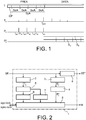
- each T frame comprises a preamble PREA followed by a DATA portion carrying a succession of data symbols.
- the training sequence SeA comprises Ns samples, for example 16 samples.
- the training symbol SA, as well as the data symbols, may be preceded by a cyclic prefix CP.
- the synchronization according to the invention is implemented once the gain adjustment phase has been completed.
- the method thus comprises a preliminary step of adjusting the gain of an amplifier of the receiver consisting in establishing a stationary gain setpoint. Once the stationary gain setpoint has been established, a time window is opened. During this window, the synchronization algorithm is activated. At the end of this window, if the synchronization is validated, the gain is maintained during the frame. Otherwise, the gain control unit takes over to carry out a new gain adjustment phase.
- the method according to the invention comprises the extraction of a correlation sequence from the training sequence.
- the correlation sequence thus corresponds to all or part of the training sequence and counts Ls samples (Ls ⁇ Ns).
- Ls Ns
- the method comprises determining a total correlation signal Tc and a partial correlation signal Pc.
- the total correlation signal Tc is determined by correlating the incoming signal with a correlation symbol formed of N repetitions of the correlation sequence.
- the correlation symbol corresponds to the training symbol SyA in the example considered where the correlation sequence corresponds precisely to the training sequence.
- the partial correlation signal Pc is determined from correlating the incoming signal with the correlation sequence (which precisely corresponds to the training sequence SeA in the example considered).
- the method is followed by a step of identifying a peak (a maximum) of the total correlation signal Tc at an instant t pct , called the date of the total correlation peak.
- a peak is considered good if the total correlation signal does not show a new maximum within a one-symbol window from the last maximum.
- At least at least one threshold is defined from the power of the peak of the total correlation signal.
- the method typically comprises defining, relative to the power of the peak of the total correlation signal, both a low threshold Sb and a high threshold Sh.
- the low threshold is a fraction of the power of the peak of the signal of total correlation
- the high threshold is a multiple of the peak power of the total correlation signal.
- the low threshold and the high threshold can be symmetrical with respect to the peak power of the total correlation signal. We can for example fix them respectively at -X dB and + X dB of the power of the peak of the total correlation signal, with X a strictly positive value.
- the method then comprises a step of comparing with the at least one threshold the power of the partial correlation signal Pc at the instants t pct -k * t sc preceding the date of the total correlation peak.
- the instants t pct -k * t sc are called partial correlation peak dates, t sc is the duration corresponding to the correlation sequence and k is an integer between 0 and N-1.
- the position of the peak of the total correlation signal effectively makes it possible to determine the relative positions of the peaks of the partial correlation signal, and the method proposes to analyze these positions to verify that they do indeed correspond to peaks.
- the partial correlation signal Pc is delayed. of a duration corresponds to the duration of the preamble PREA and form a delayed partial correlation signal Pc *.
- the position of the peak of the total correlation signal (at t pct ) makes it possible to predetermine the relative positions of the peaks of the delayed partial correlation signal (at t pct + t cp + m * t sc , where t cp corresponds to the duration of the cyclic prefix and m is an integer between 1 and N).
- the synchronization can be validated and the start time of the first symbol following the training symbol in the frame can be determined from the date of the total correlation peak.
- the synchronization is more precisely validated when the power of the partial correlation signal at each of the partial correlation peak dates is between the high threshold and the low threshold (i.e. we observe N peaks considered to be valid).
- the at least one threshold is determined relative to the power of the total correlation peak.
- the synchronization is made insensitive to inaccuracies in gain adjustment.
- the search for N valid peaks makes synchronization very robust in the unique presence of noise. Indeed, this plurality of valid peaks creates redundancy while it is unlikely that N “false” peaks have a power in the range of the low and high thresholds.
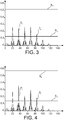
- Unit 1 receives an input data stream (incoming signal SE) and outputs an output signal SE * corresponds to the incoming signal SE delayed by means of a first timer 2 by a delay corresponding to the necessary duration synchronization calculations (this duration including in particular the analysis of the partial correlation signal delayed at the predetermined peak dates).
- Unit 1 further comprises a first correlator 2 configured to determine the total correlation signal Tc, a second correlator 3 configured to determine the partial correlation signal Pc and a second timer 4 configured to provide the delayed partial correlation signal Pc * .
- Unit 1 also includes a module 5 for analyzing the total correlation signal Tc configured to identify a maximum of the total correlation signal.
- This module 5 updates the maximum of the total correlation signal for each incoming sample.
- a threshold calculation module 6 is configured to calculate the at least one threshold Sb, Sh from the maximum of the total correlation signal updated at each incoming sample.
- a counter 8 is started for a duration corresponding to the duration of a symbol.
- a peak analysis module 9 comes to compare the power of the delayed partial correlation signal Pc * (on the peak dates predetermined by the identification of the new maximum, ie the launch date of the counter 8) with at least one threshold, and if necessary to the validation of the synchronization.
- the start time of the first symbol following the learning symbol in the frame is determined and the module 9 outputs a marker M for the start of the data packet DATA.
- the peak analysis module 9 is only activated during a time window launched following the establishment of a stationary gain setpoint by the gain control unit. Information for establishing the stationary setpoint agc-lock is therefore supplied to the module 9 by the gain control unit. If the synchronization is validated by the module 9 during its time window of activity, the gain is maintained during the frame. Otherwise, the gain control unit takes over to carry out a new gain adjustment phase. Information for validating the sync-lock synchronization is therefore supplied to the gain control unit by the module 9.
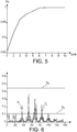
- the correlation sequence is identical to the training sequence and has 16 samples.
- the high and low thresholds are positioned within +/- 3 dB of the power of the total correlation peak. It is observed that for a signal to noise ratio greater than 7 dB, the detection is 100%. This value being in adequacy with the binary error curve of a QPSK modulation, the decoding of the data therefore stalls before the time synchronization deteriorates.
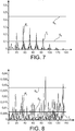
- FIG. 8 illustrates in this regard a case of false alarm.
- the highest power peak of the total correlation signal is at position 134 leading to an examination of the strength of the partial correlation signal at positions 134, 118, 102 and 84.
- the low threshold is set at 0.0071 and the high threshold at 0.0284 (+/- 3dB).
- the power of the partial correlation signal at the aforementioned positions is between the low and high thresholds, so that the synchronization is validated. However, these positions do not correspond to the peaks of the partial correlation signal and the validation of the synchronization is therefore erroneous.
- the method further comprises a step of invalidating the synchronization when the partial correlation signal is present, between the instants t pct -N * t sc and t pct and outside of time windows each comprising one of the partial correlation peak dates, a power greater than the power of the partial correlation signal at one of the partial correlation peak dates.
- time windows around the dates of the partial correlation peaks for example of three samples, ie the windows corresponding to positions [133-135], [117-119], [101-103] and [85-87]. It is checked whether in a window of duration 1 symbol (i.e. the positions in the range [62-134] by considering a symbol formed by a cyclic prefix of 8 samples and 4 repetitions of a training sequence of 16 samples), and outside the windows around the dates of the partial correlation peaks, there are partial correlation values higher than those leading to detection. This is the case in the example of figure 8 , and the synchronization is then disabled.
- the method comprises a step of invalidating the synchronization when the power of the partial correlation signal is at one. peak partial correlation dates is less than the strength of the total correlation signal at the peak total correlation date.
- the invention is not limited to the method described above but also extends to a receiver of a communication signal comprising means configured to implement the method, this receiver being able for example to be fitted with the synchronization unit. temporal of the figure 2 . And the invention also extends to a computer program product comprising code instructions. for the execution of the steps of the synchronization method when said program is executed on a computer.
Landscapes
- Engineering & Computer Science (AREA)
- Computer Networks & Wireless Communication (AREA)
- Signal Processing (AREA)
- Synchronisation In Digital Transmission Systems (AREA)
- Mobile Radio Communication Systems (AREA)
Claims (10)
- Verfahren zum Synchronisieren eines eingehenden Signals (SE) in einem Empfänger eines Kommunikationssystems, wobei das eingehenden Signal Datenrahmen trägt und jeder Rahmen (T) ein Trainingssymbol (SyA) umfasst, das aus N Wiederholungen einer Trainingssequenz (SeA) gebildet wird, wobei das Verfahren den folgenden Schritt umfasst:- Bestimmen eines Gesamtkorrelationssignals (Tc) durch Korrelieren des eingehenden Signals mit einem Korrelationssymbol, das aus N Wiederholungen einer Korrelationssequenz gebildet wird, die der gesamten oder einem Teil der Trainingssequenz entspricht;dadurch gekennzeichnet, dass es ferner die folgenden Schritte umfasst:- Bestimmen eines Teilkorrelationssignals (Pc) durch Korrelation des eingehenden Signals mit der Korrelationssequenz;- Identifizieren eines Spitzenwerts des Gesamtkorrelationssignals zu einem Zeitpunkt tpct, Zeitpunkt des Gesamtkorrelationsspitzenwerts genannt;- Festlegen mindestens eines Schwellenwerts (Sb, Sh) aus der Leistung des Spitzenwerts des Gesamtkorrelationssignals;- Vergleichen der Leistung des Teilkorrelationssignals mit dem mindestens einen Schwellenwert;- in Abhängigkeit vom Ergebnis dieses Vergleichs Validieren der Synchronisation und Bestimmen der Startzeit des ersten Symbols, das auf das Trainingssymbol im Rahmen folgt, anhand des Zeitpunkts des Gesamtkorrelationsspitzenwerts.
- Verfahren nach Anspruch 1, wobei das Vergleichen der Leistung des Teilkorrelationssignals mit dem mindestens einen Schwellenwert das Vergleichen der Leistung des Teilkorrelationssignals zu den Zeitpunkten tpct-k*tsc, die dem Zeitpunkt des Gesamtkorrelationsspitzenwerts vorausgehen, mit dem mindestens einen Schwellenwert umfasst, wobei die Zeitpunkte tpct-k*tsc die Zeitpunkte des Teilkorrelationsspitzenwertes sind und tsc die der Korrelationssequenz entsprechende Dauer ist und k eine ganze Zahl zwischen 0 und N-1 ist.
- Verfahren nach Anspruch 2, umfassend das Festlegen eines hohen Schwellenwerts (Sh) und eines niedrigen Schwellenwerts (Sb), wobei die Synchronisation validiert wird, wenn die Leistung des Teilkorrelationssignals zu jedem der Zeitpunkte des Teilkorrelationsspitzenwertes zwischen dem hohen Schwellenwert und dem niedrigen Schwellenwert liegt.
- Verfahren nach einem der Ansprüche 1 bis 3, wobei der niedrige Schwellenwert ein Bruchteil der Leistung des Spitzenwertes des Gesamtkorrelationssignals ist und der hohe Schwellenwert ein Vielfaches der Leistung des Spitzenwerts des Gesamtkorrelationssignals ist.
- Verfahren nach Anspruch 4, wobei der niedrige Schwellenwert und der hohe Schwellenwert symmetrisch in Bezug auf die Leistung des Spitzenwerts des Gesamtkorrelationssignals sind.
- Verfahren nach einem der Ansprüche 1 bis 5, ferner umfassend einen Schritt des Entvalidierens der Synchronisation, wenn das Teilkorrelationssignal zwischen den Zeitpunkten tpct-N*tsc und tpct und außerhalb von Zeitfenstern, die jeweils einen der Zeitpunkte des Teilkorrelationsspitzenwertes umfassen, eine Leistung aufweist, die höher ist als die Leistung des Teilkorrelationssignals an einem der Zeitpunkte des Teilkorrelationsspitzenwertes.
- Verfahren nach einem der Ansprüche 1 bis 6, ferner umfassend einen Schritt des Entvalidierens der Synchronisation, wenn die Leistung des Teilkorrelationssignals an einem der Zeitpunkte des Teilkorrelationsspitzenwertes niedriger ist als die Leistung des Gesamtkorrelationssignals zum Zeitpunkt des Gesamtkorrelationsspitzenwertes.
- Verfahren nach einem der Ansprüche 1 bis 6, umfassend einen vorherigen Schritt des Einstellens der Verstärkung eines Verstärkers des Empfängers durch Setzen eines stationären Verstärkungssollwerts.
- Empfänger für ein Kommunikationssignal, dadurch gekennzeichnet, dass er Mittel enthält, die dazu ausgelegt sind, um das Synchronisationsverfahren nach einem der Ansprüche 1 bis 7 durchzuführen.
- Computerprogrammprodukt mit Codeanweisungen zum Ausführen der Schritte des Verfahrens nach einem der Ansprüche 1 bis 7, wenn das Programm auf einem Computer ausgeführt wird.
Applications Claiming Priority (1)
| Application Number | Priority Date | Filing Date | Title |
|---|---|---|---|
| FR1759347A FR3072231B1 (fr) | 2017-10-05 | 2017-10-05 | Procede de synchronisation temporelle insensible aux variations de puissance, recepteur et programme d'ordinateur associes |
Publications (2)
| Publication Number | Publication Date |
|---|---|
| EP3468052A1 EP3468052A1 (de) | 2019-04-10 |
| EP3468052B1 true EP3468052B1 (de) | 2021-10-20 |
Family
ID=61223970
Family Applications (1)
| Application Number | Title | Priority Date | Filing Date |
|---|---|---|---|
| EP18197468.4A Active EP3468052B1 (de) | 2017-10-05 | 2018-09-28 | Zeitliches synchronisierungsverfahren, das gegenüber leistungsschwankungen unempfindlich ist, entsprechender empfänger und entsprechendes computerprogramm |
Country Status (3)
| Country | Link |
|---|---|
| US (1) | US10511431B2 (de) |
| EP (1) | EP3468052B1 (de) |
| FR (1) | FR3072231B1 (de) |
Families Citing this family (4)
| Publication number | Priority date | Publication date | Assignee | Title |
|---|---|---|---|---|
| GB2602683B (en) * | 2021-05-06 | 2023-03-08 | Nordic Semiconductor Asa | Radio receiver synchronization |
| EP4087176A3 (de) | 2021-05-06 | 2022-12-21 | Nordic Semiconductor ASA | Synchronisation von funkempfängern |
| WO2024116349A1 (ja) * | 2022-11-30 | 2024-06-06 | 三菱電機株式会社 | 受信装置及び検出決定方法 |
| US12537616B2 (en) * | 2023-06-02 | 2026-01-27 | Cypress Semiconductor Corporation | Frame synchronization detection with an adaptive threshold |
Family Cites Families (4)
| Publication number | Priority date | Publication date | Assignee | Title |
|---|---|---|---|---|
| DE4318368C1 (de) * | 1993-05-28 | 1994-07-14 | Siemens Ag | Verfahren zum Gewinnen eines einen Ausfall der Synchronisation zwischen einer Pseudozufallssignalfolge eines Senders und einer Referenz-Pseudozufallssignalfolge eines Empfängers anzeigenden Signals |
| US5598429A (en) * | 1994-07-15 | 1997-01-28 | Marshall; Kenneth E. | Multi-level correlation system for synchronization detection in high noise and multi-path environments |
| DE102006025042B4 (de) * | 2006-05-26 | 2008-08-14 | Infineon Technologies Ag | Datenratenfehler-tolerante Synchronisation eines digitalen Empfängers |
| KR101467234B1 (ko) * | 2013-11-19 | 2014-12-02 | 성균관대학교산학협력단 | 부분상관함수들의 단계적 조합에 기초한 cboc(6,1,1/11) 신호를 위한 비모호 상관함수 생성 방법, cboc 신호 추적 장치 및 이를 이용한 위성 항법 신호 수신 시스템 |
-
2017
- 2017-10-05 FR FR1759347A patent/FR3072231B1/fr active Active
-
2018
- 2018-09-28 EP EP18197468.4A patent/EP3468052B1/de active Active
- 2018-10-01 US US16/148,472 patent/US10511431B2/en active Active
Also Published As
| Publication number | Publication date |
|---|---|
| FR3072231A1 (fr) | 2019-04-12 |
| US10511431B2 (en) | 2019-12-17 |
| FR3072231B1 (fr) | 2021-04-30 |
| EP3468052A1 (de) | 2019-04-10 |
| US20190109698A1 (en) | 2019-04-11 |
Similar Documents
| Publication | Publication Date | Title |
|---|---|---|
| EP3468052B1 (de) | Zeitliches synchronisierungsverfahren, das gegenüber leistungsschwankungen unempfindlich ist, entsprechender empfänger und entsprechendes computerprogramm | |
| US7415059B2 (en) | Method and system for fast timing recovery for preamble based transmission systems | |
| RU2444841C2 (ru) | Обнаружение сигнала в системе беспроводной связи | |
| US6798738B1 (en) | FFT window position recovery apparatus and method for OFDM system receiver | |
| KR100234330B1 (ko) | Ofdm 시스템 수신기의 보호 구간 종류 검출장치 및 그 방법 | |
| KR101291859B1 (ko) | 변화하는 채널 조건에 대한 개선된 타이밍 획득 방법 및 시스템 | |
| EP0881804B1 (de) | Verfahren und System zur Bestimmung des Symbolübertragungsformats in einem Übertragungssystem | |
| WO2008009620A1 (fr) | Systeme d'estimation de la qualite de reception d'une transmission numerique | |
| US20060140293A1 (en) | Method for detecting signal and estimating symbol timing | |
| EP2425597B1 (de) | Verfahren zur blinden identifizierung eines ofdm siganls innerhalb eines von einem kommunikationssystem emfangenen gesamtsignals | |
| EP0643504A1 (de) | Schwellendetektor für CDMA System | |
| EP1330091B1 (de) | Verfahren zur Selektion einer Position eines FFT-Fensters in einem COFDM-Empfänger | |
| US9106498B2 (en) | Method for symbol synchronization of received digital signal and digital signal receiver using the same method | |
| FR2995749A1 (fr) | Procede de synchronisation d'un recepteur, procede de transmission d'un signal avec preambule et dispositifs correspondants, signal avec preambule correspondant | |
| US7616723B2 (en) | Method for symbol timing synchronization and apparatus thereof | |
| EP1081855B1 (de) | Verfahren und vorrichtung zur synchronisation eines kommunikationsempfängers | |
| EP2245786B1 (de) | Verfahren und vorrichtung zur ausrichtung eines datenstromes und nachrichtenübertragungssystem diese enthaltend | |
| US8594249B2 (en) | Device and method for detecting a useful signal by detecting a periodic signal contained in the useful signal | |
| EP3345357B1 (de) | Verfahren und einrichtung zur mimo-synchronization in der anwesenheit von interferenzen | |
| EP4290814B1 (de) | Verfahren und vorrichtung zur synchronisation eines digitalen funksignals | |
| FR2998973A1 (fr) | Procede de determination des caracteristiques d un signal radar en presence d interferences | |
| WO2026033185A1 (fr) | Procédé de traitement d'un signal reçu par un récepteur, le signal reçu étant issu de deux signaux à modulation de phase continue | |
| FR3072234A1 (fr) | Procede, systeme et programme d'ordinateur de surveillance d'une bande radiofrequences | |
| CA2404491A1 (fr) | Procede et dispositif de detection de sources dans un systeme de communications | |
| FR2751498A1 (fr) | Procede et dispositif de demodulation pour une transmission a sauts de frequence sur canal hf, en presence de brouillage |
Legal Events
| Date | Code | Title | Description |
|---|---|---|---|
| PUAI | Public reference made under article 153(3) epc to a published international application that has entered the european phase |
Free format text: ORIGINAL CODE: 0009012 |
|
| STAA | Information on the status of an ep patent application or granted ep patent |
Free format text: STATUS: REQUEST FOR EXAMINATION WAS MADE |
|
| 17P | Request for examination filed |
Effective date: 20180928 |
|
| AK | Designated contracting states |
Kind code of ref document: A1 Designated state(s): AL AT BE BG CH CY CZ DE DK EE ES FI FR GB GR HR HU IE IS IT LI LT LU LV MC MK MT NL NO PL PT RO RS SE SI SK SM TR |
|
| AX | Request for extension of the european patent |
Extension state: BA ME |
|
| GRAP | Despatch of communication of intention to grant a patent |
Free format text: ORIGINAL CODE: EPIDOSNIGR1 |
|
| STAA | Information on the status of an ep patent application or granted ep patent |
Free format text: STATUS: GRANT OF PATENT IS INTENDED |
|
| INTG | Intention to grant announced |
Effective date: 20210511 |
|
| GRAS | Grant fee paid |
Free format text: ORIGINAL CODE: EPIDOSNIGR3 |
|
| GRAA | (expected) grant |
Free format text: ORIGINAL CODE: 0009210 |
|
| STAA | Information on the status of an ep patent application or granted ep patent |
Free format text: STATUS: THE PATENT HAS BEEN GRANTED |
|
| AK | Designated contracting states |
Kind code of ref document: B1 Designated state(s): AL AT BE BG CH CY CZ DE DK EE ES FI FR GB GR HR HU IE IS IT LI LT LU LV MC MK MT NL NO PL PT RO RS SE SI SK SM TR |
|
| REG | Reference to a national code |
Ref country code: GB Ref legal event code: FG4D Free format text: NOT ENGLISH |
|
| REG | Reference to a national code |
Ref country code: CH Ref legal event code: EP |
|
| REG | Reference to a national code |
Ref country code: IE Ref legal event code: FG4D Free format text: LANGUAGE OF EP DOCUMENT: FRENCH |
|
| REG | Reference to a national code |
Ref country code: DE Ref legal event code: R096 Ref document number: 602018025231 Country of ref document: DE |
|
| REG | Reference to a national code |
Ref country code: AT Ref legal event code: REF Ref document number: 1440765 Country of ref document: AT Kind code of ref document: T Effective date: 20211115 |
|
| REG | Reference to a national code |
Ref country code: LT Ref legal event code: MG9D |
|
| REG | Reference to a national code |
Ref country code: NL Ref legal event code: MP Effective date: 20211020 |
|
| REG | Reference to a national code |
Ref country code: AT Ref legal event code: MK05 Ref document number: 1440765 Country of ref document: AT Kind code of ref document: T Effective date: 20211020 |
|
| PG25 | Lapsed in a contracting state [announced via postgrant information from national office to epo] |
Ref country code: RS Free format text: LAPSE BECAUSE OF FAILURE TO SUBMIT A TRANSLATION OF THE DESCRIPTION OR TO PAY THE FEE WITHIN THE PRESCRIBED TIME-LIMIT Effective date: 20211020 Ref country code: LT Free format text: LAPSE BECAUSE OF FAILURE TO SUBMIT A TRANSLATION OF THE DESCRIPTION OR TO PAY THE FEE WITHIN THE PRESCRIBED TIME-LIMIT Effective date: 20211020 Ref country code: FI Free format text: LAPSE BECAUSE OF FAILURE TO SUBMIT A TRANSLATION OF THE DESCRIPTION OR TO PAY THE FEE WITHIN THE PRESCRIBED TIME-LIMIT Effective date: 20211020 Ref country code: BG Free format text: LAPSE BECAUSE OF FAILURE TO SUBMIT A TRANSLATION OF THE DESCRIPTION OR TO PAY THE FEE WITHIN THE PRESCRIBED TIME-LIMIT Effective date: 20220120 Ref country code: AT Free format text: LAPSE BECAUSE OF FAILURE TO SUBMIT A TRANSLATION OF THE DESCRIPTION OR TO PAY THE FEE WITHIN THE PRESCRIBED TIME-LIMIT Effective date: 20211020 |
|
| PG25 | Lapsed in a contracting state [announced via postgrant information from national office to epo] |
Ref country code: IS Free format text: LAPSE BECAUSE OF FAILURE TO SUBMIT A TRANSLATION OF THE DESCRIPTION OR TO PAY THE FEE WITHIN THE PRESCRIBED TIME-LIMIT Effective date: 20220220 Ref country code: SE Free format text: LAPSE BECAUSE OF FAILURE TO SUBMIT A TRANSLATION OF THE DESCRIPTION OR TO PAY THE FEE WITHIN THE PRESCRIBED TIME-LIMIT Effective date: 20211020 Ref country code: PT Free format text: LAPSE BECAUSE OF FAILURE TO SUBMIT A TRANSLATION OF THE DESCRIPTION OR TO PAY THE FEE WITHIN THE PRESCRIBED TIME-LIMIT Effective date: 20220221 Ref country code: PL Free format text: LAPSE BECAUSE OF FAILURE TO SUBMIT A TRANSLATION OF THE DESCRIPTION OR TO PAY THE FEE WITHIN THE PRESCRIBED TIME-LIMIT Effective date: 20211020 Ref country code: NO Free format text: LAPSE BECAUSE OF FAILURE TO SUBMIT A TRANSLATION OF THE DESCRIPTION OR TO PAY THE FEE WITHIN THE PRESCRIBED TIME-LIMIT Effective date: 20220120 Ref country code: NL Free format text: LAPSE BECAUSE OF FAILURE TO SUBMIT A TRANSLATION OF THE DESCRIPTION OR TO PAY THE FEE WITHIN THE PRESCRIBED TIME-LIMIT Effective date: 20211020 Ref country code: LV Free format text: LAPSE BECAUSE OF FAILURE TO SUBMIT A TRANSLATION OF THE DESCRIPTION OR TO PAY THE FEE WITHIN THE PRESCRIBED TIME-LIMIT Effective date: 20211020 Ref country code: HR Free format text: LAPSE BECAUSE OF FAILURE TO SUBMIT A TRANSLATION OF THE DESCRIPTION OR TO PAY THE FEE WITHIN THE PRESCRIBED TIME-LIMIT Effective date: 20211020 Ref country code: GR Free format text: LAPSE BECAUSE OF FAILURE TO SUBMIT A TRANSLATION OF THE DESCRIPTION OR TO PAY THE FEE WITHIN THE PRESCRIBED TIME-LIMIT Effective date: 20220121 Ref country code: ES Free format text: LAPSE BECAUSE OF FAILURE TO SUBMIT A TRANSLATION OF THE DESCRIPTION OR TO PAY THE FEE WITHIN THE PRESCRIBED TIME-LIMIT Effective date: 20211020 |
|
| REG | Reference to a national code |
Ref country code: DE Ref legal event code: R097 Ref document number: 602018025231 Country of ref document: DE |
|
| PG25 | Lapsed in a contracting state [announced via postgrant information from national office to epo] |
Ref country code: SM Free format text: LAPSE BECAUSE OF FAILURE TO SUBMIT A TRANSLATION OF THE DESCRIPTION OR TO PAY THE FEE WITHIN THE PRESCRIBED TIME-LIMIT Effective date: 20211020 Ref country code: SK Free format text: LAPSE BECAUSE OF FAILURE TO SUBMIT A TRANSLATION OF THE DESCRIPTION OR TO PAY THE FEE WITHIN THE PRESCRIBED TIME-LIMIT Effective date: 20211020 Ref country code: RO Free format text: LAPSE BECAUSE OF FAILURE TO SUBMIT A TRANSLATION OF THE DESCRIPTION OR TO PAY THE FEE WITHIN THE PRESCRIBED TIME-LIMIT Effective date: 20211020 Ref country code: EE Free format text: LAPSE BECAUSE OF FAILURE TO SUBMIT A TRANSLATION OF THE DESCRIPTION OR TO PAY THE FEE WITHIN THE PRESCRIBED TIME-LIMIT Effective date: 20211020 Ref country code: DK Free format text: LAPSE BECAUSE OF FAILURE TO SUBMIT A TRANSLATION OF THE DESCRIPTION OR TO PAY THE FEE WITHIN THE PRESCRIBED TIME-LIMIT Effective date: 20211020 Ref country code: CZ Free format text: LAPSE BECAUSE OF FAILURE TO SUBMIT A TRANSLATION OF THE DESCRIPTION OR TO PAY THE FEE WITHIN THE PRESCRIBED TIME-LIMIT Effective date: 20211020 |
|
| PLBE | No opposition filed within time limit |
Free format text: ORIGINAL CODE: 0009261 |
|
| STAA | Information on the status of an ep patent application or granted ep patent |
Free format text: STATUS: NO OPPOSITION FILED WITHIN TIME LIMIT |
|
| 26N | No opposition filed |
Effective date: 20220721 |
|
| PG25 | Lapsed in a contracting state [announced via postgrant information from national office to epo] |
Ref country code: AL Free format text: LAPSE BECAUSE OF FAILURE TO SUBMIT A TRANSLATION OF THE DESCRIPTION OR TO PAY THE FEE WITHIN THE PRESCRIBED TIME-LIMIT Effective date: 20211020 |
|
| PG25 | Lapsed in a contracting state [announced via postgrant information from national office to epo] |
Ref country code: SI Free format text: LAPSE BECAUSE OF FAILURE TO SUBMIT A TRANSLATION OF THE DESCRIPTION OR TO PAY THE FEE WITHIN THE PRESCRIBED TIME-LIMIT Effective date: 20211020 |
|
| PG25 | Lapsed in a contracting state [announced via postgrant information from national office to epo] |
Ref country code: MC Free format text: LAPSE BECAUSE OF FAILURE TO SUBMIT A TRANSLATION OF THE DESCRIPTION OR TO PAY THE FEE WITHIN THE PRESCRIBED TIME-LIMIT Effective date: 20211020 |
|
| REG | Reference to a national code |
Ref country code: CH Ref legal event code: PL |
|
| REG | Reference to a national code |
Ref country code: BE Ref legal event code: MM Effective date: 20220930 |
|
| PG25 | Lapsed in a contracting state [announced via postgrant information from national office to epo] |
Ref country code: IT Free format text: LAPSE BECAUSE OF FAILURE TO SUBMIT A TRANSLATION OF THE DESCRIPTION OR TO PAY THE FEE WITHIN THE PRESCRIBED TIME-LIMIT Effective date: 20211020 |
|
| PG25 | Lapsed in a contracting state [announced via postgrant information from national office to epo] |
Ref country code: LU Free format text: LAPSE BECAUSE OF NON-PAYMENT OF DUE FEES Effective date: 20220928 |
|
| PG25 | Lapsed in a contracting state [announced via postgrant information from national office to epo] |
Ref country code: LI Free format text: LAPSE BECAUSE OF NON-PAYMENT OF DUE FEES Effective date: 20220930 Ref country code: IE Free format text: LAPSE BECAUSE OF NON-PAYMENT OF DUE FEES Effective date: 20220928 Ref country code: CH Free format text: LAPSE BECAUSE OF NON-PAYMENT OF DUE FEES Effective date: 20220930 |
|
| PG25 | Lapsed in a contracting state [announced via postgrant information from national office to epo] |
Ref country code: BE Free format text: LAPSE BECAUSE OF NON-PAYMENT OF DUE FEES Effective date: 20220930 |
|
| PG25 | Lapsed in a contracting state [announced via postgrant information from national office to epo] |
Ref country code: HU Free format text: LAPSE BECAUSE OF FAILURE TO SUBMIT A TRANSLATION OF THE DESCRIPTION OR TO PAY THE FEE WITHIN THE PRESCRIBED TIME-LIMIT; INVALID AB INITIO Effective date: 20180928 |
|
| PG25 | Lapsed in a contracting state [announced via postgrant information from national office to epo] |
Ref country code: CY Free format text: LAPSE BECAUSE OF FAILURE TO SUBMIT A TRANSLATION OF THE DESCRIPTION OR TO PAY THE FEE WITHIN THE PRESCRIBED TIME-LIMIT Effective date: 20211020 |
|
| PG25 | Lapsed in a contracting state [announced via postgrant information from national office to epo] |
Ref country code: MK Free format text: LAPSE BECAUSE OF FAILURE TO SUBMIT A TRANSLATION OF THE DESCRIPTION OR TO PAY THE FEE WITHIN THE PRESCRIBED TIME-LIMIT Effective date: 20211020 |
|
| PG25 | Lapsed in a contracting state [announced via postgrant information from national office to epo] |
Ref country code: TR Free format text: LAPSE BECAUSE OF FAILURE TO SUBMIT A TRANSLATION OF THE DESCRIPTION OR TO PAY THE FEE WITHIN THE PRESCRIBED TIME-LIMIT Effective date: 20211020 |
|
| PG25 | Lapsed in a contracting state [announced via postgrant information from national office to epo] |
Ref country code: MT Free format text: LAPSE BECAUSE OF FAILURE TO SUBMIT A TRANSLATION OF THE DESCRIPTION OR TO PAY THE FEE WITHIN THE PRESCRIBED TIME-LIMIT Effective date: 20211020 |
|
| PGFP | Annual fee paid to national office [announced via postgrant information from national office to epo] |
Ref country code: DE Payment date: 20240919 Year of fee payment: 7 |
|
| PGFP | Annual fee paid to national office [announced via postgrant information from national office to epo] |
Ref country code: GB Payment date: 20240923 Year of fee payment: 7 |
|
| PGFP | Annual fee paid to national office [announced via postgrant information from national office to epo] |
Ref country code: FR Payment date: 20240917 Year of fee payment: 7 |