EP3467943A1 - Clip for grounding - Google Patents
Clip for grounding Download PDFInfo
- Publication number
- EP3467943A1 EP3467943A1 EP17806250.1A EP17806250A EP3467943A1 EP 3467943 A1 EP3467943 A1 EP 3467943A1 EP 17806250 A EP17806250 A EP 17806250A EP 3467943 A1 EP3467943 A1 EP 3467943A1
- Authority
- EP
- European Patent Office
- Prior art keywords
- grounding
- grommet
- elastic
- clip
- grommet member
- Prior art date
- Legal status (The legal status is an assumption and is not a legal conclusion. Google has not performed a legal analysis and makes no representation as to the accuracy of the status listed.)
- Granted
Links
Images






Classifications
-
- H—ELECTRICITY
- H01—ELECTRIC ELEMENTS
- H01R—ELECTRICALLY-CONDUCTIVE CONNECTIONS; STRUCTURAL ASSOCIATIONS OF A PLURALITY OF MUTUALLY-INSULATED ELECTRICAL CONNECTING ELEMENTS; COUPLING DEVICES; CURRENT COLLECTORS
- H01R4/00—Electrically-conductive connections between two or more conductive members in direct contact, i.e. touching one another; Means for effecting or maintaining such contact; Electrically-conductive connections having two or more spaced connecting locations for conductors and using contact members penetrating insulation
- H01R4/58—Electrically-conductive connections between two or more conductive members in direct contact, i.e. touching one another; Means for effecting or maintaining such contact; Electrically-conductive connections having two or more spaced connecting locations for conductors and using contact members penetrating insulation characterised by the form or material of the contacting members
- H01R4/64—Connections between or with conductive parts having primarily a non-electric function, e.g. frame, casing, rail
-
- B—PERFORMING OPERATIONS; TRANSPORTING
- B60—VEHICLES IN GENERAL
- B60K—ARRANGEMENT OR MOUNTING OF PROPULSION UNITS OR OF TRANSMISSIONS IN VEHICLES; ARRANGEMENT OR MOUNTING OF PLURAL DIVERSE PRIME-MOVERS IN VEHICLES; AUXILIARY DRIVES FOR VEHICLES; INSTRUMENTATION OR DASHBOARDS FOR VEHICLES; ARRANGEMENTS IN CONNECTION WITH COOLING, AIR INTAKE, GAS EXHAUST OR FUEL SUPPLY OF PROPULSION UNITS IN VEHICLES
- B60K15/00—Arrangement in connection with fuel supply of combustion engines or other fuel consuming energy converters, e.g. fuel cells; Mounting or construction of fuel tanks
- B60K15/03—Fuel tanks
- B60K15/04—Tank inlets
- B60K15/05—Inlet covers
-
- H—ELECTRICITY
- H01—ELECTRIC ELEMENTS
- H01R—ELECTRICALLY-CONDUCTIVE CONNECTIONS; STRUCTURAL ASSOCIATIONS OF A PLURALITY OF MUTUALLY-INSULATED ELECTRICAL CONNECTING ELEMENTS; COUPLING DEVICES; CURRENT COLLECTORS
- H01R4/00—Electrically-conductive connections between two or more conductive members in direct contact, i.e. touching one another; Means for effecting or maintaining such contact; Electrically-conductive connections having two or more spaced connecting locations for conductors and using contact members penetrating insulation
- H01R4/58—Electrically-conductive connections between two or more conductive members in direct contact, i.e. touching one another; Means for effecting or maintaining such contact; Electrically-conductive connections having two or more spaced connecting locations for conductors and using contact members penetrating insulation characterised by the form or material of the contacting members
- H01R4/66—Connections with the terrestrial mass, e.g. earth plate, earth pin
-
- H—ELECTRICITY
- H01—ELECTRIC ELEMENTS
- H01R—ELECTRICALLY-CONDUCTIVE CONNECTIONS; STRUCTURAL ASSOCIATIONS OF A PLURALITY OF MUTUALLY-INSULATED ELECTRICAL CONNECTING ELEMENTS; COUPLING DEVICES; CURRENT COLLECTORS
- H01R11/00—Individual connecting elements providing two or more spaced connecting locations for conductive members which are, or may be, thereby interconnected, e.g. end pieces for wires or cables supported by the wire or cable and having means for facilitating electrical connection to some other wire, terminal, or conductive member, blocks of binding posts
- H01R11/11—End pieces or tapping pieces for wires, supported by the wire and for facilitating electrical connection to some other wire, terminal or conductive member
- H01R11/12—End pieces terminating in an eye, hook, or fork
-
- H—ELECTRICITY
- H01—ELECTRIC ELEMENTS
- H01R—ELECTRICALLY-CONDUCTIVE CONNECTIONS; STRUCTURAL ASSOCIATIONS OF A PLURALITY OF MUTUALLY-INSULATED ELECTRICAL CONNECTING ELEMENTS; COUPLING DEVICES; CURRENT COLLECTORS
- H01R13/00—Details of coupling devices of the kinds covered by groups H01R12/70 or H01R24/00 - H01R33/00
- H01R13/73—Means for mounting coupling parts to apparatus or structures, e.g. to a wall
- H01R13/74—Means for mounting coupling parts in openings of a panel
-
- H—ELECTRICITY
- H01—ELECTRIC ELEMENTS
- H01R—ELECTRICALLY-CONDUCTIVE CONNECTIONS; STRUCTURAL ASSOCIATIONS OF A PLURALITY OF MUTUALLY-INSULATED ELECTRICAL CONNECTING ELEMENTS; COUPLING DEVICES; CURRENT COLLECTORS
- H01R2201/00—Connectors or connections adapted for particular applications
- H01R2201/26—Connectors or connections adapted for particular applications for vehicles
Definitions
- the present invention relates to a clip for grounding.
- a terminal for grounding made of carbon fiber-reinforced plastic comprising an insertion portion to be inserted into an opening of a reference potential member while contracting by an elastic deformation; and an engagement portion engaging the opening by an elastic return after an insertion, there is a terminal for grounding shown in Patent Document 1.
- the terminal for grounding of the Patent Document 1 merely links an insulated wire to a reference potential member. Also, since the terminal for grounding is made of plastic, an elastic force thereof is not permanently maintained. Plastic products easily cause a reduction of the elastic force by a creep deformation especially under a high temperature and high stress. In a case wherein the elastic force of the terminal for grounding is reduced, an engagement state with the reference potential member, i.e., an electrical connection state between the insulated wire and the reference potential member is damaged.
- Patent Document 1 Japanese Unexamined Patent Application Publication No. 2013-222527
- a main object of the present invention is to appropriately provide a function of linking a grounding processing object to a nonconductive attachment object, and in association with this linking, a function of electrically connecting the grounding processing object to a reference potential member, in this type of clip for grounding.
- a clip for grounding comprises a grommet member made of a conductive resin, electrically connected to a grounding processing object, and fitted into an attachment hole formed in a nonconductive attachment object so as to link the grounding processing object to the attachment object; and a contact member made of metal, combined with the grommet member, and provided with an elastic contact portion relative to a reference potential member positioned on a fitting tip side of the grommet member.
- the grounding processing object can be appropriately electrically connected to the reference potential member through the clip for grounding.
- the elastic contact portion is formed by one portion of the contact member made of metal, so that an elastic deformation force is difficult to be lost over time, and the elastic contact portion continues to contact the reference potential member with a fixed elastic force.
- the elastic contact portion can contact the reference potential member, for example, a body panel of an automobile with the fixed elastic force, even in a case wherein there is a slight error in a positional relationship between the attachment hole and a portion which becomes a contact point of the reference potential member, the aforementioned error is absorbed so as to contact the elastic contact portion with the reference potential member.
- the grommet member includes wall portions respectively on both sides sandwiching a center portion; the contact member includes a pair of elastic engagement pieces to be inserted into an insertion gap formed between the center portion and the wall portions from a tip side of the grommet member; and by an elastic return of the elastic engagement piece at an insertion end position into the insertion gap, an engagement portion of the elastic engagement piece engages an exit portion of the insertion gap.
- the contact member includes a pair of elastic clamping pieces to be inserted into the insertion gap from the tip side of the grommet member; and in a state wherein the center portion is clamped between the pair of elastic clamping pieces, the contact member is combined with the grommet member.
- the center portion of the grommet member has a cylindrical shape in which the tip side of the grommet member is closed, and a base portion side is open;
- the clip for grounding includes a pin member to be fitted into the center portion from the base portion side; and the pin member inserted to pass through a hole formed in one portion of the grounding processing object fits into the center portion so as to electrically connect the grounding processing object and the grommet member.
- the grommet member includes a flange on the base portion side, and is provided with a packing member for sealing fluid-tightly between the flange and the attachment hole.
- the grounding processing object is a cap of a fuel filling aperture of the automobile, and a conductive tether connected to the cap;
- the attachment object is a fuel-filling-aperture forming member wherein an inside thereof is an insertion space for a fueling gun;
- the reference potential member is the body panel of the automobile; and by the clip for grounding, the cap is connected to the fuel-filling-aperture forming member side in a grounding processing state.
- the function of linking the grounding processing object to the nonconductive attachment object, and in association with this linking, the function of electrically connecting the grounding processing object to the reference potential member, can be appropriately provided in the clip for grounding.
- a clip for grounding has a function of linking a grounding processing object 1 to a nonconductive attachment object 2 shown in Fig. 21 to Fig. 22 , and also in association with this linking, a function of electrically connecting the grounding processing object 1 to a reference potential member 3 shown in Fig. 21 to Fig. 22 .
- Fig. 21 shows an example wherein the grounding processing object 1 is a cap (not shown in the drawings) of a fuel filling aperture of an automobile, and a conductive tether 1a connected to the cap; the attachment object 2 is a fuel-filling-aperture forming member 2a wherein an inside thereof is an insertion space 2b for a fueling gun; and the reference potential member 3 is a body panel 3a of the automobile.
- the grounding processing object 1 is a cap (not shown in the drawings) of a fuel filling aperture of an automobile, and a conductive tether 1a connected to the cap
- the attachment object 2 is a fuel-filling-aperture forming member 2a wherein an inside thereof is an insertion space 2b for a fueling gun
- the reference potential member 3 is a body panel 3a of the automobile.
- the fuel-filling-aperture forming member 2a is formed of a nonconductive synthetic resin
- the clip for grounding is connected to the cap through the tether 1a, and an elastic contact portion 50 of the later-described contact member 5 contacts the body panel 3a positioned on an inner face side of the fuel-filling-aperture forming member 2a, so that the cap is connected to the fuel-filling-aperture forming member 2a in a state wherein grounding processing is carried out.
- the later-described pin member 6 inserted to pass through a hole 1b formed in one end portion of the tether 1a as one portion of the grounding processing object 1 fits into a center portion 41a (see Fig. 10 ) of the later-described grommet member 4 so as to electrically connect the grounding processing object 1 and the grommet member 4.
- the cap connected to the other end portion of the tether 1a around the pin member 6 is connected to the fuel-filling-aperture forming member 2a in a turnable state.
- the clip for grounding is formed by the grommet member 4, the contact member 5, the pin member 6, and a packing member 7.
- the grommet member 4 is made of a conductive resin.
- the pin member 6 is typically formed of a material having a conductive property as well, and it is typically preferably made of the conductive resin.
- the contact member 5 is made of metal, and has the conductive property.
- the grommet member 4 is electrically connected to the grounding processing object 1, and fits into an attachment hole 2c formed in the nonconductive attachment object 2 so as to have a structure of linking the grounding processing object 1 to the attachment object 2.
- the grommet member 4 comprises a disk-shaped head portion 40, and a fitting portion 41 into the attachment hole 2c.
- the head portion 40 has a size which does not enter into the attachment hole 2c.
- the grommet member 4 comprises a flange 42 forming an outer flange shape on a base portion 44 side thereof.
- the head portion 40 and the fitting portion 41 are integrated on one face side of the head portion 40.
- the fitting portion 41 includes the center portion 41a, a wall portion 41g, and an insertion gap 41h formed between the center portion 41a and the wall portions 41g.
- the center portion 41a has a cylindrical shape in which a tip 43 side of the grommet member 4, i.e., a side which becomes an insertion side of the grommet member 4 relative to the attachment hole 2c, is closed, and the base portion 44 side which is opposite to the tip 43 side, is open.
- the center portion 41a is integrated with the head portion 40 on the base portion 44 side.
- the center portion 41a has a rectangular cylindrical shape wherein an outline shape in cross section in a direction orthogonal to a fitting direction x (see Fig. 5 ) is a rectangle.
- an insertion hole 40a of the pin member 6 see Fig. 1
- the insertion hole 40a communicates with an inside of the center portion 41a.
- the center portion 41a opens only on the base portion 44 side of the grommet member 4, in a state wherein the tether 1a as one portion of the grounding processing object 1 is attached to the fuel-filling-aperture forming member 2a as the attachment object 2, rainwater and the like do not enter into a vehicle inside of the automobile through the center portion 41a of the grommet member 4.
- rib-shaped portions 41c projecting in a direction orthogonal to a long-side side face portions 41b of the center portion 41a.
- the wall portions 41g are respectively formed on an outside of two long-side side face portions 41b of the center portion 41a.
- the wall portion 41g has a band plate shape provided between the rib-shaped portions 41c and 41c positioned on both sides of one long-side side face portion 41b.
- the wall portion 41g is provided in a position between the tip 43 and the base portion 44 of the grommet member 4.
- an exit portion 41i of the insertion gap 41h by an edge portion facing the base portion 44 side of the grommet member 4 in the wall portion 41g.
- an entrance portion 41j of the insertion gap 41h is formed by an edge portion facing the tip 43 side of the grommet member 4 in the wall portion 41g.
- engagement portions 41d engaging the attachment holes 2c on an insertion tip side, i.e., a fitting tip side Fw (see Fig. 21 ) when the grommet member 4 is inserted into the attachment hole 2c.
- the engagement portion 41d is formed by an elastic piece projecting toward the head portion 40 side from the edge portion facing the base portion 44 side of the grommet member 4 in the wall portion 41g.
- An inner face of the elastic piece is positioned on a face same as an inner face of the wall portion 41g.
- an outer face of the elastic piece becomes an inclined face 41e gradually increasing a thickness of the elastic piece as separating from a connection side to the wall portion 41g.
- the engagement portion 41d is formed on one side sandwiching a straight line y (see Fig. 5 ) substantially dividing the long-side side face portion 41b of the center portion 41a into two to the right and left along the fitting direction x.
- the exit portion 41i of the insertion gap 41h is formed on the other side sandwiching the straight line y.
- the engagement portion 41d and the exit portion 41i formed on the outside of one of the two long-side side face portions 41b and 41b are disposed in a point-symmetry position around a shaft center z (see Fig. 14 ) of the center portion 41a.
- the attachment hole 2c comprises a rectangular main hole portion 2d following the outline shape in cross section of the center portion 41a of the fitting portion 41; and a concave portion 2e formed at an intermediate position of one of two width-side hole edge portions of the main hole portion 2d.
- a distance between two length-side hole edge portions 2f and 2f of the main hole portion 2d is slightly smaller than a distance between the outer faces of the elastic pieces forming the two engagement portions 41d and 41d of the grommet member 4 on the base portion 44 side.
- a distance between the head portion 40 of the grommet member 4 and an end portion of the elastic piece forming the engagement portion 41d on the base portion 44 side is substantially equal to a thickness of the fuel-filling-aperture forming member 2a at a portion forming the attachment hole 2c.
- the grommet member 4 when the grommet member 4 is inserted into the attachment hole 2c from a vehicle outside of the automobile, the aforementioned insertion is allowed while bending the elastic pieces forming the two engagement portions 41d inwardly, and by a bending return of the elastic piece forming the engagement portion 41d at an insertion end position, the elastic piece forming the engagement portion 41d and the head portion 40 sandwich the portion forming the attachment hole 2c therebetween from the inside and outside, thereby fitting the grommet member 4 into the attachment hole 2c.
- the contact member 5 is combined with the grommet member 4, and is formed by comprising the elastic contact portion 50 relative to the reference potential member 3 positioned on the fitting tip side Fw of the grommet member 4 (see Fig. 1 and Fig. 2 ).
- the contact member 5 includes a pair of elastic engagement pieces 51 and 51 to be inserted into the insertion gaps 41h formed between the center portion 41a and the wall portions 41g from the tip 43 side of the grommet member 4 (see Fig. 9 ). Then, the contact member 5 engages engagement portions 51b of the elastic engagement pieces 51 with the exit portion 41i of the insertion gaps 41h by an elastic return of the elastic engagement pieces 51 at an insertion end position into the insertion gaps 41h (see Fig. 10 ).
- the contact member 5 includes a pair of elastic clamping pieces 52 and 52 to be inserted into the insertion gaps 41h from the tip 43 side of the grommet member 4. Then, the contact member 5 is combined with the grommet member 4 in a state wherein the center portion 41a is clamped between the pair of elastic clamping pieces 52 and 52.
- the contact member 5 is formed by cutting and folding a metal plate.
- the contact member 5 includes a base plate portion 53 having substantially a rectangular shape.
- a base portion side of the elastic contact portion 50 having a band plate shape is integrally connected to one of two width-side side portions 53a and 53a of the base plate portion 53, and the elastic contact portion 50 has an arm shape projecting from the base plate portion 53.
- the elastic contact portion 50 projects in such a way so as to have an inclination which gradually increases a distance to the width-side side portion 53a of the base plate portion 53 as coming close to a tip thereof.
- the tip of the elastic contact portion 50 is folded on a width-side side portion 53a side of the base plate portion 53, and on an outside opposite to a side facing the base plate portion 53 in the elastic contact portion 50, there is formed a shoulder portion 50a by the aforementioned folding.
- the contact member 5 comprises two rising portions 54 and 54 rising in a direction substantially orthogonal to the base plate portion 53 by bending two length-side side portions 53b and 53b of the base plate portion 53 as a bending portion (see Fig. 18 ).
- the two rising portions 54 and 54 there are respectively formed division grooves 55 leading to an approximately middle position in a rising direction from a tip thereof, and by the division grooves 55, the elastic engagement pieces 51 and the elastic clamping pieces 52 are formed respectively in the two rising portions 54 and 54.
- the elastic engagement piece 51 and the elastic clamping piece 52 formed on one side of the two length-side side portions 53b of the base plate portion 53 are disposed in a point-symmetry position around a center z' (see Fig. 17 ) of the base plate portion 53.
- the pair of elastic engagement pieces 51 and 51 has an embodiment gradually increasing a distance between the pair of elastic engagement pieces 51 and 51 as coming close to bending portions which become the engagement portions 51b formed on roughly an upper end side thereof.
- Upper sides relative to the bending portions which become the engagement portions 51b of the elastic engagement pieces 51 become insertion guide portions 51a inclining toward a direction of gradually reducing the distance between the pair of elastic engagement pieces 51 and 51.
- the pair of elastic clamping pieces 52 and 52 has a structure gradually reducing a distance between the pair of elastic clamping pieces 52 and 52 as coming close to roughly a tip thereof.
- the pair of elastic clamping pieces 52 and 52 clamps the center portion 41a by respectively sliding to contact the long-side side face portions 41b of the center portion 41a.
- the pair of elastic engagement pieces 51 and 51 respectively inserts the insertion guide portions 51a into the insertion gaps 41h without being caught on the entrance portions 41j of the insertion gaps 41h.
- the grommet member 4 and the contact member 5 are appropriately electrically connected by the elastic engagement piece 51 and the elastic clamping piece 52.
- the elastic contact portion 50 advances to the fitting tip side Fw of the attachment hole 2c through the concave portion 2e.
- the elastic contact portion 50 advanced in the aforementioned manner contacts relative to an edge portion of the body panel 3a positioned on a vehicle inside of the fuel-filling-aperture forming member 2a in a state slightly elastically deformed in a direction of coming close to the base plate portion 53.
- the tether 1a and the cap as the grounding processing object 1 can be appropriately electrically connected to the reference potential member 3 through the clip for grounding. Since the elastic contact portion 50 is formed by one portion of the contact member 5 made of metal, an elastic deformation force is difficult to be lost over time, and the elastic contact portion 50 continues to contact the body panel 3a as the reference potential member 3 with a fixed elastic force.
- the elastic contact portion 50 can contact the body panel 3a as the reference potential member 3 with the fixed elastic force, even in a case wherein there is a slight error in a positional relationship between the attachment hole 2c and a portion 3b which becomes a contact point for grounding the body panel 3a as the reference potential member 3, the aforementioned error is absorbed so as to contact the elastic contact portion 50 with the body panel 3a as the reference potential member 3.
- the elastic contact portion 50 passes the concave portion 2e while elastically deforming in the direction of coming close to the base plate portion 53, and comes out of the fuel-filling-aperture forming member 2a as the attachment object 2 together with the grommet member 4 without separating from the grommet member 4.
- the pin member 6 has a structure comprising a disk-shaped head portion 6a and a shaft portion 6b projecting from a center of one face side of the head portion 6a. There is formed a constriction portion 6c between a tip and a base portion of the shaft portion 6b. As shown in Fig. 13 , inside the center portion 41a of the grommet member 4, there is formed a protrusion portion 41f relative to the constriction portion 6c.
- the tip of the pin member 6 abuts against the protrusion portion 41f, and the center portion 41a elastically deforms to allow an insertion of the pin member 6 further inside.
- the packing member 7 has a structure of sealing fluid-tightly between the flange 42 formed by the head portion 40 of the grommet member 4 and the attachment hole 2c.
- the packing member 7 includes a through hole 7a for the grommet member 4, which follows the outline shape in cross section of the center portion 41a, and is provided in the grommet member 4 in such a way so as to contact one surface thereof with the flange 42 by passing the fitting portion 41 of the grommet member 4 through the through hole 7a.
- the present invention is not limited to the embodiment explained hereinabove, and includes all embodiments which can obtain the object of the present invention.
Landscapes
- Engineering & Computer Science (AREA)
- Transportation (AREA)
- Sustainable Development (AREA)
- Sustainable Energy (AREA)
- Chemical & Material Sciences (AREA)
- Combustion & Propulsion (AREA)
- Life Sciences & Earth Sciences (AREA)
- Mechanical Engineering (AREA)
- Insertion Pins And Rivets (AREA)
- Installation Of Indoor Wiring (AREA)
- Multi-Conductor Connections (AREA)
- Cooling, Air Intake And Gas Exhaust, And Fuel Tank Arrangements In Propulsion Units (AREA)
- Elimination Of Static Electricity (AREA)
Abstract
Description
- The present invention relates to a clip for grounding.
- As for a terminal for grounding made of carbon fiber-reinforced plastic comprising an insertion portion to be inserted into an opening of a reference potential member while contracting by an elastic deformation; and an engagement portion engaging the opening by an elastic return after an insertion, there is a terminal for grounding shown in Patent Document 1.
- However, the terminal for grounding of the Patent Document 1 merely links an insulated wire to a reference potential member. Also, since the terminal for grounding is made of plastic, an elastic force thereof is not permanently maintained. Plastic products easily cause a reduction of the elastic force by a creep deformation especially under a high temperature and high stress. In a case wherein the elastic force of the terminal for grounding is reduced, an engagement state with the reference potential member, i.e., an electrical connection state between the insulated wire and the reference potential member is damaged.
- Patent Document 1: Japanese Unexamined Patent Application Publication No.
2013-222527 - A main object of the present invention is to appropriately provide a function of linking a grounding processing object to a nonconductive attachment object, and in association with this linking, a function of electrically connecting the grounding processing object to a reference potential member, in this type of clip for grounding.
- In order to obtain the aforementioned object, in the present invention, a clip for grounding comprises a grommet member made of a conductive resin, electrically connected to a grounding processing object, and fitted into an attachment hole formed in a nonconductive attachment object so as to link the grounding processing object to the attachment object; and a contact member made of metal, combined with the grommet member, and provided with an elastic contact portion relative to a reference potential member positioned on a fitting tip side of the grommet member.
- By a contact to the reference potential member of the elastic contact portion, even in a case wherein the attachment hole is provided in the attachment object, the grounding processing object can be appropriately electrically connected to the reference potential member through the clip for grounding. The elastic contact portion is formed by one portion of the contact member made of metal, so that an elastic deformation force is difficult to be lost over time, and the elastic contact portion continues to contact the reference potential member with a fixed elastic force. Also, since the elastic contact portion can contact the reference potential member, for example, a body panel of an automobile with the fixed elastic force, even in a case wherein there is a slight error in a positional relationship between the attachment hole and a portion which becomes a contact point of the reference potential member, the aforementioned error is absorbed so as to contact the elastic contact portion with the reference potential member.
- In one aspect of the present invention, the grommet member includes wall portions respectively on both sides sandwiching a center portion; the contact member includes a pair of elastic engagement pieces to be inserted into an insertion gap formed between the center portion and the wall portions from a tip side of the grommet member; and by an elastic return of the elastic engagement piece at an insertion end position into the insertion gap, an engagement portion of the elastic engagement piece engages an exit portion of the insertion gap.
- Also, in one aspect of the present invention, the contact member includes a pair of elastic clamping pieces to be inserted into the insertion gap from the tip side of the grommet member; and in a state wherein the center portion is clamped between the pair of elastic clamping pieces, the contact member is combined with the grommet member.
- Also, in one aspect of the present invention, the center portion of the grommet member has a cylindrical shape in which the tip side of the grommet member is closed, and a base portion side is open; the clip for grounding includes a pin member to be fitted into the center portion from the base portion side; and the pin member inserted to pass through a hole formed in one portion of the grounding processing object fits into the center portion so as to electrically connect the grounding processing object and the grommet member.
- Also, in one aspect of the present invention, the grommet member includes a flange on the base portion side, and is provided with a packing member for sealing fluid-tightly between the flange and the attachment hole.
- Also, in one aspect of the present invention, the grounding processing object is a cap of a fuel filling aperture of the automobile, and a conductive tether connected to the cap; the attachment object is a fuel-filling-aperture forming member wherein an inside thereof is an insertion space for a fueling gun; the reference potential member is the body panel of the automobile; and by the clip for grounding, the cap is connected to the fuel-filling-aperture forming member side in a grounding processing state.
- According to the present invention, the function of linking the grounding processing object to the nonconductive attachment object, and in association with this linking, the function of electrically connecting the grounding processing object to the reference potential member, can be appropriately provided in the clip for grounding.
-
-
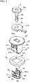
Fig. 1 is a disassembled perspective view of a clip for grounding according to one embodiment of the present invention. -
Fig. 2 is a disassembled perspective view of the clip for grounding viewed from a different direction. -
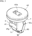
Fig. 3 is a perspective view wherein the clip for grounding is shown except for a pin member. -
Fig. 4 is a perspective view wherein the clip for grounding is shown except for the pin member, and is viewed from a different direction. -
Fig. 5 is a side view wherein the clip for grounding is shown except for the pin member, and is viewed from a different direction. -
Fig. 6 is a side view wherein the clip for grounding is shown except for the pin member, and is viewed from a different direction. -
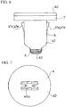
Fig. 7 is a plan view wherein the clip for grounding is shown except for the pin member. -
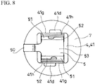
Fig. 8 is a bottom view wherein the clip for grounding is shown except for the pin member. -
Fig. 9 is a cross-sectional view taken along a position of line B-B inFig. 5 . -
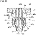
Fig. 10 is a cross-sectional view taken along a position of line A-A inFig. 5 . -
Fig. 11 is a side view of a grommet member forming the clip for grounding. -
Fig. 12 is a side view of the grommet member viewed from a different direction. -
Fig. 13 is a cross-sectional view taken along a position of line C-C inFig. 11 . -
Fig.14 is a cross-sectional view taken along a position of line D-D inFig. 12 . -
Fig. 15 is a cross-sectional view taken along a position of line E-E inFig. 12 . -
Fig. 16 is a cross-sectional view taken along a position of line F-F inFig. 12 . -
Fig. 17 is a plan view of a contact member forming the clip for grounding. -
Fig. 18 is a side view of the contact member. -
Fig. 19 is a side view of the contact member. -
Fig. 20 is a perspective view of essential parts showing a state wherein one portion of a grounding processing object is linked to an attachment object through the clip for grounding. -
Fig. 21 is a cross-sectional structural view showing a linked state inFig. 20 . -
Fig. 22 is a plan view of essential parts of the attachment object showing an attachment hole for the grommet member of the clip for grounding, formed in the attachment object. - Hereinafter, a typical embodiment of the present invention will be explained with reference to
Fig. 1 to Fig. 22 . A clip for grounding according to the present embodiment has a function of linking a grounding processing object 1 to a nonconductive attachment object 2 shown inFig. 21 to Fig. 22 , and also in association with this linking, a function of electrically connecting the grounding processing object 1 to a reference potential member 3 shown inFig. 21 to Fig. 22 . -
Fig. 21 shows an example wherein the grounding processing object 1 is a cap (not shown in the drawings) of a fuel filling aperture of an automobile, and a conductive tether 1a connected to the cap; the attachment object 2 is a fuel-filling-aperture forming member 2a wherein an inside thereof is aninsertion space 2b for a fueling gun; and the reference potential member 3 is a body panel 3a of the automobile. - Although the fuel-filling-aperture forming member 2a is formed of a nonconductive synthetic resin, the clip for grounding is connected to the cap through the tether 1a, and an
elastic contact portion 50 of the later-describedcontact member 5 contacts the body panel 3a positioned on an inner face side of the fuel-filling-aperture forming member 2a, so that the cap is connected to the fuel-filling-aperture forming member 2a in a state wherein grounding processing is carried out. - In an illustrated example, the later-described
pin member 6 inserted to pass through ahole 1b formed in one end portion of the tether 1a as one portion of the grounding processing object 1 fits into acenter portion 41a (seeFig. 10 ) of the later-describedgrommet member 4 so as to electrically connect the grounding processing object 1 and thegrommet member 4. Thereby, in the illustrated example, the cap connected to the other end portion of the tether 1a around thepin member 6 is connected to the fuel-filling-aperture forming member 2a in a turnable state. - In the present embodiment, the clip for grounding is formed by the
grommet member 4, thecontact member 5, thepin member 6, and apacking member 7. - The
grommet member 4 is made of a conductive resin. Thepin member 6 is typically formed of a material having a conductive property as well, and it is typically preferably made of the conductive resin. Thecontact member 5 is made of metal, and has the conductive property. - The
grommet member 4 is electrically connected to the grounding processing object 1, and fits into anattachment hole 2c formed in the nonconductive attachment object 2 so as to have a structure of linking the grounding processing object 1 to the attachment object 2. - In the illustrated example, as shown in
Fig. 1 andFig. 2 , thegrommet member 4 comprises a disk-shaped head portion 40, and afitting portion 41 into theattachment hole 2c. Thehead portion 40 has a size which does not enter into theattachment hole 2c. By thehead portion 40, thegrommet member 4 comprises aflange 42 forming an outer flange shape on abase portion 44 side thereof. Thehead portion 40 and thefitting portion 41 are integrated on one face side of thehead portion 40. - As shown in
Fig. 10 to Fig. 13 , thefitting portion 41 includes thecenter portion 41a, awall portion 41g, and aninsertion gap 41h formed between thecenter portion 41a and thewall portions 41g. - The
center portion 41a has a cylindrical shape in which atip 43 side of thegrommet member 4, i.e., a side which becomes an insertion side of thegrommet member 4 relative to theattachment hole 2c, is closed, and thebase portion 44 side which is opposite to thetip 43 side, is open. Thecenter portion 41a is integrated with thehead portion 40 on thebase portion 44 side. In the illustrated example, thecenter portion 41a has a rectangular cylindrical shape wherein an outline shape in cross section in a direction orthogonal to a fitting direction x (seeFig. 5 ) is a rectangle. In thehead portion 40, there is formed aninsertion hole 40a of the pin member 6 (seeFig. 1 ), and theinsertion hole 40a communicates with an inside of thecenter portion 41a. - Since the
center portion 41a opens only on thebase portion 44 side of thegrommet member 4, in a state wherein the tether 1a as one portion of the grounding processing object 1 is attached to the fuel-filling-aperture forming member 2a as the attachment object 2, rainwater and the like do not enter into a vehicle inside of the automobile through thecenter portion 41a of thegrommet member 4. - As shown in
Fig. 14 , at four corner portions in thecenter portion 41a, there are respectively formed rib-shapedportions 41c projecting in a direction orthogonal to a long-sideside face portions 41b of thecenter portion 41a. - As shown in
Fig. 13 , thewall portions 41g are respectively formed on an outside of two long-sideside face portions 41b of thecenter portion 41a. Thewall portion 41g has a band plate shape provided between the rib-shapedportions side face portion 41b. Thewall portion 41g is provided in a position between thetip 43 and thebase portion 44 of thegrommet member 4. - As shown in
Fig. 9 , there is formed anexit portion 41i of theinsertion gap 41h by an edge portion facing thebase portion 44 side of thegrommet member 4 in thewall portion 41g. Also, anentrance portion 41j of theinsertion gap 41h is formed by an edge portion facing thetip 43 side of thegrommet member 4 in thewall portion 41g. - Also, on the outside of the two long-side
side face portions center portion 41a, there are respectively formedengagement portions 41d engaging the attachment holes 2c on an insertion tip side, i.e., a fitting tip side Fw (seeFig. 21 ) when thegrommet member 4 is inserted into theattachment hole 2c. - In the illustrated example, the
engagement portion 41d is formed by an elastic piece projecting toward thehead portion 40 side from the edge portion facing thebase portion 44 side of thegrommet member 4 in thewall portion 41g. An inner face of the elastic piece is positioned on a face same as an inner face of thewall portion 41g. As shown inFig. 10 , an outer face of the elastic piece becomes aninclined face 41e gradually increasing a thickness of the elastic piece as separating from a connection side to thewall portion 41g. - Also, in the illustrated example, the
engagement portion 41d is formed on one side sandwiching a straight line y (seeFig. 5 ) substantially dividing the long-sideside face portion 41b of thecenter portion 41a into two to the right and left along the fitting direction x. Namely, theexit portion 41i of theinsertion gap 41h is formed on the other side sandwiching the straight line y. - In the illustrated example, relative to the
engagement portion 41d and theexit portion 41i formed on the outside of one of the two long-sideside face portions engagement portion 41d and theexit portion 41i formed on the outside of the other of the two long-sideside face portions Fig. 14 ) of thecenter portion 41a. - In the illustrated example, as shown in
Fig. 22 , theattachment hole 2c comprises a rectangularmain hole portion 2d following the outline shape in cross section of thecenter portion 41a of thefitting portion 41; and aconcave portion 2e formed at an intermediate position of one of two width-side hole edge portions of themain hole portion 2d. A distance between two length-sidehole edge portions main hole portion 2d is slightly smaller than a distance between the outer faces of the elastic pieces forming the twoengagement portions grommet member 4 on thebase portion 44 side. Also, a distance between thehead portion 40 of thegrommet member 4 and an end portion of the elastic piece forming theengagement portion 41d on thebase portion 44 side is substantially equal to a thickness of the fuel-filling-aperture forming member 2a at a portion forming theattachment hole 2c. Thereby, in the illustrated example, when thegrommet member 4 is inserted into theattachment hole 2c from a vehicle outside of the automobile, the aforementioned insertion is allowed while bending the elastic pieces forming the twoengagement portions 41d inwardly, and by a bending return of the elastic piece forming theengagement portion 41d at an insertion end position, the elastic piece forming theengagement portion 41d and thehead portion 40 sandwich the portion forming theattachment hole 2c therebetween from the inside and outside, thereby fitting thegrommet member 4 into theattachment hole 2c. - The
contact member 5 is combined with thegrommet member 4, and is formed by comprising theelastic contact portion 50 relative to the reference potential member 3 positioned on the fitting tip side Fw of the grommet member 4 (seeFig. 1 andFig. 2 ). - Also, the
contact member 5 includes a pair ofelastic engagement pieces insertion gaps 41h formed between thecenter portion 41a and thewall portions 41g from thetip 43 side of the grommet member 4 (seeFig. 9 ). Then, thecontact member 5 engagesengagement portions 51b of theelastic engagement pieces 51 with theexit portion 41i of theinsertion gaps 41h by an elastic return of theelastic engagement pieces 51 at an insertion end position into theinsertion gaps 41h (seeFig. 10 ). - Also, the
contact member 5 includes a pair ofelastic clamping pieces insertion gaps 41h from thetip 43 side of thegrommet member 4. Then, thecontact member 5 is combined with thegrommet member 4 in a state wherein thecenter portion 41a is clamped between the pair ofelastic clamping pieces - In the illustrated example, the
contact member 5 is formed by cutting and folding a metal plate. - As shown in
Fig. 17 , thecontact member 5 includes abase plate portion 53 having substantially a rectangular shape. - A base portion side of the
elastic contact portion 50 having a band plate shape is integrally connected to one of two width-side side portions base plate portion 53, and theelastic contact portion 50 has an arm shape projecting from thebase plate portion 53. Theelastic contact portion 50 projects in such a way so as to have an inclination which gradually increases a distance to the width-side side portion 53a of thebase plate portion 53 as coming close to a tip thereof. Also, as shown inFig. 18 , the tip of theelastic contact portion 50 is folded on a width-side side portion 53a side of thebase plate portion 53, and on an outside opposite to a side facing thebase plate portion 53 in theelastic contact portion 50, there is formed ashoulder portion 50a by the aforementioned folding. - Also, the
contact member 5 comprises two risingportions base plate portion 53 by bending two length-side side portions base plate portion 53 as a bending portion (seeFig. 18 ). In the two risingportions division grooves 55 leading to an approximately middle position in a rising direction from a tip thereof, and by thedivision grooves 55, theelastic engagement pieces 51 and theelastic clamping pieces 52 are formed respectively in the two risingportions - In the illustrated example, relative to the
elastic engagement piece 51 and theelastic clamping piece 52 formed on one side of the two length-side side portions 53b of thebase plate portion 53, theelastic engagement piece 51 and theelastic clamping piece 52 formed on one side of the two length-side side portions 53b of thebase plate portion 53 are disposed in a point-symmetry position around a center z' (seeFig. 17 ) of thebase plate portion 53. - In a state wherein the
contact member 5 is viewed from the width-side side portion 53a side of the base plate portion 53 (seeFig. 19 ), the pair ofelastic engagement pieces elastic engagement pieces engagement portions 51b formed on roughly an upper end side thereof. Upper sides relative to the bending portions which become theengagement portions 51b of theelastic engagement pieces 51 becomeinsertion guide portions 51a inclining toward a direction of gradually reducing the distance between the pair ofelastic engagement pieces - On the other hand, in the state wherein the
contact member 5 is viewed from the width-side side portion 53a side of the base plate portion 53 (seeFig. 19 ), the pair ofelastic clamping pieces elastic clamping pieces - When the
base plate portion 53 of thecontact member 5 faces thetip 43 of thegrommet member 4, and the respective correspondingelastic engagement piece 51 andelastic clamping piece 52 are inserted into the twoinsertion gaps 41h of thegrommet member 4 from theentrance portion 41j side, the pair ofelastic clamping pieces center portion 41a by respectively sliding to contact the long-sideside face portions 41b of thecenter portion 41a. Thereby, the pair ofelastic engagement pieces insertion guide portions 51a into theinsertion gaps 41h without being caught on theentrance portions 41j of theinsertion gaps 41h. When theelastic engagement piece 51 and theelastic clamping piece 52 are inserted into theinsertion gap 41h to a position where thebase plate portion 53 of thecontact member 5 abuts against thetip 43 of thegrommet member 4, theelastic engagement piece 51 bends outwardly, and the bending portion which becomes theengagement portion 51b is caught on theexit portion 41i of theinsertion gap 41h so as to prevent theelastic engagement piece 51 and theelastic clamping piece 52 from coming out of theinsertion gap 41h. Thereby, a combined state between thegrommet member 4 and thecontact member 5 is maintained. - The
grommet member 4 and thecontact member 5 are appropriately electrically connected by theelastic engagement piece 51 and theelastic clamping piece 52. - When the
grommet member 4 fits into theattachment hole 2c, theelastic contact portion 50 advances to the fitting tip side Fw of theattachment hole 2c through theconcave portion 2e. In the illustrated example, theelastic contact portion 50 advanced in the aforementioned manner contacts relative to an edge portion of the body panel 3a positioned on a vehicle inside of the fuel-filling-aperture forming member 2a in a state slightly elastically deformed in a direction of coming close to thebase plate portion 53. - By a contact to the body panel 3a as the reference potential member 3 of the
elastic contact portion 50, even in a case wherein theattachment hole 2c is provided in the fuel-filling-aperture forming member 2a as the attachment object 2, the tether 1a and the cap as the grounding processing object 1 can be appropriately electrically connected to the reference potential member 3 through the clip for grounding. Since theelastic contact portion 50 is formed by one portion of thecontact member 5 made of metal, an elastic deformation force is difficult to be lost over time, and theelastic contact portion 50 continues to contact the body panel 3a as the reference potential member 3 with a fixed elastic force. Also, since theelastic contact portion 50 can contact the body panel 3a as the reference potential member 3 with the fixed elastic force, even in a case wherein there is a slight error in a positional relationship between theattachment hole 2c and aportion 3b which becomes a contact point for grounding the body panel 3a as the reference potential member 3, the aforementioned error is absorbed so as to contact theelastic contact portion 50 with the body panel 3a as the reference potential member 3. - In the illustrated example, relative to the
grommet member 4 fitted into theattachment hole 2c, in a case wherein an external force large enough for pulling out thegrommet member 4 fitted into theattachment hole 2c acts, by a shape of theshoulder portion 50a of theelastic contact portion 50 of thecontact member 5, theelastic contact portion 50 passes theconcave portion 2e while elastically deforming in the direction of coming close to thebase plate portion 53, and comes out of the fuel-filling-aperture forming member 2a as the attachment object 2 together with thegrommet member 4 without separating from thegrommet member 4. - As shown in
Fig. 1 , thepin member 6 has a structure comprising a disk-shapedhead portion 6a and ashaft portion 6b projecting from a center of one face side of thehead portion 6a. There is formed aconstriction portion 6c between a tip and a base portion of theshaft portion 6b. As shown inFig. 13 , inside thecenter portion 41a of thegrommet member 4, there is formed aprotrusion portion 41f relative to theconstriction portion 6c. When theshaft portion 6b of thepin member 6 is inserted into thecenter portion 41a, the tip of thepin member 6 abuts against theprotrusion portion 41f, and thecenter portion 41a elastically deforms to allow an insertion of thepin member 6 further inside. When thepin member 6 is inserted into thecenter portion 41a to a position of interposing one end portion of the tether 1a as one portion of the grounding processing object 1 between thehead portion 6a of thepin member 6 and thehead portion 40 of thegrommet member 4, acenter portion 41a side elastically returns, and theprotrusion portion 41f engages theconstriction portion 6c. - As shown in
Fig. 1 andFig. 2 , the packingmember 7 has a structure of sealing fluid-tightly between theflange 42 formed by thehead portion 40 of thegrommet member 4 and theattachment hole 2c. The packingmember 7 includes a throughhole 7a for thegrommet member 4, which follows the outline shape in cross section of thecenter portion 41a, and is provided in thegrommet member 4 in such a way so as to contact one surface thereof with theflange 42 by passing thefitting portion 41 of thegrommet member 4 through the throughhole 7a. - In a state wherein the tether 1a as one portion of the grounding processing object 1 is attached to the fuel-filling-aperture forming member 2a as the attachment object 2 as mentioned above, the rainwater and the like do not enter into the vehicle inside of the automobile through the
center portion 41a of thegrommet member 4. Therewith, the rainwater and the like do not enter into the vehicle inside of the automobile between thegrommet member 4 and theattachment hole 2c as well by the packingmember 7. - Incidentally, obviously, the present invention is not limited to the embodiment explained hereinabove, and includes all embodiments which can obtain the object of the present invention.
-
- 1
- a grounding processing object
- 2
- an attachment object
- 2c
- an attachment hole
- 3
- a reference potential member
- 4
- a grommet member
- 5
- a contact member
- 50
- an elastic contact portion
- Fw
- a fitting tip side
- Incidentally, the specification, claims, drawings, and abstract of Japanese Patent Application No.
2016-108855 filed on May 31, 2016
Claims (6)
- A clip for grounding, comprising:a grommet member made of a conductive resin, electrically connected to a grounding processing object, and fitted into an attachment hole formed in a nonconductive attachment object so as to link the grounding processing object to the attachment object; anda contact member made of metal, assembled with the grommet member, and including an elastic contact portion relative to a reference potential member positioned on a fitting tip side of the grommet member.
- A clip for grounding according to claim 1, wherein the grommet member includes wall portions respectively on two sides sandwiching a center portion thereof,the contact member includes a pair of elastic engagement pieces to be inserted into an insertion gap formed between the center portion and the wall portions from a tip side of the grommet member, andby an elastic return of the elastic engagement piece at an insertion end position into the insertion gap, an engagement portion of the elastic engagement piece engages an exit portion of the insertion gap.
- A clip for grounding according to claim 2, wherein the contact member includes a pair of elastic clamping pieces to be inserted into the insertion gap from the tip side of the grommet member, and
in a state wherein the center portion is clamped between the pair of elastic clamping pieces, the contact member is combined with the grommet member. - A clip for grounding according to any one of claims 1 to 3, wherein the center portion of the grommet member has a cylindrical shape in which a tip side of the grommet member is closed, and a base portion side is open, and includes a pin member to be fitted into the center portion from the base portion side, and
the pin member inserted to pass through a hole formed in one portion of the grounding processing object fits into the center portion to thereby electrically connect the grounding processing object and the grommet member. - A clip for grounding according to claim 4, wherein the grommet member includes a flange on a base portion side, and
a packing member for sealing fluid-tightly between the flange and the attachment hole is provided. - A clip for grounding according to any one of claims 1 to 5, wherein the grounding processing object is a cap of a fuel filling aperture of an automobile and a conductive tether connected to the cap,the attachment object is a fuel-filling-aperture forming member wherein an inside thereof is an insertion space for a fueling gun, andthe reference potential member is a body panel of the automobile.
Applications Claiming Priority (2)
| Application Number | Priority Date | Filing Date | Title |
|---|---|---|---|
| JP2016108855A JP6498151B2 (en) | 2016-05-31 | 2016-05-31 | Grounding clip |
| PCT/JP2017/016575 WO2017208691A1 (en) | 2016-05-31 | 2017-04-26 | Clip for grounding |
Publications (3)
| Publication Number | Publication Date |
|---|---|
| EP3467943A1 true EP3467943A1 (en) | 2019-04-10 |
| EP3467943A4 EP3467943A4 (en) | 2020-01-15 |
| EP3467943B1 EP3467943B1 (en) | 2021-08-04 |
Family
ID=60479349
Family Applications (1)
| Application Number | Title | Priority Date | Filing Date |
|---|---|---|---|
| EP17806250.1A Active EP3467943B1 (en) | 2016-05-31 | 2017-04-26 | An assembly comprising a clip for grounding, a grounding processing object, a nonconductive attachment object and a reference potential member |
Country Status (7)
| Country | Link |
|---|---|
| US (1) | US10446947B2 (en) |
| EP (1) | EP3467943B1 (en) |
| JP (1) | JP6498151B2 (en) |
| KR (1) | KR101917030B1 (en) |
| CN (1) | CN109075465B (en) |
| MX (1) | MX388772B (en) |
| WO (1) | WO2017208691A1 (en) |
Families Citing this family (6)
| Publication number | Priority date | Publication date | Assignee | Title |
|---|---|---|---|---|
| JP1645875S (en) * | 2019-05-27 | 2019-11-18 | ||
| USD947128S1 (en) * | 2019-06-27 | 2022-03-29 | Luen Yick Electrical Manufacturing Co. Ltd. | Electrical socket |
| KR20210017789A (en) | 2019-08-09 | 2021-02-17 | 삼성전자주식회사 | Display apparatus |
| JP7720273B2 (en) * | 2022-03-07 | 2025-08-07 | 株式会社ニフコ | Sensor Bracket |
| USD1008972S1 (en) | 2023-05-17 | 2023-12-26 | Liqing LIAO | Insert socket |
| USD1081583S1 (en) * | 2024-09-02 | 2025-07-01 | Ningbo Eudemon Child Protective Equipment Co., Ltd. | Safety cover for electric socket |
Family Cites Families (8)
| Publication number | Priority date | Publication date | Assignee | Title |
|---|---|---|---|---|
| JP2001260666A (en) * | 2000-03-22 | 2001-09-26 | Piolax Inc | Anti-static device for conductive resin tube |
| US7168138B2 (en) * | 2000-03-27 | 2007-01-30 | Newfrey Llc | Resilient clip fastener |
| US7134170B2 (en) * | 2001-11-21 | 2006-11-14 | Newfrey Llc | Plastic retaining clip for rib attachment |
| EP1387440B1 (en) * | 2002-07-30 | 2012-02-22 | TI Automotive (Fuldabrück) GmbH | Method for grounding a coated metallic pipe and a clip used for this method |
| JP4528513B2 (en) * | 2003-10-21 | 2010-08-18 | 日産自動車株式会社 | Parts mounting structure to fuel tank |
| JP2009061974A (en) | 2007-09-07 | 2009-03-26 | Honda Motor Co Ltd | Fuel lid structure |
| JP2013222527A (en) | 2012-04-13 | 2013-10-28 | Auto Network Gijutsu Kenkyusho:Kk | Electric wire with ground terminal, and ground terminal |
| JP2016108855A (en) | 2014-12-08 | 2016-06-20 | 大和薬品株式会社 | Emergency shutdown device |
-
2016
- 2016-05-31 JP JP2016108855A patent/JP6498151B2/en active Active
-
2017
- 2017-04-26 US US16/091,827 patent/US10446947B2/en active Active
- 2017-04-26 CN CN201780026698.6A patent/CN109075465B/en active Active
- 2017-04-26 EP EP17806250.1A patent/EP3467943B1/en active Active
- 2017-04-26 MX MX2018012315A patent/MX388772B/en unknown
- 2017-04-26 WO PCT/JP2017/016575 patent/WO2017208691A1/en not_active Ceased
- 2017-05-30 KR KR1020170067062A patent/KR101917030B1/en active Active
Also Published As
| Publication number | Publication date |
|---|---|
| KR20170135755A (en) | 2017-12-08 |
| JP6498151B2 (en) | 2019-04-10 |
| JP2017216120A (en) | 2017-12-07 |
| MX388772B (en) | 2025-03-20 |
| CN109075465B (en) | 2021-03-02 |
| EP3467943B1 (en) | 2021-08-04 |
| MX2018012315A (en) | 2019-02-20 |
| US20190089073A1 (en) | 2019-03-21 |
| US10446947B2 (en) | 2019-10-15 |
| CN109075465A (en) | 2018-12-21 |
| KR101917030B1 (en) | 2018-11-08 |
| EP3467943A4 (en) | 2020-01-15 |
| WO2017208691A1 (en) | 2017-12-07 |
Similar Documents
| Publication | Publication Date | Title |
|---|---|---|
| EP3467943B1 (en) | An assembly comprising a clip for grounding, a grounding processing object, a nonconductive attachment object and a reference potential member | |
| US9412989B2 (en) | Battery connecting assembly | |
| KR101798349B1 (en) | Holding frame for a plug-type connector | |
| US10326228B2 (en) | Connector having terminal with insulated tip and edges | |
| US11158962B2 (en) | Terminal cover | |
| KR900003089Y1 (en) | Insulating cover for terminal | |
| US9640916B2 (en) | Shield connector | |
| US10670636B2 (en) | Current detection device | |
| JP2012164520A (en) | Relay connector | |
| US11050227B2 (en) | Electric connection box | |
| JP7189822B2 (en) | connector structure | |
| US10910757B2 (en) | Connector having slidable locking cover | |
| US20180183166A1 (en) | Connector | |
| US10249977B2 (en) | Connector, connector cover, and wire harness | |
| US20250105554A1 (en) | Connector | |
| US10770878B1 (en) | Electric connection box | |
| CN113453957B (en) | Cable guide and wire harness device | |
| US10096925B2 (en) | Connector | |
| US12500367B2 (en) | Terminal unit with improved protection | |
| JP7086496B2 (en) | Packing mounting structure | |
| KR102957750B1 (en) | Connector and connector assembly comprisng the same | |
| EP3993175A1 (en) | Sealed connector housing for an angled electrical connector | |
| US20250105555A1 (en) | Connector | |
| JP7512992B2 (en) | connector | |
| US12119586B2 (en) | Connector |
Legal Events
| Date | Code | Title | Description |
|---|---|---|---|
| STAA | Information on the status of an ep patent application or granted ep patent |
Free format text: STATUS: THE INTERNATIONAL PUBLICATION HAS BEEN MADE |
|
| PUAI | Public reference made under article 153(3) epc to a published international application that has entered the european phase |
Free format text: ORIGINAL CODE: 0009012 |
|
| STAA | Information on the status of an ep patent application or granted ep patent |
Free format text: STATUS: REQUEST FOR EXAMINATION WAS MADE |
|
| 17P | Request for examination filed |
Effective date: 20181025 |
|
| AK | Designated contracting states |
Kind code of ref document: A1 Designated state(s): AL AT BE BG CH CY CZ DE DK EE ES FI FR GB GR HR HU IE IS IT LI LT LU LV MC MK MT NL NO PL PT RO RS SE SI SK SM TR |
|
| AX | Request for extension of the european patent |
Extension state: BA ME |
|
| DAV | Request for validation of the european patent (deleted) | ||
| DAX | Request for extension of the european patent (deleted) | ||
| A4 | Supplementary search report drawn up and despatched |
Effective date: 20191216 |
|
| RIC1 | Information provided on ipc code assigned before grant |
Ipc: H01R 4/64 20060101AFI20191210BHEP Ipc: H01R 13/74 20060101ALI20191210BHEP Ipc: H01R 4/66 20060101ALI20191210BHEP Ipc: H01R 11/12 20060101ALI20191210BHEP Ipc: B60K 15/05 20060101ALI20191210BHEP |
|
| GRAP | Despatch of communication of intention to grant a patent |
Free format text: ORIGINAL CODE: EPIDOSNIGR1 |
|
| STAA | Information on the status of an ep patent application or granted ep patent |
Free format text: STATUS: GRANT OF PATENT IS INTENDED |
|
| INTG | Intention to grant announced |
Effective date: 20210316 |
|
| GRAS | Grant fee paid |
Free format text: ORIGINAL CODE: EPIDOSNIGR3 |
|
| GRAA | (expected) grant |
Free format text: ORIGINAL CODE: 0009210 |
|
| STAA | Information on the status of an ep patent application or granted ep patent |
Free format text: STATUS: THE PATENT HAS BEEN GRANTED |
|
| AK | Designated contracting states |
Kind code of ref document: B1 Designated state(s): AL AT BE BG CH CY CZ DE DK EE ES FI FR GB GR HR HU IE IS IT LI LT LU LV MC MK MT NL NO PL PT RO RS SE SI SK SM TR |
|
| RAP3 | Party data changed (applicant data changed or rights of an application transferred) |
Owner name: NIFCO INC. |
|
| REG | Reference to a national code |
Ref country code: GB Ref legal event code: FG4D |
|
| REG | Reference to a national code |
Ref country code: AT Ref legal event code: REF Ref document number: 1417955 Country of ref document: AT Kind code of ref document: T Effective date: 20210815 |
|
| REG | Reference to a national code |
Ref country code: CH Ref legal event code: EP |
|
| REG | Reference to a national code |
Ref country code: DE Ref legal event code: R096 Ref document number: 602017043478 Country of ref document: DE |
|
| REG | Reference to a national code |
Ref country code: IE Ref legal event code: FG4D |
|
| REG | Reference to a national code |
Ref country code: LT Ref legal event code: MG9D |
|
| REG | Reference to a national code |
Ref country code: NL Ref legal event code: MP Effective date: 20210804 |
|
| REG | Reference to a national code |
Ref country code: AT Ref legal event code: MK05 Ref document number: 1417955 Country of ref document: AT Kind code of ref document: T Effective date: 20210804 |
|
| PG25 | Lapsed in a contracting state [announced via postgrant information from national office to epo] |
Ref country code: RS Free format text: LAPSE BECAUSE OF FAILURE TO SUBMIT A TRANSLATION OF THE DESCRIPTION OR TO PAY THE FEE WITHIN THE PRESCRIBED TIME-LIMIT Effective date: 20210804 Ref country code: SE Free format text: LAPSE BECAUSE OF FAILURE TO SUBMIT A TRANSLATION OF THE DESCRIPTION OR TO PAY THE FEE WITHIN THE PRESCRIBED TIME-LIMIT Effective date: 20210804 Ref country code: FI Free format text: LAPSE BECAUSE OF FAILURE TO SUBMIT A TRANSLATION OF THE DESCRIPTION OR TO PAY THE FEE WITHIN THE PRESCRIBED TIME-LIMIT Effective date: 20210804 Ref country code: ES Free format text: LAPSE BECAUSE OF FAILURE TO SUBMIT A TRANSLATION OF THE DESCRIPTION OR TO PAY THE FEE WITHIN THE PRESCRIBED TIME-LIMIT Effective date: 20210804 Ref country code: HR Free format text: LAPSE BECAUSE OF FAILURE TO SUBMIT A TRANSLATION OF THE DESCRIPTION OR TO PAY THE FEE WITHIN THE PRESCRIBED TIME-LIMIT Effective date: 20210804 Ref country code: NO Free format text: LAPSE BECAUSE OF FAILURE TO SUBMIT A TRANSLATION OF THE DESCRIPTION OR TO PAY THE FEE WITHIN THE PRESCRIBED TIME-LIMIT Effective date: 20211104 Ref country code: PT Free format text: LAPSE BECAUSE OF FAILURE TO SUBMIT A TRANSLATION OF THE DESCRIPTION OR TO PAY THE FEE WITHIN THE PRESCRIBED TIME-LIMIT Effective date: 20211206 Ref country code: AT Free format text: LAPSE BECAUSE OF FAILURE TO SUBMIT A TRANSLATION OF THE DESCRIPTION OR TO PAY THE FEE WITHIN THE PRESCRIBED TIME-LIMIT Effective date: 20210804 Ref country code: BG Free format text: LAPSE BECAUSE OF FAILURE TO SUBMIT A TRANSLATION OF THE DESCRIPTION OR TO PAY THE FEE WITHIN THE PRESCRIBED TIME-LIMIT Effective date: 20211104 Ref country code: LT Free format text: LAPSE BECAUSE OF FAILURE TO SUBMIT A TRANSLATION OF THE DESCRIPTION OR TO PAY THE FEE WITHIN THE PRESCRIBED TIME-LIMIT Effective date: 20210804 |
|
| PG25 | Lapsed in a contracting state [announced via postgrant information from national office to epo] |
Ref country code: PL Free format text: LAPSE BECAUSE OF FAILURE TO SUBMIT A TRANSLATION OF THE DESCRIPTION OR TO PAY THE FEE WITHIN THE PRESCRIBED TIME-LIMIT Effective date: 20210804 Ref country code: LV Free format text: LAPSE BECAUSE OF FAILURE TO SUBMIT A TRANSLATION OF THE DESCRIPTION OR TO PAY THE FEE WITHIN THE PRESCRIBED TIME-LIMIT Effective date: 20210804 Ref country code: GR Free format text: LAPSE BECAUSE OF FAILURE TO SUBMIT A TRANSLATION OF THE DESCRIPTION OR TO PAY THE FEE WITHIN THE PRESCRIBED TIME-LIMIT Effective date: 20211105 |
|
| PG25 | Lapsed in a contracting state [announced via postgrant information from national office to epo] |
Ref country code: NL Free format text: LAPSE BECAUSE OF FAILURE TO SUBMIT A TRANSLATION OF THE DESCRIPTION OR TO PAY THE FEE WITHIN THE PRESCRIBED TIME-LIMIT Effective date: 20210804 |
|
| PG25 | Lapsed in a contracting state [announced via postgrant information from national office to epo] |
Ref country code: DK Free format text: LAPSE BECAUSE OF FAILURE TO SUBMIT A TRANSLATION OF THE DESCRIPTION OR TO PAY THE FEE WITHIN THE PRESCRIBED TIME-LIMIT Effective date: 20210804 |
|
| PGFP | Annual fee paid to national office [announced via postgrant information from national office to epo] |
Ref country code: GB Payment date: 20220303 Year of fee payment: 6 |
|
| REG | Reference to a national code |
Ref country code: DE Ref legal event code: R097 Ref document number: 602017043478 Country of ref document: DE |
|
| PG25 | Lapsed in a contracting state [announced via postgrant information from national office to epo] |
Ref country code: SM Free format text: LAPSE BECAUSE OF FAILURE TO SUBMIT A TRANSLATION OF THE DESCRIPTION OR TO PAY THE FEE WITHIN THE PRESCRIBED TIME-LIMIT Effective date: 20210804 Ref country code: SK Free format text: LAPSE BECAUSE OF FAILURE TO SUBMIT A TRANSLATION OF THE DESCRIPTION OR TO PAY THE FEE WITHIN THE PRESCRIBED TIME-LIMIT Effective date: 20210804 Ref country code: RO Free format text: LAPSE BECAUSE OF FAILURE TO SUBMIT A TRANSLATION OF THE DESCRIPTION OR TO PAY THE FEE WITHIN THE PRESCRIBED TIME-LIMIT Effective date: 20210804 Ref country code: EE Free format text: LAPSE BECAUSE OF FAILURE TO SUBMIT A TRANSLATION OF THE DESCRIPTION OR TO PAY THE FEE WITHIN THE PRESCRIBED TIME-LIMIT Effective date: 20210804 Ref country code: CZ Free format text: LAPSE BECAUSE OF FAILURE TO SUBMIT A TRANSLATION OF THE DESCRIPTION OR TO PAY THE FEE WITHIN THE PRESCRIBED TIME-LIMIT Effective date: 20210804 Ref country code: AL Free format text: LAPSE BECAUSE OF FAILURE TO SUBMIT A TRANSLATION OF THE DESCRIPTION OR TO PAY THE FEE WITHIN THE PRESCRIBED TIME-LIMIT Effective date: 20210804 |
|
| PLBE | No opposition filed within time limit |
Free format text: ORIGINAL CODE: 0009261 |
|
| STAA | Information on the status of an ep patent application or granted ep patent |
Free format text: STATUS: NO OPPOSITION FILED WITHIN TIME LIMIT |
|
| 26N | No opposition filed |
Effective date: 20220506 |
|
| PG25 | Lapsed in a contracting state [announced via postgrant information from national office to epo] |
Ref country code: IT Free format text: LAPSE BECAUSE OF FAILURE TO SUBMIT A TRANSLATION OF THE DESCRIPTION OR TO PAY THE FEE WITHIN THE PRESCRIBED TIME-LIMIT Effective date: 20210804 |
|
| PG25 | Lapsed in a contracting state [announced via postgrant information from national office to epo] |
Ref country code: SI Free format text: LAPSE BECAUSE OF FAILURE TO SUBMIT A TRANSLATION OF THE DESCRIPTION OR TO PAY THE FEE WITHIN THE PRESCRIBED TIME-LIMIT Effective date: 20210804 |
|
| REG | Reference to a national code |
Ref country code: CH Ref legal event code: PL |
|
| REG | Reference to a national code |
Ref country code: BE Ref legal event code: MM Effective date: 20220430 |
|
| PG25 | Lapsed in a contracting state [announced via postgrant information from national office to epo] |
Ref country code: MC Free format text: LAPSE BECAUSE OF FAILURE TO SUBMIT A TRANSLATION OF THE DESCRIPTION OR TO PAY THE FEE WITHIN THE PRESCRIBED TIME-LIMIT Effective date: 20210804 Ref country code: LU Free format text: LAPSE BECAUSE OF NON-PAYMENT OF DUE FEES Effective date: 20220426 Ref country code: LI Free format text: LAPSE BECAUSE OF NON-PAYMENT OF DUE FEES Effective date: 20220430 Ref country code: CH Free format text: LAPSE BECAUSE OF NON-PAYMENT OF DUE FEES Effective date: 20220430 |
|
| PG25 | Lapsed in a contracting state [announced via postgrant information from national office to epo] |
Ref country code: BE Free format text: LAPSE BECAUSE OF NON-PAYMENT OF DUE FEES Effective date: 20220430 |
|
| PG25 | Lapsed in a contracting state [announced via postgrant information from national office to epo] |
Ref country code: IE Free format text: LAPSE BECAUSE OF NON-PAYMENT OF DUE FEES Effective date: 20220426 |
|
| GBPC | Gb: european patent ceased through non-payment of renewal fee |
Effective date: 20230426 |
|
| PG25 | Lapsed in a contracting state [announced via postgrant information from national office to epo] |
Ref country code: GB Free format text: LAPSE BECAUSE OF NON-PAYMENT OF DUE FEES Effective date: 20230426 |
|
| PG25 | Lapsed in a contracting state [announced via postgrant information from national office to epo] |
Ref country code: GB Free format text: LAPSE BECAUSE OF NON-PAYMENT OF DUE FEES Effective date: 20230426 |
|
| PG25 | Lapsed in a contracting state [announced via postgrant information from national office to epo] |
Ref country code: HU Free format text: LAPSE BECAUSE OF FAILURE TO SUBMIT A TRANSLATION OF THE DESCRIPTION OR TO PAY THE FEE WITHIN THE PRESCRIBED TIME-LIMIT; INVALID AB INITIO Effective date: 20170426 |
|
| PG25 | Lapsed in a contracting state [announced via postgrant information from national office to epo] |
Ref country code: MK Free format text: LAPSE BECAUSE OF FAILURE TO SUBMIT A TRANSLATION OF THE DESCRIPTION OR TO PAY THE FEE WITHIN THE PRESCRIBED TIME-LIMIT Effective date: 20210804 Ref country code: CY Free format text: LAPSE BECAUSE OF FAILURE TO SUBMIT A TRANSLATION OF THE DESCRIPTION OR TO PAY THE FEE WITHIN THE PRESCRIBED TIME-LIMIT Effective date: 20210804 |
|
| PG25 | Lapsed in a contracting state [announced via postgrant information from national office to epo] |
Ref country code: TR Free format text: LAPSE BECAUSE OF FAILURE TO SUBMIT A TRANSLATION OF THE DESCRIPTION OR TO PAY THE FEE WITHIN THE PRESCRIBED TIME-LIMIT Effective date: 20210804 |
|
| PG25 | Lapsed in a contracting state [announced via postgrant information from national office to epo] |
Ref country code: MT Free format text: LAPSE BECAUSE OF FAILURE TO SUBMIT A TRANSLATION OF THE DESCRIPTION OR TO PAY THE FEE WITHIN THE PRESCRIBED TIME-LIMIT Effective date: 20210804 |
|
| PGFP | Annual fee paid to national office [announced via postgrant information from national office to epo] |
Ref country code: DE Payment date: 20250305 Year of fee payment: 9 |
|
| PGFP | Annual fee paid to national office [announced via postgrant information from national office to epo] |
Ref country code: FR Payment date: 20260309 Year of fee payment: 10 |