EP3467924B1 - Redox flow battery piping, method for manufacturing redox flow battery piping, piping unit, and redox flow battery - Google Patents
Redox flow battery piping, method for manufacturing redox flow battery piping, piping unit, and redox flow battery Download PDFInfo
- Publication number
- EP3467924B1 EP3467924B1 EP17802498.0A EP17802498A EP3467924B1 EP 3467924 B1 EP3467924 B1 EP 3467924B1 EP 17802498 A EP17802498 A EP 17802498A EP 3467924 B1 EP3467924 B1 EP 3467924B1
- Authority
- EP
- European Patent Office
- Prior art keywords
- pipe
- redox flow
- flow battery
- battery
- branch pipes
- Prior art date
- Legal status (The legal status is an assumption and is not a legal conclusion. Google has not performed a legal analysis and makes no representation as to the accuracy of the status listed.)
- Not-in-force
Links
Images





Classifications
-
- H—ELECTRICITY
- H01—ELECTRIC ELEMENTS
- H01M—PROCESSES OR MEANS, e.g. BATTERIES, FOR THE DIRECT CONVERSION OF CHEMICAL ENERGY INTO ELECTRICAL ENERGY
- H01M8/00—Fuel cells; Manufacture thereof
- H01M8/04—Auxiliary arrangements, e.g. for control of pressure or for circulation of fluids
- H01M8/04082—Arrangements for control of reactant parameters, e.g. pressure or concentration
- H01M8/04201—Reactant storage and supply, e.g. means for feeding, pipes
-
- H—ELECTRICITY
- H01—ELECTRIC ELEMENTS
- H01M—PROCESSES OR MEANS, e.g. BATTERIES, FOR THE DIRECT CONVERSION OF CHEMICAL ENERGY INTO ELECTRICAL ENERGY
- H01M8/00—Fuel cells; Manufacture thereof
- H01M8/18—Regenerative fuel cells, e.g. redox flow batteries or secondary fuel cells
- H01M8/184—Regeneration by electrochemical means
- H01M8/188—Regeneration by electrochemical means by recharging of redox couples containing fluids; Redox flow type batteries
-
- B—PERFORMING OPERATIONS; TRANSPORTING
- B29—WORKING OF PLASTICS; WORKING OF SUBSTANCES IN A PLASTIC STATE IN GENERAL
- B29C—SHAPING OR JOINING OF PLASTICS; SHAPING OF MATERIAL IN A PLASTIC STATE, NOT OTHERWISE PROVIDED FOR; AFTER-TREATMENT OF THE SHAPED PRODUCTS, e.g. REPAIRING
- B29C39/00—Shaping by casting, i.e. introducing the moulding material into a mould or between confining surfaces without significant moulding pressure; Apparatus therefor
- B29C39/02—Shaping by casting, i.e. introducing the moulding material into a mould or between confining surfaces without significant moulding pressure; Apparatus therefor for making articles of definite length, i.e. discrete articles
- B29C39/04—Shaping by casting, i.e. introducing the moulding material into a mould or between confining surfaces without significant moulding pressure; Apparatus therefor for making articles of definite length, i.e. discrete articles using movable moulds not applied
- B29C39/08—Introducing the material into the mould by centrifugal force
-
- H—ELECTRICITY
- H01—ELECTRIC ELEMENTS
- H01M—PROCESSES OR MEANS, e.g. BATTERIES, FOR THE DIRECT CONVERSION OF CHEMICAL ENERGY INTO ELECTRICAL ENERGY
- H01M8/00—Fuel cells; Manufacture thereof
- H01M8/04—Auxiliary arrangements, e.g. for control of pressure or for circulation of fluids
-
- H—ELECTRICITY
- H01—ELECTRIC ELEMENTS
- H01M—PROCESSES OR MEANS, e.g. BATTERIES, FOR THE DIRECT CONVERSION OF CHEMICAL ENERGY INTO ELECTRICAL ENERGY
- H01M8/00—Fuel cells; Manufacture thereof
- H01M8/04—Auxiliary arrangements, e.g. for control of pressure or for circulation of fluids
- H01M8/04082—Arrangements for control of reactant parameters, e.g. pressure or concentration
- H01M8/04201—Reactant storage and supply, e.g. means for feeding, pipes
- H01M8/04216—Reactant storage and supply, e.g. means for feeding, pipes characterised by the choice for a specific material, e.g. carbon, hydride, absorbent
-
- H—ELECTRICITY
- H01—ELECTRIC ELEMENTS
- H01M—PROCESSES OR MEANS, e.g. BATTERIES, FOR THE DIRECT CONVERSION OF CHEMICAL ENERGY INTO ELECTRICAL ENERGY
- H01M8/00—Fuel cells; Manufacture thereof
- H01M8/04—Auxiliary arrangements, e.g. for control of pressure or for circulation of fluids
- H01M8/04276—Arrangements for managing the electrolyte stream, e.g. heat exchange
-
- H—ELECTRICITY
- H01—ELECTRIC ELEMENTS
- H01M—PROCESSES OR MEANS, e.g. BATTERIES, FOR THE DIRECT CONVERSION OF CHEMICAL ENERGY INTO ELECTRICAL ENERGY
- H01M8/00—Fuel cells; Manufacture thereof
- H01M8/18—Regenerative fuel cells, e.g. redox flow batteries or secondary fuel cells
-
- Y—GENERAL TAGGING OF NEW TECHNOLOGICAL DEVELOPMENTS; GENERAL TAGGING OF CROSS-SECTIONAL TECHNOLOGIES SPANNING OVER SEVERAL SECTIONS OF THE IPC; TECHNICAL SUBJECTS COVERED BY FORMER USPC CROSS-REFERENCE ART COLLECTIONS [XRACs] AND DIGESTS
- Y02—TECHNOLOGIES OR APPLICATIONS FOR MITIGATION OR ADAPTATION AGAINST CLIMATE CHANGE
- Y02E—REDUCTION OF GREENHOUSE GAS [GHG] EMISSIONS, RELATED TO ENERGY GENERATION, TRANSMISSION OR DISTRIBUTION
- Y02E60/00—Enabling technologies; Technologies with a potential or indirect contribution to GHG emissions mitigation
- Y02E60/30—Hydrogen technology
- Y02E60/50—Fuel cells
-
- Y—GENERAL TAGGING OF NEW TECHNOLOGICAL DEVELOPMENTS; GENERAL TAGGING OF CROSS-SECTIONAL TECHNOLOGIES SPANNING OVER SEVERAL SECTIONS OF THE IPC; TECHNICAL SUBJECTS COVERED BY FORMER USPC CROSS-REFERENCE ART COLLECTIONS [XRACs] AND DIGESTS
- Y02—TECHNOLOGIES OR APPLICATIONS FOR MITIGATION OR ADAPTATION AGAINST CLIMATE CHANGE
- Y02P—CLIMATE CHANGE MITIGATION TECHNOLOGIES IN THE PRODUCTION OR PROCESSING OF GOODS
- Y02P70/00—Climate change mitigation technologies in the production process for final industrial or consumer products
- Y02P70/50—Manufacturing or production processes characterised by the final manufactured product
Definitions
- the present invention relates to a redox flow battery pipe, a method for manufacturing a redox flow battery pipe, a pipe unit, and a redox flow battery.
- RF battery redox flow battery
- the RF battery supplies a positive electrolyte and a negative electrolyte to a battery element including a cell, which includes a positive electrode, a negative electrode, and a membrane disposed between the electrodes, so as to perform charging and discharging.
- Aqueous solutions containing metal ions, such as vanadium (V) ions, whose valence is changed by oxidation-reduction are used as the electrolytes.
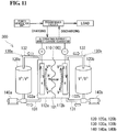
- Figure 11 is an operating principle diagram of a vanadium-based RF battery 300 in which vanadium electrolytes containing V ions are used as a positive electrolyte and a negative electrolyte.
- the solid-line arrows indicate a charging reaction
- the dashed-line arrows indicate a discharging reaction.
- the RF battery 300 includes a battery element 100.
- the battery element 100 includes a cell 110 including a positive electrode cell 112a that contains a positive electrode 102a therein, a negative electrode cell 112b that contains a negative electrode 102b therein, and a membrane 101 disposed between the electrode cells.
- the RF battery 300 includes tanks 120 (a positive electrolyte tank 120a and a negative electrolyte tank 120b) that store a positive electrolyte and a negative electrolyte, respectively, and electrolyte flow paths 130 (a positive electrolyte flow path 130a and a negative electrolyte flow path 130b) through which the electrolytes are circulated between the tanks 120 and the battery element 100 (cell 110).
- the electrolyte flow paths 130 include pipes 131 and 132 which are provided between the tanks 120 and the battery element 100 and through which the electrolytes flow.
- the tanks 120 and the battery element 100 are connected together with the pipes 131 and 132 therebetween.
- the pipes 131 are supply pipes through which the electrolytes are supplied from the tanks 120 to the cell 110 (the positive electrode cell 112a and the negative electrode cell 112b), and the pipes 132 are return pipes through which the electrolytes are returned from the cell 110 to the tanks 120.
- the electrolyte flow paths 130 (the pipes 131 in this example) are provided with pumps 140 (a positive electrolyte pump 140a and a negative electrolyte pump 140b) for pumping their corresponding electrolytes, respectively.
- the battery element 100 is used in the form of a cell stack in which a plurality of cells 110 each including the positive electrode 102a (positive electrode cell 112a), a negative electrode 102b (negative electrode cell 112b), and a membrane 101 disposed between the electrodes are stacked.
- Figure 12 is a schematic structural view of a cell stack.
- Cell frames 210 each including a bipolar plate 211 and a frame body 212 provided on the outer periphery of the bipolar plate 211 so as to be integrated with each other are used in a cell stack 200.
- the cell stack 200 is constituted by stacking a plurality of cells 110 with the cell frames 210 therebetween, the cells 110 each including a positive electrode 102a, a membrane 101, and a negative electrode 102b that overlap, sandwiching the resulting layered body from both sides thereof using two end plates 220, and fastening the layered body.
- a negative electrode (negative electrode cell) and a positive electrode (positive electrode cell) of adjacent cells 110 are disposed so as to sandwich a cell frame 210 (bipolar plate 211).
- Supply/drainage plates (not shown) each provided with a supply port through which an electrolyte is supplied and a drainage port through which the electrolyte is drained are disposed on the cell stack 200.
- the pipes 131 and 132 that form the electrolyte flow paths 130 (refer to Fig. 11 ) of the electrolytes are connected to the supply port and the drainage port, respectively.
- a redox flow battery pipe is a redox flow battery pipe which is disposed between a tank that stores an electrolyte and a battery element and through which the electrolyte flows, the pipe including a plurality of parallel portions arranged in parallel and a plurality of bent portions connecting the parallel portions adjacent to each other, wherein the pipe includes a meandering portion in which the parallel portions and the bent portions are integrally molded so as to be alternately connected, and a ratio of a center-to-center distance X to an outer diameter D satisfies 1.2 or more and 2.5 or less where D represents an outer diameter and X represents a distance between centers of the parallel portions adjacent to each other.
- a method for manufacturing a redox flow battery pipe includes a material-feeding step of feeding a resin into a mold having a meandering cavity in which a plurality of parallel portions and a plurality of bent portions are alternately connected, a rotational molding step of subjecting the resin in the cavity to rotational molding to mold a meandering pipe in which a plurality of parallel portions and a plurality of bent portions are integrally molded so as to be alternately connected, and a removal step of removing a molded article of the pipe from the mold.
- a pipe unit according to the present disclosure is a pipe unit which is disposed between a tank that stores an electrolyte and a battery element and through which the electrolyte flows, the pipe unit including a trunk pipe connected to the tank side and a plurality of branch pipes branching off from the trunk pipe and connected to the battery element side, wherein at least part of the branch pipes is the redox flow battery pipe according to the present disclosure, and the trunk pipe and the branch pipes are integrally molded.
- a redox flow battery is a redox flow battery including a plurality of battery elements, a tank that stores an electrolyte, and a pipe through which the electrolyte is circulated between the tank and the battery elements, wherein the pipe includes a trunk pipe connected to the tank side and a plurality of branch pipes branching off from the trunk pipe and connected to the battery element side, and at least part of the branch pipes is the redox flow battery pipe according to the present disclosure.
- a large-capacity RF battery includes a plurality of battery elements (a cell stack) and is configured so that a pipe through which an electrolyte flows is branched between a tank and each of the battery elements so as to transport the electrolyte between the single tank and the plurality of battery elements.
- a pipe (may be referred to as a "pipe unit") that includes a trunk pipe connected to the tank side and a plurality of branch pipes that branch off from the trunk pipe and are connected to the corresponding battery element side is used as the pipe that forms an electrolyte flow path of the RF battery.
- the pipes used in an RF battery are formed of a resin that does not react with electrolytes, typically, a polyvinyl chloride resin (PVC) because the pipes come in direct contact with the electrolytes.
- PVC polyvinyl chloride resin
- a common electrolyte flows from the trunk pipe to the battery elements through the branch pipes, and consequently, the battery elements adjacent to each other are electrically connected to each other through the electrolyte.
- a potential difference may be generated between adjacent battery elements.
- a shunt current due to this potential difference flows in the electrolyte that flows through the pipe (the trunk pipe and the branch pipes), thereby generating a loss, for example, generation of heat from the electrolyte.
- a meandering (S-shaped) pipe (may be referred to as a "shunt killer pipe") in which a plurality of straight-line portions and a plurality of bent portions are alternately connected has been used as a branch pipe from the viewpoint of making the pipe compact as a whole.
- the term "meandering shape” refers to a shape that includes at least one meandering portion formed by three parallel portions (herein, straight-line portions) arranged in parallel and two bent portions each connecting adjacent parallel portions to each other.
- a bent portion connecting two adjacent straight-line portions to each other and an end of the remaining one straight-line portion among the three straight-line portions are located adjacent to each other in a direction in which the straight-line portions are arranged in parallel.
- a bent portion is formed by connecting pipes to each other with a joint therebetween or by bending a pipe.
- a joint there may be a problem of an increase in the risk of liquid leakage due to, for example, defects of joint assembly or bonding defects in a portion where the joint is connected to a pipe.
- the use of a joint is disadvantageous in that the connection operation takes a long time.
- the risk of liquid leakage can be reduced because no joint is used in the bent portion.
- the bending is usually performed by hand work, it is difficult to stably form the bent portion with high accuracy, resulting in an increase in the cost.
- a meandering branch pipe having a small distance between the centers of straight-line portions adjacent to each other has been manufactured by preparing two pipes that are bent to have a J-shape, and connecting the J-shaped pipes to each other with a joint therebetween to form a meandering shape (S-shape). Accordingly, in the existing branch pipe, it is difficult to realize both a reduction in the risk of liquid leakage and manufacturing of a compact pipe.
- an object of the present disclosure is to provide a redox flow battery pipe and a pipe unit having a low risk of liquid leakage and capable of being made compact in size. Another object is to provide a method for manufacturing a redox flow battery pipe, the method capable of industrially stably manufacturing, with high accuracy, a meandering pipe in which a plurality of parallel portions and a plurality of bent portions are integrally molded so as to be alternately connected. Furthermore, another object is to provide a redox flow battery in which the risk of liquid leakage of a pipe is low and an installation space of the pipe can be reduced.
- the risk of liquid leakage is low, and the sizes of the pipe and the pipe unit can be made compact.
- a meandering pipe in which a plurality of parallel portions and a plurality of bent portions are integrally molded so as to be alternately connected can be industrially stably manufactured with high accuracy.
- the risk of liquid leakage of a pipe is low, and an installation space of the pipe can be reduced.
- a meandering pipe in which a plurality of parallel portions and a plurality of bent portions are alternately connected can be integrally molded by manufacturing a redox flow battery pipe (branch pipe) by rotational molding.
- rotational molding since the molding is performed by using a mold, the restriction of the radius of curvature of the bent portions is small, and therefore, the distance between the centers of the parallel portions adjacent to each other relative to the outer diameter of the pipe can be reduced.
- the trunk pipe and the branch pipes are integrally molded, there is no seam between the trunk pipe and each of the branch pipes, the risk of liquid leakage can be further reduced, and reliability improves.
- the trunk pipe and the branch pipes may be, for example, integrally molded by rotational molding using a resin such as a polyethylene resin, a polypropylene resin, or a polyvinyl chloride resin.
- the basic configuration of the RF battery according to the embodiment is the same as that of the RF battery 300 that has been described with reference to Fig. 11 and includes battery elements 100, tanks 120 that store electrolytes, and electrolyte flow paths 130 (pipes 131 and 132) through which the electrolytes are circulated between the corresponding tank 120 and the battery elements 100.
- the RF battery according to the embodiment includes, as the battery elements 100, a plurality of cell stacks each obtained by stacking a plurality of cells 110.
- Each of the pipes 131 and 132 provided between the corresponding tank 120 and the battery elements 100 has one end that branches with respect to the individual battery elements 100 and is constituted by, for example, a pipe unit 1 including a trunk pipe 20 and a plurality of branch pipes 10 branching off from the trunk pipe 20, as illustrated in Fig. 1 .
- the trunk pipe 20 is connected to the tank 120 side, and the branch pipes 10 are each connected to the battery element 100 side.
- the branch pipes 10 are each an RF battery pipe according to an embodiment described below.
- the pipe unit 1 according to the embodiment illustrated in Fig. 1 includes a trunk pipe 20 and four branch pipes 10a to 10d branching off from the trunk pipe 20.
- the branch pipes 10a to 10d are arranged in parallel in a direction orthogonal to a longitudinal direction of the trunk pipe 20.
- the pipe unit 1 is constituted by connecting one end of each of the branch pipes 10a to 10d to the trunk pipe 20.
- an RF battery pipe according to an embodiment will be described with reference to Figs. 1 to 5 .
- an RF battery pipe according to an embodiment will be described as a branch pipe while a description will be made of, as an example, a case where the RF battery pipe according to the embodiment is applied to each of the branch pipes described above.
- a direction in which branch pipes 10 are arranged is defined as a width direction (left-right direction).
- the side on which a trunk pipe 20 is located is defined as a top, and the opposite side thereof is defined as a bottom.
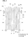
- the branch pipes 10 each have a circular section (refer to Fig. 4 ), has a plurality of parallel portions 11 arranged in parallel and a plurality of bent portions 15 connecting adjacent parallel portions 11 to each other, and is formed to have a meandering shape (S-shape) as illustrated in Fig. 3 .
- the parallel portions 11 are arranged in parallel to each other.
- Each of the bent portions 15 is formed to have a semi-circular arc shape (central angle: 180°). Note that the term "parallel" does not necessarily mean being parallel in a strict meaning in terms of geometry, is not limited to being exactly parallel, but covers a range that is substantially regarded as being parallel.
- circular shape and semi-circular arc shape do not necessarily mean a circular shape and a semi-circular arc shape in a strict meaning in terms of geometry, are not limited to a perfect circular shape and a perfect semi-circular arc shape, but cover ranges that are substantially regarded as a circular shape and a semi-circular arc shape, respectively.
- the parallel portions 11 are each a straight-line portion that is linearly formed is described as an example.
- the parallel portions 11 are not limited to such straight-line portions and may be, for example, curved-line portions that are curved or wavy-line portions formed to have a wavy-line shape.
- Each of the branch pipes 10 includes a meandering portion in which a plurality of parallel portions 11 and a plurality of bent portions 15 are integrally molded so as to be alternately connected.
- the branch pipe 10 has three linear parallel portions 11a to 11c and two bent portions 15a and 15b, and the linear parallel portions 11a to 11c and the bent portions 15a and 15b are alternately connected to form an S-shaped meandering portion.
- the branch pipe 10 is manufactured by rotational molding.
- the branch pipe 10 satisfies a ratio (X/D) of a center-to-center distance X to an outer diameter D of 1.2 or more and 2.5 or less where D (mm) represents an outer diameter of the branch pipe 10 and X (mm) represents a distance between centers of parallel portions 11 adjacent to each other (refer to Figs. 3 and 4 ).
- the term "center-to-center distance” refers to the maxim distance between center lines of adjacent parallel portions 11 in the direction in which the parallel portions 11 are arranged in parallel (maximum center-to-center distance).
- the pipe unit 1 (refer to Fig. 1 ) including a plurality of branch pipes 10 can be made compact as a whole.
- the ratio X/D is 1.2 or more, the parallel portions 11 are arranged at intervals, and a gap is formed between the parallel portions 11. Therefore, the heat dissipation effect of the branch pipes 10 is easily secured. Consequently, an increase in the temperature of an electrolyte flowing through the branch pipes 10 can be suppressed.
- the ratio X/D is preferably, for example, 1.5 or more and 2.0 or less.
- branch pipe 10 preferably satisfies any one of the following requirements.
- the branch pipe 10 has an inner peripheral surface having a surface roughness (arithmetical mean roughness Ra) of 6.3 ⁇ m or less, the flow resistance of an electrolyte can be reduced.
- the branch pipe 10 has an outer diameter of 30 mm or more, the flow path area of an electrolyte is easily secured.
- the outer diameter is 50 mm or less, the branch pipe 10 is easily made compact.
- the outer diameter is 50 mm or less, a shunt current loss due to an increase in the flow path area is easily suppressed.
- the outer diameter is more preferably, for example, 40 mm or less.
- the branch pipe 10 has a thickness of 1 mm or more, permeation of oxygen is reduced to easily suppress entry of oxygen. Consequently, degradation of an electrolyte due to reaction with oxygen is easily suppressed, and a reduction in the battery capacity is easily suppressed.
- the thickness is 5 mm or less, the flow path area is easily secured while an increase in the outer diameter is suppressed.
- the thickness is more preferably 3 mm or less.
- the parallel portions 11 of the branch pipe 10 each have a length of, for example, 900 mm or more and 1,500 mm or less.
- the parallel portion 11 has a length of 900 mm or more, the branch pipe 10 has a long total length, and a shunt current loss is easily and effectively suppressed.
- the parallel portion 11 has a length of 1,500 mm or less, the dimension of the branch pipe 10 in the direction along the parallel portion 11 can be suppressed.
- the branch pipe 10 is formed of a resin that does not react with an electrolyte because the electrolyte flow through the branch pipe 10.
- the resin include polyethylene resins, polypropylene resins, and polyvinyl chloride resins.
- polyethylene resins or polypropylene resins are preferable from the viewpoint of, for example, resistance to electrolytes, moldability, and mechanical strength.
- the branch pipe 10 is formed of a polyethylene resin (PE).
- the other end of the branch pipe 10 (end on the side opposite to the side to which the trunk pipe 20 is connected) is bent downward (refer to Figs. 1 and 5 ) in the assembles state of the pipe unit 1.
- the branch pipes 10a to 10d have, on the other ends thereof, flanges 31 for connecting to supply ports and drainage ports (not shown) of battery elements.
- each of the flanges 31 has a cylindrical portion 31a into which the other end of the branch pipe 10 is inserted.
- the flange 31 illustrated in this example is thermally fused to the other end of the branch pipe 10 in a state in which the other end of the branch pipe 10 is inserted into the cylindrical portion 31a.
- the flange 31 can be formed by using the same resin (for example, a polyethylene resin or a polypropylene resin) as that used for the branch pipe 10.
- the flange 31 is formed of the same polyethylene resin as that used for the branch pipe 10.
- the flange 31 is formed as a separate component from the branch pipe 10 and attached to the end of the branch pipe 10 by thermal fusion.
- the flange 31 is not limited thereto.
- the flange 31 may be integrally molded at the end of the branch pipe 10 by rotational molding. When the flange 31 is integrally molded, there is no seam between the flange 31 and the end of the branch pipe 10. Accordingly, the risk of liquid leakage can be further reduced, and reliability improves.
- the trunk pipe 20 is a linear pipe having a circular section (refer to Figs. 3 and 5 ).
- the trunk pipe 20 is formed of a resin, similarly to the branch pipes 10, and formed by using the resin described above (for example, a polyethylene resin or a polypropylene resin).
- a plurality of branch connecting portions 21 to which the one-ends of the branch pipes 10a to 10d are connected are integrally molded on the peripheral surface of the trunk pipe 20.
- the branch connecting portions 21 project from the peripheral surface of the trunk pipe 20 and arranged in the longitudinal direction of the trunk pipe 20. In this example, the one end of each of the branch pipes 10 is bent upward (refer to Figs. 2 and 5 ).
- the one-ends of the branch pipes 10a to 10d and ends of the branch connecting portions 21 of the trunk pipe 20 are disposed so as to face each other and thermally fused together in this state. Consequently, the branch pipes 10 are connected to the trunk pipe 20 to form the pipe unit 1 illustrated in Fig. 1 .
- the trunk pipe 20 is formed of the same polyethylene resin as that used for the branch pipes 10, and the trunk pipe 20 is manufactured by rotational molding.
- the surface roughness of the inner peripheral surface of the trunk pipe 20 and the thickness of the trunk pipe 20 are preferably the same as those of the branch pipes 10.
- the trunk pipe 20 may have an inner peripheral surface having a surface roughness (arithmetical mean roughness Ra) of 6.3 ⁇ m or less and have a thickness of 1 mm or more and 5 mm or less, preferably 3 mm or less.
- the trunk pipe 20 has, on each end thereof, a flange 32 for connecting to another trunk pipe.
- the flange 32 has a cylindrical portion 32a into which an end of the trunk pipe 20 is inserted.
- the flange 32 illustrated in this example is thermally fused to an end of the trunk pipe 20 in a state in which the end of the trunk pipe 20 is inserted into the cylindrical portion 32a.
- the flange 32 can be formed by using the same resin (for example, a polyethylene resin or a polypropylene resin) as that used for the trunk pipe 20.
- the flange 32 is formed of the same polyethylene resin as that used for the trunk pipe 20.
- the flange 32 is formed as a separate component from the trunk pipe 20 and attached to each end of the trunk pipe 20 by thermal fusion.
- the flange 32 is not limited thereto.
- the flange 32 may be integrally molded at the end of the trunk pipe 20 by rotational molding. When the flange 32 is integrally molded, there is no seam between the flange 32 and the end of the trunk pipe 20. Accordingly, the risk of liquid leakage can be further reduced, and reliability improves.
- the redox flow battery pipe (branch pipe 10) according to the above embodiment has the following advantageous effects.
- the redox flow battery pipe according to the above embodiment can be suitably used as a shunt killer pipe of a redox flow battery.
- the pipe unit 1 according to the above embodiment has the following advantageous effects.
- the redox flow battery according to the above embodiment has the following advantageous effects.
- a method for manufacturing an RF battery pipe (branch pipe) according to an embodiment will be described with reference to Figs. 6 and 7 .
- a branch pipe 10 (refer to Fig. 3 ) can be manufactured by a method for manufacturing a RF battery pipe according to an embodiment, the method including a material-feeding step, a rotational molding step, and a removal step.
- the steps in the method for manufacturing an RF battery pipe will be described in detail.
- the material-feeding step is a step of feeding a resin 60 into a mold 50, as illustrated in Fig. 6 .
- a meandering cavity 50c in which a plurality of parallel portions 51 and a plurality of bent portions 55 are alternately connected is formed in the mold 50.
- the cavity 50c is formed to have a meandering shape (S-shape) so as to correspond to the shape of the branch pipe 10 (refer to Fig. 3 ).
- the cavity 50c is a hole having a circular section (refer to the upper drawing of Fig. 7 ) and has three linear parallel portions 51a to 51c arranged in parallel and two bent portions 55a and 55b connecting adjacent parallel portions 51 to each other in plan view, as illustrated in Fig. 6 .
- the cavity 50c is formed in a continuous, meandering manner such that the parallel portions 51a to 51c and the bent portions 55a and 55b are alternately connected.
- the mold 50 has a resin feed port 50i that communicates with the cavity 50c.
- the resin 60 used as the material is a powdery resin and is a polyethylene resin in this example.
- the mold 50 has a halved structure including an upper mold 50A and a lower mold 50B and can be opened and closed in the up-down direction.
- a groove having a semi-circular section that forms the cavity 50c is formed in a meandering manner.
- the mold 50 is configured so that the cavity 50c is formed by closing the upper mold 50A and the lower mold 50B downward and upward, respectively.
- the mold 50 is configured so as to form a cavity 50c having a flange-shaped recess (not shown) corresponding to the shape of the flange 31 at an end position of a parallel portion 51 on which the flange 31 is to be formed.
- the resin 60 in the cavity 50c is subjected to rotational molding to form a meandering pipe in which a plurality of parallel portions and a plurality of bent portions are integrally molded so as to be alternately connected.
- the molding is performed by rotating the mold 50 (refer to Fig. 6 ) while heating so that the resin 60 in the cavity 50c is melted and adheres to a wall surface of the cavity 50c, and subsequently cooling the mold 50 while rotating so as to cover the wall surface of the cavity 50c with the resin 60.
- the rotational molding is preferably performed under conditions of biaxial rotation in which the mold is subjected to a planetary motion by a biaxial motion.
- the heating method is preferably a medium circulation method in which heating is performed by directly circulating a heat medium through the mold.
- the rotational speed during the rotational molding is appropriately determined.
- both a primary axis and a secondary axis are rotated at a rotational speed of 1 rpm or more and 100 rpm or less.
- a known rotational molding machine can be used in the rotational molding.
- the removal step is a step of removing the resulting molded article of the pipe from the mold 50. Specifically, as illustrated in the lower drawing of Fig. 7 , the upper mold 50A and the lower mold 50B are opened upward and downward, respectively, and the branch pipe 10 is removed.
- the method for manufacturing a redox flow battery pipe according to the above embodiment has the following advantageous effects.
- a meandering pipe having a relatively small distance between the centers of the parallel portions adjacent to each other relative to the outer diameter of the pipe can be easily manufactured.
- the inventors of the present invention manufactured a meandering pipe on an experimental basis by bending a pipe to form a bent portion. According to the results, it was difficult to form a bent portion by bending so as to satisfy a ratio X/D of 2.5 or less. For example, buckling occurred, and such a pipe could not be stably formed with high accuracy.
- molding is performed by causing a molten resin to adhere to a wall surface of a cavity, and gradually forming a layer of the resin. Accordingly, internal stress is unlikely to remain compared with another molding method such as injection molding. Furthermore, since no pressure is applied during molding, residual stress is small. Therefore, a high impact resistance is obtained, and stress cracking is unlikely to occur.
- Injection molding is typically employed for molding a resin, and a core is used when a pipe is molded.
- injection molding since the inner peripheral surface of the pipe comes in contact with the core during injection molding, surface properties of the inner peripheral surface of the pipe may be degraded by contact with the core.
- rotational molding a layer of a resin is gradually formed on a wall surface of a cavity as described above, and therefore, the inner peripheral surface of the pipe is a free surface during rotational molding. Accordingly, a smooth inner peripheral surface is easily obtained, and the surface roughness Ra of the inner peripheral surface of the pipe can be 6.3 ⁇ m or less.
- the inner peripheral surface of the pipe has a surface roughness of 6.3 ⁇ m or less, the flow resistance of an electrolyte flowing through the pipe can be expected to be reduced.
- a sectional shape may become flat in the bent portion, and the sectional shape of the bent portion may be deformed.
- a pipe having a circular section it is difficult to maintain the sectional shape of the bent portion to be a circular shape. Consequently, the circularity may differ between the parallel portion and the bent portion.
- deformation of the sectional shape of the bent portion does not occur. Accordingly, the same sectional shape can be maintained from the parallel portion to the bent portion, and the circularity is maintained in the parallel portion and the bent portion.
- the flow resistance of an electrolyte can be expected to be reduced.
- a trunk pipe 20 may be molded integrally with branch pipes 10.
- a pipe unit 1A according to another embodiment will be described with reference to Figs. 8 to 10 .
- components the same as those of the pipe unit 1 according to the above embodiment are assigned the same reference signs, and descriptions thereof are omitted. The difference will be mainly described.
- a pipe unit 1A includes a trunk pipe 20 and a plurality of branch pipes 10 branching off from the trunk pipe 20.
- four branch pipes 10a to 10d branch off from the trunk pipe 20, and one end of each of the branch pipes 10a to 10d is connected to the trunk pipe 20.
- the trunk pipe 20 is located in a direction along parallel portions 11 of the branch pipes 10, and the branch pipes 10 (parallel portions 11) and the trunk pipe 20 are disposed on the same plane so as not to overlap with each other in plan view.
- the trunk pipe 20 and the branch pipes 10 are integrally molded.
- the pipe unit 1A is manufactured by, for example, integrally molding the trunk pipe 20 and the branch pipes 10 by rotational molding using, as a material, a resin such as a polyethylene resin, a polypropylene resin, or a polyvinyl chloride resin.
- a mold used in this case has a cavity for integrally molding the trunk pipe 20 and the branch pipes 10.
- a flange 31 may be integrally molded at an end of each of the branch pipes 10, and a flange 32 may be integrally molded at an end of the trunk pipe 20, as described in the above embodiment.
- the trunk pipe 20 and the branch pipes 10 are integrally molded, there is no seam between the trunk pipe 20 and each of the branch pipes 10. Thus, the risk of liquid leakage can be further reduced, and reliability improves.
- the trunk pipe and the branch pipes are integrally molded, an operation for connecting the trunk pipe to the branch pipes is not necessary, and therefore, productivity improves.
- the pipe unit 1A is applied to a pipe through which an electrolyte is circulated and which is included in the redox flow battery according to the above embodiment, the risk of liquid leakage of the pipe can be further reduced, and reliability can be further enhanced.
Landscapes
- Life Sciences & Earth Sciences (AREA)
- Engineering & Computer Science (AREA)
- Manufacturing & Machinery (AREA)
- Sustainable Development (AREA)
- Sustainable Energy (AREA)
- Chemical & Material Sciences (AREA)
- Chemical Kinetics & Catalysis (AREA)
- Electrochemistry (AREA)
- General Chemical & Material Sciences (AREA)
- Fuel Cell (AREA)
Description
- The present invention relates to a redox flow battery pipe, a method for manufacturing a redox flow battery pipe, a pipe unit, and a redox flow battery.
- The present application claims priority from Japanese Patent Application No.
2016-104716 filed on May 25, 2016 - In recent years, in order to cope with global warming, introduction of power generation using natural energy (so-called renewable energy), such as solar photovoltaic power generation or wind power generation, has been promoted worldwide. The output of such power generation depends on natural conditions, such as weather. Accordingly, it is expected that when such power generation using natural energy is introduced on a large scale, problems, such as difficulties in maintaining frequencies and voltages, may occur during the operation of power systems. As a countermeasure for such problems, it is expected that large-capacity secondary batteries are installed so that, for example, smoothing of variations in output, storage of surplus power, and supply of electricity during power shortage are achieved.
- One of large-capacity secondary batteries is a redox flow battery (RF battery) (refer to PTL 1). The RF battery supplies a positive electrolyte and a negative electrolyte to a battery element including a cell, which includes a positive electrode, a negative electrode, and a membrane disposed between the electrodes, so as to perform charging and discharging. Aqueous solutions containing metal ions, such as vanadium (V) ions, whose valence is changed by oxidation-reduction are used as the electrolytes.
Figure 11 is an operating principle diagram of a vanadium-basedRF battery 300 in which vanadium electrolytes containing V ions are used as a positive electrolyte and a negative electrolyte. In acell 110 illustrated inFig. 11 , the solid-line arrows indicate a charging reaction, and the dashed-line arrows indicate a discharging reaction. - The
RF battery 300 includes abattery element 100. Thebattery element 100 includes acell 110 including apositive electrode cell 112a that contains apositive electrode 102a therein, anegative electrode cell 112b that contains anegative electrode 102b therein, and amembrane 101 disposed between the electrode cells. TheRF battery 300 includes tanks 120 (apositive electrolyte tank 120a and anegative electrolyte tank 120b) that store a positive electrolyte and a negative electrolyte, respectively, and electrolyte flow paths 130 (a positiveelectrolyte flow path 130a and a negativeelectrolyte flow path 130b) through which the electrolytes are circulated between thetanks 120 and the battery element 100 (cell 110). Theelectrolyte flow paths 130 includepipes tanks 120 and thebattery element 100 and through which the electrolytes flow. Thetanks 120 and thebattery element 100 are connected together with thepipes pipes 131 are supply pipes through which the electrolytes are supplied from thetanks 120 to the cell 110 (thepositive electrode cell 112a and thenegative electrode cell 112b), and thepipes 132 are return pipes through which the electrolytes are returned from thecell 110 to thetanks 120. The electrolyte flow paths 130 (thepipes 131 in this example) are provided with pumps 140 (apositive electrolyte pump 140a and anegative electrolyte pump 140b) for pumping their corresponding electrolytes, respectively. - In general, the
battery element 100 is used in the form of a cell stack in which a plurality ofcells 110 each including thepositive electrode 102a (positive electrode cell 112a), anegative electrode 102b (negative electrode cell 112b), and amembrane 101 disposed between the electrodes are stacked.Figure 12 is a schematic structural view of a cell stack.Cell frames 210 each including abipolar plate 211 and aframe body 212 provided on the outer periphery of thebipolar plate 211 so as to be integrated with each other are used in acell stack 200. Thecell stack 200 is constituted by stacking a plurality ofcells 110 with thecell frames 210 therebetween, thecells 110 each including apositive electrode 102a, amembrane 101, and anegative electrode 102b that overlap, sandwiching the resulting layered body from both sides thereof using twoend plates 220, and fastening the layered body. Specifically, a negative electrode (negative electrode cell) and a positive electrode (positive electrode cell) ofadjacent cells 110 are disposed so as to sandwich a cell frame 210 (bipolar plate 211). Supply/drainage plates (not shown) each provided with a supply port through which an electrolyte is supplied and a drainage port through which the electrolyte is drained are disposed on thecell stack 200. Thepipes Fig. 11 ) of the electrolytes are connected to the supply port and the drainage port, respectively. - PTL 1: Japanese Unexamined Patent Application Publication No.
2013-206566 - A redox flow battery pipe according to the present disclosure is
a redox flow battery pipe which is disposed between a tank that stores an electrolyte and a battery element and through which the electrolyte flows, the pipe including
a plurality of parallel portions arranged in parallel and a plurality of bent portions connecting the parallel portions adjacent to each other,
wherein the pipe includes a meandering portion in which the parallel portions and the bent portions are integrally molded so as to be alternately connected, and
a ratio of a center-to-center distance X to an outer diameter D satisfies 1.2 or more and 2.5 or less where D represents an outer diameter and X represents a distance between centers of the parallel portions adjacent to each other. - A method for manufacturing a redox flow battery pipe according to the present disclosure includes
a material-feeding step of feeding a resin into a mold having a meandering cavity in which a plurality of parallel portions and a plurality of bent portions are alternately connected,
a rotational molding step of subjecting the resin in the cavity to rotational molding to mold a meandering pipe in which a plurality of parallel portions and a plurality of bent portions are integrally molded so as to be alternately connected, and
a removal step of removing a molded article of the pipe from the mold. - A pipe unit according to the present disclosure is
a pipe unit which is disposed between a tank that stores an electrolyte and a battery element and through which the electrolyte flows, the pipe unit including
a trunk pipe connected to the tank side and a plurality of branch pipes branching off from the trunk pipe and connected to the battery element side,
wherein at least part of the branch pipes is the redox flow battery pipe according to the present disclosure, and
the trunk pipe and the branch pipes are integrally molded. - A redox flow battery according to the present disclosure is
a redox flow battery including a plurality of battery elements, a tank that stores an electrolyte, and a pipe through which the electrolyte is circulated between the tank and the battery elements,
wherein the pipe includes a trunk pipe connected to the tank side and a plurality of branch pipes branching off from the trunk pipe and connected to the battery element side, and
at least part of the branch pipes is the redox flow battery pipe according to the present disclosure. -
- [
Fig. 1] Figure 1 is a schematic perspective view illustrating a pipe unit including a redox flow battery pipe according to an embodiment. - [
Fig. 2] Figure 2 is an exploded perspective view that schematically illustrates a pipe unit including a redox flow battery pipe according to an embodiment. - [
Fig. 3] Figure 3 is a schematic bottom view illustrating a pipe unit including a redox flow battery pipe according to an embodiment. - [
Fig. 4] Figure 4 is a schematic sectional view of the redox flow battery pipe taken along line IV-IV inFig. 3 . - [
Fig. 5] Figure 5 is a schematic side view of the pipe unit illustrated inFig. 3 . - [
Fig. 6] Figure 6 is a schematic plan view illustrating a material-feeding step in a method for manufacturing a redox flow battery pipe according to an embodiment. - [
Fig. 7] Figure 7 includes schematic sectional views of a mold taken along line VII-VII inFig. 6 . - [
Fig. 8] Figure 8 is a schematic perspective view illustrating a pipe unit according to another embodiment. - [
Fig. 9] Figure 9 is a schematic bottom view illustrating a pipe unit according to another embodiment. - [
Fig. 10] Figure 10 is a schematic side view of the pipe unit illustrated inFig. 9 . - [
Fig. 11] Figure 11 is a schematic view illustrating a redox flow battery. - [
Fig. 12] Figure 12 is a schematic view illustrating a cell stack. - In general, a large-capacity RF battery includes a plurality of battery elements (a cell stack) and is configured so that a pipe through which an electrolyte flows is branched between a tank and each of the battery elements so as to transport the electrolyte between the single tank and the plurality of battery elements. In this case, a pipe (may be referred to as a "pipe unit") that includes a trunk pipe connected to the tank side and a plurality of branch pipes that branch off from the trunk pipe and are connected to the corresponding battery element side is used as the pipe that forms an electrolyte flow path of the RF battery. The pipes used in an RF battery are formed of a resin that does not react with electrolytes, typically, a polyvinyl chloride resin (PVC) because the pipes come in direct contact with the electrolytes.
- When the above pipe that includes a trunk pipe and branch pipes is used for the electrolyte flow path of an RF battery, a common electrolyte flows from the trunk pipe to the battery elements through the branch pipes, and consequently, the battery elements adjacent to each other are electrically connected to each other through the electrolyte. In the RF battery, since there are manufacturing variations in the battery elements, a potential difference may be generated between adjacent battery elements. A shunt current due to this potential difference flows in the electrolyte that flows through the pipe (the trunk pipe and the branch pipes), thereby generating a loss, for example, generation of heat from the electrolyte. As a countermeasure for this, in order to increase the electrical resistance of the electrolyte flowing in the pipe, it is effective to reduce the flow path area (diameter) of each of the branch pipes connected to the battery element side and to increase the total length of the branch pipes.
- Hitherto, in order to reduce the installation space of the pipe in an RF battery, a meandering (S-shaped) pipe (may be referred to as a "shunt killer pipe") in which a plurality of straight-line portions and a plurality of bent portions are alternately connected has been used as a branch pipe from the viewpoint of making the pipe compact as a whole. The term "meandering shape" refers to a shape that includes at least one meandering portion formed by three parallel portions (herein, straight-line portions) arranged in parallel and two bent portions each connecting adjacent parallel portions to each other. In this meandering pipe, on both end sides in a direction along the straight-line portions, a bent portion connecting two adjacent straight-line portions to each other and an end of the remaining one straight-line portion among the three straight-line portions are located adjacent to each other in a direction in which the straight-line portions are arranged in parallel.
- In existing branch pipes, a bent portion is formed by connecting pipes to each other with a joint therebetween or by bending a pipe. In the case of using a joint, there may be a problem of an increase in the risk of liquid leakage due to, for example, defects of joint assembly or bonding defects in a portion where the joint is connected to a pipe. In addition, the use of a joint is disadvantageous in that the connection operation takes a long time. On the other hand, in the case of bending, the risk of liquid leakage can be reduced because no joint is used in the bent portion. However, since the bending is usually performed by hand work, it is difficult to stably form the bent portion with high accuracy, resulting in an increase in the cost.
- Recently, there have been growing demands for a reduction in the size of a redox flow battery, and the realization of a more compact pipe has been strongly desired. In order to make a pipe compact, in a branch pipe, it is necessary to make straight-line portions closer to each other, and it is desirable to reduce the distance between the centers of straight-line portions adjacent to each other. However, reducing the distance between the centers of straight-line portions adjacent to each other (that is, reducing the radius of curvature of a bent portion) by bending is limited from the industrial viewpoint. Therefore, in practice, it is difficult to manufacture a meandering branch pipe having a small distance between the centers of straight-line portions adjacent to each other relative to the outer diameter of the pipe.
- In the case where the distance between the centers of straight-line portions adjacent to each other is reduced, a bent portion connecting the two adjacent straight-line portions and an end of the remaining one straight-line portion are adjacent and close to each other. Therefore, when a bent portion is formed by bending a pipe, there may be technical problems, for example, a problem of the arrangement of a processing jig and a problem in that an end of the straight-line portion that does not subjected to bending is also heated. In view of this, hitherto, a meandering branch pipe having a small distance between the centers of straight-line portions adjacent to each other has been manufactured by preparing two pipes that are bent to have a J-shape, and connecting the J-shaped pipes to each other with a joint therebetween to form a meandering shape (S-shape). Accordingly, in the existing branch pipe, it is difficult to realize both a reduction in the risk of liquid leakage and manufacturing of a compact pipe.
- Accordingly, an object of the present disclosure is to provide a redox flow battery pipe and a pipe unit having a low risk of liquid leakage and capable of being made compact in size. Another object is to provide a method for manufacturing a redox flow battery pipe, the method capable of industrially stably manufacturing, with high accuracy, a meandering pipe in which a plurality of parallel portions and a plurality of bent portions are integrally molded so as to be alternately connected. Furthermore, another object is to provide a redox flow battery in which the risk of liquid leakage of a pipe is low and an installation space of the pipe can be reduced.
- According to the redox flow battery pipe and the pipe unit, the risk of liquid leakage is low, and the sizes of the pipe and the pipe unit can be made compact. According to the method for manufacturing a redox flow battery pipe, a meandering pipe in which a plurality of parallel portions and a plurality of bent portions are integrally molded so as to be alternately connected can be industrially stably manufactured with high accuracy. According to the redox flow battery, the risk of liquid leakage of a pipe is low, and an installation space of the pipe can be reduced.
- The inventors of the present invention found that a meandering pipe in which a plurality of parallel portions and a plurality of bent portions are alternately connected can be integrally molded by manufacturing a redox flow battery pipe (branch pipe) by rotational molding. In rotational molding, since the molding is performed by using a mold, the restriction of the radius of curvature of the bent portions is small, and therefore, the distance between the centers of the parallel portions adjacent to each other relative to the outer diameter of the pipe can be reduced. Hereinafter, embodiments of the present invention will be listed and described.
- (1) A redox flow battery pipe according to an embodiment of the present invention is
a redox flow battery pipe which is disposed between a tank that stores an electrolyte and a battery element and through which the electrolyte flows, the pipe including
a plurality of parallel portions arranged in parallel and a plurality of bent portions connecting the parallel portions adjacent to each other,
wherein the pipe includes a meandering portion in which the parallel portions and the bent portions are integrally molded so as to be alternately connected, and
a ratio of a center-to-center distance X to an outer diameter D satisfies 1.2 or more and 2.5 or less where D represents an outer diameter and X represents a distance between centers of the parallel portions adjacent to each other.
Since the redox flow battery pipe includes a meandering portion in which a plurality of parallel portions and a plurality of bent portions are integrally molded so as to be alternately connected, a long total length of the pipe can be realized to reduce a loss due to a shunt current (shunt current loss). Since the plurality of parallel portions and the plurality of bent portions are integrally molded so as to be alternately connected, the pipe is seamless and has no connecting portion with a joint or bonding. Thus, the redox flow battery pipe has a low risk of liquid leakage and high reliability.
Since the ratio (X/D) of the distance X (mm) between the centers of the parallel portions adjacent to each other to the outer diameter D (mm) is 2.5 or less, the parallel portions are close to each other, and the pipe can be made compact. Specifically, the dimension of the pipe in a width direction (a direction in which the parallel portions are arranged in parallel) can be reduced. Accordingly, the redox flow battery pipe has a low risk of liquid leakage and can be made compact. Since the ratio X/D is 1.2 or more, the parallel portions are arranged at intervals, and a gap is formed between the parallel portions. Therefore, the heat dissipation effect of the pipe is easily secured. Consequently, an increase in the temperature of the electrolyte can be suppressed. - (2) According to an embodiment of the redox flow battery pipe, the parallel portions may be straight-line portions.
The parallel portions may be, besides the straight-line portions formed to have a straight-line shape, for example, curved-line portions (curved portions) formed to have a curved-line shape or wavy-line portions formed to have a wavy-line shape. When the parallel portions are straight-line portions having a straight -line shape, the pipe can be made more compact. When the parallel portions are, for example, curved-line portions (curved portions) or wavy-line portions, the total length of the pipe can be made longer than that in the straight-line portions to further reduce the shunt current loss. - (3) According to an embodiment of the redox flow battery pipe, the pipe may have an inner peripheral surface having a surface roughness of 6.3 µm or less.
When the inner peripheral surface of the redox flow battery pipe has a surface roughness of 6.3 µm or less, the flow resistance of the electrolyte can be reduced. The term "surface roughness" used herein refers to the arithmetical mean roughness (Ra) specified in JIS B 0601:2001. - (4) According to an embodiment of the redox flow battery pipe, the pipe may have an outer diameter of 30 mm or more and 50 mm or less.
When the outer diameter of the redox flow battery pipe is 30 mm or more, the flow path area of the electrolyte is easily ensured. When the outer diameter is 50 mm or less, the pipe is easily made compact. - (5) According to an embodiment of the redox flow battery pipe, the pipe may have a thickness of 1 mm or more and 5 mm or less.
When the thickness of the redox flow battery pipe is 1 mm or more, permeation of oxygen is reduced to easily suppress entry of oxygen. Consequently, degradation of the electrolyte due to reaction with oxygen is easily suppressed, and a reduction in the battery capacity is easily suppressed. When the thickness is 5 mm or less, the flow path area is easily secured while an increase in the outer diameter is suppressed. - (6) According to an embodiment of the redox flow battery pipe, the pipe may be formed of at least one resin selected from a polyethylene resin, a polypropylene resin, and a polyvinyl chloride resin.
A polyethylene resin (PE), a polypropylene resin (PP), and a polyvinyl chloride resin (PVC) have resistance to electrolytes and do not react with the electrolytes even when any of these resins comes in direct contact with the electrolytes. When the redox flow battery pipe is formed of a thermoplastic resin such as a polyethylene resin, a polypropylene resin, or a polyvinyl chloride resin and a component such as a flange is attached to an end of the pipe, the component can be connected by thermal fusion. When the pipe and the component are thermally fused to each other, liquid leakage is unlikely to occur from the connecting portion, and high reliability is achieved. In this case, the component is also preferably formed of the same resin as the polyethylene resin, the polypropylene resin, the polyvinyl chloride resin, or the like. - (7) According to an embodiment of the redox flow battery pipe, a flange for connecting to the battery element may be integrally molded at an end to be connected to the battery element side.
When the redox flow battery pipe has a flange at an end to be connected to the battery element side, the redox flow battery pipe can be easily connected to the battery element. The flange can be attached to the end of the pipe by, for example, bonding or thermal fusion. However, when the flange is molded integrally with the end of the pipe, there is no seam between the flange and the end of the pipe. Thus, the risk of liquid leakage can be further reduced, and reliability improves. Furthermore, when the flange is integrally molded, an operation for connecting the flange to the end of the pipe is not necessary, and therefore, productivity improves. - (8) A method for manufacturing a redox flow battery pipe according to an embodiment of the present invention includes
a material-feeding step of feeding a resin into a mold having a meandering cavity in which a plurality of parallel portions and a plurality of bent portions are alternately connected,
a rotational molding step of subjecting the resin in the cavity to rotational molding to mold a meandering pipe in which a plurality of parallel portions and a plurality of bent portions are integrally molded so as to be alternately connected, and
a removal step of removing a molded article of the pipe from the mold.
According to the manufacturing method, a meandering pipe in which a plurality of parallel portions and a plurality of bent portions are integrally molded so as to be alternately connected can be molded by rotational molding of a resin using a mold having a meandering cavity. Since this meandering pipe is an integrally molded article, is seamless, and has no connecting portion with a joint or bonding, the pipe has a low risk of liquid leakage. Accordingly, the pipe can be suitably used as a redox flow battery pipe (branch pipe). In the manufacturing method, since the meandering pipe is integrally molded by rotational molding, unlike existing methods, an operation of assembling a joint or bonding, or bending by hand work is not necessary. Thus, the pipe can be industrially stably manufactured with high accuracy to realize a reduction in the cost.
In the case of rotational molding, the distance between the centers of the parallel portions adjacent to each other can be made smaller (that is, the radius of curvature of the bent portions can be made smaller) than that in the case of bending. Therefore, a meandering pipe having a relatively small distance between the centers of the parallel portions adjacent to each other relative to the outer diameter of the pipe can be easily manufactured. For example, it is also easy to manufacture a meandering pipe in which the ratio (X/D) of the distance X (mm) between the centers of the parallel portions adjacent to each other to the outer diameter D (mm) satisfies 1.2 or more and 2.5 or less. - (9) A pipe unit according to an embodiment of the present invention is
a pipe unit which is disposed between a tank that stores an electrolyte and a battery element and through which the electrolyte flows, the pipe unit including
a trunk pipe connected to the tank side and a plurality of branch pipes branching off from the trunk pipe and connected to the battery element side,
wherein at least part of the branch pipes is the redox flow battery pipe according to any one of (1) to (7) above, and
the trunk pipe and the branch pipes are integrally molded.
In the pipe unit, at least part of the branch pipes that form a pipe through which an electrolyte is circulated is the above-described redox flow battery pipe according to an embodiment of the present invention. Therefore, the pipe unit has a low risk of liquid leakage of the pipe and high reliability. Furthermore, since the trunk pipe and the branch pipes are integrally molded, there is no seam between the trunk pipe and each of the branch pipes. Thus, the risk of liquid leakage can be further reduced, and reliability improves. In addition, since the trunk pipe and the branch pipes are integrally molded, an operation for connecting the trunk pipe to the branch pipes is not necessary, and thus productivity improves. The redox flow battery pipe described above has a small dimension in the width direction and is compact. Thus, the pipe unit that includes the redox flow battery pipe as each of the branch pipes can be made compact. Accordingly, the pipe unit has a low risk of liquid leakage and can be made compact.
The pipe unit in which the trunk pipe and the branch pipes are integrally molded can be manufactured by rotational molding. The pipe unit may be formed of, for example, at least one resin selected from a polyethylene resin, a polypropylene resin, and a polyvinyl chloride resin. - (10) A redox flow battery according to an embodiment of the present invention is
a redox flow battery including a plurality of battery elements, a tank that stores an electrolyte, and a pipe through which the electrolyte is circulated between the tank and the battery elements,
wherein the pipe includes a trunk pipe connected to the tank side and a plurality of branch pipes branching off from the trunk pipe and connected to the battery element side, and
at least part of the branch pipes is the redox flow battery pipe according to any one of (1) to (7) above.
In the redox flow battery, at least part of the branch pipes that form a pipe through which an electrolyte is circulated is the above-described redox flow battery pipe according to an embodiment of the present invention. Therefore, the redox flow battery has a low risk of liquid leakage of the pipe and high reliability. The redox flow battery pipe has a small dimension in the width direction and is compact. Accordingly, when the redox flow battery includes the redox flow battery pipe as the branch pipes, the whole of the pipe (pipe unit) can be made compact. According to the redox flow battery, the installation space of the pipe can be reduced, and the size of the battery can be reduced. - (11) According to an embodiment of the redox flow battery, the trunk pipe and the branch pipes may be thermally fused together.
When the trunk pipe and the branch pipes are thermally fused together, liquid leakage is unlikely to occur from the portions where the trunk pipe is connected to the branch pipes, and high reliability is achieved. In this case, the trunk pipe and the branch pipes may be formed of, for example, a resin such as a polyethylene resin, a polypropylene resin, or a polyvinyl chloride resin. - (12) According to an embodiment of the redox flow battery, the trunk pipe and the branch pipes may be integrally molded.
- When the trunk pipe and the branch pipes are integrally molded, there is no seam between the trunk pipe and each of the branch pipes, the risk of liquid leakage can be further reduced, and reliability improves. In this case, the trunk pipe and the branch pipes may be, for example, integrally molded by rotational molding using a resin such as a polyethylene resin, a polypropylene resin, or a polyvinyl chloride resin.
- Specific examples of a redox flow battery pipe, a method for manufacturing a redox flow battery pipe, a pipe unit, and a redox flow battery according to embodiments of the present invention will be described. The same reference signs in the drawings denote the same parts. The present invention is not limited to the examples but is defined by the appended claims. The present invention is intended to cover all the modifications within the meaning and scope equivalent to those of the claims.
- First, a description will be made of an RF battery according to an embodiment in which an RF battery pipe according to an embodiment is used. The basic configuration of the RF battery according to the embodiment is the same as that of the
RF battery 300 that has been described with reference toFig. 11 and includesbattery elements 100,tanks 120 that store electrolytes, and electrolyte flow paths 130 (pipes 131 and 132) through which the electrolytes are circulated between thecorresponding tank 120 and thebattery elements 100. The RF battery according to the embodiment includes, as thebattery elements 100, a plurality of cell stacks each obtained by stacking a plurality ofcells 110. Each of thepipes corresponding tank 120 and thebattery elements 100 has one end that branches with respect to theindividual battery elements 100 and is constituted by, for example, apipe unit 1 including atrunk pipe 20 and a plurality ofbranch pipes 10 branching off from thetrunk pipe 20, as illustrated inFig. 1 . Thetrunk pipe 20 is connected to thetank 120 side, and thebranch pipes 10 are each connected to thebattery element 100 side. One of features of the RF battery according to the embodiment lies in that thebranch pipes 10 are each an RF battery pipe according to an embodiment described below. - The
pipe unit 1 according to the embodiment illustrated inFig. 1 includes atrunk pipe 20 and fourbranch pipes 10a to 10d branching off from thetrunk pipe 20. Thebranch pipes 10a to 10d are arranged in parallel in a direction orthogonal to a longitudinal direction of thetrunk pipe 20. As illustrated inFig. 2 , thepipe unit 1 is constituted by connecting one end of each of thebranch pipes 10a to 10d to thetrunk pipe 20. - An RF battery pipe according to an embodiment will be described with reference to
Figs. 1 to 5 . Herein, an RF battery pipe according to an embodiment will be described as a branch pipe while a description will be made of, as an example, a case where the RF battery pipe according to the embodiment is applied to each of the branch pipes described above. In the description below, a direction in whichbranch pipes 10 are arranged (a direction in whichparallel portions 11 are arranged in parallel) is defined as a width direction (left-right direction). With respect to a plane on which the branch pipes 10 (parallel portions 11) are arranged, the side on which atrunk pipe 20 is located is defined as a top, and the opposite side thereof is defined as a bottom. - The
branch pipes 10 each have a circular section (refer toFig. 4 ), has a plurality ofparallel portions 11 arranged in parallel and a plurality ofbent portions 15 connecting adjacentparallel portions 11 to each other, and is formed to have a meandering shape (S-shape) as illustrated inFig. 3 . Theparallel portions 11 are arranged in parallel to each other. Each of thebent portions 15 is formed to have a semi-circular arc shape (central angle: 180°). Note that the term "parallel" does not necessarily mean being parallel in a strict meaning in terms of geometry, is not limited to being exactly parallel, but covers a range that is substantially regarded as being parallel. The terms "circular shape" and "semi-circular arc shape" do not necessarily mean a circular shape and a semi-circular arc shape in a strict meaning in terms of geometry, are not limited to a perfect circular shape and a perfect semi-circular arc shape, but cover ranges that are substantially regarded as a circular shape and a semi-circular arc shape, respectively. In this embodiment, an embodiment in which theparallel portions 11 are each a straight-line portion that is linearly formed is described as an example. However, theparallel portions 11 are not limited to such straight-line portions and may be, for example, curved-line portions that are curved or wavy-line portions formed to have a wavy-line shape. - Each of the
branch pipes 10 includes a meandering portion in which a plurality ofparallel portions 11 and a plurality ofbent portions 15 are integrally molded so as to be alternately connected. In this example, thebranch pipe 10 has three linearparallel portions 11a to 11c and twobent portions parallel portions 11a to 11c and thebent portions branch pipe 10 is manufactured by rotational molding. - The
branch pipe 10 satisfies a ratio (X/D) of a center-to-center distance X to an outer diameter D of 1.2 or more and 2.5 or less where D (mm) represents an outer diameter of thebranch pipe 10 and X (mm) represents a distance between centers ofparallel portions 11 adjacent to each other (refer toFigs. 3 and4 ). The term "center-to-center distance" refers to the maxim distance between center lines of adjacentparallel portions 11 in the direction in which theparallel portions 11 are arranged in parallel (maximum center-to-center distance). When the ratio X/D is 2.5 or less, theparallel portions 11 are close to each other, and the dimension of thebranch pipe 10 in the width direction can be reduced. Since thebranch pipe 10 can be made compact, the pipe unit 1 (refer toFig. 1 ) including a plurality ofbranch pipes 10 can be made compact as a whole. When the ratio X/D is 1.2 or more, theparallel portions 11 are arranged at intervals, and a gap is formed between theparallel portions 11. Therefore, the heat dissipation effect of thebranch pipes 10 is easily secured. Consequently, an increase in the temperature of an electrolyte flowing through thebranch pipes 10 can be suppressed. The ratio X/D is preferably, for example, 1.5 or more and 2.0 or less. - Furthermore, the
branch pipe 10 preferably satisfies any one of the following requirements. - The surface roughness of an inner peripheral surface is 6.3 µm or less.
- The outer diameter is 30 mm or more and 50 mm or less.
- The thickness is 1 mm or more and 5 mm or less.
- When the
branch pipe 10 has an inner peripheral surface having a surface roughness (arithmetical mean roughness Ra) of 6.3 µm or less, the flow resistance of an electrolyte can be reduced. - When the
branch pipe 10 has an outer diameter of 30 mm or more, the flow path area of an electrolyte is easily secured. When the outer diameter is 50 mm or less, thebranch pipe 10 is easily made compact. When the outer diameter is 50 mm or less, a shunt current loss due to an increase in the flow path area is easily suppressed. The outer diameter is more preferably, for example, 40 mm or less. - When the
branch pipe 10 has a thickness of 1 mm or more, permeation of oxygen is reduced to easily suppress entry of oxygen. Consequently, degradation of an electrolyte due to reaction with oxygen is easily suppressed, and a reduction in the battery capacity is easily suppressed. When the thickness is 5 mm or less, the flow path area is easily secured while an increase in the outer diameter is suppressed. The thickness is more preferably 3 mm or less. - The
parallel portions 11 of thebranch pipe 10 each have a length of, for example, 900 mm or more and 1,500 mm or less. When theparallel portion 11 has a length of 900 mm or more, thebranch pipe 10 has a long total length, and a shunt current loss is easily and effectively suppressed. When theparallel portion 11 has a length of 1,500 mm or less, the dimension of thebranch pipe 10 in the direction along theparallel portion 11 can be suppressed. - The
branch pipe 10 is formed of a resin that does not react with an electrolyte because the electrolyte flow through thebranch pipe 10. Examples of the resin include polyethylene resins, polypropylene resins, and polyvinyl chloride resins. Among these, polyethylene resins or polypropylene resins are preferable from the viewpoint of, for example, resistance to electrolytes, moldability, and mechanical strength. In this example, thebranch pipe 10 is formed of a polyethylene resin (PE). - In this example, the other end of the branch pipe 10 (end on the side opposite to the side to which the
trunk pipe 20 is connected) is bent downward (refer toFigs. 1 and5 ) in the assembles state of thepipe unit 1. As illustrated inFig. 1 , thebranch pipes 10a to 10d have, on the other ends thereof,flanges 31 for connecting to supply ports and drainage ports (not shown) of battery elements. As illustrated inFig. 5 , each of theflanges 31 has acylindrical portion 31a into which the other end of thebranch pipe 10 is inserted. Theflange 31 illustrated in this example is thermally fused to the other end of thebranch pipe 10 in a state in which the other end of thebranch pipe 10 is inserted into thecylindrical portion 31a. Theflange 31 can be formed by using the same resin (for example, a polyethylene resin or a polypropylene resin) as that used for thebranch pipe 10. In this example, theflange 31 is formed of the same polyethylene resin as that used for thebranch pipe 10. In this example, theflange 31 is formed as a separate component from thebranch pipe 10 and attached to the end of thebranch pipe 10 by thermal fusion. However, theflange 31 is not limited thereto. For example, theflange 31 may be integrally molded at the end of thebranch pipe 10 by rotational molding. When theflange 31 is integrally molded, there is no seam between theflange 31 and the end of thebranch pipe 10. Accordingly, the risk of liquid leakage can be further reduced, and reliability improves. - The
trunk pipe 20 is a linear pipe having a circular section (refer toFigs. 3 and5 ). Thetrunk pipe 20 is formed of a resin, similarly to thebranch pipes 10, and formed by using the resin described above (for example, a polyethylene resin or a polypropylene resin). As illustrated inFig. 2 , a plurality ofbranch connecting portions 21 to which the one-ends of thebranch pipes 10a to 10d are connected are integrally molded on the peripheral surface of thetrunk pipe 20. Thebranch connecting portions 21 project from the peripheral surface of thetrunk pipe 20 and arranged in the longitudinal direction of thetrunk pipe 20. In this example, the one end of each of thebranch pipes 10 is bent upward (refer toFigs. 2 and5 ). The one-ends of thebranch pipes 10a to 10d and ends of thebranch connecting portions 21 of thetrunk pipe 20 are disposed so as to face each other and thermally fused together in this state. Consequently, thebranch pipes 10 are connected to thetrunk pipe 20 to form thepipe unit 1 illustrated inFig. 1 . In this example, thetrunk pipe 20 is formed of the same polyethylene resin as that used for thebranch pipes 10, and thetrunk pipe 20 is manufactured by rotational molding. The surface roughness of the inner peripheral surface of thetrunk pipe 20 and the thickness of thetrunk pipe 20 are preferably the same as those of thebranch pipes 10. Specifically, thetrunk pipe 20 may have an inner peripheral surface having a surface roughness (arithmetical mean roughness Ra) of 6.3 µm or less and have a thickness of 1 mm or more and 5 mm or less, preferably 3 mm or less. - As illustrated in
Figs. 1 and3 , thetrunk pipe 20 has, on each end thereof, aflange 32 for connecting to another trunk pipe. As illustrated inFig. 3 , theflange 32 has acylindrical portion 32a into which an end of thetrunk pipe 20 is inserted. Theflange 32 illustrated in this example is thermally fused to an end of thetrunk pipe 20 in a state in which the end of thetrunk pipe 20 is inserted into thecylindrical portion 32a. Theflange 32 can be formed by using the same resin (for example, a polyethylene resin or a polypropylene resin) as that used for thetrunk pipe 20. In this example, theflange 32 is formed of the same polyethylene resin as that used for thetrunk pipe 20. In this example, theflange 32 is formed as a separate component from thetrunk pipe 20 and attached to each end of thetrunk pipe 20 by thermal fusion. However, theflange 32 is not limited thereto. For example, theflange 32 may be integrally molded at the end of thetrunk pipe 20 by rotational molding. When theflange 32 is integrally molded, there is no seam between theflange 32 and the end of thetrunk pipe 20. Accordingly, the risk of liquid leakage can be further reduced, and reliability improves. - The redox flow battery pipe (branch pipe 10) according to the above embodiment has the following advantageous effects.
- (1) As illustrated in
Fig. 3 , since the pipe includes a meandering portion in which a plurality ofparallel portions 11 and a plurality ofbent portions 15 are integrally molded so as to be alternately connected, a long total length of the pipe can be realized to reduce a shunt current loss. - (2) Since the plurality of
parallel portions 11 and the plurality ofbent portions 15 are integrally molded so as to be alternately connected, the pipe is seamless and has a low risk of liquid leakage. - (3) Since the ratio (X/D) of the distance X between the centers of the
parallel portions 11 adjacent to each other to the outer diameter D is 2.5 or less, the dimension of the pipe in the width direction can be reduced, and the pipe can be made compact. Since the ratio X/D is 1.2 or more, theparallel portions 11 are arranged at intervals, the heat dissipation effect of the pipe can be secured, and an increase in the temperature of an electrolyte can be suppressed. - The redox flow battery pipe according to the above embodiment can be suitably used as a shunt killer pipe of a redox flow battery.
- The
pipe unit 1 according to the above embodiment has the following advantageous effects. - (1) Since the
branch pipes 10 are each the redox flow battery pipe according to the above embodiment, thepipe unit 1 has a low risk of liquid leakage and can be made compact. - (2) Since the
trunk pipe 20 and thebranch pipes 10 are thermally fused together, liquid leakage is unlikely to occur from portions where thetrunk pipe 20 is connected to thebranch pipes 10, and thepipe unit 1 is highly reliable. - The redox flow battery according to the above embodiment has the following advantageous effects.
- (1) Since the
branch pipes 10 that form the pipe (pipe unit 1) through which an electrolyte is circulated are each the redox flow battery pipe according to the above embodiment, the risk of liquid leakage of the pipe is low, and high reliability is achieved. Since thebranch pipes 10 each have a small dimension in the width direction and are compact, thepipe unit 1 can be made compact as a whole. Accordingly, the installation space of the pipe can be reduced, and the size of the RF battery can be reduced. - (2) Since the
trunk pipe 20 and thebranch pipes 10 that form thepipe unit 1 are thermally fused together, liquid leakage is unlikely to occur from portions where thetrunk pipe 20 is connected to thebranch pipes 10. - A method for manufacturing an RF battery pipe (branch pipe) according to an embodiment will be described with reference to
Figs. 6 and7 . A branch pipe 10 (refer toFig. 3 ) can be manufactured by a method for manufacturing a RF battery pipe according to an embodiment, the method including a material-feeding step, a rotational molding step, and a removal step. Hereinafter, the steps in the method for manufacturing an RF battery pipe will be described in detail. - The material-feeding step is a step of feeding a
resin 60 into amold 50, as illustrated inFig. 6 . Ameandering cavity 50c in which a plurality ofparallel portions 51 and a plurality ofbent portions 55 are alternately connected is formed in themold 50. In this example, thecavity 50c is formed to have a meandering shape (S-shape) so as to correspond to the shape of the branch pipe 10 (refer toFig. 3 ). Specifically, thecavity 50c is a hole having a circular section (refer to the upper drawing ofFig. 7 ) and has three linearparallel portions 51a to 51c arranged in parallel and twobent portions parallel portions 51 to each other in plan view, as illustrated inFig. 6 . Thecavity 50c is formed in a continuous, meandering manner such that theparallel portions 51a to 51c and thebent portions mold 50 has aresin feed port 50i that communicates with thecavity 50c. Theresin 60 used as the material is a powdery resin and is a polyethylene resin in this example. - As illustrated in the upper drawing of
Fig. 7 , themold 50 has a halved structure including anupper mold 50A and alower mold 50B and can be opened and closed in the up-down direction. On each of the facing surfaces of theupper mold 50A and thelower mold 50B, a groove having a semi-circular section that forms thecavity 50c is formed in a meandering manner. Themold 50 is configured so that thecavity 50c is formed by closing theupper mold 50A and thelower mold 50B downward and upward, respectively. - In the case where a flange 31 (refer to
Fig. 3 ) is integrally molded at an end of thebranch pipe 10, themold 50 is configured so as to form acavity 50c having a flange-shaped recess (not shown) corresponding to the shape of theflange 31 at an end position of aparallel portion 51 on which theflange 31 is to be formed. - In the rotational molding step, the
resin 60 in thecavity 50c is subjected to rotational molding to form a meandering pipe in which a plurality of parallel portions and a plurality of bent portions are integrally molded so as to be alternately connected. In the rotational molding, the molding is performed by rotating the mold 50 (refer toFig. 6 ) while heating so that theresin 60 in thecavity 50c is melted and adheres to a wall surface of thecavity 50c, and subsequently cooling themold 50 while rotating so as to cover the wall surface of thecavity 50c with theresin 60. - The rotational molding is preferably performed under conditions of biaxial rotation in which the mold is subjected to a planetary motion by a biaxial motion. The heating method is preferably a medium circulation method in which heating is performed by directly circulating a heat medium through the mold. The rotational speed during the rotational molding is appropriately determined. In the case of the biaxial rotation, for example, both a primary axis and a secondary axis are rotated at a rotational speed of 1 rpm or more and 100 rpm or less. A known rotational molding machine can be used in the rotational molding.
- The removal step is a step of removing the resulting molded article of the pipe from the
mold 50. Specifically, as illustrated in the lower drawing ofFig. 7 , theupper mold 50A and thelower mold 50B are opened upward and downward, respectively, and thebranch pipe 10 is removed. - The method for manufacturing a redox flow battery pipe according to the above embodiment has the following advantageous effects.
- (1) As illustrated in
Fig. 6 , theresin 60 is subjected to rotational molding using themold 50 having the meanderingcavity 50c, thereby molding a meandering pipe in which a plurality of parallel portions and a plurality of bent portions are integrally molded so as to be alternately connected. The pipe manufactured by rotational molding is seamless, and therefore has a low risk of liquid leakage. The manufactured pipe can be used as a redox flow battery pipe and suitably used as, for example, thebranch pipe 10 that forms thepipe unit 1 illustrated inFig. 1 . - (2) Since a meandering pipe is integrally molded by rotational molding, unlike existing methods, an operation of assembling or bonding a joint or bending by hand work is not necessary. Thus, the pipe can be industrially stably manufactured with high accuracy to realize a reduction in the cost.
- In addition, the molding of a pipe by rotational molding achieves the following advantages.
- In rotational molding, since the molding is performed by using a mold, the radius of curvature of the bent portion can be made smaller than that in the case where a bent portion is formed by bending. Therefore, a meandering pipe having a relatively small distance between the centers of the parallel portions adjacent to each other relative to the outer diameter of the pipe can be easily manufactured. For example, it is also easy to manufacture a meandering pipe in which the ratio (X/D) of the distance X between the centers of the parallel portions adjacent to each other to the outer diameter D satisfies 1.2 or more and 2.5 or less.
- The inventors of the present invention manufactured a meandering pipe on an experimental basis by bending a pipe to form a bent portion. According to the results, it was difficult to form a bent portion by bending so as to satisfy a ratio X/D of 2.5 or less. For example, buckling occurred, and such a pipe could not be stably formed with high accuracy.
- In rotational molding, molding is performed by causing a molten resin to adhere to a wall surface of a cavity, and gradually forming a layer of the resin. Accordingly, internal stress is unlikely to remain compared with another molding method such as injection molding. Furthermore, since no pressure is applied during molding, residual stress is small. Therefore, a high impact resistance is obtained, and stress cracking is unlikely to occur.
- Injection molding is typically employed for molding a resin, and a core is used when a pipe is molded. In injection molding, since the inner peripheral surface of the pipe comes in contact with the core during injection molding, surface properties of the inner peripheral surface of the pipe may be degraded by contact with the core. In contrast, in rotational molding, a layer of a resin is gradually formed on a wall surface of a cavity as described above, and therefore, the inner peripheral surface of the pipe is a free surface during rotational molding. Accordingly, a smooth inner peripheral surface is easily obtained, and the surface roughness Ra of the inner peripheral surface of the pipe can be 6.3 µm or less. When the inner peripheral surface of the pipe has a surface roughness of 6.3 µm or less, the flow resistance of an electrolyte flowing through the pipe can be expected to be reduced.
- Furthermore, when a bent portion is formed by bending a pipe, a sectional shape may become flat in the bent portion, and the sectional shape of the bent portion may be deformed. For example, when a pipe having a circular section is bent, it is difficult to maintain the sectional shape of the bent portion to be a circular shape. Consequently, the circularity may differ between the parallel portion and the bent portion. On the other hand, when a pipe is molded by rotational molding, deformation of the sectional shape of the bent portion does not occur. Accordingly, the same sectional shape can be maintained from the parallel portion to the bent portion, and the circularity is maintained in the parallel portion and the bent portion. Thus, the flow resistance of an electrolyte can be expected to be reduced.
- In the
pipe unit 1 according to the embodiment described with reference toFigs. 1 to 5 , an embodiment has been described as an example in which thetrunk pipe 20 and thebranch pipes 10 are separately formed and connected together by thermal fusion. However, thepipe unit 1 is not limited thereto. In another embodiment, atrunk pipe 20 may be molded integrally withbranch pipes 10. Hereinafter, an example of apipe unit 1A according to another embodiment will be described with reference toFigs. 8 to 10 . In the description below, components the same as those of thepipe unit 1 according to the above embodiment are assigned the same reference signs, and descriptions thereof are omitted. The difference will be mainly described. - As illustrated in
Fig. 8 , apipe unit 1A includes atrunk pipe 20 and a plurality ofbranch pipes 10 branching off from thetrunk pipe 20. In thepipe unit 1A illustrated inFig. 8 , fourbranch pipes 10a to 10d branch off from thetrunk pipe 20, and one end of each of thebranch pipes 10a to 10d is connected to thetrunk pipe 20. In this example, as illustrated inFigs. 9 and10 , thetrunk pipe 20 is located in a direction alongparallel portions 11 of thebranch pipes 10, and the branch pipes 10 (parallel portions 11) and thetrunk pipe 20 are disposed on the same plane so as not to overlap with each other in plan view. - In the
pipe unit 1A, thetrunk pipe 20 and thebranch pipes 10 are integrally molded. Thepipe unit 1A is manufactured by, for example, integrally molding thetrunk pipe 20 and thebranch pipes 10 by rotational molding using, as a material, a resin such as a polyethylene resin, a polypropylene resin, or a polyvinyl chloride resin. A mold used in this case has a cavity for integrally molding thetrunk pipe 20 and thebranch pipes 10. In thepipe unit 1A, aflange 31 may be integrally molded at an end of each of thebranch pipes 10, and aflange 32 may be integrally molded at an end of thetrunk pipe 20, as described in the above embodiment. - In the
pipe unit 1A according to the other embodiment, since thetrunk pipe 20 and thebranch pipes 10 are integrally molded, there is no seam between thetrunk pipe 20 and each of thebranch pipes 10. Thus, the risk of liquid leakage can be further reduced, and reliability improves. In addition, since the trunk pipe and the branch pipes are integrally molded, an operation for connecting the trunk pipe to the branch pipes is not necessary, and therefore, productivity improves. When thepipe unit 1A is applied to a pipe through which an electrolyte is circulated and which is included in the redox flow battery according to the above embodiment, the risk of liquid leakage of the pipe can be further reduced, and reliability can be further enhanced. -
- 1, 1A pipe unit
- 10, 10a, 10b, 10c, 10d branch pipe (RF battery pipe)
- 11, 11a, 11b, 11c parallel portion
- 15, 15a, 15b bent portion
- 20 trunk pipe
- 21 branch connecting portion
- 31 flange
31a cylindrical portion - 32 flange
32a cylindrical portion - 50 mold
50Aupper mold 50B lower mold - 50c cavity
- 51, 51a, 51b, 51c parallel portion
- 55, 55a, 55b bent portion
- 50i resin feed port
- 60 resin
- 300 RF battery
- 100 battery element
- 110 cell
- 101 membrane
- 102a
positive electrode 102b negative electrode - 112a
positive electrode cell 112b negative electrode cell
- 120 tank
120apositive electrolyte tank 120b negative electrolyte tank - 130 electrolyte flow path
- 130a positive
electrolyte flow path 130b negative electrolyte flow path - 131, 132 pipe
- 130a positive
- 140 pump
140apositive electrolyte pump 140b negative electrolyte pump - 200 cell stack
- 210 cell frame
211bipolar plate 212 frame body - 220 end plate
Claims (11)
- A redox flow battery pipe which is disposed between a tank that stores an electrolyte and a battery element and through which the electrolyte flows, the pipe comprising:a plurality of parallel portions arranged in parallel and a plurality of bent portions connecting the parallel portions adjacent to each other,wherein the pipe includes a meandering portion in which the parallel portions and the bent portions are integrally molded so as to be alternately connected, anda ratio of a center-to-center distance X to an outer diameter D satisfies 1.2 or more and 2.5 or less where D represents an outer diameter and X represents a distance between centers of the parallel portions adjacent to each otherwherein the pipe has an inner peripheral surface having a surface roughness of 6.3 µm or less.
- The redox flow battery pipe according to Claim 1, wherein the parallel portions are straight-line portions.
- The redox flow battery pipe according to Claim 1 or Claim 2, wherein the pipe has an outer diameter of 30 mm or more and 50 mm or less.
- The redox flow battery pipe according to any one of Claims 1 to 3, wherein the pipe has a thickness of 1 mm or more and 5 mm or less.
- The redox flow battery pipe according to any one of Claims 1 to 4, wherein the pipe is formed of at least one selected from a polyethylene resin, a polypropylene resin, and a polyvinyl chloride resin.
- The redox flow battery pipe according to any one of Claims 1 to 5, wherein a flange for connecting to the battery element is integrally molded at an end to be connected to the battery element side.
- A method for manufacturing a redox flow battery pipe, the method comprising:a material-feeding step of feeding a resin into a mold having a meandering cavity in which a plurality of parallel portions and a plurality of bent portions are alternately connected;a rotational molding step of subjecting the resin in the cavity to rotational molding to mold a meandering pipe in which a plurality of parallel portions and a plurality of bent portions are integrally molded so as to be alternately connected; anda removal step of removing a molded article of the pipe from the mold, wherein the pipe has an inner peripheral surface having a surface roughness of 6.3 µm or less.
- A pipe unit which is disposed between a tank that stores an electrolyte and a battery element and through which the electrolyte flows, the pipe unit comprising:a trunk pipe connected to the tank side and a plurality of branch pipes branching off from the trunk pipe and connected to the battery element side,wherein at least part of the branch pipes is the redox flow battery pipe according to any one of Claims 1 to 6, andthe trunk pipe and the branch pipes are integrally molded.
- A redox flow battery comprising a plurality of battery elements, a tank that stores an electrolyte, and a pipe through which the electrolyte is circulated between the tank and the battery elements,
wherein the pipe includes a trunk pipe connected to the tank side and a plurality of branch pipes branching off from the trunk pipe and connected to the battery element side, and
at least part of the branch pipes is the redox flow battery pipe according to any one of Claims 1 to 6. - The redox flow battery according to Claim 9, wherein the trunk pipe and the branch pipes are thermally fused together.
- The redox flow battery according to Claim 9, wherein the trunk pipe and the branch pipes are integrally molded.
Applications Claiming Priority (2)
| Application Number | Priority Date | Filing Date | Title |
|---|---|---|---|
| JP2016104716 | 2016-05-25 | ||
| PCT/JP2017/015632 WO2017203899A1 (en) | 2016-05-25 | 2017-04-18 | Redox flow battery piping, method for manufacturing redox flow battery piping, piping unit, and redox flow battery |
Publications (3)
| Publication Number | Publication Date |
|---|---|
| EP3467924A1 EP3467924A1 (en) | 2019-04-10 |
| EP3467924A4 EP3467924A4 (en) | 2019-08-07 |
| EP3467924B1 true EP3467924B1 (en) | 2020-06-03 |
Family
ID=60412431
Family Applications (1)
| Application Number | Title | Priority Date | Filing Date |
|---|---|---|---|
| EP17802498.0A Not-in-force EP3467924B1 (en) | 2016-05-25 | 2017-04-18 | Redox flow battery piping, method for manufacturing redox flow battery piping, piping unit, and redox flow battery |
Country Status (7)
| Country | Link |
|---|---|
| US (1) | US10886554B2 (en) |
| EP (1) | EP3467924B1 (en) |
| JP (1) | JP6904341B2 (en) |
| KR (1) | KR102265172B1 (en) |
| CN (1) | CN109155422B (en) |
| AU (1) | AU2017271731A1 (en) |
| WO (1) | WO2017203899A1 (en) |
Cited By (1)
| Publication number | Priority date | Publication date | Assignee | Title |
|---|---|---|---|---|
| DE102022124195A1 (en) | 2021-11-30 | 2023-06-01 | FB-TEST-DEV GmbH | Fluid system of a redox flow battery |
Families Citing this family (1)
| Publication number | Priority date | Publication date | Assignee | Title |
|---|---|---|---|---|
| WO2021039998A1 (en) * | 2019-08-30 | 2021-03-04 | 京セラ株式会社 | Secondary battery |
Family Cites Families (8)
| Publication number | Priority date | Publication date | Assignee | Title |
|---|---|---|---|---|
| JP2007188730A (en) * | 2006-01-12 | 2007-07-26 | Kansai Electric Power Co Inc:The | Heat utilization system |
| CN102055000B (en) * | 2009-10-29 | 2015-04-22 | 北京普能世纪科技有限公司 | Redox flow battery and method for enabling battery to operate continuously for long time |
| CN103620845B (en) * | 2011-06-27 | 2016-10-05 | 住友电气工业株式会社 | Redox flow batteries |
| CN102290593B (en) * | 2011-08-01 | 2014-04-09 | 中国东方电气集团有限公司 | Flow cell stack and flow cell system with same |
| JP2013037776A (en) | 2011-08-03 | 2013-02-21 | Sumitomo Electric Ind Ltd | Redox flow cell |
| JP2013206566A (en) * | 2012-03-27 | 2013-10-07 | Sumitomo Electric Ind Ltd | Heat exchanger for redox flow battery, and redox flow battery |
| JP2015053191A (en) * | 2013-09-06 | 2015-03-19 | 住友電気工業株式会社 | Electrolyte circulating battery, supply and discharge plate of electrolyte circulating battery, and connection structure between supply and discharge plate and conduit of electrolyte circulating battery |
| JP6410127B2 (en) * | 2014-03-11 | 2018-10-24 | 住友電気工業株式会社 | Electrolyte circulating battery, heat exchanger, and piping |
-
2017
- 2017-04-18 KR KR1020187033861A patent/KR102265172B1/en not_active Expired - Fee Related
- 2017-04-18 EP EP17802498.0A patent/EP3467924B1/en not_active Not-in-force
- 2017-04-18 CN CN201780032122.0A patent/CN109155422B/en not_active Expired - Fee Related
- 2017-04-18 US US16/303,704 patent/US10886554B2/en active Active
- 2017-04-18 AU AU2017271731A patent/AU2017271731A1/en not_active Abandoned
- 2017-04-18 WO PCT/JP2017/015632 patent/WO2017203899A1/en not_active Ceased
- 2017-04-18 JP JP2018519148A patent/JP6904341B2/en not_active Expired - Fee Related
Non-Patent Citations (1)
| Title |
|---|
| None * |
Cited By (1)
| Publication number | Priority date | Publication date | Assignee | Title |
|---|---|---|---|---|
| DE102022124195A1 (en) | 2021-11-30 | 2023-06-01 | FB-TEST-DEV GmbH | Fluid system of a redox flow battery |
Also Published As
| Publication number | Publication date |
|---|---|
| KR20190009302A (en) | 2019-01-28 |
| EP3467924A1 (en) | 2019-04-10 |
| CN109155422A (en) | 2019-01-04 |
| CN109155422B (en) | 2021-10-22 |
| WO2017203899A1 (en) | 2017-11-30 |
| JP6904341B2 (en) | 2021-07-14 |
| US10886554B2 (en) | 2021-01-05 |
| EP3467924A4 (en) | 2019-08-07 |
| AU2017271731A1 (en) | 2018-12-13 |
| JPWO2017203899A1 (en) | 2019-03-28 |
| KR102265172B1 (en) | 2021-06-16 |
| US20190237794A1 (en) | 2019-08-01 |
Similar Documents
| Publication | Publication Date | Title |
|---|---|---|
| US11171372B2 (en) | Coolant distributor | |
| EP3113272B1 (en) | Frame body, cell frame for redox flow battery, and redox flow battery | |
| EP3279990B1 (en) | Separator for fuel cells and method for producing same | |
| US11936046B2 (en) | Electricity storage device, method for producing electricity storage device, and electrolytic plating method | |
| CN106611864B (en) | Electrolyte membrane-electrode structure with resin frame for fuel cell | |
| AU2014385962B2 (en) | Electrolyte-circulating battery, heat exchanger, and pipe | |
| EP3503273B1 (en) | Production method for separator integrated gasket for fuel cells | |
| US10886554B2 (en) | Redox flow battery pipe, method for manufacturing redox flow battery pipe, pipe unit, and redox flow battery | |
| CN107078331A (en) | Electrolyte circulation battery | |
| EP3399569B1 (en) | Battery cell comprising battery case including accommodation part and electrode lead groove | |
| WO2017010150A1 (en) | Cell stack and redox flow battery | |
| US12519162B2 (en) | Battery cell and method of manufacturing the same | |
| JP2013543638A (en) | Electrode manufacturing method | |
| CN110416584B (en) | Stack Frames for Flow Batteries | |
| TW202547037A (en) | Frame, unit frame, battery unit, unit stack and redox flow battery system | |
| EP4597650A1 (en) | Cell frame structure, cell stack, and redox flow battery system | |
| CN223193864U (en) | Aluminum plastic film and batteries | |
| AU2016420290B2 (en) | Frame body, cell frame, cell stack, and redox flow battery | |
| US20250260024A1 (en) | Redox flow battery including stacked frames and method for manufacturing the same | |
| EP4650486A1 (en) | Membrane-electrode-frame-assembly for ion exchange membrane electrolyser, electrolyser cell stack and method of manufacturing | |
| EP4057429B1 (en) | Manufacturing method of a battery cell | |
| KR20250026760A (en) | Battery interconnection system |
Legal Events
| Date | Code | Title | Description |
|---|---|---|---|
| STAA | Information on the status of an ep patent application or granted ep patent |
Free format text: STATUS: THE INTERNATIONAL PUBLICATION HAS BEEN MADE |
|
| PUAI | Public reference made under article 153(3) epc to a published international application that has entered the european phase |
Free format text: ORIGINAL CODE: 0009012 |
|
| STAA | Information on the status of an ep patent application or granted ep patent |
Free format text: STATUS: REQUEST FOR EXAMINATION WAS MADE |
|
| 17P | Request for examination filed |
Effective date: 20181120 |
|
| AK | Designated contracting states |
Kind code of ref document: A1 Designated state(s): AL AT BE BG CH CY CZ DE DK EE ES FI FR GB GR HR HU IE IS IT LI LT LU LV MC MK MT NL NO PL PT RO RS SE SI SK SM TR |
|
| AX | Request for extension of the european patent |
Extension state: BA ME |
|
| A4 | Supplementary search report drawn up and despatched |
Effective date: 20190709 |
|
| RIC1 | Information provided on ipc code assigned before grant |
Ipc: H01M 8/04 20160101ALI20190703BHEP Ipc: H01M 8/18 20060101AFI20190703BHEP |
|
| DAV | Request for validation of the european patent (deleted) | ||
| DAX | Request for extension of the european patent (deleted) | ||
| GRAP | Despatch of communication of intention to grant a patent |
Free format text: ORIGINAL CODE: EPIDOSNIGR1 |
|
| STAA | Information on the status of an ep patent application or granted ep patent |
Free format text: STATUS: GRANT OF PATENT IS INTENDED |
|
| INTG | Intention to grant announced |
Effective date: 20200107 |
|
| GRAS | Grant fee paid |
Free format text: ORIGINAL CODE: EPIDOSNIGR3 |
|
| GRAA | (expected) grant |
Free format text: ORIGINAL CODE: 0009210 |
|
| STAA | Information on the status of an ep patent application or granted ep patent |
Free format text: STATUS: THE PATENT HAS BEEN GRANTED |
|
| AK | Designated contracting states |
Kind code of ref document: B1 Designated state(s): AL AT BE BG CH CY CZ DE DK EE ES FI FR GB GR HR HU IE IS IT LI LT LU LV MC MK MT NL NO PL PT RO RS SE SI SK SM TR |
|
| REG | Reference to a national code |
Ref country code: GB Ref legal event code: FG4D |
|
| REG | Reference to a national code |
Ref country code: CH Ref legal event code: EP Ref country code: AT Ref legal event code: REF Ref document number: 1277973 Country of ref document: AT Kind code of ref document: T Effective date: 20200615 |
|
| REG | Reference to a national code |
Ref country code: DE Ref legal event code: R096 Ref document number: 602017017821 Country of ref document: DE |
|
| REG | Reference to a national code |
Ref country code: LT Ref legal event code: MG4D |
|
| PG25 | Lapsed in a contracting state [announced via postgrant information from national office to epo] |
Ref country code: LT Free format text: LAPSE BECAUSE OF FAILURE TO SUBMIT A TRANSLATION OF THE DESCRIPTION OR TO PAY THE FEE WITHIN THE PRESCRIBED TIME-LIMIT Effective date: 20200603 Ref country code: FI Free format text: LAPSE BECAUSE OF FAILURE TO SUBMIT A TRANSLATION OF THE DESCRIPTION OR TO PAY THE FEE WITHIN THE PRESCRIBED TIME-LIMIT Effective date: 20200603 Ref country code: GR Free format text: LAPSE BECAUSE OF FAILURE TO SUBMIT A TRANSLATION OF THE DESCRIPTION OR TO PAY THE FEE WITHIN THE PRESCRIBED TIME-LIMIT Effective date: 20200904 Ref country code: NO Free format text: LAPSE BECAUSE OF FAILURE TO SUBMIT A TRANSLATION OF THE DESCRIPTION OR TO PAY THE FEE WITHIN THE PRESCRIBED TIME-LIMIT Effective date: 20200903 Ref country code: SE Free format text: LAPSE BECAUSE OF FAILURE TO SUBMIT A TRANSLATION OF THE DESCRIPTION OR TO PAY THE FEE WITHIN THE PRESCRIBED TIME-LIMIT Effective date: 20200603 |
|
| REG | Reference to a national code |
Ref country code: NL Ref legal event code: MP Effective date: 20200603 |
|
| PG25 | Lapsed in a contracting state [announced via postgrant information from national office to epo] |
Ref country code: HR Free format text: LAPSE BECAUSE OF FAILURE TO SUBMIT A TRANSLATION OF THE DESCRIPTION OR TO PAY THE FEE WITHIN THE PRESCRIBED TIME-LIMIT Effective date: 20200603 Ref country code: LV Free format text: LAPSE BECAUSE OF FAILURE TO SUBMIT A TRANSLATION OF THE DESCRIPTION OR TO PAY THE FEE WITHIN THE PRESCRIBED TIME-LIMIT Effective date: 20200603 Ref country code: BG Free format text: LAPSE BECAUSE OF FAILURE TO SUBMIT A TRANSLATION OF THE DESCRIPTION OR TO PAY THE FEE WITHIN THE PRESCRIBED TIME-LIMIT Effective date: 20200903 Ref country code: RS Free format text: LAPSE BECAUSE OF FAILURE TO SUBMIT A TRANSLATION OF THE DESCRIPTION OR TO PAY THE FEE WITHIN THE PRESCRIBED TIME-LIMIT Effective date: 20200603 |
|
| REG | Reference to a national code |
Ref country code: AT Ref legal event code: MK05 Ref document number: 1277973 Country of ref document: AT Kind code of ref document: T Effective date: 20200603 |
|
| PG25 | Lapsed in a contracting state [announced via postgrant information from national office to epo] |
Ref country code: AL Free format text: LAPSE BECAUSE OF FAILURE TO SUBMIT A TRANSLATION OF THE DESCRIPTION OR TO PAY THE FEE WITHIN THE PRESCRIBED TIME-LIMIT Effective date: 20200603 Ref country code: NL Free format text: LAPSE BECAUSE OF FAILURE TO SUBMIT A TRANSLATION OF THE DESCRIPTION OR TO PAY THE FEE WITHIN THE PRESCRIBED TIME-LIMIT Effective date: 20200603 |
|
| PG25 | Lapsed in a contracting state [announced via postgrant information from national office to epo] |
Ref country code: SM Free format text: LAPSE BECAUSE OF FAILURE TO SUBMIT A TRANSLATION OF THE DESCRIPTION OR TO PAY THE FEE WITHIN THE PRESCRIBED TIME-LIMIT Effective date: 20200603 Ref country code: EE Free format text: LAPSE BECAUSE OF FAILURE TO SUBMIT A TRANSLATION OF THE DESCRIPTION OR TO PAY THE FEE WITHIN THE PRESCRIBED TIME-LIMIT Effective date: 20200603 Ref country code: CZ Free format text: LAPSE BECAUSE OF FAILURE TO SUBMIT A TRANSLATION OF THE DESCRIPTION OR TO PAY THE FEE WITHIN THE PRESCRIBED TIME-LIMIT Effective date: 20200603 Ref country code: RO Free format text: LAPSE BECAUSE OF FAILURE TO SUBMIT A TRANSLATION OF THE DESCRIPTION OR TO PAY THE FEE WITHIN THE PRESCRIBED TIME-LIMIT Effective date: 20200603 Ref country code: ES Free format text: LAPSE BECAUSE OF FAILURE TO SUBMIT A TRANSLATION OF THE DESCRIPTION OR TO PAY THE FEE WITHIN THE PRESCRIBED TIME-LIMIT Effective date: 20200603 Ref country code: AT Free format text: LAPSE BECAUSE OF FAILURE TO SUBMIT A TRANSLATION OF THE DESCRIPTION OR TO PAY THE FEE WITHIN THE PRESCRIBED TIME-LIMIT Effective date: 20200603 Ref country code: PT Free format text: LAPSE BECAUSE OF FAILURE TO SUBMIT A TRANSLATION OF THE DESCRIPTION OR TO PAY THE FEE WITHIN THE PRESCRIBED TIME-LIMIT Effective date: 20201006 |
|
| PG25 | Lapsed in a contracting state [announced via postgrant information from national office to epo] |
Ref country code: SK Free format text: LAPSE BECAUSE OF FAILURE TO SUBMIT A TRANSLATION OF THE DESCRIPTION OR TO PAY THE FEE WITHIN THE PRESCRIBED TIME-LIMIT Effective date: 20200603 Ref country code: PL Free format text: LAPSE BECAUSE OF FAILURE TO SUBMIT A TRANSLATION OF THE DESCRIPTION OR TO PAY THE FEE WITHIN THE PRESCRIBED TIME-LIMIT Effective date: 20200603 Ref country code: IS Free format text: LAPSE BECAUSE OF FAILURE TO SUBMIT A TRANSLATION OF THE DESCRIPTION OR TO PAY THE FEE WITHIN THE PRESCRIBED TIME-LIMIT Effective date: 20201003 |
|
| REG | Reference to a national code |
Ref country code: DE Ref legal event code: R097 Ref document number: 602017017821 Country of ref document: DE |
|
| PLBE | No opposition filed within time limit |
Free format text: ORIGINAL CODE: 0009261 |
|
| STAA | Information on the status of an ep patent application or granted ep patent |
Free format text: STATUS: NO OPPOSITION FILED WITHIN TIME LIMIT |
|
| PG25 | Lapsed in a contracting state [announced via postgrant information from national office to epo] |
Ref country code: DK Free format text: LAPSE BECAUSE OF FAILURE TO SUBMIT A TRANSLATION OF THE DESCRIPTION OR TO PAY THE FEE WITHIN THE PRESCRIBED TIME-LIMIT Effective date: 20200603 |
|
| 26N | No opposition filed |
Effective date: 20210304 |
|
| PG25 | Lapsed in a contracting state [announced via postgrant information from national office to epo] |
Ref country code: SI Free format text: LAPSE BECAUSE OF FAILURE TO SUBMIT A TRANSLATION OF THE DESCRIPTION OR TO PAY THE FEE WITHIN THE PRESCRIBED TIME-LIMIT Effective date: 20200603 |
|
| PG25 | Lapsed in a contracting state [announced via postgrant information from national office to epo] |
Ref country code: MC Free format text: LAPSE BECAUSE OF FAILURE TO SUBMIT A TRANSLATION OF THE DESCRIPTION OR TO PAY THE FEE WITHIN THE PRESCRIBED TIME-LIMIT Effective date: 20200603 |
|
| PG25 | Lapsed in a contracting state [announced via postgrant information from national office to epo] |
Ref country code: LU Free format text: LAPSE BECAUSE OF NON-PAYMENT OF DUE FEES Effective date: 20210418 |
|
| REG | Reference to a national code |
Ref country code: BE Ref legal event code: MM Effective date: 20210430 |
|
| PG25 | Lapsed in a contracting state [announced via postgrant information from national office to epo] |
Ref country code: LI Free format text: LAPSE BECAUSE OF NON-PAYMENT OF DUE FEES Effective date: 20210430 Ref country code: CH Free format text: LAPSE BECAUSE OF NON-PAYMENT OF DUE FEES Effective date: 20210430 |
|
| PG25 | Lapsed in a contracting state [announced via postgrant information from national office to epo] |
Ref country code: IE Free format text: LAPSE BECAUSE OF NON-PAYMENT OF DUE FEES Effective date: 20210418 |
|
| PG25 | Lapsed in a contracting state [announced via postgrant information from national office to epo] |
Ref country code: IS Free format text: LAPSE BECAUSE OF FAILURE TO SUBMIT A TRANSLATION OF THE DESCRIPTION OR TO PAY THE FEE WITHIN THE PRESCRIBED TIME-LIMIT Effective date: 20201003 |
|
| PG25 | Lapsed in a contracting state [announced via postgrant information from national office to epo] |
Ref country code: BE Free format text: LAPSE BECAUSE OF NON-PAYMENT OF DUE FEES Effective date: 20210430 |
|
| PGFP | Annual fee paid to national office [announced via postgrant information from national office to epo] |
Ref country code: FR Payment date: 20230309 Year of fee payment: 7 |
|
| PGFP | Annual fee paid to national office [announced via postgrant information from national office to epo] |
Ref country code: IT Payment date: 20230310 Year of fee payment: 7 Ref country code: GB Payment date: 20230302 Year of fee payment: 7 |
|
| P01 | Opt-out of the competence of the unified patent court (upc) registered |
Effective date: 20230515 |
|
| PG25 | Lapsed in a contracting state [announced via postgrant information from national office to epo] |
Ref country code: CY Free format text: LAPSE BECAUSE OF FAILURE TO SUBMIT A TRANSLATION OF THE DESCRIPTION OR TO PAY THE FEE WITHIN THE PRESCRIBED TIME-LIMIT Effective date: 20200603 |
|
| PG25 | Lapsed in a contracting state [announced via postgrant information from national office to epo] |
Ref country code: HU Free format text: LAPSE BECAUSE OF FAILURE TO SUBMIT A TRANSLATION OF THE DESCRIPTION OR TO PAY THE FEE WITHIN THE PRESCRIBED TIME-LIMIT; INVALID AB INITIO Effective date: 20170418 |
|
| PGFP | Annual fee paid to national office [announced via postgrant information from national office to epo] |
Ref country code: DE Payment date: 20230228 Year of fee payment: 7 |
|
| PG25 | Lapsed in a contracting state [announced via postgrant information from national office to epo] |
Ref country code: MK Free format text: LAPSE BECAUSE OF FAILURE TO SUBMIT A TRANSLATION OF THE DESCRIPTION OR TO PAY THE FEE WITHIN THE PRESCRIBED TIME-LIMIT Effective date: 20200603 |
|
| PG25 | Lapsed in a contracting state [announced via postgrant information from national office to epo] |
Ref country code: MT Free format text: LAPSE BECAUSE OF FAILURE TO SUBMIT A TRANSLATION OF THE DESCRIPTION OR TO PAY THE FEE WITHIN THE PRESCRIBED TIME-LIMIT Effective date: 20200603 |
|
| REG | Reference to a national code |
Ref country code: DE Ref legal event code: R119 Ref document number: 602017017821 Country of ref document: DE |
|
| GBPC | Gb: european patent ceased through non-payment of renewal fee |
Effective date: 20240418 |
|
| PG25 | Lapsed in a contracting state [announced via postgrant information from national office to epo] |
Ref country code: DE Free format text: LAPSE BECAUSE OF NON-PAYMENT OF DUE FEES Effective date: 20241105 |
|
| PG25 | Lapsed in a contracting state [announced via postgrant information from national office to epo] |
Ref country code: GB Free format text: LAPSE BECAUSE OF NON-PAYMENT OF DUE FEES Effective date: 20240418 |
|
| PG25 | Lapsed in a contracting state [announced via postgrant information from national office to epo] |
Ref country code: FR Free format text: LAPSE BECAUSE OF NON-PAYMENT OF DUE FEES Effective date: 20240430 |
|
| PG25 | Lapsed in a contracting state [announced via postgrant information from national office to epo] |
Ref country code: GB Free format text: LAPSE BECAUSE OF NON-PAYMENT OF DUE FEES Effective date: 20240418 Ref country code: FR Free format text: LAPSE BECAUSE OF NON-PAYMENT OF DUE FEES Effective date: 20240430 Ref country code: DE Free format text: LAPSE BECAUSE OF NON-PAYMENT OF DUE FEES Effective date: 20241105 |
|
| PG25 | Lapsed in a contracting state [announced via postgrant information from national office to epo] |
Ref country code: IT Free format text: LAPSE BECAUSE OF NON-PAYMENT OF DUE FEES Effective date: 20240418 |
|
| PG25 | Lapsed in a contracting state [announced via postgrant information from national office to epo] |
Ref country code: TR Free format text: LAPSE BECAUSE OF FAILURE TO SUBMIT A TRANSLATION OF THE DESCRIPTION OR TO PAY THE FEE WITHIN THE PRESCRIBED TIME-LIMIT Effective date: 20200603 |