EP3467870A1 - Chuck, substrate holding device, pattern forming device, and method for manufacturing article - Google Patents
Chuck, substrate holding device, pattern forming device, and method for manufacturing article Download PDFInfo
- Publication number
- EP3467870A1 EP3467870A1 EP17806606.4A EP17806606A EP3467870A1 EP 3467870 A1 EP3467870 A1 EP 3467870A1 EP 17806606 A EP17806606 A EP 17806606A EP 3467870 A1 EP3467870 A1 EP 3467870A1
- Authority
- EP
- European Patent Office
- Prior art keywords
- substrate
- chuck
- portions
- support
- concave
- Prior art date
- Legal status (The legal status is an assumption and is not a legal conclusion. Google has not performed a legal analysis and makes no representation as to the accuracy of the status listed.)
- Granted
Links
Images






Classifications
-
- H—ELECTRICITY
- H10—SEMICONDUCTOR DEVICES; ELECTRIC SOLID-STATE DEVICES NOT OTHERWISE PROVIDED FOR
- H10P—GENERIC PROCESSES OR APPARATUS FOR THE MANUFACTURE OR TREATMENT OF DEVICES COVERED BY CLASS H10
- H10P72/00—Handling or holding of wafers, substrates or devices during manufacture or treatment thereof
- H10P72/70—Handling or holding of wafers, substrates or devices during manufacture or treatment thereof for supporting or gripping
- H10P72/76—Handling or holding of wafers, substrates or devices during manufacture or treatment thereof for supporting or gripping using mechanical means, e.g. clamps or pinches
- H10P72/7604—Handling or holding of wafers, substrates or devices during manufacture or treatment thereof for supporting or gripping using mechanical means, e.g. clamps or pinches the wafers being placed on a susceptor, stage or support
-
- G—PHYSICS
- G03—PHOTOGRAPHY; CINEMATOGRAPHY; ANALOGOUS TECHNIQUES USING WAVES OTHER THAN OPTICAL WAVES; ELECTROGRAPHY; HOLOGRAPHY
- G03F—PHOTOMECHANICAL PRODUCTION OF TEXTURED OR PATTERNED SURFACES, e.g. FOR PRINTING, FOR PROCESSING OF SEMICONDUCTOR DEVICES; MATERIALS THEREFOR; ORIGINALS THEREFOR; APPARATUS SPECIALLY ADAPTED THEREFOR
- G03F7/00—Photomechanical, e.g. photolithographic, production of textured or patterned surfaces, e.g. printing surfaces; Materials therefor, e.g. comprising photoresists; Apparatus specially adapted therefor
- G03F7/70—Microphotolithographic exposure; Apparatus therefor
- G03F7/70691—Handling of masks or workpieces
- G03F7/707—Chucks, e.g. chucking or un-chucking operations or structural details
-
- G—PHYSICS
- G03—PHOTOGRAPHY; CINEMATOGRAPHY; ANALOGOUS TECHNIQUES USING WAVES OTHER THAN OPTICAL WAVES; ELECTROGRAPHY; HOLOGRAPHY
- G03F—PHOTOMECHANICAL PRODUCTION OF TEXTURED OR PATTERNED SURFACES, e.g. FOR PRINTING, FOR PROCESSING OF SEMICONDUCTOR DEVICES; MATERIALS THEREFOR; ORIGINALS THEREFOR; APPARATUS SPECIALLY ADAPTED THEREFOR
- G03F7/00—Photomechanical, e.g. photolithographic, production of textured or patterned surfaces, e.g. printing surfaces; Materials therefor, e.g. comprising photoresists; Apparatus specially adapted therefor
- G03F7/20—Exposure; Apparatus therefor
-
- H—ELECTRICITY
- H10—SEMICONDUCTOR DEVICES; ELECTRIC SOLID-STATE DEVICES NOT OTHERWISE PROVIDED FOR
- H10P—GENERIC PROCESSES OR APPARATUS FOR THE MANUFACTURE OR TREATMENT OF DEVICES COVERED BY CLASS H10
- H10P72/00—Handling or holding of wafers, substrates or devices during manufacture or treatment thereof
- H10P72/70—Handling or holding of wafers, substrates or devices during manufacture or treatment thereof for supporting or gripping
-
- H—ELECTRICITY
- H10—SEMICONDUCTOR DEVICES; ELECTRIC SOLID-STATE DEVICES NOT OTHERWISE PROVIDED FOR
- H10P—GENERIC PROCESSES OR APPARATUS FOR THE MANUFACTURE OR TREATMENT OF DEVICES COVERED BY CLASS H10
- H10P72/00—Handling or holding of wafers, substrates or devices during manufacture or treatment thereof
- H10P72/70—Handling or holding of wafers, substrates or devices during manufacture or treatment thereof for supporting or gripping
- H10P72/76—Handling or holding of wafers, substrates or devices during manufacture or treatment thereof for supporting or gripping using mechanical means, e.g. clamps or pinches
- H10P72/7604—Handling or holding of wafers, substrates or devices during manufacture or treatment thereof for supporting or gripping using mechanical means, e.g. clamps or pinches the wafers being placed on a susceptor, stage or support
- H10P72/7611—Handling or holding of wafers, substrates or devices during manufacture or treatment thereof for supporting or gripping using mechanical means, e.g. clamps or pinches the wafers being placed on a susceptor, stage or support characterised by edge profile or support profile
-
- H—ELECTRICITY
- H10—SEMICONDUCTOR DEVICES; ELECTRIC SOLID-STATE DEVICES NOT OTHERWISE PROVIDED FOR
- H10P—GENERIC PROCESSES OR APPARATUS FOR THE MANUFACTURE OR TREATMENT OF DEVICES COVERED BY CLASS H10
- H10P72/00—Handling or holding of wafers, substrates or devices during manufacture or treatment thereof
- H10P72/70—Handling or holding of wafers, substrates or devices during manufacture or treatment thereof for supporting or gripping
- H10P72/76—Handling or holding of wafers, substrates or devices during manufacture or treatment thereof for supporting or gripping using mechanical means, e.g. clamps or pinches
- H10P72/7604—Handling or holding of wafers, substrates or devices during manufacture or treatment thereof for supporting or gripping using mechanical means, e.g. clamps or pinches the wafers being placed on a susceptor, stage or support
- H10P72/7614—Handling or holding of wafers, substrates or devices during manufacture or treatment thereof for supporting or gripping using mechanical means, e.g. clamps or pinches the wafers being placed on a susceptor, stage or support characterised by a plurality of individual support members, e.g. support posts or protrusions
-
- H—ELECTRICITY
- H10—SEMICONDUCTOR DEVICES; ELECTRIC SOLID-STATE DEVICES NOT OTHERWISE PROVIDED FOR
- H10P—GENERIC PROCESSES OR APPARATUS FOR THE MANUFACTURE OR TREATMENT OF DEVICES COVERED BY CLASS H10
- H10P72/00—Handling or holding of wafers, substrates or devices during manufacture or treatment thereof
- H10P72/70—Handling or holding of wafers, substrates or devices during manufacture or treatment thereof for supporting or gripping
- H10P72/76—Handling or holding of wafers, substrates or devices during manufacture or treatment thereof for supporting or gripping using mechanical means, e.g. clamps or pinches
- H10P72/7604—Handling or holding of wafers, substrates or devices during manufacture or treatment thereof for supporting or gripping using mechanical means, e.g. clamps or pinches the wafers being placed on a susceptor, stage or support
- H10P72/7624—Handling or holding of wafers, substrates or devices during manufacture or treatment thereof for supporting or gripping using mechanical means, e.g. clamps or pinches the wafers being placed on a susceptor, stage or support characterised by the mechanical construction of the susceptor, stage or support
-
- H—ELECTRICITY
- H10—SEMICONDUCTOR DEVICES; ELECTRIC SOLID-STATE DEVICES NOT OTHERWISE PROVIDED FOR
- H10P—GENERIC PROCESSES OR APPARATUS FOR THE MANUFACTURE OR TREATMENT OF DEVICES COVERED BY CLASS H10
- H10P72/00—Handling or holding of wafers, substrates or devices during manufacture or treatment thereof
- H10P72/70—Handling or holding of wafers, substrates or devices during manufacture or treatment thereof for supporting or gripping
- H10P72/78—Handling or holding of wafers, substrates or devices during manufacture or treatment thereof for supporting or gripping using vacuum or suction, e.g. Bernoulli chucks
Definitions
- the present invention relates to a chuck, a substrate-holding apparatus, a pattern-forming apparatus, and a method of manufacturing an article.
- PTL 1 discloses that the upper surface of a chuck is divided into rectangular sections by using a support portion that includes two convex portions and a concave portion therebetween. PTL 1 discloses that gas in the concave portion is exhausted to hold a substrate, and the amount of gas that is supplied to and exhausted from the rectangular sections is controlled in accordance with the result of measurement of the flatness of the substrate held, so that the flatness of the substrate is corrected.
- a substrate having a decreased thickness is increasingly used. There is a risk that the flatness of the front surface of the substrate is degraded due to contact between the chuck and the substrate when the substrate is held by exhaust depending on the structure of a portion of the chuck that comes into contact with the back surface of the substrate.
- a chuck includes first and second support portions each of which has a repetition structure of a convex portion and a concave portion on a base.
- a substrate is held by bringing each convex portion into contact with the substrate and exhausting gas in each concave portion such that the concave portion has a negative pressure with respect to a space between the first support portion and the second support portion.
- At least one support portion of the first support portion and the second support portion includes at least four of the convex portions and three concave portions.
- a chuck 1 and a holding apparatus (substrate-holding apparatus) 100 that holds a substrate according to a first embodiment will be described with reference to Fig. 1 , Fig. 2 , and Fig. 3 .
- An axis perpendicular to a direction along the front surface of the substrate that is held by the chuck 1 is referred to as a Z-axis, and axes perpendicular to each other in a plane perpendicular to the Z-axis are referred to as an X-axis and a Y-axis.
- Fig. 1 illustrates the chuck 1 viewed in the direction of +Z.
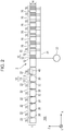
- Fig. 2 illustrates the structure of the holding apparatus 100 and includes a sectional view of the chuck 1 taken along line A-A.
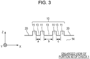
- Fig. 3 is an enlarged view of a region 40 in Fig. 2 .
- the holding apparatus 100 includes the chuck 1, an exhaust portion 30, and a pipe 31.
- the exhaust portion 30 exhausts gas from support portions 10 of the chuck 1, and the chuck 1 attracts and holds the substrate that is disposed thereon.
- Three openings 30 are formed in a surface 2 of the chuck 1 on which the substrate is to be held.
- Support pins (not illustrated) that temporally support the substrate when the substrate is loaded into and unload from the holding apparatus 100 project from a base 14 that has the surface 2 through the openings 30.
- the chuck 1 includes the support portions 10 that extend from the surface 2 and regions 20 that concentrically alternate.
- Each support portion 10 includes four convex portions (contact portions) 11 that can be in contact with the substrate and three concave portions 13.
- the support portion is formed such that the concave portions 13 are located between the corresponding convex portions 11 that are adjacent to each other.
- the four convex portions 11 and the three concave portions 13 are arranged in the direction (one direction) from the center of the chuck 1 toward the outer circumference of the chuck 1, and the three concave portions 13 are lined up in the direction from the center of the chuck 1 toward the outer circumference of the chuck 1 (continuously formed such that no regions 20 are interposed therebetween).
- the widths of the three concave portions 13 can be determined without limitation.
- the width b of the central concave portion 13 is preferably more than the widths a and c of the concave portions 13 (the other concave portions) on both sides. This enables deformation of the substrate in an out-of-plane direction to be restricted at a position away from the concave portions 13 on both sides.
- Each concave portion 13 has at least one opening 12. At least the three concave portions 12 that each support portion 10 includes are connected to the common exhaust portion 30. That is, the openings 12 are common openings for the three concave portions 13. According to the present embodiment, all of the openings 12 are connected to the common exhaust portion 30.
- the exhaust portion 30 exhausts gas in the concave portions 13 via the openings 12 and the pipe 31.
- An example of the exhaust portion 30 is a vacuum pump. This enables the substrate to be attracted and held by the support portions 10 with the convex portions 11 being in contact with the substrate. Since the upper surface of each convex portion 11 comes into contact with the substrate, the upper surface is preferably processed so as to have high flatness.
- Each region 20 is located between the corresponding support portions 10 and has at least one opening 22.
- Gas such as air
- the pressure of each concave portion 13 becomes a negative pressure with respect to a space (a space between a first support portion and a second support portion) of an upper part of the corresponding region 20 that corresponds to a side space between the corresponding support portions 10.
- the openings 22 may be connected to a gas-supplying portion that supplies a predetermined gas, or gas the pressure of which is adjusted may be supplied.
- the holding apparatus 100 that has the above structure holds the substrate that is unload.
- Each support portion 10 has a structure in which the four convex portions 11 and the concave portions 13 that are located between the corresponding convex portions 11 are arranged in one direction, and accordingly, the flatness of the substrate that is held can be improved.
- the substrate can be held with high flatness maintained even when the substrate is thin.
- the chuck 1 is suitable to hold a special substrate that is drilled to such an extent that the thickness of a central portion is equal to about 1 / 10 of the thickness of an outer circumferential portion.
- Fig. 4 is a sectional view of a chuck 95, which differs from the chuck 1 in that support portions 90 that are arranged at a regular interval each include two convex portions 91 and a concave portion 93 therebetween.
- the support portions 90 are concentrically disposed as with the chuck 1 when the chuck 95 is viewed in the direction of +Z.
- Fig. 5A illustrates the result of a simulation of the flatness of the substrate in the case where the chuck 95 in the comparative example is used to hold the substrate.
- Fig. 5B illustrates the result of a simulation of the flatness of the substrate in the case where the chuck 1 is used to hold the substrate.
- the vertical axis in Fig. 5A and Fig. 5B represents the position of the back surface of the substrate that is held by each chuck in the height direction
- the horizontal axis represents the position of the chuck in the radial direction.
- the left end point on the horizontal axis represents the position of the center of the chuck 1.
- the right end point on the horizontal axis represents the position of the outer circumference thereof.
- a suction pressure at the concave portions is 75 kPa, and the thickness of the substrate is 75 ⁇ m.
- the thickness of the substrate is uniform.
- the chuck 1 and the chuck 95 have the same size.
- Each chuck has eight of the support portions 10 or the support portions 90.
- the position of the back surface of the substrate greatly shifts to an higher position than the position of the other portions at a portion inside the support portion 90 that is nearest to the center of the chuck 95 and at a portion outside the support portion 90 that is nearest to the outer circumference of the chuck 95. That is, a central portion of the substrate and an outer circumference portion of the substrate deform more greatly than the other portions.
- the position of the back surface of portions of the substrate between the support portions 90 shifts to a higher position.
- the position of the back surface of portions of the substrate does not shift to a higher position unlike the example.
- the substrate scarcely deforms between the support portions 10.
- the chuck 1 Comparing the case of the chuck 1 with the case of the chuck 95, the chuck 1 can hold the substrate with flatness less than 1 / 10 of flatness in the case of the chuck 95. That is, it is confirmed that the flatness of the substrate that is held can be improved in a manner in which each support portion 10 has the structure in which the four convex portions 11 and the concave portions 13 that are located between the corresponding convex portions 11 are arranged in one direction.
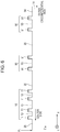
- Fig. 6 is an enlarged view of a section of a chuck 1 according to a second embodiment. Components like to those in the first embodiment are designated by like reference numbers, and a detailed description thereof is omitted.
- the support portion 10 includes three concave portions 13, and the other support portions 90 include the concave portion 93. It is not necessary for all of the support portions that support the substrate to include the three the concave portions 13 as in the support portion 10, provided that at least one of the support portions includes the three concave portions 13. According to the present embodiment, the same effects as in the first embodiment are achieved.
- the support portion that is nearest to the position P0 of the center of the chuck 1 is preferably the support portion 10.
- Fig. 7 illustrates the result of a simulation representing the position of the back surface of a substrate that is held by the chuck 1 according to the second embodiment.
- the conditions of the simulation and the axes are the same as described above except that the structure of the chuck 1 is changed, and a detailed description thereof is omitted.
- the deformation of the central portion of the substrate which notably appears in the comparative example described above, can be greatly inhibited in a manner in which the support portion 10 is merely disposed at the position nearest to the center of the chuck 1.
- the substrate can be held so as to have good flatness.
- the support portion that is nearest to the outer circumference of the chuck 1 may be the support portion 10 instead of the support portion that is nearest to the center of the chuck 1.
- the support portion that is nearest to the center of the chuck 1 and the support portion that is nearest to the outer circumference of the chuck 1 may be the support portions 10. This enables the flatness of the substrate that is held to be improved.
- Fig. 8 illustrates the structure of a holding apparatus 300 according to a third embodiment and includes a sectional view of the chuck 1. Components like to those in the first embodiment are designated by like reference numbers, and a detailed description thereof is omitted.
- the holding apparatus 300 controls an exhaust unit by using a control unit 35 to separately control the suction pressure applied at the support portion 10 (some of the support portions) that is nearest to the position P0 of the center of the chuck 1 and the suction pressure of the substrate applied at the other support portions 10.
- the holding apparatus 300 includes the exhaust portion 30, pipes 31a and 31b, pressure gauges 32a and 32b, solenoid valves 33a and 33b, and adjusters 34a and 34b that serve as the exhaust unit.
- the pressure gauge 32a measures the pressure of the inside of the pipe 31a.
- the pressure gauge 32b measures the pressure of the inside of the pipe 31b.
- the solenoid valve 33a switches between ON and OFF of exhaust of the pipe 31a.
- the solenoid valve 33b switches between ON and OFF of exhaust of the pipe 31b.
- the adjuster 34a adjusts the pressure of the inside of the pipe 31a.
- the adjuster 34b adjusts the pressure of the inside of the pipe 31a.
- the control unit 35 controls the solenoid valves 33a and 33b and the adjusters 34a and 34b.
- control unit 35 controls the adjuster 34b such that a predetermined pressure of the inside of the pipe 31b is maintained, and only the pressure of the inside of the pipe 31a is changed.
- Fig. 9 illustrates the result of a simulation representing the position of the back surface of a substrate that is held by the chuck 1 according to the third embodiment.
- the conditions of the simulation and the axes are the same as described above except that the structure of the chuck 1 is changed, and a detailed description thereof is omitted.
- the control unit 35 controls the pressure of the inside of the pipe 31a on the basis of information about the flatness of the central portion of the substrate.
- a solid line represents the position of the back surface of the substrate in the height direction in the case where the substrate is held with a suction pressure of 75 kPa applied at all of the support portions 10.
- a dashed line represents the position of the back surface of the substrate in the height direction in the case where the suction pressure applied at the support portion 10 that is nearest to the position P0 of the center of the chuck 1 is decreased to 40 kPa.
- a suction force at the first support portion is preferably adjusted to 75 kPa in advance.
- the position of the back surface can be higher than that at the outer circumferential portion in advance, and the flatness of the front surface of the substrate can be improved.
- the holding apparatus 300 also achieves the same effects as in the first embodiment.
- degradation of the flatness due to distribution of the thickness of the substrate can be compensated in a manner in which the pressure of the pipe 31a is controlled to control the position of the back surface of the substrate.
- the control unit 35 may obtain the information about the flatness on the basis of the result of measurement of the thickness with another measuring instrument before loading onto the holding apparatus 300 or may obtain the information about the flatness by measuring the position of the front surface of the substrate with ultrasonic waves or light after loading onto the holding apparatus 300. Alternatively, information inputted from a user may be obtained as the information about the flatness of the substrate.
- the control of the suction pressure by the control unit 35 includes switching between ON and OFF of exhaust by control of the solenoid valves 33a and 33b.
- the suction pressure may be continuously controlled for the pipe 31b.
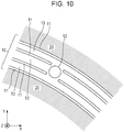
- Fig. 10 is an enlarged view of a chuck 1 according to a fourth embodiment viewed in the direction of +Z and illustrates a portion thereof that includes the support portion 10. Components like to those in the first embodiment are designated by like reference numbers, and a detailed description thereof is omitted. Gas in the three concave portions 13 may be exhausted through the opening 12.
- the chuck 1 can achieve the same effects as in the first embodiment.
- the chuck 1 is suitable for the case where it is difficult to form the openings 12 corresponding to the respective concave portions 13 because the widths a, b, and c of the concave portions 13 are narrow.
- Each support portion 10 may not have the structure in which the four convex portions 11 and the three concave portion 13 are arranged in one direction but may have a structure in which three convex portions 11 and two concave portions 13 are arranged in one direction.
- One or more support portions 10 preferably have the structure in which the three convex portions 11 and the two concave portions 13 are arranged in one direction.
- the chuck 1 includes three or more support portions
- at least one of the support portions other than the support portion that is nearest to the center of the chuck 1 and the support portion that is nearest to the outer circumference of the chuck 1 may be the support portion 10.
- the support portion that is nearest to the center of the chuck 1, the support portion that is nearest to the outer circumference of the chuck 1, and the at least one of the other support portions are more preferably the support portions 10 that have the structure in which the three convex portions 11 and the two concave portions 13 are arranged in one direction.
- the chuck 1 according to the present embodiment can improve the flatness of the substrate that is held more than the case of the chuck 95.
- Fig. 11 illustrates the structure of an exposure device 600 that corresponds to the lithography apparatus.
- An axis parallel to an optical axis (vertical direction according to the present embodiment) of a projection optical system 604 is referred to as the Z-axis.
- Axes perpendicular to each other in a plane perpendicular to the Z-axis are referred to the X-axis and the Y-axis.
- the exposure device 600 illuminates a reticle (original) 602 with illumination light 603 via an illumination optical system 601 to cast an image of a pattern that is formed on the reticle 602 illuminated on a substrate 605 via the projection optical system 604.
- a stage 606 holds the reticle 602 and causes the reticle 602 to be scanned in the direction of the X-axis.
- a stage 607 moves the chuck 1 and the substrate 605 that is held by the chuck 1 by using a driving mechanism (not illustrated) such as a linear motor.
- the exposure device 600 causes the reticle 602 and the substrate 605 to be relatively scanned by using the stages 606 and 607 and forms a latent image pattern on a resist that is applied to the substrate 605.
- An interferometer 608 radiates a laser beam to a mirror 609, and an interferometer 610 radiates a laser beam to a mirror 611. The reflected light thereof is received to detect the position of the reticle 602 and the substrate 605.
- a detector 612 detects an alignment mark (not illustrated) that is formed on the substrate 605 and a reference mark (not illustrated) that is formed on the stage 607.
- the holding apparatus 100 includes a top plate 614 that includes pins 613 for supporting the substrate 605 when the substrate 605 is load and unload, and a lifting mechanism (not illustrated) that lifts and lowers the chuck 1 and the top plate 614 with respect to the pins 613 in addition to the above components.
- a control unit 615 is connected to the stages 606 and 607, the detector 612, the interferometers 608 and 610, and the holding apparatus 100 and comprehensively controls these. For example, during an exposure process, the position at which the pattern is formed is determined on the basis of the detection result of the detector 612, and the stages 606 and 607 are controlled on the basis of information about the position that is obtained from the interferometers 608 and 610.
- the control unit 615 controls movement of the lifting mechanism and the stage 607 of the holding apparatus 100 when the substrate 605 is loaded and unload.
- the control unit 615 may be disposed in a housing that accommodates the other components other than the control unit 615 or may be disposed in another housing that differs from the above housing.
- the holding apparatus 100 enables the flatness of the substrate 605 to be improved unlike the case where a holding apparatus that uses a support portion that does not include the three concave portions 13. Accordingly, exposure is facilitated while the position of the front surface of the substrate 605 is adjusted to the position of focus of exposure light 616. This inhibits degradation of resolution of the pattern that is formed on the substrate 605. The resolution can be degraded when the flatness of the substrate 605 is not good.
- the exposure device 600 may be equipped with the chuck 1 according to any one of the second to fifth embodiments or the holding apparatus 100 or 300.
- Light radiated by the exposure device 600 toward the substrate 605 is not limited to i-line (a wavelength of 365 nm) and may be ultraviolet light such as KrF light (a wavelength of 248 nm) or ArF light (a wave length of 193 nm) or visible light such as g-line (a wave length of 436 nm).
- the lithography apparatus according to the embodiment of the present invention may be an apparatus that forms a pattern of a resist (imprinting material) on a substrate by an imprinting method or an apparatus that prints a latent image pattern on a wafer by radiating a laser beam or a charged particle beam to the substrate.
- each support portion 10 of the chuck 1 is not necessarily a continuous circular shape (annular shape) but may be a continuous rectangular shape (rectangular frame shape).
- Fig. 1 illustrates the support portions 10 that are concentric, that is, the annular support portions 10 are arranged in a multiple arrangement in the direction along the substrate that is held by the chuck 1 but may not be arranged in this way.
- the shapes of the support portions 10 may be obtained from a combination of linear support portions 10 that divide the surface 2 into rectangular regions.
- a combination of the linear support portions 10 and the annular support portions 10 is also acceptable.
- an illustration of the concave portions 13 and the openings 12 that are included in the support portions 10 is omitted.
- the number of the support portions 10 may be plural.
- a continuous support portion 10 may be arranged in a multiple arrangement along the front surface of the substrate that is held by the chuck 1.
- the support portions 10 may be integrally molded with the base 14 that has the surface 2 or may be separated from the base 14.
- the height of the bottom of each concave portion 13 may be the same as the height of the surface 2 or may be higher than the height of the surface 2.
- the third embodiment may be appropriately combined with the chuck 1 according to any one of the other embodiments and carried out.
- the arrangement of the opening 12 described according to the fourth embodiment may be appropriately combined with the chuck 1 according to any one of the other embodiments.
- the pattern that is formed on the substrate by using the lithography apparatus is temporally used when various articles are manufactured.
- the articles include an electrical circuit element, an optical element, MEMS, a print element, a sensor, and a mold.
- the electrical circuit element include non-volatile or volatile semiconductor memories such as a DRAM, a SRAM, a flash memory, and a MRAM, and semiconductor elements such as a LSI chip, a CCD, and an image sensor, and a FPGA.
- the mold include a mold for imprinting.
- the pattern that is formed by using the lithography apparatus is etched or subjected to an ion implantation process during processing of the substrate, and subsequently, a resist used as a mask is removed.
- the resist is developed before processing described above.
- a solidified pattern of the resist that is formed by using an imprinting apparatus as the lithography apparatus may be used as a component of at least part of the above article.
Landscapes
- Physics & Mathematics (AREA)
- General Physics & Mathematics (AREA)
- Container, Conveyance, Adherence, Positioning, Of Wafer (AREA)
- Exposure And Positioning Against Photoresist Photosensitive Materials (AREA)
- Shaping Of Tube Ends By Bending Or Straightening (AREA)
Abstract
Description
- The present invention relates to a chuck, a substrate-holding apparatus, a pattern-forming apparatus, and a method of manufacturing an article.
- In a substrate-holding apparatus with which a lithography apparatus or another apparatus is equipped, good flatness of a substrate needs to be maintained to focus exposure light accurately.
-
PTL 1 discloses that the upper surface of a chuck is divided into rectangular sections by using a support portion that includes two convex portions and a concave portion therebetween.PTL 1 discloses that gas in the concave portion is exhausted to hold a substrate, and the amount of gas that is supplied to and exhausted from the rectangular sections is controlled in accordance with the result of measurement of the flatness of the substrate held, so that the flatness of the substrate is corrected. - PTL 1: Japanese Patent Laid-Open No.
6-196381 - A substrate having a decreased thickness is increasingly used. There is a risk that the flatness of the front surface of the substrate is degraded due to contact between the chuck and the substrate when the substrate is held by exhaust depending on the structure of a portion of the chuck that comes into contact with the back surface of the substrate.
- In view of this, it is an object of the present invention to provide a chuck, a substrate-holding apparatus, and a lithography apparatus that enable the flatness of a substrate that is held to be improved.
- A chuck according to an embodiment of the present invention includes first and second support portions each of which has a repetition structure of a convex portion and a concave portion on a base. A substrate is held by bringing each convex portion into contact with the substrate and exhausting gas in each concave portion such that the concave portion has a negative pressure with respect to a space between the first support portion and the second support portion. At least one support portion of the first support portion and the second support portion includes at least four of the convex portions and three concave portions.
-
-
Fig. 1 illustrates a chuck according to a first embodiment viewed in the direction of +Z. -
Fig. 2 illustrates the structure of a holding apparatus according to the first embodiment. -
Fig. 3 is an enlarged view of a sectional view of the chuck. -
Fig. 4 illustrates the structure of a chuck according to a comparative example. -
Fig. 5A illustrates the result of a simulation in the case where the chuck in the comparative example is used. -
Fig. 5B illustrates the result of a simulation in the case where the chuck according to the first embodiment is used. -
Fig. 6 is an enlarged view of a section of a chuck according to a second embodiment. -
Fig. 7 illustrates the position of the back surface of a substrate that is held by the chuck according to the second embodiment. -
Fig. 8 illustrates the structure of a holding apparatus according to a third embodiment. -
Fig. 9 illustrates the position of the back surface of a substrate that is held by the chuck according to the third embodiment. -
Fig. 10 illustrates a chuck according to a fourth embodiment viewed in the direction of +Z. -
Fig. 11 illustrates the structure of an exposure device. -
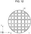
Fig. 12 illustrates another structure of a chuck. - The structure of a
chuck 1 and a holding apparatus (substrate-holding apparatus) 100 that holds a substrate according to a first embodiment will be described with reference toFig. 1 ,Fig. 2 , andFig. 3 . An axis perpendicular to a direction along the front surface of the substrate that is held by thechuck 1 is referred to as a Z-axis, and axes perpendicular to each other in a plane perpendicular to the Z-axis are referred to as an X-axis and a Y-axis.Fig. 1 illustrates thechuck 1 viewed in the direction of +Z.Fig. 2 illustrates the structure of theholding apparatus 100 and includes a sectional view of thechuck 1 taken along line A-A.Fig. 3 is an enlarged view of aregion 40 inFig. 2 . - The
holding apparatus 100 includes thechuck 1, anexhaust portion 30, and apipe 31. Theexhaust portion 30 exhausts gas fromsupport portions 10 of thechuck 1, and thechuck 1 attracts and holds the substrate that is disposed thereon. - Three
openings 30 are formed in a surface 2 of thechuck 1 on which the substrate is to be held. Support pins (not illustrated) that temporally support the substrate when the substrate is loaded into and unload from theholding apparatus 100 project from abase 14 that has the surface 2 through theopenings 30. - The
chuck 1 includes thesupport portions 10 that extend from the surface 2 andregions 20 that concentrically alternate. Eachsupport portion 10 includes four convex portions (contact portions) 11 that can be in contact with the substrate and threeconcave portions 13. The support portion is formed such that theconcave portions 13 are located between the correspondingconvex portions 11 that are adjacent to each other. In thesupport portion 10, the fourconvex portions 11 and the threeconcave portions 13 are arranged in the direction (one direction) from the center of thechuck 1 toward the outer circumference of thechuck 1, and the threeconcave portions 13 are lined up in the direction from the center of thechuck 1 toward the outer circumference of the chuck 1 (continuously formed such that noregions 20 are interposed therebetween). - The widths of the three
concave portions 13 can be determined without limitation. For example, as illustrated inFig. 3 , the width b of the centralconcave portion 13 is preferably more than the widths a and c of the concave portions 13 (the other concave portions) on both sides. This enables deformation of the substrate in an out-of-plane direction to be restricted at a position away from theconcave portions 13 on both sides. - Each
concave portion 13 has at least one opening 12. At least the threeconcave portions 12 that eachsupport portion 10 includes are connected to thecommon exhaust portion 30. That is, theopenings 12 are common openings for the threeconcave portions 13. According to the present embodiment, all of theopenings 12 are connected to thecommon exhaust portion 30. Theexhaust portion 30 exhausts gas in theconcave portions 13 via theopenings 12 and thepipe 31. An example of theexhaust portion 30 is a vacuum pump. This enables the substrate to be attracted and held by thesupport portions 10 with theconvex portions 11 being in contact with the substrate. Since the upper surface of eachconvex portion 11 comes into contact with the substrate, the upper surface is preferably processed so as to have high flatness. - Each
region 20 is located between thecorresponding support portions 10 and has at least one opening 22. Gas (such as air) in the atmosphere in which thechuck 1 is disposed can enter and exit theopenings 22. In this way, the pressure of eachconcave portion 13 becomes a negative pressure with respect to a space (a space between a first support portion and a second support portion) of an upper part of thecorresponding region 20 that corresponds to a side space between thecorresponding support portions 10. - When the pressure of each
concave portion 13 is a negative pressure with respect to the side space between thesupport portions 10, theopenings 22 may be connected to a gas-supplying portion that supplies a predetermined gas, or gas the pressure of which is adjusted may be supplied. - This prevents portions of the substrate that face the
regions 20 from coming into contact with theregions 20 even when the exhaust portion 30 exhausts gas in theconcave portions 13. Consequently, the flatness of the substrate is improved, and particles that attach to the substrate can be decreased unlike the case where gas in the spaces of the upper parts of theregions 20 is exhausted. In addition, a suction mark, which can be left when thechuck 1 sucks the substrate too strongly, is not formed on the substrate. - The
holding apparatus 100 that has the above structure holds the substrate that is unload. Eachsupport portion 10 has a structure in which the fourconvex portions 11 and theconcave portions 13 that are located between the correspondingconvex portions 11 are arranged in one direction, and accordingly, the flatness of the substrate that is held can be improved. In particular, the substrate can be held with high flatness maintained even when the substrate is thin. For example, thechuck 1 is suitable to hold a special substrate that is drilled to such an extent that the thickness of a central portion is equal to about 1 / 10 of the thickness of an outer circumferential portion. - An example when the
chuck 1 holds a substrate will be described with a comparative example. -
Fig. 4 is a sectional view of achuck 95, which differs from thechuck 1 in thatsupport portions 90 that are arranged at a regular interval each include twoconvex portions 91 and aconcave portion 93 therebetween. Thesupport portions 90 are concentrically disposed as with thechuck 1 when thechuck 95 is viewed in the direction of +Z. -
Fig. 5A illustrates the result of a simulation of the flatness of the substrate in the case where thechuck 95 in the comparative example is used to hold the substrate.Fig. 5B illustrates the result of a simulation of the flatness of the substrate in the case where thechuck 1 is used to hold the substrate. The vertical axis inFig. 5A and Fig. 5B represents the position of the back surface of the substrate that is held by each chuck in the height direction, and the horizontal axis represents the position of the chuck in the radial direction. The left end point on the horizontal axis represents the position of the center of thechuck 1. The right end point on the horizontal axis represents the position of the outer circumference thereof. - In the simulations, a suction pressure at the concave portions is 75 kPa, and the thickness of the substrate is 75 µm. The thickness of the substrate is uniform. The
chuck 1 and thechuck 95 have the same size. Each chuck has eight of thesupport portions 10 or thesupport portions 90. - In the case where the
chuck 95 is used to attract and hold the substrate, the position of the back surface of the substrate greatly shifts to an higher position than the position of the other portions at a portion inside thesupport portion 90 that is nearest to the center of thechuck 95 and at a portion outside thesupport portion 90 that is nearest to the outer circumference of thechuck 95. That is, a central portion of the substrate and an outer circumference portion of the substrate deform more greatly than the other portions. In addition, the position of the back surface of portions of the substrate between thesupport portions 90 shifts to a higher position. - In the case where the
chuck 1 is used to hold the substrate, the position of the back surface of portions of the substrate does not shift to a higher position unlike the example. In addition, the substrate scarcely deforms between thesupport portions 10. - Comparing the case of the
chuck 1 with the case of thechuck 95, thechuck 1 can hold the substrate with flatness less than 1 / 10 of flatness in the case of thechuck 95. That is, it is confirmed that the flatness of the substrate that is held can be improved in a manner in which eachsupport portion 10 has the structure in which the fourconvex portions 11 and theconcave portions 13 that are located between the correspondingconvex portions 11 are arranged in one direction. -
Fig. 6 is an enlarged view of a section of achuck 1 according to a second embodiment. Components like to those in the first embodiment are designated by like reference numbers, and a detailed description thereof is omitted. - In the
chuck 1 according to the present embodiment, thesupport portion 10 includes threeconcave portions 13, and theother support portions 90 include theconcave portion 93. It is not necessary for all of the support portions that support the substrate to include the three theconcave portions 13 as in thesupport portion 10, provided that at least one of the support portions includes the threeconcave portions 13. According to the present embodiment, the same effects as in the first embodiment are achieved. - In particular, as illustrated in
Fig. 6 , the support portion that is nearest to the position P0 of the center of thechuck 1 is preferably thesupport portion 10. -
Fig. 7 illustrates the result of a simulation representing the position of the back surface of a substrate that is held by thechuck 1 according to the second embodiment. The conditions of the simulation and the axes are the same as described above except that the structure of thechuck 1 is changed, and a detailed description thereof is omitted. - The deformation of the central portion of the substrate, which notably appears in the comparative example described above, can be greatly inhibited in a manner in which the
support portion 10 is merely disposed at the position nearest to the center of thechuck 1. The substrate can be held so as to have good flatness. - Alternatively, the support portion that is nearest to the outer circumference of the
chuck 1 may be thesupport portion 10 instead of the support portion that is nearest to the center of thechuck 1. Alternatively, the support portion that is nearest to the center of thechuck 1 and the support portion that is nearest to the outer circumference of thechuck 1 may be thesupport portions 10. This enables the flatness of the substrate that is held to be improved. -
Fig. 8 illustrates the structure of a holdingapparatus 300 according to a third embodiment and includes a sectional view of thechuck 1. Components like to those in the first embodiment are designated by like reference numbers, and a detailed description thereof is omitted. The holdingapparatus 300 controls an exhaust unit by using acontrol unit 35 to separately control the suction pressure applied at the support portion 10 (some of the support portions) that is nearest to the position P0 of the center of thechuck 1 and the suction pressure of the substrate applied at theother support portions 10. - The holding
apparatus 300 includes theexhaust portion 30,pipes pressure gauges solenoid valves adjusters - The
pressure gauge 32a measures the pressure of the inside of thepipe 31a. Thepressure gauge 32b measures the pressure of the inside of thepipe 31b. Thesolenoid valve 33a switches between ON and OFF of exhaust of thepipe 31a. Thesolenoid valve 33b switches between ON and OFF of exhaust of thepipe 31b. Theadjuster 34a adjusts the pressure of the inside of thepipe 31a. Theadjuster 34b adjusts the pressure of the inside of thepipe 31a. Thecontrol unit 35 controls thesolenoid valves adjusters - For simplicity of description, in the case described below, the
control unit 35 controls theadjuster 34b such that a predetermined pressure of the inside of thepipe 31b is maintained, and only the pressure of the inside of thepipe 31a is changed. -
Fig. 9 illustrates the result of a simulation representing the position of the back surface of a substrate that is held by thechuck 1 according to the third embodiment. The conditions of the simulation and the axes are the same as described above except that the structure of thechuck 1 is changed, and a detailed description thereof is omitted. - The
control unit 35 controls the pressure of the inside of thepipe 31a on the basis of information about the flatness of the central portion of the substrate. A solid line represents the position of the back surface of the substrate in the height direction in the case where the substrate is held with a suction pressure of 75 kPa applied at all of thesupport portions 10. A dashed line represents the position of the back surface of the substrate in the height direction in the case where the suction pressure applied at thesupport portion 10 that is nearest to the position P0 of the center of thechuck 1 is decreased to 40 kPa. - As illustrated in
Fig. 9 , it is made clear that a change in the suction pressure enables the position of the back surface of the central portion of the substrate to be changed. - For example, in the case where the central portion of the substrate that is held has a thickness less than that of the outer circumferential portion and the position of the front surface thereof in the height direction is likely to shift to a lower position, a suction force at the first support portion is preferably adjusted to 75 kPa in advance. The position of the back surface can be higher than that at the outer circumferential portion in advance, and the flatness of the front surface of the substrate can be improved.
- The holding
apparatus 300 also achieves the same effects as in the first embodiment. In addition, degradation of the flatness due to distribution of the thickness of the substrate can be compensated in a manner in which the pressure of thepipe 31a is controlled to control the position of the back surface of the substrate. - The
control unit 35 may obtain the information about the flatness on the basis of the result of measurement of the thickness with another measuring instrument before loading onto the holdingapparatus 300 or may obtain the information about the flatness by measuring the position of the front surface of the substrate with ultrasonic waves or light after loading onto the holdingapparatus 300. Alternatively, information inputted from a user may be obtained as the information about the flatness of the substrate. - The control of the suction pressure by the
control unit 35 includes switching between ON and OFF of exhaust by control of thesolenoid valves pipe 31b. -
Fig. 10 is an enlarged view of achuck 1 according to a fourth embodiment viewed in the direction of +Z and illustrates a portion thereof that includes thesupport portion 10. Components like to those in the first embodiment are designated by like reference numbers, and a detailed description thereof is omitted. Gas in the threeconcave portions 13 may be exhausted through theopening 12. - The
chuck 1 can achieve the same effects as in the first embodiment. Thechuck 1 is suitable for the case where it is difficult to form theopenings 12 corresponding to the respectiveconcave portions 13 because the widths a, b, and c of theconcave portions 13 are narrow. - Each
support portion 10 may not have the structure in which the fourconvex portions 11 and the threeconcave portion 13 are arranged in one direction but may have a structure in which threeconvex portions 11 and twoconcave portions 13 are arranged in one direction. - One or
more support portions 10 preferably have the structure in which the threeconvex portions 11 and the twoconcave portions 13 are arranged in one direction. In the case where thechuck 1 includes three or more support portions, at least one of the support portions other than the support portion that is nearest to the center of thechuck 1 and the support portion that is nearest to the outer circumference of thechuck 1 may be thesupport portion 10. The support portion that is nearest to the center of thechuck 1, the support portion that is nearest to the outer circumference of thechuck 1, and the at least one of the other support portions are more preferably thesupport portions 10 that have the structure in which the threeconvex portions 11 and the twoconcave portions 13 are arranged in one direction. - The
chuck 1 according to the present embodiment can improve the flatness of the substrate that is held more than the case of thechuck 95. - An embodiment of a lithography apparatus (pattern-forming apparatus) that is equipped with the holding
apparatus 100 according to the first embodiment will be described.Fig. 11 illustrates the structure of anexposure device 600 that corresponds to the lithography apparatus. An axis parallel to an optical axis (vertical direction according to the present embodiment) of a projectionoptical system 604 is referred to as the Z-axis. Axes perpendicular to each other in a plane perpendicular to the Z-axis are referred to the X-axis and the Y-axis. - The
exposure device 600 illuminates a reticle (original) 602 withillumination light 603 via an illuminationoptical system 601 to cast an image of a pattern that is formed on thereticle 602 illuminated on asubstrate 605 via the projectionoptical system 604. Astage 606 holds thereticle 602 and causes thereticle 602 to be scanned in the direction of the X-axis. Astage 607 moves thechuck 1 and thesubstrate 605 that is held by thechuck 1 by using a driving mechanism (not illustrated) such as a linear motor. - The
exposure device 600 causes thereticle 602 and thesubstrate 605 to be relatively scanned by using thestages substrate 605. Aninterferometer 608 radiates a laser beam to amirror 609, and aninterferometer 610 radiates a laser beam to amirror 611. The reflected light thereof is received to detect the position of thereticle 602 and thesubstrate 605. Adetector 612 detects an alignment mark (not illustrated) that is formed on thesubstrate 605 and a reference mark (not illustrated) that is formed on thestage 607. - The holding
apparatus 100 includes atop plate 614 that includespins 613 for supporting thesubstrate 605 when thesubstrate 605 is load and unload, and a lifting mechanism (not illustrated) that lifts and lowers thechuck 1 and thetop plate 614 with respect to thepins 613 in addition to the above components. - A
control unit 615 is connected to thestages detector 612, theinterferometers apparatus 100 and comprehensively controls these. For example, during an exposure process, the position at which the pattern is formed is determined on the basis of the detection result of thedetector 612, and thestages interferometers control unit 615 controls movement of the lifting mechanism and thestage 607 of the holdingapparatus 100 when thesubstrate 605 is loaded and unload. Thecontrol unit 615 may be disposed in a housing that accommodates the other components other than thecontrol unit 615 or may be disposed in another housing that differs from the above housing. - The holding
apparatus 100 enables the flatness of thesubstrate 605 to be improved unlike the case where a holding apparatus that uses a support portion that does not include the threeconcave portions 13. Accordingly, exposure is facilitated while the position of the front surface of thesubstrate 605 is adjusted to the position of focus of exposure light 616. This inhibits degradation of resolution of the pattern that is formed on thesubstrate 605. The resolution can be degraded when the flatness of thesubstrate 605 is not good. - The
exposure device 600 may be equipped with thechuck 1 according to any one of the second to fifth embodiments or the holdingapparatus - Light radiated by the
exposure device 600 toward thesubstrate 605 is not limited to i-line (a wavelength of 365 nm) and may be ultraviolet light such as KrF light (a wavelength of 248 nm) or ArF light (a wave length of 193 nm) or visible light such as g-line (a wave length of 436 nm). The lithography apparatus according to the embodiment of the present invention may be an apparatus that forms a pattern of a resist (imprinting material) on a substrate by an imprinting method or an apparatus that prints a latent image pattern on a wafer by radiating a laser beam or a charged particle beam to the substrate. - The shape of each
support portion 10 of thechuck 1 is not necessarily a continuous circular shape (annular shape) but may be a continuous rectangular shape (rectangular frame shape).Fig. 1 illustrates thesupport portions 10 that are concentric, that is, theannular support portions 10 are arranged in a multiple arrangement in the direction along the substrate that is held by thechuck 1 but may not be arranged in this way. - As illustrated in
Fig. 12 , the shapes of thesupport portions 10 may be obtained from a combination oflinear support portions 10 that divide the surface 2 into rectangular regions. A combination of thelinear support portions 10 and theannular support portions 10 is also acceptable. InFig. 12 , an illustration of theconcave portions 13 and theopenings 12 that are included in thesupport portions 10 is omitted. - As described according to the embodiments, the number of the
support portions 10 may be plural. Acontinuous support portion 10 may be arranged in a multiple arrangement along the front surface of the substrate that is held by thechuck 1. - The
support portions 10 may be integrally molded with the base 14 that has the surface 2 or may be separated from thebase 14. The height of the bottom of eachconcave portion 13 may be the same as the height of the surface 2 or may be higher than the height of the surface 2. - The third embodiment may be appropriately combined with the
chuck 1 according to any one of the other embodiments and carried out. The arrangement of theopening 12 described according to the fourth embodiment may be appropriately combined with thechuck 1 according to any one of the other embodiments. - The pattern that is formed on the substrate by using the lithography apparatus (pattern-forming apparatus) is temporally used when various articles are manufactured. Examples of the articles include an electrical circuit element, an optical element, MEMS, a print element, a sensor, and a mold. Examples of the electrical circuit element include non-volatile or volatile semiconductor memories such as a DRAM, a SRAM, a flash memory, and a MRAM, and semiconductor elements such as a LSI chip, a CCD, and an image sensor, and a FPGA. Examples of the mold include a mold for imprinting.
- The pattern that is formed by using the lithography apparatus is etched or subjected to an ion implantation process during processing of the substrate, and subsequently, a resist used as a mask is removed. In the case where the exposure device or a drawing apparatus is used as the lithography apparatus, the resist is developed before processing described above. A solidified pattern of the resist that is formed by using an imprinting apparatus as the lithography apparatus may be used as a component of at least part of the above article.
- Preferred embodiments of the present invention are described above. It goes without saying that the present invention is not limited to the embodiments. Various modifications and alterations can be made within the range of the spirit thereof.
- This application claims the benefit of Japanese Patent Application No.
2016-109651, filed June 1, 2016
Claims (12)
- A chuck comprising:first and second support portions each of which has a repetition structure of a convex portion and a concave portion on a base,wherein a substrate is held by bringing each convex portion into contact with the substrate and exhausting gas in each concave portion such that the concave portion has a negative pressure with respect to a space between the first support portion and the second support portion, andwherein at least one support portion of the first support portion and the second support portion includes at least four of the convex portions and three concave portions.
- The chuck according to Claim 1, wherein the four convex portions and the three concave portions are arranged in a direction from a center of the chuck toward an outer circumference of the chuck.
- The chuck according to Claim 1, wherein a width of a central concave portion of the three concave portions in the direction is more than widths of the other two concave portions of the three concave portions.
- The chuck according to Claim 1, further comprising: a plurality of support portions each of which has the repetition structure on the base, wherein the at least one support portion is located nearer than the plurality of support portions to a center of the chuck.
- The chuck according to Claim 1, wherein the first and second support portions have an annular shape and are arranged on the base in a multiple arrangement.
- The chuck according to Claim 1, wherein an opening for exhausting the gas in the three concave portions is a common opening.
- The chuck according to Claim 1, wherein the base and the first and second support portions are integrally molded.
- A substrate-holding apparatus that holds a substrate, comprising:the chuck according to any one of Claims 1 to 7; andan exhaust portion that exhausts the gas in each concave portion of the chuck to hold the substrate.
- The substrate-holding apparatus according to Claim 8, wherein the exhaust portion adjusts pressures of the concave portion of the first support portion and the concave portion of the second support portion to different pressures on a basis of information about flatness of the substrate.
- The substrate-holding apparatus according to Claim 8, wherein the information is about distribution of a thickness of the substrate.
- A pattern-forming apparatus that forms a pattern on a substrate with an original, comprising:the chuck according to any one of Claims 1 to 7; andan exhaust portion that exhausts the gas in each concave portion of the chuck to hold the substrate.
- A method of manufacturing an article, comprising:a step of forming a pattern on a substrate with the pattern-forming apparatus according to Claim 11; anda step of processing the substrate on which the pattern is formed to manufacture the article.
Applications Claiming Priority (2)
| Application Number | Priority Date | Filing Date | Title |
|---|---|---|---|
| JP2016109651A JP6758920B2 (en) | 2016-06-01 | 2016-06-01 | Manufacturing method of chuck, substrate holding device, pattern forming device, and article |
| PCT/JP2017/019917 WO2017209051A1 (en) | 2016-06-01 | 2017-05-29 | Chuck, substrate holding device, pattern forming device, and method for manufacturing article |
Publications (3)
| Publication Number | Publication Date |
|---|---|
| EP3467870A1 true EP3467870A1 (en) | 2019-04-10 |
| EP3467870A4 EP3467870A4 (en) | 2020-02-26 |
| EP3467870B1 EP3467870B1 (en) | 2022-07-27 |
Family
ID=60477425
Family Applications (1)
| Application Number | Title | Priority Date | Filing Date |
|---|---|---|---|
| EP17806606.4A Active EP3467870B1 (en) | 2016-06-01 | 2017-05-29 | Chuck, substrate holding device, pattern forming device, and method for manufacturing article |
Country Status (8)
| Country | Link |
|---|---|
| US (1) | US10754262B2 (en) |
| EP (1) | EP3467870B1 (en) |
| JP (1) | JP6758920B2 (en) |
| KR (1) | KR102169894B1 (en) |
| CN (1) | CN109314077B (en) |
| SG (1) | SG11201810641UA (en) |
| TW (1) | TWI648815B (en) |
| WO (1) | WO2017209051A1 (en) |
Families Citing this family (6)
| Publication number | Priority date | Publication date | Assignee | Title |
|---|---|---|---|---|
| CN107604309B (en) * | 2017-11-06 | 2023-09-15 | 京东方科技集团股份有限公司 | Mask laminating device and its laminating method |
| KR102628919B1 (en) * | 2019-05-29 | 2024-01-24 | 주식회사 원익아이피에스 | Substrate processing apparatus and method using the same |
| US11776840B2 (en) * | 2019-10-29 | 2023-10-03 | Canon Kabushiki Kaisha | Superstrate chuck, method of use, and method of manufacturing an article |
| US11728204B2 (en) | 2020-10-23 | 2023-08-15 | Kla Corporation | High flow vacuum chuck |
| US11794314B2 (en) * | 2021-08-30 | 2023-10-24 | Kla Corporation | Quick swap chuck with vacuum holding interchangeable top plate |
| KR102413824B1 (en) * | 2022-01-04 | 2022-06-28 | 주식회사 메이코리아 | Fixing jig for rotatably fixing workpiece using vacuum pressure |
Family Cites Families (28)
| Publication number | Priority date | Publication date | Assignee | Title |
|---|---|---|---|---|
| JPH045646U (en) * | 1990-04-27 | 1992-01-20 | ||
| DE69133413D1 (en) * | 1990-05-07 | 2004-10-21 | Canon Kk | Vacuum type substrate support |
| JPH0521584A (en) * | 1991-07-16 | 1993-01-29 | Nikon Corp | Holding device |
| JPH05235151A (en) * | 1992-02-20 | 1993-09-10 | Canon Inc | Substrate holding board |
| JPH0851143A (en) * | 1992-07-20 | 1996-02-20 | Nikon Corp | Substrate holding device |
| JPH06196381A (en) | 1992-12-22 | 1994-07-15 | Canon Inc | Substrate holding device |
| JPH0831719A (en) * | 1994-07-13 | 1996-02-02 | Nikon Corp | Suction holder for semiconductor substrate and projection exposure apparatus |
| JP3487368B2 (en) * | 1994-09-30 | 2004-01-19 | 株式会社ニコン | Scanning exposure equipment |
| US5923408A (en) * | 1996-01-31 | 1999-07-13 | Canon Kabushiki Kaisha | Substrate holding system and exposure apparatus using the same |
| JP2821678B2 (en) * | 1997-04-07 | 1998-11-05 | 株式会社ニコン | Substrate suction device |
| JP2000100895A (en) * | 1998-09-18 | 2000-04-07 | Nikon Corp | Substrate transfer device, substrate holding device, and substrate processing device |
| EP1291910B1 (en) * | 2000-01-28 | 2007-01-10 | Hitachi Tokyo Electronics Co., Ltd. | Wafer chuck, exposure system, and method of manufacturing semiconductor device |
| JP3859937B2 (en) * | 2000-06-02 | 2006-12-20 | 住友大阪セメント株式会社 | Electrostatic chuck |
| EP1458019A3 (en) * | 2003-03-13 | 2005-12-28 | VenTec Gesellschaft für Venturekapital und Unternehmensberatung | Mobile transportable electrostatic substrate holders |
| EP1491953A1 (en) * | 2003-06-23 | 2004-12-29 | ASML Netherlands B.V. | Lithographic apparatus, device manufacturing method, and device manufactured thereby |
| JP4229380B2 (en) * | 2003-09-30 | 2009-02-25 | コバレントマテリアル株式会社 | Vacuum chuck for substrate holding |
| DE602004030481D1 (en) * | 2003-12-15 | 2011-01-20 | Nippon Kogaku Kk | STAGE SYSTEM, EXPOSURE DEVICE AND EXPOSURE METHOD |
| SG186621A1 (en) * | 2004-06-09 | 2013-01-30 | Nikon Corp | Substrate holding device, exposure apparatus having same, exposure method, method for producing device, and liquid repellent plate |
| US8102512B2 (en) * | 2004-09-17 | 2012-01-24 | Nikon Corporation | Substrate holding device, exposure apparatus, and device manufacturing method |
| KR100689843B1 (en) * | 2006-01-03 | 2007-03-08 | 삼성전자주식회사 | Wafer stage and wafer mounting method using same |
| JPWO2007083592A1 (en) * | 2006-01-17 | 2009-06-11 | 株式会社ニコン | Substrate holding apparatus, exposure apparatus, and device manufacturing method |
| US7791708B2 (en) * | 2006-12-27 | 2010-09-07 | Asml Netherlands B.V. | Lithographic apparatus, substrate table, and method for enhancing substrate release properties |
| US9013682B2 (en) * | 2007-06-21 | 2015-04-21 | Asml Netherlands B.V. | Clamping device and object loading method |
| US8540819B2 (en) * | 2008-03-21 | 2013-09-24 | Ngk Insulators, Ltd. | Ceramic heater |
| US8336188B2 (en) * | 2008-07-17 | 2012-12-25 | Formfactor, Inc. | Thin wafer chuck |
| KR20140124948A (en) * | 2013-04-16 | 2014-10-28 | 주식회사 월덱스 | Flatness, ease of maintenance and to prevent chipping vacuum chuck for semiconductor manufacturing equipment |
| JP6340693B2 (en) * | 2013-07-18 | 2018-06-13 | 株式会社ブイ・テクノロジー | Substrate holding device, contact exposure device, and proximity exposure device |
| JP6706182B2 (en) * | 2016-09-16 | 2020-06-03 | キオクシア株式会社 | Substrate holding device |
-
2016
- 2016-06-01 JP JP2016109651A patent/JP6758920B2/en active Active
-
2017
- 2017-05-29 WO PCT/JP2017/019917 patent/WO2017209051A1/en not_active Ceased
- 2017-05-29 KR KR1020187038187A patent/KR102169894B1/en active Active
- 2017-05-29 CN CN201780033601.4A patent/CN109314077B/en active Active
- 2017-05-29 SG SG11201810641UA patent/SG11201810641UA/en unknown
- 2017-05-29 EP EP17806606.4A patent/EP3467870B1/en active Active
- 2017-06-01 TW TW106118127A patent/TWI648815B/en active
-
2018
- 2018-11-29 US US16/204,563 patent/US10754262B2/en active Active
Also Published As
| Publication number | Publication date |
|---|---|
| SG11201810641UA (en) | 2018-12-28 |
| KR102169894B1 (en) | 2020-10-26 |
| US20190094700A1 (en) | 2019-03-28 |
| EP3467870B1 (en) | 2022-07-27 |
| TW201743405A (en) | 2017-12-16 |
| TWI648815B (en) | 2019-01-21 |
| CN109314077A (en) | 2019-02-05 |
| EP3467870A4 (en) | 2020-02-26 |
| JP2017216375A (en) | 2017-12-07 |
| KR20190015414A (en) | 2019-02-13 |
| WO2017209051A1 (en) | 2017-12-07 |
| JP6758920B2 (en) | 2020-09-23 |
| CN109314077B (en) | 2023-06-02 |
| US10754262B2 (en) | 2020-08-25 |
Similar Documents
| Publication | Publication Date | Title |
|---|---|---|
| US10754262B2 (en) | Chuck, substrate-holding apparatus, pattern-forming apparatus, and method of manufacturing article | |
| JP7068378B2 (en) | Board holder, lithography equipment and device manufacturing method | |
| JP2019144599A (en) | Substrate supporter, method for mounting substrate on substrate supporter location, lithography device, and device manufacturing method | |
| JP2017175071A (en) | Holding apparatus, holding method, lithographic apparatus, and article manufacturing method | |
| US9939736B2 (en) | Substrate holder and support table for lithography | |
| JP6609694B2 (en) | Substrate holder, lithographic apparatus, and device manufacturing method | |
| JP6420900B2 (en) | Lithographic apparatus support table, substrate loading method, lithographic apparatus and device manufacturing method | |
| KR102870947B1 (en) | Chuck, substrate holding apparatus, substrate processing apparatus, and article manufacturing method | |
| CN109416513B (en) | Stage system, lithographic apparatus, method for positioning, and device fabrication method | |
| JP5134705B2 (en) | Apparatus and method for non-contact handling of objects | |
| TWI463274B (en) | Microlithography device and substrate disposal method | |
| US20230182356A1 (en) | Imprint apparatus and article manufacturing method | |
| JP7581146B2 (en) | Chuck, substrate holding device, substrate processing device, and method for manufacturing article | |
| JP6792342B2 (en) | Lithography equipment and its control method, and manufacturing method of articles | |
| JP2017175070A (en) | Holding apparatus, holding method, lithographic apparatus, and article manufacturing method |
Legal Events
| Date | Code | Title | Description |
|---|---|---|---|
| STAA | Information on the status of an ep patent application or granted ep patent |
Free format text: STATUS: THE INTERNATIONAL PUBLICATION HAS BEEN MADE |
|
| PUAI | Public reference made under article 153(3) epc to a published international application that has entered the european phase |
Free format text: ORIGINAL CODE: 0009012 |
|
| STAA | Information on the status of an ep patent application or granted ep patent |
Free format text: STATUS: REQUEST FOR EXAMINATION WAS MADE |
|
| 17P | Request for examination filed |
Effective date: 20190102 |
|
| AK | Designated contracting states |
Kind code of ref document: A1 Designated state(s): AL AT BE BG CH CY CZ DE DK EE ES FI FR GB GR HR HU IE IS IT LI LT LU LV MC MK MT NL NO PL PT RO RS SE SI SK SM TR |
|
| AX | Request for extension of the european patent |
Extension state: BA ME |
|
| DAV | Request for validation of the european patent (deleted) | ||
| DAX | Request for extension of the european patent (deleted) | ||
| A4 | Supplementary search report drawn up and despatched |
Effective date: 20200129 |
|
| RIC1 | Information provided on ipc code assigned before grant |
Ipc: H01L 21/687 20060101ALI20200123BHEP Ipc: G03F 7/20 20060101ALI20200123BHEP Ipc: H01L 21/683 20060101AFI20200123BHEP |
|
| GRAP | Despatch of communication of intention to grant a patent |
Free format text: ORIGINAL CODE: EPIDOSNIGR1 |
|
| STAA | Information on the status of an ep patent application or granted ep patent |
Free format text: STATUS: GRANT OF PATENT IS INTENDED |
|
| INTG | Intention to grant announced |
Effective date: 20220316 |
|
| GRAS | Grant fee paid |
Free format text: ORIGINAL CODE: EPIDOSNIGR3 |
|
| GRAA | (expected) grant |
Free format text: ORIGINAL CODE: 0009210 |
|
| STAA | Information on the status of an ep patent application or granted ep patent |
Free format text: STATUS: THE PATENT HAS BEEN GRANTED |
|
| AK | Designated contracting states |
Kind code of ref document: B1 Designated state(s): AL AT BE BG CH CY CZ DE DK EE ES FI FR GB GR HR HU IE IS IT LI LT LU LV MC MK MT NL NO PL PT RO RS SE SI SK SM TR |
|
| REG | Reference to a national code |
Ref country code: CH Ref legal event code: EP |
|
| REG | Reference to a national code |
Ref country code: DE Ref legal event code: R096 Ref document number: 602017059950 Country of ref document: DE |
|
| REG | Reference to a national code |
Ref country code: AT Ref legal event code: REF Ref document number: 1507640 Country of ref document: AT Kind code of ref document: T Effective date: 20220815 |
|
| REG | Reference to a national code |
Ref country code: IE Ref legal event code: FG4D |
|
| REG | Reference to a national code |
Ref country code: LT Ref legal event code: MG9D |
|
| REG | Reference to a national code |
Ref country code: NL Ref legal event code: MP Effective date: 20220727 |
|
| PG25 | Lapsed in a contracting state [announced via postgrant information from national office to epo] |
Ref country code: SE Free format text: LAPSE BECAUSE OF FAILURE TO SUBMIT A TRANSLATION OF THE DESCRIPTION OR TO PAY THE FEE WITHIN THE PRESCRIBED TIME-LIMIT Effective date: 20220727 Ref country code: RS Free format text: LAPSE BECAUSE OF FAILURE TO SUBMIT A TRANSLATION OF THE DESCRIPTION OR TO PAY THE FEE WITHIN THE PRESCRIBED TIME-LIMIT Effective date: 20220727 Ref country code: PT Free format text: LAPSE BECAUSE OF FAILURE TO SUBMIT A TRANSLATION OF THE DESCRIPTION OR TO PAY THE FEE WITHIN THE PRESCRIBED TIME-LIMIT Effective date: 20221128 Ref country code: NO Free format text: LAPSE BECAUSE OF FAILURE TO SUBMIT A TRANSLATION OF THE DESCRIPTION OR TO PAY THE FEE WITHIN THE PRESCRIBED TIME-LIMIT Effective date: 20221027 Ref country code: NL Free format text: LAPSE BECAUSE OF FAILURE TO SUBMIT A TRANSLATION OF THE DESCRIPTION OR TO PAY THE FEE WITHIN THE PRESCRIBED TIME-LIMIT Effective date: 20220727 Ref country code: LV Free format text: LAPSE BECAUSE OF FAILURE TO SUBMIT A TRANSLATION OF THE DESCRIPTION OR TO PAY THE FEE WITHIN THE PRESCRIBED TIME-LIMIT Effective date: 20220727 Ref country code: LT Free format text: LAPSE BECAUSE OF FAILURE TO SUBMIT A TRANSLATION OF THE DESCRIPTION OR TO PAY THE FEE WITHIN THE PRESCRIBED TIME-LIMIT Effective date: 20220727 Ref country code: FI Free format text: LAPSE BECAUSE OF FAILURE TO SUBMIT A TRANSLATION OF THE DESCRIPTION OR TO PAY THE FEE WITHIN THE PRESCRIBED TIME-LIMIT Effective date: 20220727 Ref country code: ES Free format text: LAPSE BECAUSE OF FAILURE TO SUBMIT A TRANSLATION OF THE DESCRIPTION OR TO PAY THE FEE WITHIN THE PRESCRIBED TIME-LIMIT Effective date: 20220727 |
|
| REG | Reference to a national code |
Ref country code: AT Ref legal event code: MK05 Ref document number: 1507640 Country of ref document: AT Kind code of ref document: T Effective date: 20220727 |
|
| PG25 | Lapsed in a contracting state [announced via postgrant information from national office to epo] |
Ref country code: PL Free format text: LAPSE BECAUSE OF FAILURE TO SUBMIT A TRANSLATION OF THE DESCRIPTION OR TO PAY THE FEE WITHIN THE PRESCRIBED TIME-LIMIT Effective date: 20220727 Ref country code: IS Free format text: LAPSE BECAUSE OF FAILURE TO SUBMIT A TRANSLATION OF THE DESCRIPTION OR TO PAY THE FEE WITHIN THE PRESCRIBED TIME-LIMIT Effective date: 20221127 Ref country code: HR Free format text: LAPSE BECAUSE OF FAILURE TO SUBMIT A TRANSLATION OF THE DESCRIPTION OR TO PAY THE FEE WITHIN THE PRESCRIBED TIME-LIMIT Effective date: 20220727 Ref country code: GR Free format text: LAPSE BECAUSE OF FAILURE TO SUBMIT A TRANSLATION OF THE DESCRIPTION OR TO PAY THE FEE WITHIN THE PRESCRIBED TIME-LIMIT Effective date: 20221028 |
|
| PG25 | Lapsed in a contracting state [announced via postgrant information from national office to epo] |
Ref country code: SM Free format text: LAPSE BECAUSE OF FAILURE TO SUBMIT A TRANSLATION OF THE DESCRIPTION OR TO PAY THE FEE WITHIN THE PRESCRIBED TIME-LIMIT Effective date: 20220727 Ref country code: RO Free format text: LAPSE BECAUSE OF FAILURE TO SUBMIT A TRANSLATION OF THE DESCRIPTION OR TO PAY THE FEE WITHIN THE PRESCRIBED TIME-LIMIT Effective date: 20220727 Ref country code: DK Free format text: LAPSE BECAUSE OF FAILURE TO SUBMIT A TRANSLATION OF THE DESCRIPTION OR TO PAY THE FEE WITHIN THE PRESCRIBED TIME-LIMIT Effective date: 20220727 Ref country code: CZ Free format text: LAPSE BECAUSE OF FAILURE TO SUBMIT A TRANSLATION OF THE DESCRIPTION OR TO PAY THE FEE WITHIN THE PRESCRIBED TIME-LIMIT Effective date: 20220727 Ref country code: AT Free format text: LAPSE BECAUSE OF FAILURE TO SUBMIT A TRANSLATION OF THE DESCRIPTION OR TO PAY THE FEE WITHIN THE PRESCRIBED TIME-LIMIT Effective date: 20220727 |
|
| REG | Reference to a national code |
Ref country code: DE Ref legal event code: R097 Ref document number: 602017059950 Country of ref document: DE |
|
| PG25 | Lapsed in a contracting state [announced via postgrant information from national office to epo] |
Ref country code: SK Free format text: LAPSE BECAUSE OF FAILURE TO SUBMIT A TRANSLATION OF THE DESCRIPTION OR TO PAY THE FEE WITHIN THE PRESCRIBED TIME-LIMIT Effective date: 20220727 Ref country code: EE Free format text: LAPSE BECAUSE OF FAILURE TO SUBMIT A TRANSLATION OF THE DESCRIPTION OR TO PAY THE FEE WITHIN THE PRESCRIBED TIME-LIMIT Effective date: 20220727 |
|
| PLBE | No opposition filed within time limit |
Free format text: ORIGINAL CODE: 0009261 |
|
| STAA | Information on the status of an ep patent application or granted ep patent |
Free format text: STATUS: NO OPPOSITION FILED WITHIN TIME LIMIT |
|
| PG25 | Lapsed in a contracting state [announced via postgrant information from national office to epo] |
Ref country code: AL Free format text: LAPSE BECAUSE OF FAILURE TO SUBMIT A TRANSLATION OF THE DESCRIPTION OR TO PAY THE FEE WITHIN THE PRESCRIBED TIME-LIMIT Effective date: 20220727 |
|
| 26N | No opposition filed |
Effective date: 20230502 |
|
| PG25 | Lapsed in a contracting state [announced via postgrant information from national office to epo] |
Ref country code: SI Free format text: LAPSE BECAUSE OF FAILURE TO SUBMIT A TRANSLATION OF THE DESCRIPTION OR TO PAY THE FEE WITHIN THE PRESCRIBED TIME-LIMIT Effective date: 20220727 |
|
| REG | Reference to a national code |
Ref country code: CH Ref legal event code: PL |
|
| PG25 | Lapsed in a contracting state [announced via postgrant information from national office to epo] |
Ref country code: MC Free format text: LAPSE BECAUSE OF FAILURE TO SUBMIT A TRANSLATION OF THE DESCRIPTION OR TO PAY THE FEE WITHIN THE PRESCRIBED TIME-LIMIT Effective date: 20220727 |
|
| GBPC | Gb: european patent ceased through non-payment of renewal fee |
Effective date: 20230529 |
|
| REG | Reference to a national code |
Ref country code: BE Ref legal event code: MM Effective date: 20230531 |
|
| PG25 | Lapsed in a contracting state [announced via postgrant information from national office to epo] |
Ref country code: MC Free format text: LAPSE BECAUSE OF FAILURE TO SUBMIT A TRANSLATION OF THE DESCRIPTION OR TO PAY THE FEE WITHIN THE PRESCRIBED TIME-LIMIT Effective date: 20220727 Ref country code: LU Free format text: LAPSE BECAUSE OF NON-PAYMENT OF DUE FEES Effective date: 20230529 Ref country code: LI Free format text: LAPSE BECAUSE OF NON-PAYMENT OF DUE FEES Effective date: 20230531 Ref country code: CH Free format text: LAPSE BECAUSE OF NON-PAYMENT OF DUE FEES Effective date: 20230531 |
|
| REG | Reference to a national code |
Ref country code: IE Ref legal event code: MM4A |
|
| PG25 | Lapsed in a contracting state [announced via postgrant information from national office to epo] |
Ref country code: IE Free format text: LAPSE BECAUSE OF NON-PAYMENT OF DUE FEES Effective date: 20230529 |
|
| PG25 | Lapsed in a contracting state [announced via postgrant information from national office to epo] |
Ref country code: IE Free format text: LAPSE BECAUSE OF NON-PAYMENT OF DUE FEES Effective date: 20230529 Ref country code: GB Free format text: LAPSE BECAUSE OF NON-PAYMENT OF DUE FEES Effective date: 20230529 |
|
| PG25 | Lapsed in a contracting state [announced via postgrant information from national office to epo] |
Ref country code: BE Free format text: LAPSE BECAUSE OF NON-PAYMENT OF DUE FEES Effective date: 20230531 |
|
| PG25 | Lapsed in a contracting state [announced via postgrant information from national office to epo] |
Ref country code: BG Free format text: LAPSE BECAUSE OF FAILURE TO SUBMIT A TRANSLATION OF THE DESCRIPTION OR TO PAY THE FEE WITHIN THE PRESCRIBED TIME-LIMIT Effective date: 20220727 |
|
| PG25 | Lapsed in a contracting state [announced via postgrant information from national office to epo] |
Ref country code: BG Free format text: LAPSE BECAUSE OF FAILURE TO SUBMIT A TRANSLATION OF THE DESCRIPTION OR TO PAY THE FEE WITHIN THE PRESCRIBED TIME-LIMIT Effective date: 20220727 |
|
| PGFP | Annual fee paid to national office [announced via postgrant information from national office to epo] |
Ref country code: DE Payment date: 20250423 Year of fee payment: 9 |
|
| PGFP | Annual fee paid to national office [announced via postgrant information from national office to epo] |
Ref country code: IT Payment date: 20250423 Year of fee payment: 9 |
|
| PGFP | Annual fee paid to national office [announced via postgrant information from national office to epo] |
Ref country code: FR Payment date: 20250424 Year of fee payment: 9 |
|
| PG25 | Lapsed in a contracting state [announced via postgrant information from national office to epo] |
Ref country code: CY Free format text: LAPSE BECAUSE OF FAILURE TO SUBMIT A TRANSLATION OF THE DESCRIPTION OR TO PAY THE FEE WITHIN THE PRESCRIBED TIME-LIMIT; INVALID AB INITIO Effective date: 20170529 |
|
| PG25 | Lapsed in a contracting state [announced via postgrant information from national office to epo] |
Ref country code: HU Free format text: LAPSE BECAUSE OF FAILURE TO SUBMIT A TRANSLATION OF THE DESCRIPTION OR TO PAY THE FEE WITHIN THE PRESCRIBED TIME-LIMIT; INVALID AB INITIO Effective date: 20170529 |
|
| REG | Reference to a national code |
Ref country code: DE Ref legal event code: R079 Ref document number: 602017059950 Country of ref document: DE Free format text: PREVIOUS MAIN CLASS: H01L0021683000 Ipc: H10P0072700000 |
|
| PG25 | Lapsed in a contracting state [announced via postgrant information from national office to epo] |
Ref country code: TR Free format text: LAPSE BECAUSE OF FAILURE TO SUBMIT A TRANSLATION OF THE DESCRIPTION OR TO PAY THE FEE WITHIN THE PRESCRIBED TIME-LIMIT Effective date: 20220727 |