EP3467869A1 - Semiconductor device - Google Patents
Semiconductor device Download PDFInfo
- Publication number
- EP3467869A1 EP3467869A1 EP16903929.4A EP16903929A EP3467869A1 EP 3467869 A1 EP3467869 A1 EP 3467869A1 EP 16903929 A EP16903929 A EP 16903929A EP 3467869 A1 EP3467869 A1 EP 3467869A1
- Authority
- EP
- European Patent Office
- Prior art keywords
- region
- semiconductor device
- gate
- substrate
- drift region
- Prior art date
- Legal status (The legal status is an assumption and is not a legal conclusion. Google has not performed a legal analysis and makes no representation as to the accuracy of the status listed.)
- Granted
Links
- 239000004065 semiconductor Substances 0.000 title claims abstract description 114
- 239000000758 substrate Substances 0.000 claims abstract description 73
- 239000000463 material Substances 0.000 claims description 50
- 239000012535 impurity Substances 0.000 claims description 31
- 239000012212 insulator Substances 0.000 claims description 14
- 230000004048 modification Effects 0.000 description 51
- 238000012986 modification Methods 0.000 description 51
- 229910021420 polycrystalline silicon Inorganic materials 0.000 description 32
- 229920005591 polysilicon Polymers 0.000 description 32
- 238000004519 manufacturing process Methods 0.000 description 21
- 239000011229 interlayer Substances 0.000 description 20
- 238000005530 etching Methods 0.000 description 19
- VYPSYNLAJGMNEJ-UHFFFAOYSA-N Silicium dioxide Chemical compound O=[Si]=O VYPSYNLAJGMNEJ-UHFFFAOYSA-N 0.000 description 17
- KRHYYFGTRYWZRS-UHFFFAOYSA-N Fluorane Chemical compound F KRHYYFGTRYWZRS-UHFFFAOYSA-N 0.000 description 16
- 239000010410 layer Substances 0.000 description 16
- 238000000151 deposition Methods 0.000 description 15
- HBMJWWWQQXIZIP-UHFFFAOYSA-N silicon carbide Chemical compound [Si+]#[C-] HBMJWWWQQXIZIP-UHFFFAOYSA-N 0.000 description 14
- 239000010936 titanium Substances 0.000 description 14
- 229910010271 silicon carbide Inorganic materials 0.000 description 13
- PXHVJJICTQNCMI-UHFFFAOYSA-N Nickel Chemical compound [Ni] PXHVJJICTQNCMI-UHFFFAOYSA-N 0.000 description 12
- 230000015572 biosynthetic process Effects 0.000 description 12
- 238000005468 ion implantation Methods 0.000 description 12
- 238000000034 method Methods 0.000 description 12
- 238000001020 plasma etching Methods 0.000 description 11
- 229910052814 silicon oxide Inorganic materials 0.000 description 11
- IJGRMHOSHXDMSA-UHFFFAOYSA-N Atomic nitrogen Chemical compound N#N IJGRMHOSHXDMSA-UHFFFAOYSA-N 0.000 description 10
- 238000002513 implantation Methods 0.000 description 10
- 239000007769 metal material Substances 0.000 description 9
- XKRFYHLGVUSROY-UHFFFAOYSA-N Argon Chemical compound [Ar] XKRFYHLGVUSROY-UHFFFAOYSA-N 0.000 description 8
- GQPLMRYTRLFLPF-UHFFFAOYSA-N Nitrous Oxide Chemical compound [O-][N+]#N GQPLMRYTRLFLPF-UHFFFAOYSA-N 0.000 description 8
- QAOWNCQODCNURD-UHFFFAOYSA-N Sulfuric acid Chemical compound OS(O)(=O)=O QAOWNCQODCNURD-UHFFFAOYSA-N 0.000 description 8
- QVGXLLKOCUKJST-UHFFFAOYSA-N atomic oxygen Chemical compound [O] QVGXLLKOCUKJST-UHFFFAOYSA-N 0.000 description 8
- 230000008021 deposition Effects 0.000 description 8
- 230000005684 electric field Effects 0.000 description 8
- 239000001301 oxygen Substances 0.000 description 8
- 229910052760 oxygen Inorganic materials 0.000 description 8
- XHXFXVLFKHQFAL-UHFFFAOYSA-N phosphoryl trichloride Chemical compound ClP(Cl)(Cl)=O XHXFXVLFKHQFAL-UHFFFAOYSA-N 0.000 description 8
- 238000001312 dry etching Methods 0.000 description 7
- 229910052751 metal Inorganic materials 0.000 description 7
- 239000002184 metal Substances 0.000 description 7
- 238000000137 annealing Methods 0.000 description 6
- 230000000694 effects Effects 0.000 description 6
- 238000001039 wet etching Methods 0.000 description 6
- 239000004020 conductor Substances 0.000 description 5
- 230000002349 favourable effect Effects 0.000 description 5
- 238000000206 photolithography Methods 0.000 description 5
- 238000002230 thermal chemical vapour deposition Methods 0.000 description 5
- ZOKXTWBITQBERF-UHFFFAOYSA-N Molybdenum Chemical compound [Mo] ZOKXTWBITQBERF-UHFFFAOYSA-N 0.000 description 4
- RTAQQCXQSZGOHL-UHFFFAOYSA-N Titanium Chemical compound [Ti] RTAQQCXQSZGOHL-UHFFFAOYSA-N 0.000 description 4
- 229910052782 aluminium Inorganic materials 0.000 description 4
- XAGFODPZIPBFFR-UHFFFAOYSA-N aluminium Chemical compound [Al] XAGFODPZIPBFFR-UHFFFAOYSA-N 0.000 description 4
- 229910052786 argon Inorganic materials 0.000 description 4
- 238000006073 displacement reaction Methods 0.000 description 4
- 229910052750 molybdenum Inorganic materials 0.000 description 4
- 239000011733 molybdenum Substances 0.000 description 4
- 229910052759 nickel Inorganic materials 0.000 description 4
- 229910052757 nitrogen Inorganic materials 0.000 description 4
- 239000001272 nitrous oxide Substances 0.000 description 4
- 230000003647 oxidation Effects 0.000 description 4
- 238000007254 oxidation reaction Methods 0.000 description 4
- 238000005268 plasma chemical vapour deposition Methods 0.000 description 4
- 229910052719 titanium Inorganic materials 0.000 description 4
- ZOXJGFHDIHLPTG-UHFFFAOYSA-N Boron Chemical compound [B] ZOXJGFHDIHLPTG-UHFFFAOYSA-N 0.000 description 3
- 229910052581 Si3N4 Inorganic materials 0.000 description 3
- 229910052796 boron Inorganic materials 0.000 description 3
- 230000015556 catabolic process Effects 0.000 description 3
- 238000004140 cleaning Methods 0.000 description 3
- 229910052681 coesite Inorganic materials 0.000 description 3
- 229910052906 cristobalite Inorganic materials 0.000 description 3
- 239000013078 crystal Substances 0.000 description 3
- 230000007547 defect Effects 0.000 description 3
- 230000007257 malfunction Effects 0.000 description 3
- 239000000377 silicon dioxide Substances 0.000 description 3
- HQVNEWCFYHHQES-UHFFFAOYSA-N silicon nitride Chemical compound N12[Si]34N5[Si]62N3[Si]51N64 HQVNEWCFYHHQES-UHFFFAOYSA-N 0.000 description 3
- 229910052682 stishovite Inorganic materials 0.000 description 3
- 229910052905 tridymite Inorganic materials 0.000 description 3
- NBIIXXVUZAFLBC-UHFFFAOYSA-N Phosphoric acid Chemical compound OP(O)(O)=O NBIIXXVUZAFLBC-UHFFFAOYSA-N 0.000 description 2
- 229910000577 Silicon-germanium Inorganic materials 0.000 description 2
- 238000005229 chemical vapour deposition Methods 0.000 description 2
- 230000003247 decreasing effect Effects 0.000 description 2
- 238000004518 low pressure chemical vapour deposition Methods 0.000 description 2
- 230000008569 process Effects 0.000 description 2
- 238000004544 sputter deposition Methods 0.000 description 2
- 229910002601 GaN Inorganic materials 0.000 description 1
- JMASRVWKEDWRBT-UHFFFAOYSA-N Gallium nitride Chemical compound [Ga]#N JMASRVWKEDWRBT-UHFFFAOYSA-N 0.000 description 1
- XLOMVQKBTHCTTD-UHFFFAOYSA-N Zinc monoxide Chemical compound [Zn]=O XLOMVQKBTHCTTD-UHFFFAOYSA-N 0.000 description 1
- LEVVHYCKPQWKOP-UHFFFAOYSA-N [Si].[Ge] Chemical compound [Si].[Ge] LEVVHYCKPQWKOP-UHFFFAOYSA-N 0.000 description 1
- 230000004913 activation Effects 0.000 description 1
- 229910045601 alloy Inorganic materials 0.000 description 1
- 239000000956 alloy Substances 0.000 description 1
- 229910000147 aluminium phosphate Inorganic materials 0.000 description 1
- RNQKDQAVIXDKAG-UHFFFAOYSA-N aluminum gallium Chemical compound [Al].[Ga] RNQKDQAVIXDKAG-UHFFFAOYSA-N 0.000 description 1
- 230000008859 change Effects 0.000 description 1
- 239000012141 concentrate Substances 0.000 description 1
- 239000000470 constituent Substances 0.000 description 1
- 229910003460 diamond Inorganic materials 0.000 description 1
- 239000010432 diamond Substances 0.000 description 1
- 239000007772 electrode material Substances 0.000 description 1
- 230000005669 field effect Effects 0.000 description 1
- 230000004043 responsiveness Effects 0.000 description 1
- 238000003892 spreading Methods 0.000 description 1
- 230000007480 spreading Effects 0.000 description 1
Images


Classifications
-
- H—ELECTRICITY
- H01—ELECTRIC ELEMENTS
- H01L—SEMICONDUCTOR DEVICES NOT COVERED BY CLASS H10
- H01L29/00—Semiconductor devices adapted for rectifying, amplifying, oscillating or switching, or capacitors or resistors with at least one potential-jump barrier or surface barrier, e.g. PN junction depletion layer or carrier concentration layer; Details of semiconductor bodies or of electrodes thereof ; Multistep manufacturing processes therefor
- H01L29/66—Types of semiconductor device ; Multistep manufacturing processes therefor
- H01L29/68—Types of semiconductor device ; Multistep manufacturing processes therefor controllable by only the electric current supplied, or only the electric potential applied, to an electrode which does not carry the current to be rectified, amplified or switched
- H01L29/76—Unipolar devices, e.g. field effect transistors
- H01L29/772—Field effect transistors
- H01L29/78—Field effect transistors with field effect produced by an insulated gate
- H01L29/7801—DMOS transistors, i.e. MISFETs with a channel accommodating body or base region adjoining a drain drift region
-
- H—ELECTRICITY
- H01—ELECTRIC ELEMENTS
- H01L—SEMICONDUCTOR DEVICES NOT COVERED BY CLASS H10
- H01L21/00—Processes or apparatus adapted for the manufacture or treatment of semiconductor or solid state devices or of parts thereof
- H01L21/70—Manufacture or treatment of devices consisting of a plurality of solid state components formed in or on a common substrate or of parts thereof; Manufacture of integrated circuit devices or of parts thereof
- H01L21/77—Manufacture or treatment of devices consisting of a plurality of solid state components or integrated circuits formed in, or on, a common substrate
- H01L21/78—Manufacture or treatment of devices consisting of a plurality of solid state components or integrated circuits formed in, or on, a common substrate with subsequent division of the substrate into plural individual devices
- H01L21/82—Manufacture or treatment of devices consisting of a plurality of solid state components or integrated circuits formed in, or on, a common substrate with subsequent division of the substrate into plural individual devices to produce devices, e.g. integrated circuits, each consisting of a plurality of components
- H01L21/822—Manufacture or treatment of devices consisting of a plurality of solid state components or integrated circuits formed in, or on, a common substrate with subsequent division of the substrate into plural individual devices to produce devices, e.g. integrated circuits, each consisting of a plurality of components the substrate being a semiconductor, using silicon technology
- H01L21/8232—Field-effect technology
- H01L21/8234—MIS technology, i.e. integration processes of field effect transistors of the conductor-insulator-semiconductor type
- H01L21/823493—MIS technology, i.e. integration processes of field effect transistors of the conductor-insulator-semiconductor type with a particular manufacturing method of the wells or tubs, e.g. twin tubs, high energy well implants, buried implanted layers for lateral isolation [BILLI]
-
- H—ELECTRICITY
- H01—ELECTRIC ELEMENTS
- H01L—SEMICONDUCTOR DEVICES NOT COVERED BY CLASS H10
- H01L29/00—Semiconductor devices adapted for rectifying, amplifying, oscillating or switching, or capacitors or resistors with at least one potential-jump barrier or surface barrier, e.g. PN junction depletion layer or carrier concentration layer; Details of semiconductor bodies or of electrodes thereof ; Multistep manufacturing processes therefor
- H01L29/02—Semiconductor bodies ; Multistep manufacturing processes therefor
- H01L29/06—Semiconductor bodies ; Multistep manufacturing processes therefor characterised by their shape; characterised by the shapes, relative sizes, or dispositions of the semiconductor regions ; characterised by the concentration or distribution of impurities within semiconductor regions
- H01L29/0603—Semiconductor bodies ; Multistep manufacturing processes therefor characterised by their shape; characterised by the shapes, relative sizes, or dispositions of the semiconductor regions ; characterised by the concentration or distribution of impurities within semiconductor regions characterised by particular constructional design considerations, e.g. for preventing surface leakage, for controlling electric field concentration or for internal isolations regions
- H01L29/0607—Semiconductor bodies ; Multistep manufacturing processes therefor characterised by their shape; characterised by the shapes, relative sizes, or dispositions of the semiconductor regions ; characterised by the concentration or distribution of impurities within semiconductor regions characterised by particular constructional design considerations, e.g. for preventing surface leakage, for controlling electric field concentration or for internal isolations regions for preventing surface leakage or controlling electric field concentration
- H01L29/0611—Semiconductor bodies ; Multistep manufacturing processes therefor characterised by their shape; characterised by the shapes, relative sizes, or dispositions of the semiconductor regions ; characterised by the concentration or distribution of impurities within semiconductor regions characterised by particular constructional design considerations, e.g. for preventing surface leakage, for controlling electric field concentration or for internal isolations regions for preventing surface leakage or controlling electric field concentration for increasing or controlling the breakdown voltage of reverse biased devices
- H01L29/0615—Semiconductor bodies ; Multistep manufacturing processes therefor characterised by their shape; characterised by the shapes, relative sizes, or dispositions of the semiconductor regions ; characterised by the concentration or distribution of impurities within semiconductor regions characterised by particular constructional design considerations, e.g. for preventing surface leakage, for controlling electric field concentration or for internal isolations regions for preventing surface leakage or controlling electric field concentration for increasing or controlling the breakdown voltage of reverse biased devices by the doping profile or the shape or the arrangement of the PN junction, or with supplementary regions, e.g. junction termination extension [JTE]
- H01L29/0619—Semiconductor bodies ; Multistep manufacturing processes therefor characterised by their shape; characterised by the shapes, relative sizes, or dispositions of the semiconductor regions ; characterised by the concentration or distribution of impurities within semiconductor regions characterised by particular constructional design considerations, e.g. for preventing surface leakage, for controlling electric field concentration or for internal isolations regions for preventing surface leakage or controlling electric field concentration for increasing or controlling the breakdown voltage of reverse biased devices by the doping profile or the shape or the arrangement of the PN junction, or with supplementary regions, e.g. junction termination extension [JTE] with a supplementary region doped oppositely to or in rectifying contact with the semiconductor containing or contacting region, e.g. guard rings with PN or Schottky junction
-
- H—ELECTRICITY
- H01—ELECTRIC ELEMENTS
- H01L—SEMICONDUCTOR DEVICES NOT COVERED BY CLASS H10
- H01L29/00—Semiconductor devices adapted for rectifying, amplifying, oscillating or switching, or capacitors or resistors with at least one potential-jump barrier or surface barrier, e.g. PN junction depletion layer or carrier concentration layer; Details of semiconductor bodies or of electrodes thereof ; Multistep manufacturing processes therefor
- H01L29/02—Semiconductor bodies ; Multistep manufacturing processes therefor
- H01L29/06—Semiconductor bodies ; Multistep manufacturing processes therefor characterised by their shape; characterised by the shapes, relative sizes, or dispositions of the semiconductor regions ; characterised by the concentration or distribution of impurities within semiconductor regions
- H01L29/0603—Semiconductor bodies ; Multistep manufacturing processes therefor characterised by their shape; characterised by the shapes, relative sizes, or dispositions of the semiconductor regions ; characterised by the concentration or distribution of impurities within semiconductor regions characterised by particular constructional design considerations, e.g. for preventing surface leakage, for controlling electric field concentration or for internal isolations regions
- H01L29/0607—Semiconductor bodies ; Multistep manufacturing processes therefor characterised by their shape; characterised by the shapes, relative sizes, or dispositions of the semiconductor regions ; characterised by the concentration or distribution of impurities within semiconductor regions characterised by particular constructional design considerations, e.g. for preventing surface leakage, for controlling electric field concentration or for internal isolations regions for preventing surface leakage or controlling electric field concentration
- H01L29/0611—Semiconductor bodies ; Multistep manufacturing processes therefor characterised by their shape; characterised by the shapes, relative sizes, or dispositions of the semiconductor regions ; characterised by the concentration or distribution of impurities within semiconductor regions characterised by particular constructional design considerations, e.g. for preventing surface leakage, for controlling electric field concentration or for internal isolations regions for preventing surface leakage or controlling electric field concentration for increasing or controlling the breakdown voltage of reverse biased devices
- H01L29/0615—Semiconductor bodies ; Multistep manufacturing processes therefor characterised by their shape; characterised by the shapes, relative sizes, or dispositions of the semiconductor regions ; characterised by the concentration or distribution of impurities within semiconductor regions characterised by particular constructional design considerations, e.g. for preventing surface leakage, for controlling electric field concentration or for internal isolations regions for preventing surface leakage or controlling electric field concentration for increasing or controlling the breakdown voltage of reverse biased devices by the doping profile or the shape or the arrangement of the PN junction, or with supplementary regions, e.g. junction termination extension [JTE]
- H01L29/063—Reduced surface field [RESURF] pn-junction structures
-
- H—ELECTRICITY
- H01—ELECTRIC ELEMENTS
- H01L—SEMICONDUCTOR DEVICES NOT COVERED BY CLASS H10
- H01L29/00—Semiconductor devices adapted for rectifying, amplifying, oscillating or switching, or capacitors or resistors with at least one potential-jump barrier or surface barrier, e.g. PN junction depletion layer or carrier concentration layer; Details of semiconductor bodies or of electrodes thereof ; Multistep manufacturing processes therefor
- H01L29/02—Semiconductor bodies ; Multistep manufacturing processes therefor
- H01L29/06—Semiconductor bodies ; Multistep manufacturing processes therefor characterised by their shape; characterised by the shapes, relative sizes, or dispositions of the semiconductor regions ; characterised by the concentration or distribution of impurities within semiconductor regions
- H01L29/0684—Semiconductor bodies ; Multistep manufacturing processes therefor characterised by their shape; characterised by the shapes, relative sizes, or dispositions of the semiconductor regions ; characterised by the concentration or distribution of impurities within semiconductor regions characterised by the shape, relative sizes or dispositions of the semiconductor regions or junctions between the regions
- H01L29/0692—Surface layout
- H01L29/0696—Surface layout of cellular field-effect devices, e.g. multicellular DMOS transistors or IGBTs
-
- H—ELECTRICITY
- H01—ELECTRIC ELEMENTS
- H01L—SEMICONDUCTOR DEVICES NOT COVERED BY CLASS H10
- H01L29/00—Semiconductor devices adapted for rectifying, amplifying, oscillating or switching, or capacitors or resistors with at least one potential-jump barrier or surface barrier, e.g. PN junction depletion layer or carrier concentration layer; Details of semiconductor bodies or of electrodes thereof ; Multistep manufacturing processes therefor
- H01L29/02—Semiconductor bodies ; Multistep manufacturing processes therefor
- H01L29/06—Semiconductor bodies ; Multistep manufacturing processes therefor characterised by their shape; characterised by the shapes, relative sizes, or dispositions of the semiconductor regions ; characterised by the concentration or distribution of impurities within semiconductor regions
- H01L29/08—Semiconductor bodies ; Multistep manufacturing processes therefor characterised by their shape; characterised by the shapes, relative sizes, or dispositions of the semiconductor regions ; characterised by the concentration or distribution of impurities within semiconductor regions with semiconductor regions connected to an electrode carrying current to be rectified, amplified or switched and such electrode being part of a semiconductor device which comprises three or more electrodes
- H01L29/0843—Source or drain regions of field-effect devices
- H01L29/0847—Source or drain regions of field-effect devices of field-effect transistors with insulated gate
- H01L29/0852—Source or drain regions of field-effect devices of field-effect transistors with insulated gate of DMOS transistors
- H01L29/0873—Drain regions
- H01L29/0878—Impurity concentration or distribution
-
- H—ELECTRICITY
- H01—ELECTRIC ELEMENTS
- H01L—SEMICONDUCTOR DEVICES NOT COVERED BY CLASS H10
- H01L29/00—Semiconductor devices adapted for rectifying, amplifying, oscillating or switching, or capacitors or resistors with at least one potential-jump barrier or surface barrier, e.g. PN junction depletion layer or carrier concentration layer; Details of semiconductor bodies or of electrodes thereof ; Multistep manufacturing processes therefor
- H01L29/02—Semiconductor bodies ; Multistep manufacturing processes therefor
- H01L29/06—Semiconductor bodies ; Multistep manufacturing processes therefor characterised by their shape; characterised by the shapes, relative sizes, or dispositions of the semiconductor regions ; characterised by the concentration or distribution of impurities within semiconductor regions
- H01L29/10—Semiconductor bodies ; Multistep manufacturing processes therefor characterised by their shape; characterised by the shapes, relative sizes, or dispositions of the semiconductor regions ; characterised by the concentration or distribution of impurities within semiconductor regions with semiconductor regions connected to an electrode not carrying current to be rectified, amplified or switched and such electrode being part of a semiconductor device which comprises three or more electrodes
- H01L29/1095—Body region, i.e. base region, of DMOS transistors or IGBTs
-
- H—ELECTRICITY
- H01—ELECTRIC ELEMENTS
- H01L—SEMICONDUCTOR DEVICES NOT COVERED BY CLASS H10
- H01L29/00—Semiconductor devices adapted for rectifying, amplifying, oscillating or switching, or capacitors or resistors with at least one potential-jump barrier or surface barrier, e.g. PN junction depletion layer or carrier concentration layer; Details of semiconductor bodies or of electrodes thereof ; Multistep manufacturing processes therefor
- H01L29/40—Electrodes ; Multistep manufacturing processes therefor
- H01L29/41—Electrodes ; Multistep manufacturing processes therefor characterised by their shape, relative sizes or dispositions
- H01L29/423—Electrodes ; Multistep manufacturing processes therefor characterised by their shape, relative sizes or dispositions not carrying the current to be rectified, amplified or switched
- H01L29/42312—Gate electrodes for field effect devices
- H01L29/42316—Gate electrodes for field effect devices for field-effect transistors
- H01L29/4232—Gate electrodes for field effect devices for field-effect transistors with insulated gate
- H01L29/42356—Disposition, e.g. buried gate electrode
- H01L29/4236—Disposition, e.g. buried gate electrode within a trench, e.g. trench gate electrode, groove gate electrode
-
- H—ELECTRICITY
- H01—ELECTRIC ELEMENTS
- H01L—SEMICONDUCTOR DEVICES NOT COVERED BY CLASS H10
- H01L29/00—Semiconductor devices adapted for rectifying, amplifying, oscillating or switching, or capacitors or resistors with at least one potential-jump barrier or surface barrier, e.g. PN junction depletion layer or carrier concentration layer; Details of semiconductor bodies or of electrodes thereof ; Multistep manufacturing processes therefor
- H01L29/66—Types of semiconductor device ; Multistep manufacturing processes therefor
- H01L29/66007—Multistep manufacturing processes
- H01L29/66053—Multistep manufacturing processes of devices having a semiconductor body comprising crystalline silicon carbide
- H01L29/66068—Multistep manufacturing processes of devices having a semiconductor body comprising crystalline silicon carbide the devices being controllable only by the electric current supplied or the electric potential applied, to an electrode which does not carry the current to be rectified, amplified or switched, e.g. three-terminal devices
-
- H—ELECTRICITY
- H01—ELECTRIC ELEMENTS
- H01L—SEMICONDUCTOR DEVICES NOT COVERED BY CLASS H10
- H01L29/00—Semiconductor devices adapted for rectifying, amplifying, oscillating or switching, or capacitors or resistors with at least one potential-jump barrier or surface barrier, e.g. PN junction depletion layer or carrier concentration layer; Details of semiconductor bodies or of electrodes thereof ; Multistep manufacturing processes therefor
- H01L29/66—Types of semiconductor device ; Multistep manufacturing processes therefor
- H01L29/66007—Multistep manufacturing processes
- H01L29/66075—Multistep manufacturing processes of devices having semiconductor bodies comprising group 14 or group 13/15 materials
- H01L29/66227—Multistep manufacturing processes of devices having semiconductor bodies comprising group 14 or group 13/15 materials the devices being controllable only by the electric current supplied or the electric potential applied, to an electrode which does not carry the current to be rectified, amplified or switched, e.g. three-terminal devices
- H01L29/66409—Unipolar field-effect transistors
- H01L29/66477—Unipolar field-effect transistors with an insulated gate, i.e. MISFET
- H01L29/66674—DMOS transistors, i.e. MISFETs with a channel accommodating body or base region adjoining a drain drift region
- H01L29/66681—Lateral DMOS transistors, i.e. LDMOS transistors
- H01L29/66704—Lateral DMOS transistors, i.e. LDMOS transistors with a step of recessing the gate electrode, e.g. to form a trench gate electrode
-
- H—ELECTRICITY
- H01—ELECTRIC ELEMENTS
- H01L—SEMICONDUCTOR DEVICES NOT COVERED BY CLASS H10
- H01L29/00—Semiconductor devices adapted for rectifying, amplifying, oscillating or switching, or capacitors or resistors with at least one potential-jump barrier or surface barrier, e.g. PN junction depletion layer or carrier concentration layer; Details of semiconductor bodies or of electrodes thereof ; Multistep manufacturing processes therefor
- H01L29/66—Types of semiconductor device ; Multistep manufacturing processes therefor
- H01L29/68—Types of semiconductor device ; Multistep manufacturing processes therefor controllable by only the electric current supplied, or only the electric potential applied, to an electrode which does not carry the current to be rectified, amplified or switched
- H01L29/76—Unipolar devices, e.g. field effect transistors
- H01L29/772—Field effect transistors
- H01L29/78—Field effect transistors with field effect produced by an insulated gate
- H01L29/7801—DMOS transistors, i.e. MISFETs with a channel accommodating body or base region adjoining a drain drift region
- H01L29/7816—Lateral DMOS transistors, i.e. LDMOS transistors
- H01L29/7825—Lateral DMOS transistors, i.e. LDMOS transistors with trench gate electrode
-
- H—ELECTRICITY
- H01—ELECTRIC ELEMENTS
- H01L—SEMICONDUCTOR DEVICES NOT COVERED BY CLASS H10
- H01L29/00—Semiconductor devices adapted for rectifying, amplifying, oscillating or switching, or capacitors or resistors with at least one potential-jump barrier or surface barrier, e.g. PN junction depletion layer or carrier concentration layer; Details of semiconductor bodies or of electrodes thereof ; Multistep manufacturing processes therefor
- H01L29/66—Types of semiconductor device ; Multistep manufacturing processes therefor
- H01L29/68—Types of semiconductor device ; Multistep manufacturing processes therefor controllable by only the electric current supplied, or only the electric potential applied, to an electrode which does not carry the current to be rectified, amplified or switched
- H01L29/76—Unipolar devices, e.g. field effect transistors
- H01L29/772—Field effect transistors
- H01L29/78—Field effect transistors with field effect produced by an insulated gate
- H01L29/786—Thin film transistors, i.e. transistors with a channel being at least partly a thin film
-
- H—ELECTRICITY
- H01—ELECTRIC ELEMENTS
- H01L—SEMICONDUCTOR DEVICES NOT COVERED BY CLASS H10
- H01L21/00—Processes or apparatus adapted for the manufacture or treatment of semiconductor or solid state devices or of parts thereof
- H01L21/70—Manufacture or treatment of devices consisting of a plurality of solid state components formed in or on a common substrate or of parts thereof; Manufacture of integrated circuit devices or of parts thereof
- H01L21/77—Manufacture or treatment of devices consisting of a plurality of solid state components or integrated circuits formed in, or on, a common substrate
- H01L21/78—Manufacture or treatment of devices consisting of a plurality of solid state components or integrated circuits formed in, or on, a common substrate with subsequent division of the substrate into plural individual devices
- H01L21/82—Manufacture or treatment of devices consisting of a plurality of solid state components or integrated circuits formed in, or on, a common substrate with subsequent division of the substrate into plural individual devices to produce devices, e.g. integrated circuits, each consisting of a plurality of components
- H01L21/822—Manufacture or treatment of devices consisting of a plurality of solid state components or integrated circuits formed in, or on, a common substrate with subsequent division of the substrate into plural individual devices to produce devices, e.g. integrated circuits, each consisting of a plurality of components the substrate being a semiconductor, using silicon technology
- H01L21/8232—Field-effect technology
- H01L21/8234—MIS technology, i.e. integration processes of field effect transistors of the conductor-insulator-semiconductor type
- H01L21/823462—MIS technology, i.e. integration processes of field effect transistors of the conductor-insulator-semiconductor type with a particular manufacturing method of the gate insulating layers, e.g. different gate insulating layer thicknesses, particular gate insulator materials or particular gate insulator implants
-
- H—ELECTRICITY
- H01—ELECTRIC ELEMENTS
- H01L—SEMICONDUCTOR DEVICES NOT COVERED BY CLASS H10
- H01L29/00—Semiconductor devices adapted for rectifying, amplifying, oscillating or switching, or capacitors or resistors with at least one potential-jump barrier or surface barrier, e.g. PN junction depletion layer or carrier concentration layer; Details of semiconductor bodies or of electrodes thereof ; Multistep manufacturing processes therefor
- H01L29/02—Semiconductor bodies ; Multistep manufacturing processes therefor
- H01L29/12—Semiconductor bodies ; Multistep manufacturing processes therefor characterised by the materials of which they are formed
- H01L29/16—Semiconductor bodies ; Multistep manufacturing processes therefor characterised by the materials of which they are formed including, apart from doping materials or other impurities, only elements of Group IV of the Periodic System
- H01L29/1608—Silicon carbide
Abstract
Description
- The present invention relates to a semiconductor device.
-
Patent Literature 1 discloses a semiconductor device in which a well region forming channels, a source region, and a drain region are formed within a drift region from a surface of the drift region in a direction perpendicular thereto. By use of a substrate having a lower impurity concentration than the drift region and the well region having an end portion extending to the substrate, this semiconductor device reduces electric field concentration at the well region to improve voltage withstand performance. - Patent Literature 1: Japanese Patent Application Publication No.
2001-274398 - When higher voltage withstand performance is required of the semiconductor device described in
Patent Literature 1, a protection region of a conductivity type different from that of the drift region may be formed to mitigate electric field concentration between a gate electrode and the drift region. To make the protection region have the same potential as the source, metal wiring may be connected to the surface of the protection region via a contact hole. In such a case, an area is needed for the connection to the protection region, and this may lead to an increase in the size of the element. - In view of the above problem, the present invention aims to provide a semiconductor device capable of improving voltage withstand performance without increasing in size.
- A semiconductor device according to an aspect of the present invention includes: a substrate; a drift region of a first conductivity type formed on a main surface of the substrate; a well region of a second conductivity type formed in a main surface of the drift region; a source region of the first conductivity type formed in the well region; a gate groove formed from the main surface of the drift region in a perpendicular direction while being in contact with the source region, the well region, and the drift region; a drain region of the first conductivity type formed in the main surface of the drift region; a gate electrode formed on a surface of the gate groove with a gate insulating film interposed therebetween; a protection region of the second conductivity type formed on a surface of the gate insulating film facing the drain region; and a connection region of the second conductivity type formed in contact with the well region and the protection region.
- The aspect of the present invention can provide a semiconductor device capable of improving voltage withstand performance without increasing in size.
-
-
Fig. 1 is a perspective view illustrating a semiconductor device according to a first embodiment of the present invention. -
Fig. 2A is a top view corresponding toFig. 1 . -
Fig. 2B is a sectional view seen in the direction A-A inFig. 1 . -
Fig. 2C is a sectional view seen in the direction B-B inFig. 1 . -
Fig. 3 is a perspective view illustrating a semiconductor device according to a first modification of the first embodiment of the present invention. -
Fig. 4 is a perspective view illustrating a method of manufacturing the semiconductor device according to the first modification of the first embodiment of the present invention. -
Fig. 5 is a perspective view followingFig. 4 , illustrating the method of manufacturing the semiconductor device according to the first modification of the first embodiment of the present invention. -
Fig. 6 is a perspective view followingFig. 5 , illustrating the method of manufacturing the semiconductor device according to the first modification of the first embodiment of the present invention. -
Fig. 7 is a perspective view followingFig. 6 , illustrating the method of manufacturing the semiconductor device according to the first modification of the first embodiment of the present invention. -
Fig. 8 is a sectional view seen in the direction A-A inFig. 7 . -
Fig. 9 is a perspective view followingFigs. 7 and8 , illustrating the method of manufacturing the semiconductor device according to the first modification of the first embodiment of the present invention. -
Fig. 10 is a top view corresponding toFig. 9 . -
Fig. 11 is a perspective view followingFigs. 9 and10 , illustrating the method of manufacturing the semiconductor device according to the first modification of the first embodiment of the present invention. -
Fig. 12 is a perspective view illustrating a semiconductor device according to a second modification of the first embodiment of the present invention. -
Fig. 13 is a top view corresponding toFig. 12 . -
Fig. 14 is a sectional view seen in the direction A-A inFig. 12 . -
Fig. 15 is a perspective view illustrating a semiconductor device according to a second embodiment of the present invention. -
Fig. 16 is a sectional view seen in the direction A-A inFig. 15 . -
Fig. 17 is a perspective view illustrating a semiconductor device according to a first modification of the second embodiment of the present invention. -
Fig. 18 is a perspective view illustrating a method of manufacturing the semiconductor device according to the first modification of the second embodiment of the present invention. -
Fig. 19 is a perspective view followingFig. 18 , illustrating the method of manufacturing the semiconductor device according to the first modification of the second embodiment of the present invention. -
Fig. 20 is a perspective view followingFig. 19 , illustrating the method of manufacturing the semiconductor device according to the first modification of the second embodiment of the present invention. -
Fig. 21 is a perspective view followingFig. 20 , illustrating the method of manufacturing the semiconductor device according to the first modification of the second embodiment of the present invention. -
Fig. 22 is a sectional view seen in the direction A-A inFig. 21 . -
Fig. 23 is a perspective view followingFigs. 21 and22 , illustrating the method of manufacturing the semiconductor device according to the first modification of the second embodiment of the present invention. -
Fig. 24 is a sectional view seen in the direction A-A inFig. 23 . -
Fig. 25 is a perspective view followingFigs. 23 and24 , illustrating the method of manufacturing the semiconductor device according to the first modification of the second embodiment of the present invention. -
Fig. 26 is a sectional view seen in the direction A-A inFig. 25 . -
Fig. 27 is a perspective view followingFigs. 25 and26 , illustrating the method of manufacturing the semiconductor device according to the first modification of the second embodiment of the present invention. -
Fig. 28 is a top view corresponding toFig. 27 . -
Fig. 29 is a perspective view followingFigs. 27 and28 , illustrating the method of manufacturing the semiconductor device according to the first modification of the second embodiment of the present invention. -
Fig. 30 is a perspective view of a semiconductor device according to a second modification of the second embodiment of the present invention. -
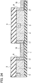
Fig. 31 is a sectional view seen in the direction A-A inFig. 30 . -
Fig. 32 is a perspective view illustrating a method of manufacturing the semiconductor device according to the second modification of the second embodiment of the present invention. -
Fig. 33 is a sectional view seen in the direction A-A inFig. 32 . - First and second embodiments of the present invention will be described below with reference to the drawings. Throughout the drawings, the same or like portions are denoted by the same or like reference signs to omit repeated descriptions. Note that the drawings are schematic, and dimensional relations, ratios and the like may be different from actual ones. In addition, some dimensional relations and ratios may be different from one drawing to another. Further, the following embodiments are provided to present examples of a device and a method for embodying the technical concept of the present invention, and the technical concept of the present invention is not limited to the materials, shapes, structures, arrangements, and the like of constituents described below.
- Furthermore, in the embodiments below, a "first conductivity type" and a "second conductivity type" are opposite conductivity types from each other. Thus, if the first conductivity type is an n type, the second conductivity type is a p type, and if the first conductivity type is a p type, the second conductivity type is an n type. Although the following describes a case where the first conductivity type is an n type and the second conductivity type is a p type, the first conductivity type may be a p type, and the second conductivity type may be an n type. When an n type and a p type are interchanged, the polarities of applied voltage are also inverted.
-
Fig. 1 is a perspective view schematically illustrating the configuration of a semiconductor device according to a first embodiment of the present invention.Fig. 2A is a top view corresponding toFig. 1 .Fig. 2B is a sectional view seen in the direction A-A inFig. 1 .Fig. 2C is a sectional view seen in the direction B-B inFig. 1 . The first embodiment exemplifies a semiconductor device having three metal-oxide-semiconductor field-effect transistors (MOSFETs) as a plurality of semiconductor elements. More semiconductor elements may be arranged in two axis directions on a plane (the X-axis direction and the Z-axis direction). Note thatFig. 1 omits illustration of electrode wiring to facilitate an understanding. - As illustrated in
Figs. 1 and2A to 2C , the semiconductor device according to the first embodiment includes asubstrate 1, awell region 2, asource region 3, adrift region 4, adrain region 5,gate insulating films 6,gate electrodes 7,gate grooves 8,source electrodes 15, adrain electrode 16,protection regions 17, and aconnection region 18. - The
substrate 1 is a flat plate made of, for example, a semi-insulator or an insulator. Herein, an insulator means a substrate with a sheet resistance of several k Ω/sq or above, and a semi-insulator means a substrate with a sheet resistance of several tens of Ω/sq or above. For example, silicon carbide (SiC) may be used as a material for thesubstrate 1. The first embodiment describes a case where thesubstrate 1 is made of SiC, which is an insulator. Thesubstrate 1 has a thickness of, for example, approximately several tens of µm to several hundreds of µm. - The
drift region 4 is an n--type region formed on one main surface of the substrate 1 (hereinafter referred to as a "first main surface"). The impurity concentration of thedrift region 4 is higher than that of thesubstrate 1, and is, for example, approximately 1×104cm-3 to 1×1018cm-3. Thedrift region 4 is made of the same material as thesubstrate 1, and is, for example, an epitaxial growth layer made of SiC if thesubstrate 1 is made of SiC. Thedrift region 4 has a thickness of, for example, approximately a few µm to several tens of µm. - The
well region 2 is a p-type region extending within thedrift region 4 from a main surface of the drift region 4 (hereinafter referred to as a "second main surface") opposite from a main surface of thedrift region 4 in contact with the substrate 1 (hereinafter referred to as a "first main surface") to the first main surface of thedrift region 4 in a direction perpendicular to the second main surface of the drift region 4 (the Y-axis direction). Herein, "an end portion of thewell region 2" refers to a portion where the bottom surface of thewell region 2 parallel to the first main surface of thedrift region 4 intersects with an end surface of thewell region 2 facing thedrift region 4. The bottom surface of thewell region 2 may be higher or lower than the first main surface of thedrift region 4. Thewell region 2 extends in one direction parallel to the second main surface of the drift region 4 (the Z-axis direction). The impurity concentration of thewell region 2 is, for example, approximately 1×1015 cm-3 to 1×1019 cm-3. - The
source region 3 extends in thewell region 2 from the second main surface of thedrift region 4 in the direction perpendicular to the second main surface of the drift region 4 (the Y-axis direction). Thesource region 3 extends parallel to thewell region 2 in one direction parallel to the second main surface of the drift region 4 (the Z-axis direction). Thesource region 3 has the same conductivity type as thedrift region 4. The impurity concentration of thesource region 3 is higher than that of thedrift region 4, and is, for example, approximately 1×1018 cm-3 to 1×1021 cm-3. - The
source region 3 and thewell region 2 are electrically connected to thesource electrodes 15 formed at the exposed surface and have the same potential as each other. For example, a conductor containing a metal material such as nickel (Ni), a titanium (Ti), or molybdenum (Mo) is usable as a material for thesource electrodes 15. Note thatFigs. 2A and2C do not show thesource electrodes 15. - Each
gate groove 8 is, as illustrated inFig. 2B , a groove formed from the second main surface of thedrift region 4 to the first main surface of thedrift region 4 in the direction perpendicular to the second main surface of the drift region 4 (the Y-axis direction). Thegate groove 8 extends in a direction (the X-axis direction) parallel to the second main surface of thedrift region 4 and orthogonal to the direction in which thesource region 3 and thewell region 2 extend, and is in contact with thesource region 3, thewell region 2, and thedrift region 4. The bottom surface of thegate groove 8 does not need to coincide with the first main surface of thedrift region 4, and for example, may be higher than the bottom surface of thesource region 3 or coincide with the bottom surface of thesource region 3. Thegate grooves 8 are arranged in a direction (the Z-axis direction) parallel to the second main surface of thedrift region 4 and orthogonal to the direction in which thegate grooves 8 extend. - The
gate insulating film 6 is formed over the entire surface of thegate groove 8. For example, an insulator such as silicon oxide film (SiO2 film) is usable as a material for thegate insulating film 6. Thegate electrode 7 is formed in thegate groove 8, at least on the surface of thegate insulating film 6. In other words, thegate electrode 7 is formed on the surface of thegate groove 8 with thegate insulating film 6 interposed therebetween. For example, a conductor such as n-type polysilicon is usable as a material for thegate electrode 7. - The
drain region 5 is an n+-type region formed in thedrift region 4, away from thewell region 2. Thedrain region 5 extends from the second main surface of thedrift region 4 to the first main surface of thedrift region 4 in the direction perpendicular to the second main surface of the drift region 4 (the Y-axis direction). Thedrain region 5 may be shallower than the thickness of thedrift region 4. Thedrain region 5 extends in a direction in which thewell region 2 and thesource region 3 extend (the Z-axis direction). Thedrain region 5 has the same conductivity type as thedrift region 4. The impurity concentration of thedrain region 5 is higher than that of thedrift region 4 and substantially the same as that of thesource region 3, and is, for example, approximately 1×1018 cm-3 to 1×1021 cm-3. - The
drain region 5 is electrically connected to thedrain electrode 16 formed at the exposed surface. For example, a conductor containing a metal material such as nickel (Ni), a titanium (Ti), or molybdenum (Mo) is usable as a material for thedrain electrode 16. Note thatFigs. 2A and2C omit the illustration of thedrain electrode 16. - The
protection regions 17 are each a p-type region formed in thedrift region 4 on a surface of thegate insulating film 6 facing thedrain region 5. In other words, theprotection region 17 is formed in contact with an entire end surface of thegate groove 8 facing thedrain region 5. In other words, theprotection region 17 is as deep as thegate groove 8 and is as wide as thegate groove 8. Note that the widths of theprotection region 17 and thegate groove 8 are widths in a direction (the Z-axis direction) along the second main surface of thedrift region 4 and orthogonal to a main current direction (the X-axis direction). The impurity concentration of theprotection region 17 is, for example, approximately 1×1015 cm-3 to 1×1019 cm-3. - The
connection region 18 is a p-type region formed in thedrift region 4 while in contact with thewell region 2 and theprotection region 17. Theconnection region 18 is formed from the second main surface of thedrift region 4 to a depth shallower than the depth of thegate groove 8. Theconnection region 18 is formed in a range, in the direction in which thegate groove 8 extends (the X-axis direction), from the end surface of thewell region 2 facing thedrain region 5, beyond the end surface of thegate groove 8 facing thedrain region 5, to a position not beyond the end surface of theprotection region 17 facing thedrain region 5. In other words, theconnection region 18 is in contact with thegate insulating film 6 forming side surfaces of thegate groove 8 along the direction in which thegate groove 8 extends (the X-axis direction). Theconnection region 18 has a higher impurity concentration than thewell region 2. The impurity concentration of theconnection region 18 is, for example, approximately 1×1015 cm-3 to 1×1019 cm-3. - The
well region 2 and theprotection region 17 are electrically connected to each other by theconnection region 18. In other words, thesource region 3, thewell region 2, thesource electrode 15, theprotection region 17, and theconnection region 18 are electrically connected to one another and have the same potential as each other. - Next, a description is given of the basic operation of the semiconductor device according to the first embodiment of the present invention.
- The semiconductor device according to the first embodiment functions as a transistor when the potential of the
gate electrode 7 is controlled based on the potential of thesource electrode 15 with a positive potential applied to thedrain electrode 16. In other words, when the voltage between thegate electrode 7 and thesource electrode 15 is equal to or above a predetermined threshold, an inversion layer to be a channel is formed in thewell region 2 located at a side surface of eachgate electrode 7, bringing the semiconductor device to an ON state, so that currents flow from thedrain electrode 16 to thesource electrode 15. Specifically, electrons flow from thesource electrode 15 to thesource region 3 and then from thesource region 3 into thedrift region 4 via the channel. Further, the electrons flow from thedrift region 4 to thedrain region 5, and finally to thedrain electrode 16. - On the other hand, when the voltage between the
gate electrode 7 and thesource electrode 15 is equal to or below the predetermined threshold, the inversion layer in thewell region 2 disappears, bringing the semiconductor device to an OFF state, so that currents between thedrain electrode 16 and thesource electrode 15 are shut off. In this event, a high voltage of several hundreds of V to several thousands of V may be applied between the drain and the source. - In general, the voltage between the gate and the drain is withstood by the gate insulating film facing the drain region and a depletion layer spreading in the drift region. In this event, the electric field concentrates at the interface between the gate insulating film and the drift region. Since the gate insulating film is usually approximately several tens of nm, dielectric breakdown may occur.
- Since the semiconductor device according to the first embodiment includes the
protection region 17 having the same potential as thesource region 3, the depletion layer spreads to theprotection region 17 upon application of a high voltage to thedrain region 5. Then, the voltage between thegate electrode 7 and thedrain region 5 is withstood by thegate insulating film 6 facing thedrain region 5, the depletion layer in theprotection region 17, and the depletion layer in thedrift region 4. Among these, the joint interface between theprotection region 17 and thedrift region 4 experiences the strongest electric field. Thus, theprotection region 17 can protect thegate insulating film 6 from dielectric breakdown and improve voltage withstand performance. - Further, since the semiconductor according to the first embodiment includes the
connection region 18 that is in contact with thewell region 2 and theprotection region 17 and has the same conductivity type as thewell region 2 and theprotection region 17, thesource region 3 and theprotection region 17 can be electrically connected to each other. Thus, metal wiring and a contact hole for connecting theprotection region 17 are unnecessary, and the surface of theprotection region 17 does not need to be wider than a contact hole. For this reason, the element does not increase in size, and the number of elements formable per unit area does not decrease. - In addition, in the semiconductor device according to the first embodiment, the surface area of the
protection region 17 does not need to be increased, and therefore theprotection region 17 is not wider than thegate groove 8. If theprotection region 17 were wider than thegate groove 8, theprotection region 17 would hinder flow of main currents from thedrain region 5 to thesource region 3 in the ON state, possibly increasing the on-resistance per unit area. In the semiconductor according to the first embodiment, theprotection region 17 can protect thegate insulating film 6 without increasing on-resistance per unit area. - In addition, in the semiconductor according to the first embodiment, the
connection region 18 has a higher impurity concentration than thewell region 2, and therefore the resistance of theconnection region 18 can be reduced to improve conductivity. Thereby, in the semiconductor device according to the first embodiment, the potential of thesource region 3 and theprotection region 17 can be fixed more easily, and the risk of malfunctioning can be reduced. - In addition, in the semiconductor device according to the first embodiment, the
substrate 1 is made of an insulator or a semi-insulator, and the end portion of thewell region 2 is in contact with thesubstrate 1. Thereby, electric field concentration at the end portion of thewell region 2 can be reduced, and voltage withstand performance can be further improved. - In addition, in the semiconductor device according to the first embodiment, the
substrate 1 and thedrift region 4 are formed of the same material, and therefore the possibility of warpage due to stress can be reduced, and reliability of the element can be improved. -
Fig. 3 is a perspective view illustrating a semiconductor device according to a first modification of the first embodiment of the present invention. The semiconductor device according to the first modification of the first embodiment differs from the first embodiment described above in that a plurality of semiconductor devices and a plurality of semiconductor devices are connected to each other in parallel. Configurations, operations, and advantageous effects not described in the first modification of the first embodiment are substantially the same as those described in the first embodiment, and are omitted to avoid repetition. - In the first modification of the first embodiment, a plurality of
well regions 2 are arranged parallel to and away from one another, in a direction (the X-axis direction) parallel to the second main surface of thedrift region 4 and orthogonal to the direction in which thewell regions 2 extend (the Z-axis direction). In therespective well regions 2, a plurality ofsource regions 3 are formed. A plurality ofdrain regions 5 are formed so that eachdrain region 5 may be between adjacent ones of thewell regions 2 with spaces from thewell regions 2. - The
gate grooves 8 extend in a direction (the X-axis direction) which is parallel to the second main surface of thedrift region 4 and in which thewell regions 2 are arranged, thegate grooves 8 being in contact with thedrift region 4 at both sides in the direction (the X-axis direction) in which thewell regions 2 are arranged. In other words, thegate grooves 8 penetrate thewell region 2 and thesource region 3. - The
protection regions 17 are formed to be in contact with both end surfaces of eachgate groove 8 facing therespective drain regions 5. Theconnection regions 18 are formed in areas from both end surfaces of eachwell region 2 in the direction in which thewell regions 2 are arranged (the X-axis direction) to positions in contact with theprotection regions 17 located on both sides. - Next, with reference to
Figs. 4 to 11 , a description is given of an example method of manufacturing the semiconductor device according to the first modification of the first embodiment. To facilitate an understanding,Figs. 4 to 11 show unit element cells connected in parallel in the region D inFig. 3 . - First, as illustrated in
Fig. 4 , asubstrate 1 is prepared. Thesubstrate 1 is an insulating substrate made of non-doped SiC, and has a thickness of approximately several tens of µm to several hundreds of µm. An n--type SiC epitaxial layer is formed on thesubstrate 1 as adrift region 4. While there are several polytypes of SiC, the representative 4H is used herein. For example, thedrift region 4 formed has an impurity concentration of 1×1014 cm-3 to 1×1018 cm-3 and a thickness of a few µm to several tens of µm. - Next, as illustrated in
Fig. 5 , p-type well regions 2, n+-type source regions 3, n+-type drain regions 5, p-type protection regions 17, and p-type connection regions 18 are formed on thedrift region 4. The order of the formation is as follows. Preferably, thewell regions 2 are formed first. Thereafter, thesource regions 3 and thedrain regions 5 may be formed simultaneously. Thewell regions 2, thesource regions 3, thedrain regions 5, theprotection regions 17, and theconnection region 18 are formed using ion implantation. - To mask regions not to be ion-implanted, a mask material may be formed on the
drift region 4 by the following steps. A silicon oxide film (SiO2 film) can be used as the mask material, and thermal chemical vapor deposition (thermal CVD) or plasma CVD can be used as a deposition method. Next, a resist is applied to the mask material and is patterned using typical photolithography. With the patterned resist used as a mask, the mask material is partially and selectively removed by etching. As the etching method, wet etching using hydrofluoric acid or dry etching such as reactive ion etching (RIE) can be used. Next, the resist is removed using oxygen plasma, sulfuric acid, or the like. - Thereafter, with the mask material used as a mask, p-type and n-type impurities are ion-implanted to the
drift region 4 to form the p-type well regions 2,protection regions 17, andconnection regions 18, as well as the n+-type source regions 3 anddrain regions 5. For example, aluminum (Al) or boron (B) can be used as the p-type impurities. Further, for example, nitrogen (N) can be used as the n-type impurities. In this step, when the ion implantation is performed with the base temperature being heated at approximately 300 °C to 600 °C, crystal defects occurring in the implanted region can be reduced. After the ion implantation, the mask material is removed using, for example, wet etching with hydrofluoric acid. - Next, the ion-implanted impurities are annealed to be activated. The annealing temperature is, for example, approximately 1700 °C, and argon (Ar) or nitrogen (N2) can be favorably used as the atmosphere. Further, favorable impurity concentrations of the
source regions 3 and thedrain regions 5 formed by the above method are 1×1018 cm-3 to 1×1021 cm-3, and their implantation depths are shallower than the first main surface of thedrift region 4. Further, favorable impurity concentrations of thewell regions 2, theprotection regions 17, and theconnection regions 18 are 1×1015 cm-3 to 1×1019 cm-3. The implantation depths of thewell regions 2 and theprotection region 17 may be deeper than the first main surface of thedrift region 4, so that the end portions of thewell regions 2 reach the inside of thesubstrate 1. The implantation depth of theconnection region 18 is shallower than the first main surface of thedrift region 4. For example, the implantation energy may be MKeV level or higher when the thickness of thedrift region 4 is 1 µm or larger. - Next, as illustrated in
Fig. 6 , amask material 9 is formed to formgate grooves 8 in thedrift region 4. A patterned insulating film can be used as themask material 9, like the mask material used in the step described usingFig. 5 . Next, thegate grooves 8 are formed with themask material 9 used as a mask. Note that the structure after the formation of thegate grooves 8 is not shown. Dry etching such as RIE is favorably used to form thegate grooves 8. Thegate grooves 8 are formed shallower than thesource regions 3. After the formation of thegate grooves 8, themask material 9 is removed. For example, when themask material 9 is a silicon oxide film, themask material 9 is removed by hydrofluoric acid cleaning. - Next, as illustrated in
Figs. 7 and8 , agate insulating film 6 andgate electrodes 7 are formed. Specifically, first, thegate insulating film 6 is formed on thedrift region 4 and the surfaces of thegate grooves 8 by the thermal oxidation method or the deposition method. For example, in the case of thermal oxidation, when the base is heated at a temperature of approximately 1100 °C in an oxygen atmosphere, a silicon oxide film is formed on all the portion of the base that is in contact with oxygen. After the formation of thegate insulating film 6, annealing at approximately 1000 °C may be performed in an atmosphere of nitrogen, argon, nitrous oxide (N2O), or the like to reduce the interface state of the interfaces between thewell regions 2 and thegate insulating film 6. - Thereafter, a material to be the
gate electrodes 7 is deposited on the surface of thegate insulating film 6. Polysilicon is usable as the material for thegate electrodes 7. The following description assumes that polysilicon is used to form thegate electrodes 7. For the polysilicon deposition, low-pressure CVD may be used. Eachgate groove 8 can be completely embedded with the polysilicon when the thickness of the polysilicon deposited is more than half the width of thegate groove 8. For example, when the width of thegate groove 8 is 2 µm, the thickness of polysilicon is more than 1 µm. After the polysilicon deposition, annealing is performed at approximately 950 °C in an atmosphere of phosphoryl chloride (POCl3), thereby forming n-type polysilicon and giving conductivity to thegate electrodes 7. - Next, the polysilicon of the
gate electrodes 7 is etched by isotropic etching or anisotropic etching. The amount of etching is set so that the polysilicon may remain in thegate grooves 8. For example, when the width of eachgate groove 8 is 2 µm and the thickness of the polysilicon deposited is 1.5 µm, a desirable amount of etching is 1.5 µm. Note that it is not problematic even if the polysilicon is over-etched by several percentage relative to the polysilicon thickness 1.5 µm due to etching control.Figs. 7 and8 illustrate the structure after the etching of the polysilicon. Note that, to facilitate an understanding,Fig. 7 does not show the insulating film formed on the surface of thedrift region 4 in the formation of thegate insulating film 6, but actually, the insulating film may be formed on the surface of thedrift region 4 as well, as illustrated inFig. 8 . - Next, as illustrated in
Figs. 9 and10 , aninterlayer insulating film 10 is formed, and contact holes 11 for electrodes are formed. To facilitate an understanding,Fig. 10 does not show the interlayer insulatingfilm 10 and shows only the positions of the contact holes 11. Generally, a silicon oxide film is favorable as theinterlayer insulating film 10, and a usable deposition method is thermal CVD or plasma CVD. After the deposition of theinterlayer insulating film 10, a resist is applied to theinterlayer insulating film 10 and is patterned using typical photolithography (not shown). With the patterned resist used as a mask, theinterlayer insulating film 10 is partially and selectively removed by wet etching using hydrofluoric acid or dry etching such as reactive ion etching (RIE) to form the contact holes 11. Thereafter, the resist is removed using oxygen plasma or sulfuric acid. - Next, as illustrated in
Fig. 11 ,gate wiring 12,source wiring 13, and drainwiring 14 are formed. To facilitate an understanding,Fig. 11 does not show interlayer illustrating films between thedrift region 4, thegate wiring 12, thesource wiring 13, and thedrain wiring 14. As a wiring material, a metal material such as titanium (Ti), nickel (Ni), or molybdenum (Mo) is usable. The following description assumes that Ti is used to form thegate wiring 12, thesource wiring 13, and thedrain wiring 14. First, Ti is deposited using metal organic chemical vapor deposition (MOCVD) or the like. Next, with a resist or the like used as a mask, the Ti is selectively etched. Next, an interlayer insulating film between thegate wiring 12 and thesource wiring 13 is deposited, and contact holes are formed. Sputtering or the like is favorably used for the deposition of the interlayer insulating film, and the contact holes can be formed in the same manner as the step described usingFigs. 9 and10 . Next, a metal material to be thesource wiring 13 is deposited and then etched by the same method used for the formation of thegate wiring 12. Subsequently, an interlayer insulating film between thesource wiring 13 and thedrain wiring 14 is deposited, contact holes are formed, and a metal material to be thedrain wiring 14 is deposited.Fig. 11 shows a semiconductor device after the formation of thedrain wiring 14. The semiconductor device illustrated inFig. 3 is completed after the steps described above. - The method of manufacturing the semiconductor device according to the first modification of the first embodiment can obtain a semiconductor device illustrated in
Fig. 3 with improved voltage withstand performance without being increased in size. - Further, in the semiconductor device according to the first modification of the first embodiment, the
protection regions 17 adjacent in the direction in which main currents flow (the X-axis direction) and thedrift region 4 sandwiched by theseprotection regions 17 are fully depleted at a predetermined drain voltage or higher. Thereby, voltage withstand performance can be improved even more. -
Fig. 12 is a perspective view illustrating a semiconductor device according to a second modification of the first embodiment of the present invention.Fig. 13 is a top view corresponding toFig. 12 . The semiconductor device according to the second modification of the first embodiment differs from the above first embodiment in that theconnection regions 18 are in contact with thesource electrodes 15. Configurations, operations, and advantageous effects not described in the second modification of the first embodiment are substantially the same as those in the above embodiment and are omitted to avoid repetition. - In the second modification of the first embodiment, the
source electrodes 15 are in contact with the upper surfaces of thewell region 2 and thesource region 3 and the upper surface of theconnection region 18. Thesource electrodes 15, thewell region 2, thesource region 3, and theconnection region 18 have the same potential as each other. Thesource electrodes 15 are formed on the second main surface of thedrift region 4. Thesource electrodes 15 can be formed without any change in the process, when the step illustrated inFigs. 9 and10 also forms acontact hole 11 in an area on theconnection region 18. - Generally, since p-type SiC has relatively large resistivity, it is difficult to fix a potential. In the semiconductor element according to the second modification of the first embodiment, the
connection region 18 is in direct contact with thesource electrode 15, which makes it easy to fix the potential and possible to reduce the risk of malfunction. - Further, as illustrated in
Fig. 14 , in the second modification of the first embodiment, theconnection region 18 may be in contact with thesource electrode 15 at a position deeper than the second main surface of thedrift region 4. Such asource electrode 15 can be formed by, in the step illustrated usingFigs. 9 and10 , forming thecontact hole 11 also in an area corresponding to theconnection region 18, forming a groove shallower than theconnection region 18 by etching similar to that used for thegate groove 8, and depositing an electrode material in the groove. - The source electrode 15 formed to be in contact at a position deeper than the upper surface of the
connection region 18 is in contact not only at its bottom surface, but also at its side surfaces in the groove formed in theconnection region 18, and therefore the area of contact with theconnection region 18 is large. Thus, contact resistance is reduced, which makes it easy to fix the potential even more and possible to reduce the risk of malfunction. -
Fig. 15 is a perspective view illustrating a semiconductor device according to a second embodiment of the present invention.Fig. 16 is a sectional view seen in the direction A-A inFig. 15 . The semiconductor device according to the second embodiment differs from the above first embodiment in that theconnection region 18 is formed in contact with the bottom surface of thegate insulating film 6. Configurations, operations, and advantageous effects described in the second embodiment below are substantially the same as the above embodiment and are omitted to avoid repetition. To facilitate an understanding,Figs. 15 and16 do not show electrode wiring. - In the second embodiment, the
gate groove 8 is shallower than thedrift region 4. In other words, the bottom surface of thegate groove 8 is higher than the first main surface of thedrift region 4. Further, as illustrated inFig. 16 , theconnection region 18 is formed in contact with the bottom surface of thegate insulating film 6 facing thesubstrate 1. Theconnection region 18 extends in the direction in which thegate groove 8 extends (the X-axis direction) from the end surface of thewell region 2 facing thedrain region 5 to a position in contact with the bottom portion of theprotection region 17. Note that the width of theconnection region 18 coincides with, for example, the width of thegate groove 8. In other words, theconnection region 18 is formed within thedrift region 4 on the bottom surfaces of thegate grooves 8 and theprotection regions 17 facing thesubstrate 1, except for thewell region 2 and thesource region 3. - Next, a description is given of the basic operation of the semiconductor device according to the first embodiment of the present invention.
- Like in the first embodiment, the semiconductor device according to the second embodiment functions as a transistor when the potential of the
gate electrode 7 is controlled based on the potential of thesource electrode 15 with a positive potential applied to thedrain electrode 16. In other words, when the voltage between thegate electrode 7 and thesource electrode 15 is equal to or above a predetermined threshold, an inversion layer to be a channel is formed in thewell region 2 located at a side surface of thegate electrode 7, bringing the semiconductor device to an ON state, so that currents flow from thedrain electrode 16 to thesource electrode 15. - On the other hand, when the voltage between the
gate electrode 7 and thesource electrode 15 is equal to or below the predetermined threshold, the inversion layer in thewell region 2 disappears, bringing the semiconductor device to an OFF state, so that currents between thedrain electrode 16 and thesource electrode 15 are shut off. In this event, a high voltage of several hundreds of V to several thousands of V may be applied between the drain and the source. - As described, in the semiconductor device according to the second embodiment, the channel is formed not under the
gate groove 8 where theconnection region 18 is formed, but in thewell region 2 located at the side surface of thegate electrode 7. For this reason, theconnection region 18 does not affect the channel width during the ON state. - Since the semiconductor device according to the second embodiment includes the
protection region 17 having the same potential as thesource region 3, the depletion layer spreads to theprotection region 17 upon application of a high voltage to thedrain region 5. Then, the voltage between thegate electrode 7 and thedrain region 5 is withstood by thegate insulating film 6 facing thedrain region 5, the depletion layer in theprotection region 17, and the depletion layer in thedrift region 4. Among these, the joint interface between theprotection region 17 and thedrift region 4 experiences the strongest electric field. Thus, theprotection region 17 can protect thegate insulating film 6 from dielectric breakdown and improve voltage withstand performance. - Further, since the semiconductor according to the second embodiment includes the
connection region 18 that is in contact with thewell region 2 and theprotection region 17 and has the same conductivity type as thewell region 2 and theprotection region 17, thesource region 3 and theprotection region 17 can be electrically connected to each other. Thus, metal wiring and a contact hole for connecting theprotection region 17 are unnecessary, and the surface of theprotection region 17 does not need to be wider than a contact hole. For this reason, the element does not increase in size, and the number of elements formable per unit area does not decrease. - In addition, in the semiconductor device according to the second embodiment, the surface area of the
protection region 17 does not need to be increased, and therefore theprotection region 17 is not wider than thegate groove 8. If theprotection region 17 were wider than thegate groove 8, theprotection region 17 would hinder flow of main currents from thedrain region 5 to thesource region 3 in the ON state, possibly increasing the on-resistance per unit area. In the semiconductor according to the second embodiment, theprotection region 17 can protect thegate insulating film 6 without increasing on-resistance per unit area. - Further, since the semiconductor device according to the second embodiment includes the
connection region 18 formed in contact with the bottom surface of thegate insulating film 6, the flow of main currents is not hindered. In addition, since an inversion layer is formed in theconnection region 18 in the ON state, the channel width is increased, and on-resistance can be reduced. - In addition, since the
connection region 18 has a higher impurity concentration than thewell region 2 in the semiconductor device according to the second embodiment, resistance of theconnection region 18 can be reduced, and conductivity can be improved. Thereby, in the semiconductor device according to the second embodiment, it is easy to fix the potentials of thesource region 3 and theprotection region 17, and the risk of malfunction can be reduced. - Further, in the semiconductor device according to the second embodiment, the
substrate 1 is made of an insulator or a semi-insulator, and the end portion of thewell region 2 is in contact with thesubstrate 1. Thus, electric field concentration at the end portion of thewell region 2 can be reduced, and voltage withstand performance can be improved even more. - Further, in the semiconductor device according to the first embodiment, the
substrate 1 and thedrift region 4 are formed of the same material. Thus, the risk of warpage due to stress can be reduced, and the reliability of the element can be improved. -
Fig. 17 is a perspective view illustrating a semiconductor device according to a first modification of the second embodiment of the present invention. The semiconductor device according to the first modification of the second embodiment differs from the above second embodiment in that a plurality of semiconductor elements and a plurality of semiconductor elements are connected in parallel. Configurations, operations, and advantageous effects not described in the first modification of the second embodiment are substantially the same as those in the above second embodiment and are omitted to avoid repetition. - In the first modification of the second embodiment, a plurality of
well regions 2 are arranged parallel to and away from one another, in a direction (the X-axis direction) parallel to the second main surface of thedrift region 4 and orthogonal to the direction in which thewell regions 2 extend (the Z-axis direction). In therespective well regions 2, a plurality ofsource regions 3 are formed. A plurality ofdrain regions 5 are formed so that eachdrain region 5 may be between adjacent ones of thewell regions 2 with spaces from thewell regions 2. - The
gate grooves 8 extend in a direction (the X-axis direction) which is parallel to the second main surface of thedrift region 4 and in which thewell regions 2 are arranged, thegate grooves 8 being in contact with thedrift region 4 at both sides in the direction (the X-axis direction) in which thewell regions 2 are arranged. In other words, thegate grooves 8 penetrate thewell region 2 and thesource region 3. - The
protection regions 17 are formed to be in contact with both end surfaces of eachgate groove 8 facing therespective drain regions 5. Theconnection regions 18 are formed in areas under thegate grooves 8 from both end surfaces of eachwell region 2 in the direction in which thewell regions 2 are arranged (the X-axis direction) to positions in contact with theprotection regions 17 located on both sides. - Next, with reference to
Figs. 18 to 29 , a description is given of an example method of manufacturing the semiconductor device according to the first modification of the first embodiment. To facilitate an understanding,Figs. 18 to 29 show unit element cells connected in parallel in the region D inFig. 17 . - First, as illustrated in
Fig. 18 , asubstrate 1 is prepared. Thesubstrate 1 is an insulating substrate made of non-doped SiC, and has a thickness of approximately several tens of µm to several hundreds of µm. An n--type SiC epitaxial layer is formed on thesubstrate 1 as adrift region 4. While there are several polytypes of SiC, the representative 4H is used herein. For example, thedrift region 4 formed has an impurity concentration of 1×1014 cm-3 to 1×1018 cm-3 and a thickness of a few µm to several tens of µm. - Next, as illustrated in
Fig. 19 , p-type well regions 2, n+-type source regions 3, and n+-type drain regions 5 are formed on thedrift region 4. The order of the formation is as follows. Preferably, thewell regions 2 are formed first. Thereafter, thesource regions 3 and thedrain regions 5 may be formed simultaneously. Thewell regions 2, thesource regions 3, and thedrain regions 5 are formed using ion implantation. - To mask regions not to be ion-implanted, a mask material may be formed on the
drift region 4 by the following steps. A silicon oxide film (SiO2 film) can be used as the mask material, and thermal CVD or plasma CVD can be used as a deposition method. Next, a resist is applied to the mask material and is patterned using typical photolithography. With the patterned resist used as a mask, the mask material is partially and selectively removed by etching. As the etching method, wet etching using hydrofluoric acid or dry etching such as reactive ion etching (RIE) can be used. Next, the resist is removed using oxygen plasma, sulfuric acid, or the like. - Thereafter, with the mask material used as a mask, p-type and n-type impurities are ion-implanted to the
drift region 4 to form and the p-type well regions 2 and the n+-type source regions 3 anddrain regions 5. For example, aluminum (Al) or boron (B) can be used as the p-type impurities. Further, for example, nitrogen (N) can be used as the n-type impurities. In this step, when the ion implantation is performed with the base temperature being heated at approximately 300 °C to 600 °C, crystal defects occurring in the implanted region can be reduced. After the ion implantation, the mask material is removed using, for example, wet etching with hydrofluoric acid. - Favorable impurity concentrations of the
source regions 3 and thedrain regions 5 formed by the above method are 1×1018 cm-3 to 1×1021 cm-3, and their implantation depths are shallower than the first main surface of thedrift region 4. Further, the impurity concentration of thewell regions 2 is favorably 1×1015 cm-3 to 1×1019 cm-3. The implantation depth of thewell regions 2 may be deeper than the first main surface of thedrift region 4, so that the end portions of thewell regions 2 reach the inside of thesubstrate 1. For example, the implantation energy may be MKeV level or higher when the thickness of thedrift region 4 is 1 µm or larger. - Next, as illustrated in
Fig. 20 , amask material 9 is formed to formgate grooves 8 in thedrift region 4. A patterned insulating film can be used as themask material 9, like the mask material used in the step described usingFig. 19 . - Next, as illustrated in
Figs. 21 and22 , thegate grooves 8 are formed with themask material 9 used as a mask. Dry etching such as RIE is favorably used to form thegate grooves 8. Thegate grooves 8 are formed shallower thansource regions 3 herein, but may be formed deeper than thesource regions 3. - Next, as illustrated in
Figs. 23 and24 , with themask material 9 still used as a mask, p-type protection regions 17 andconnection regions 18 are formed by self-alignment. By ion implantation in the direction perpendicular to thesubstrate 1, theconnection regions 18 can be easily formed in contact with the bottom surfaces of thegate grooves 8 without positional displacement. By ion implantation in a direction parallel to a section shown inFig. 24 (the X-Y plane) and having a certain angle relative to thesubstrate 1, theprotection regions 17 can be easily formed without positional displacement only at the end surfaces of thegate grooves 8 facing thedrain regions 5. The angle relative to thesubstrate 1 is preferably 1° to 45° from the perspective of implantation depth. For example, aluminum (Al) or boron (B) can be used as the p-type impurities. The impurity concentration of theconnection regions 18 is higher than that of thewell regions 2, and the implantation depth is preferably approximately several hundred of nm. When the ion implantation is performed with the base temperature heated at approximately 300 °C to 600 °C, crystal defects occurring in the implanted region can be reduced. After the ion implantation, themask material 9 is removed using, for example, hydrofluoric acid cleaning if themask material 9 is a silicon oxide film. - Next, the ion-implanted impurities are annealed to be activated. The annealing temperature is, for example, approximately 1700 °C, and argon (Ar) or nitrogen (N2) can be favorably used as the atmosphere. By this activation, the
well regions 2, thesource regions 3, thedrain regions 5, theprotection regions 17, and theconnection regions 18 are formed. - Next, as illustrated in
Figs. 25 and26 , agate insulating film 6 andgate electrodes 7 are formed. Specifically, first, thegate insulating film 6 is formed on thedrift region 4 and the surfaces of thegate grooves 8 by the thermal oxidation method or the deposition method. For example, in the case of thermal oxidation, when the base is heated at a temperature of approximately 1100 °C in an oxygen atmosphere, a silicon oxide film is formed on all the portion of the base that is in contact with oxygen. After the formation of thegate insulating film 6, annealing at approximately 1000 °C may be performed in an atmosphere of nitrogen, argon, nitrous oxide (N2O), or the like to reduce the interface state of the interfaces between thewell regions 2 and thegate insulating film 6. - Thereafter, a material to be the
gate electrodes 7 is deposited on the surface of thegate insulating film 6. Polysilicon is usable as the material for thegate electrodes 7. The following description assumes that polysilicon is used to form thegate electrodes 7. For the polysilicon deposition, low-pressure CVD may be used. Eachgate groove 8 can be completely embedded with the polysilicon when the thickness of the polysilicon deposited is more than half the width of thegate groove 8. For example, when the width of thegate groove 8 is 2 µm, the thickness of polysilicon is more than 1 µm. After the polysilicon deposition, annealing is performed at approximately 950 °C in an atmosphere of phosphoryl chloride (POCl3), thereby forming n-type polysilicon and giving conductivity to thegate electrodes 7. - Next, the polysilicon of the
gate electrodes 7 is etched by isotropic etching or anisotropic etching. The amount of etching is set so that the polysilicon may remain in thegate grooves 8. For example, when the width of eachgate groove 8 is 2 µm and the thickness of the polysilicon deposited is 1.5 µm, a desirable amount of etching is 1.5 µm. Note that it is not problematic even if the polysilicon is over-etched by several percentage relative to the polysilicon thickness 1.5 µm due to etching control.Figs. 25 and26 illustrate the structure after the etching of the polysilicon. Note that, to facilitate an understanding,Fig. 25 does not show the insulating film formed on the surface of thedrift region 4 in the formation of thegate insulating film 6, but actually, the insulating film may be formed on the surface of thedrift region 4 as well, as illustrated inFig. 26 . - Next, as illustrated in
Figs. 27 and28 , aninterlayer insulating film 10 is formed, and contact holes 11 for electrodes are formed. To facilitate an understanding,Fig. 27 does not show the interlayer insulatingfilm 10 and shows only the positions of the contact holes 11. Generally, a silicon oxide film is favorable as theinterlayer insulating film 10, and a usable deposition method is thermal CVD or plasma CVD. After the deposition of theinterlayer insulating film 10, a resist is applied to theinterlayer insulating film 10 and is patterned using typical photolithography (not shown). With the patterned resist used as a mask, theinterlayer insulating film 10 is partially and selectively removed by wet etching using hydrofluoric acid or dry etching such as reactive ion etching (RIE) to form the contact holes 11. Thereafter, the resist is removed using oxygen plasma or sulfuric acid. - Next, as illustrated in
Fig. 29 ,gate wiring 12,source wiring 13, and drainwiring 14 are formed. To facilitate an understanding,Fig. 29 does not show interlayer illustrating films between thedrift region 4, thegate wiring 12, thesource wiring 13, and thedrain wiring 14. As a wiring material, a metal material such as titanium (Ti), nickel (Ni), or molybdenum (Mo) is usable. The following description assumes that Ti is used to form thegate wiring 12, thesource wiring 13, and thedrain wiring 14. First, Ti is deposited using metal organic chemical vapor deposition (MOCVD) or the like. Next, with a resist or the like used as a mask, the Ti is selectively etched. Next, an interlayer insulating film between thegate wiring 12 and thesource wiring 13 is deposited, and contact holes are formed. Sputtering or the like is favorably used for the deposition of the interlayer insulating film, and the contact holes can be formed in the same manner as the step described usingFigs. 27 and28 . Next, a metal material to be thesource wiring 13 is deposited and then etched by the same method used for the formation of thegate wiring 12. Subsequently, an interlayer insulating film between thesource wiring 13 and thedrain wiring 14 is deposited, contact holes are formed, and a metal material to be thedrain wiring 14 is deposited.Fig. 29 shows a semiconductor device after the formation of thedrain wiring 14. The semiconductor device illustrated inFig. 17 is completed after the steps described above. - The method of manufacturing the semiconductor device according to the first modification of the second embodiment can obtain a semiconductor device illustrated in
Fig. 17 with improved voltage withstand performance without being increased in size. - Further, in the semiconductor device according to the first modification of the second embodiment, the
protection regions 17 adjacent in the direction in which main currents flow (the X-axis direction) and thedrift region 4 sandwiched by theseprotection regions 17 are fully depleted at a predetermined drain voltage or higher. Thereby, voltage withstand performance can be improved even more. -
Fig. 30 is a perspective view illustrating a semiconductor device according to a second modification of the second embodiment of the present invention.Fig. 31 is a sectional view seen in the direction A-A inFig. 30 . The semiconductor device according to the second modification of the second embodiment differs from the above second embodiment in that at least part of theprotection regions 17 and of theconnection regions 18 are formed within thesubstrate 1. Configurations, operations, and advantageous effects not described in the second modification of the second embodiment are substantially the same as those in the above embodiment and are omitted to avoid repetition. - In the second modification of the second embodiment, the bottom surface of each
gate groove 8 is situated at the first main surface of thesubstrate 1 or inside thesubstrate 1. In addition, the depths of thewell region 2 and thedrain region 5 are larger than the thickness of thedrift region 4. Specifically, in a direction (the Y-axis direction) perpendicular to the second main surface of thedrift region 4, the end surfaces of thewell region 2 and thedrain region 5 extend into thesubstrate 1. Similarly, the depth of thesource region 3 may be larger than the thickness of thedrift region 4. Theconnection region 18 is formed within thesubstrate 1, on the bottom surfaces of thegate groove 8 and theprotection region 17 facing thesubstrate 1, except for thewell region 2 and thesource region 3. Thereby, inside thesubstrate 1, theconnection region 18 is electrically connected to thewell region 2 and theprotection region 17. - To manufacture the semiconductor device of the second modification of the second embodiment, as illustrated in
Figs. 32 and33 , with amask material 9 used as a mask, thegate grooves 8 are formed so that their bottom surfaces reach the first main surface of thesubstrate 1 or the inside of thesubstrate 1. Dry etching such as RIE is favorably used to form thegate grooves 8. Thereafter, as described usingFigs. 23 and24 , with themask material 9 still used as a mask, p-type protection regions 17 andconnection regions 18 can be formed by self-alignment. By ion implantation in the direction perpendicular to thesubstrate 1, theconnection regions 18 can be easily formed inside thesubstrate 1, in contact with the bottom surfaces of thegate grooves 8 without positional displacement. By ion implantation in a direction parallel to a section shown inFig. 33 and having a certain angle relative to thesubstrate 1, theprotection regions 17 can be easily formed without positional displacement with part thereof reaching the inside of thesubstrate 1. Note that the configuration illustrated inFigs. 32 and33 corresponds to the configuration illustrated inFigs. 21 and22 , and the step described using inFigs. 32 and33 corresponds to the step described usingFigs. 21 and22 . - According to the semiconductor device according to the second modification of the second embodiment, at least part of the
connection region 18 is formed inside thesubstrate 1 made of an insulator or a semi-insulator. Thereby, the junction capacitance between theconnection region 18 and thedrift region 4 is reduced, and thus responsiveness of the semiconductor device improves to make high-speed operation possible. - Further, in the semiconductor device according to the second modification of the second embodiment, at least part of the
protection region 17 is formed inside thesubstrate 1. Thereby, electric field concentration at the end portion of theprotection region 17 can be mitigated, and voltage withstand performance can be improved even more. - Furthermore, in the semiconductor device according to the second modification of the second embodiment, the
substrate 1 and thedrift region 4 are made of the same material. Thus, even if thewell regions 2 or theprotection regions 17 are formed deeper than the thickness of thedrift region 4, they can be easily formed with one type of p-type impurities. - As described above, the present invention has been described using the above embodiments, but it should not be understood that the description and drawings which constitute part of this disclosure limit the present invention. From this disclosure, various alternative embodiments, examples, and operation techniques will be easily found by those skilled in the art.
- For example, although the first and second embodiments describe a case of manufacturing a semiconductor device on the
substrate 1 made of SiC, the material of thesubstrate 1 is not limited to SiC. For example, as the material of thesubstrate 1, a semiconductor having a wide bandgap can be used. Examples of a semiconductor with a wide bandgap include gallium nitride (GaN), diamond, zinc oxide (ZnO), and aluminum gallium nitride (AlGaN). - In addition, although the first and second embodiments describe a case of using n-type polysilicon for the
gate electrodes 7, p-type polysilicon may be used. Further, thegate electrodes 7 may be a different semiconductor material, or a different conductive material such as a metal material. For example, p-type polysilicon carbide, silicon germanium (SiGe), aluminum (Al), or the like can be used as a material for thegate electrode 7. Similarly, as the materials for thesource electrode 15 and thedrain electrode 16, metal may be used, or alloys of a semiconductor and a metal or other conductors may be used. - In addition, although the first and second embodiments describe a case of using a silicon oxide film as the
gate insulating film 6, a silicon nitride film may be used, or a stack of a silicon oxide film and a silicon nitride film may be used. If thegate insulating film 6 is a silicon nitride film and isotropic etching is performed, the etching can be performed with, for example, cleaning with phosphoric acid heated to 160 °C. - In addition, although the first and second embodiments describe a case of forming the
drift region 4 by epitaxial growth, thedrift region 4 may be formed by implantation of n-type impurities into an insulating substrate made of SiC or the like. - In addition, in the first and second embodiments, the
substrate 1 may be formed of an n-type semiconductor having a lower impurity concentration than thedrift region 4. Thereby, when the semiconductor device is in the ON state, currents flow inside thesubstrate 1, and the path for currents widens, increasing currents. If thesubstrate 1 were a p-type semiconductor, a depletion layer widens in thedrift region 4 to narrow the current path, decreasing currents. In other words, when thesubstrate 1 has the same conductivity type as thedrift region 4, currents increase, and loss is decreased. - In addition, although the first and second embodiments describe a case where a MOSFET is an example of a semiconductor device, it goes without saying that the semiconductor devices according to the embodiments of the present invention are applicable to an insulated gate bipolar transistor (IGBT) or a thyristor.
- In addition, terms such as "parallel", "perpendicular", and "orthogonal" in the first and second embodiments are not based on complete topology, and allow incomplete topology for the reasons of photolithography or other processes.
- Additionally, the present invention naturally includes various embodiments which are not described herein, such as configurations in which the above configurations are applied to one another. Accordingly, the technical scope of the present invention should be determined only by the matters to define the invention in the scope of claims regarded as appropriate based on the description.
-
- 1
- substrate
- 2
- well region
- 3
- source region
- 4
- drift region
- 5
- drain region
- 6
- gate insulating film
- 7
- gate electrode
- 8
- gate groove
- 15
- source electrode
- 16
- drain electrode
- 17
- protection region
- 18
- connection region
Claims (10)
- A semiconductor device comprising:a substrate;a drift region of a first conductivity type formed on a first main surface of the substrate and having a higher impurity concentration than the substrate;a well region of a second conductivity type extending in the drift region from a second main surface of the drift region in a direction perpendicular to the second main surface, the second main surface being opposite from a first main surface of the drift region in contact with the substrate;a source region of the first conductivity type extending in the well region from the second main surface in the perpendicular direction;a gate groove formed from the second main surface in the perpendicular direction and extending in contact with the source region, the well region in a direction parallel to the second main surface, and the drift region;a drain region of the first conductivity type formed away from the well region in the drift region and extending from the second main surface in the perpendicular direction;a gate insulating film formed on a surface of the gate groove;a gate electrode formed on a surface of the gate insulating film;a source electrode electrically connected to the source region and the well region;a drain electrode electrically connected to the drain region;a protection region of the second conductivity type formed in the drift region, on a surface of the gate insulating film facing the drain region; anda connection region of the second conductivity type formed in the drift region while being in contact with the well region and the protection region, whereinthe well region and the protection region are electrically connected to each other by the connection region.
- The semiconductor device according to claim 1, wherein the connection region is formed in contact with a bottom surface of the gate insulating film facing the substrate.
- The semiconductor device according to claim 1 or 2, wherein at least part of the connection region is formed inside the substrate.
- The semiconductor device according to any one of claims 1 to 3, wherein at least part of the protection region is formed inside the substrate.
- The semiconductor device according to any one of claims 1 to 4, wherein the connection region has a higher impurity concentration than the well region.
- The semiconductor device according to any one of claims 1 to 5, wherein the connection region is in contact with the source electrode.
- The semiconductor device according to claim 6, wherein the connection region is in contact with the source electrode at a position deeper than the second main surface.
- The semiconductor device according to any one of claims 1 to 7, comprising a plurality of the protection regions, wherein the adjacent protection regions and the drift region sandwiched by the adjacent protection regions are fully depleted at a predetermined voltage.
- The semiconductor device according to any one of claims 1 to 8, wherein the substrate is made of an insulator or a semi-insulator.
- The semiconductor device according to any one of claims 1 to 9, wherein the drift region and the substrate are formed of the same material.
Applications Claiming Priority (1)
| Application Number | Priority Date | Filing Date | Title |
|---|---|---|---|
| PCT/JP2016/065909 WO2017208301A1 (en) | 2016-05-30 | 2016-05-30 | Semiconductor device |
Publications (3)
| Publication Number | Publication Date |
|---|---|
| EP3467869A1 true EP3467869A1 (en) | 2019-04-10 |
| EP3467869A4 EP3467869A4 (en) | 2019-05-22 |
| EP3467869B1 EP3467869B1 (en) | 2020-05-06 |
Family
ID=60479193
Family Applications (1)
| Application Number | Title | Priority Date | Filing Date |
|---|---|---|---|
| EP16903929.4A Active EP3467869B1 (en) | 2016-05-30 | 2016-05-30 | Semiconductor device |
Country Status (11)
| Country | Link |
|---|---|
| US (1) | US10886401B2 (en) |
| EP (1) | EP3467869B1 (en) |
| JP (1) | JP6610781B2 (en) |
| KR (1) | KR101965550B1 (en) |
| CN (1) | CN109219869B (en) |
| BR (1) | BR112018074758B1 (en) |
| CA (1) | CA3025767C (en) |
| MX (1) | MX2018014593A (en) |
| MY (1) | MY193292A (en) |
| RU (1) | RU2702405C1 (en) |
| WO (1) | WO2017208301A1 (en) |
Cited By (1)
| Publication number | Priority date | Publication date | Assignee | Title |
|---|---|---|---|---|
| US11881526B2 (en) | 2020-11-09 | 2024-01-23 | Nissan Motor Co., Ltd. | Semiconductor device and method for manufacturing same |
Families Citing this family (1)
| Publication number | Priority date | Publication date | Assignee | Title |
|---|---|---|---|---|
| JP6620889B2 (en) * | 2016-08-10 | 2019-12-18 | 日産自動車株式会社 | Semiconductor device |
Family Cites Families (8)
| Publication number | Priority date | Publication date | Assignee | Title |
|---|---|---|---|---|
| JP3356162B2 (en) * | 1999-10-19 | 2002-12-09 | 株式会社デンソー | Semiconductor device and manufacturing method thereof |
| US20060038223A1 (en) * | 2001-07-03 | 2006-02-23 | Siliconix Incorporated | Trench MOSFET having drain-drift region comprising stack of implanted regions |
| DE102006053145B4 (en) | 2005-11-14 | 2014-07-10 | Denso Corporation | Semiconductor device with separation region |
| JP2011054881A (en) * | 2009-09-04 | 2011-03-17 | Toshiba Corp | Semiconductor device |
| JP5762689B2 (en) * | 2010-02-26 | 2015-08-12 | 株式会社東芝 | Semiconductor device |
| CN103493208B (en) * | 2011-04-19 | 2017-03-22 | 日产自动车株式会社 | Semiconductor device and method for producing same |
| WO2014122919A1 (en) | 2013-02-05 | 2014-08-14 | 三菱電機株式会社 | Insulating gate-type silicon carbide semiconductor device and method for manufacturing same |
| WO2015008550A1 (en) * | 2013-07-19 | 2015-01-22 | 日産自動車株式会社 | Semiconductor device, and method for manufacturing same |
-
2016
- 2016-05-30 RU RU2018146542A patent/RU2702405C1/en active
- 2016-05-30 MY MYPI2018002058A patent/MY193292A/en unknown
- 2016-05-30 JP JP2018520069A patent/JP6610781B2/en active Active
- 2016-05-30 WO PCT/JP2016/065909 patent/WO2017208301A1/en unknown
- 2016-05-30 BR BR112018074758-0A patent/BR112018074758B1/en active IP Right Grant
- 2016-05-30 EP EP16903929.4A patent/EP3467869B1/en active Active
- 2016-05-30 CN CN201680086244.3A patent/CN109219869B/en active Active
- 2016-05-30 KR KR1020187037588A patent/KR101965550B1/en active IP Right Grant
- 2016-05-30 MX MX2018014593A patent/MX2018014593A/en active IP Right Grant
- 2016-05-30 CA CA3025767A patent/CA3025767C/en active Active
- 2016-05-30 US US16/305,170 patent/US10886401B2/en active Active
Cited By (1)
| Publication number | Priority date | Publication date | Assignee | Title |
|---|---|---|---|---|
| US11881526B2 (en) | 2020-11-09 | 2024-01-23 | Nissan Motor Co., Ltd. | Semiconductor device and method for manufacturing same |
Also Published As
| Publication number | Publication date |
|---|---|
| CN109219869A (en) | 2019-01-15 |
| JPWO2017208301A1 (en) | 2019-03-28 |
| BR112018074758B1 (en) | 2022-08-16 |
| MX2018014593A (en) | 2019-03-14 |
| CA3025767C (en) | 2019-07-23 |
| EP3467869A4 (en) | 2019-05-22 |
| US10886401B2 (en) | 2021-01-05 |
| EP3467869B1 (en) | 2020-05-06 |
| CA3025767A1 (en) | 2017-12-07 |
| RU2702405C1 (en) | 2019-10-08 |
| KR20190011773A (en) | 2019-02-07 |
| BR112018074758A2 (en) | 2019-03-06 |
| CN109219869B (en) | 2019-11-19 |
| WO2017208301A1 (en) | 2017-12-07 |
| JP6610781B2 (en) | 2019-11-27 |
| KR101965550B1 (en) | 2019-04-03 |
| US20190341486A1 (en) | 2019-11-07 |
| MY193292A (en) | 2022-10-03 |
Similar Documents
| Publication | Publication Date | Title |
|---|---|---|
| EP2701201B1 (en) | Semiconductor device | |
| WO2010110246A1 (en) | Semiconductor device | |
| EP3024018B1 (en) | Semiconductor device | |
| CN110291620B (en) | Semiconductor device and method for manufacturing semiconductor device | |
| US9178055B2 (en) | Semiconductor device | |
| EP3467869B1 (en) | Semiconductor device | |
| EP3499549B1 (en) | Semiconductor device | |
| WO2022096908A1 (en) | Semiconductor device and method for manufacturing same | |
| JP2022073551A (en) | Semiconductor device and manufacturing method for the same | |
| JP6286824B2 (en) | Semiconductor device and manufacturing method thereof |
Legal Events
| Date | Code | Title | Description |
|---|---|---|---|
| STAA | Information on the status of an ep patent application or granted ep patent |
Free format text: STATUS: THE INTERNATIONAL PUBLICATION HAS BEEN MADE |
|
| PUAI | Public reference made under article 153(3) epc to a published international application that has entered the european phase |
Free format text: ORIGINAL CODE: 0009012 |
|
| STAA | Information on the status of an ep patent application or granted ep patent |
Free format text: STATUS: REQUEST FOR EXAMINATION WAS MADE |
|
| 17P | Request for examination filed |
Effective date: 20181130 |
|
| AK | Designated contracting states |
Kind code of ref document: A1 Designated state(s): AL AT BE BG CH CY CZ DE DK EE ES FI FR GB GR HR HU IE IS IT LI LT LU LV MC MK MT NL NO PL PT RO RS SE SI SK SM TR |
|
| AX | Request for extension of the european patent |
Extension state: BA ME |
|
| REG | Reference to a national code |
Ref country code: DE Ref legal event code: R079 Ref document number: 602016036230 Country of ref document: DE Free format text: PREVIOUS MAIN CLASS: H01L0021336000 Ipc: H01L0029780000 |
|
| A4 | Supplementary search report drawn up and despatched |
Effective date: 20190424 |
|
| RIC1 | Information provided on ipc code assigned before grant |
Ipc: H01L 21/336 20060101ALI20190416BHEP Ipc: H01L 29/423 20060101ALI20190416BHEP Ipc: H01L 29/786 20060101ALI20190416BHEP Ipc: H01L 29/10 20060101ALI20190416BHEP Ipc: H01L 29/06 20060101ALI20190416BHEP Ipc: H01L 29/78 20060101AFI20190416BHEP |
|
| DAV | Request for validation of the european patent (deleted) | ||
| DAX | Request for extension of the european patent (deleted) | ||
| GRAP | Despatch of communication of intention to grant a patent |
Free format text: ORIGINAL CODE: EPIDOSNIGR1 |
|
| STAA | Information on the status of an ep patent application or granted ep patent |
Free format text: STATUS: GRANT OF PATENT IS INTENDED |
|
| INTG | Intention to grant announced |
Effective date: 20191218 |
|
| GRAS | Grant fee paid |
Free format text: ORIGINAL CODE: EPIDOSNIGR3 |
|
| GRAA | (expected) grant |
Free format text: ORIGINAL CODE: 0009210 |
|
| STAA | Information on the status of an ep patent application or granted ep patent |
Free format text: STATUS: THE PATENT HAS BEEN GRANTED |
|
| AK | Designated contracting states |
Kind code of ref document: B1 Designated state(s): AL AT BE BG CH CY CZ DE DK EE ES FI FR GB GR HR HU IE IS IT LI LT LU LV MC MK MT NL NO PL PT RO RS SE SI SK SM TR |
|
| REG | Reference to a national code |
Ref country code: GB Ref legal event code: FG4D |
|
| REG | Reference to a national code |
Ref country code: CH Ref legal event code: EP Ref country code: AT Ref legal event code: REF Ref document number: 1268214 Country of ref document: AT Kind code of ref document: T Effective date: 20200515 |
|
| REG | Reference to a national code |
Ref country code: IE Ref legal event code: FG4D |
|
| REG | Reference to a national code |
Ref country code: DE Ref legal event code: R096 Ref document number: 602016036230 Country of ref document: DE |
|
| REG | Reference to a national code |
Ref country code: LT Ref legal event code: MG4D |
|
| REG | Reference to a national code |
Ref country code: NL Ref legal event code: MP Effective date: 20200506 |
|
| PG25 | Lapsed in a contracting state [announced via postgrant information from national office to epo] |
Ref country code: SE Free format text: LAPSE BECAUSE OF FAILURE TO SUBMIT A TRANSLATION OF THE DESCRIPTION OR TO PAY THE FEE WITHIN THE PRESCRIBED TIME-LIMIT Effective date: 20200506 Ref country code: IS Free format text: LAPSE BECAUSE OF FAILURE TO SUBMIT A TRANSLATION OF THE DESCRIPTION OR TO PAY THE FEE WITHIN THE PRESCRIBED TIME-LIMIT Effective date: 20200906 Ref country code: GR Free format text: LAPSE BECAUSE OF FAILURE TO SUBMIT A TRANSLATION OF THE DESCRIPTION OR TO PAY THE FEE WITHIN THE PRESCRIBED TIME-LIMIT Effective date: 20200807 Ref country code: NO Free format text: LAPSE BECAUSE OF FAILURE TO SUBMIT A TRANSLATION OF THE DESCRIPTION OR TO PAY THE FEE WITHIN THE PRESCRIBED TIME-LIMIT Effective date: 20200806 Ref country code: FI Free format text: LAPSE BECAUSE OF FAILURE TO SUBMIT A TRANSLATION OF THE DESCRIPTION OR TO PAY THE FEE WITHIN THE PRESCRIBED TIME-LIMIT Effective date: 20200506 Ref country code: PT Free format text: LAPSE BECAUSE OF FAILURE TO SUBMIT A TRANSLATION OF THE DESCRIPTION OR TO PAY THE FEE WITHIN THE PRESCRIBED TIME-LIMIT Effective date: 20200907 Ref country code: LT Free format text: LAPSE BECAUSE OF FAILURE TO SUBMIT A TRANSLATION OF THE DESCRIPTION OR TO PAY THE FEE WITHIN THE PRESCRIBED TIME-LIMIT Effective date: 20200506 |
|
| PG25 | Lapsed in a contracting state [announced via postgrant information from national office to epo] |
Ref country code: LV Free format text: LAPSE BECAUSE OF FAILURE TO SUBMIT A TRANSLATION OF THE DESCRIPTION OR TO PAY THE FEE WITHIN THE PRESCRIBED TIME-LIMIT Effective date: 20200506 Ref country code: HR Free format text: LAPSE BECAUSE OF FAILURE TO SUBMIT A TRANSLATION OF THE DESCRIPTION OR TO PAY THE FEE WITHIN THE PRESCRIBED TIME-LIMIT Effective date: 20200506 Ref country code: BG Free format text: LAPSE BECAUSE OF FAILURE TO SUBMIT A TRANSLATION OF THE DESCRIPTION OR TO PAY THE FEE WITHIN THE PRESCRIBED TIME-LIMIT Effective date: 20200806 Ref country code: RS Free format text: LAPSE BECAUSE OF FAILURE TO SUBMIT A TRANSLATION OF THE DESCRIPTION OR TO PAY THE FEE WITHIN THE PRESCRIBED TIME-LIMIT Effective date: 20200506 |
|
| REG | Reference to a national code |
Ref country code: AT Ref legal event code: MK05 Ref document number: 1268214 Country of ref document: AT Kind code of ref document: T Effective date: 20200506 |
|
| PG25 | Lapsed in a contracting state [announced via postgrant information from national office to epo] |
Ref country code: NL Free format text: LAPSE BECAUSE OF FAILURE TO SUBMIT A TRANSLATION OF THE DESCRIPTION OR TO PAY THE FEE WITHIN THE PRESCRIBED TIME-LIMIT Effective date: 20200506 Ref country code: AL Free format text: LAPSE BECAUSE OF FAILURE TO SUBMIT A TRANSLATION OF THE DESCRIPTION OR TO PAY THE FEE WITHIN THE PRESCRIBED TIME-LIMIT Effective date: 20200506 |
|
| PG25 | Lapsed in a contracting state [announced via postgrant information from national office to epo] |
Ref country code: IT Free format text: LAPSE BECAUSE OF FAILURE TO SUBMIT A TRANSLATION OF THE DESCRIPTION OR TO PAY THE FEE WITHIN THE PRESCRIBED TIME-LIMIT Effective date: 20200506 Ref country code: CH Free format text: LAPSE BECAUSE OF NON-PAYMENT OF DUE FEES Effective date: 20200531 Ref country code: SM Free format text: LAPSE BECAUSE OF FAILURE TO SUBMIT A TRANSLATION OF THE DESCRIPTION OR TO PAY THE FEE WITHIN THE PRESCRIBED TIME-LIMIT Effective date: 20200506 Ref country code: LI Free format text: LAPSE BECAUSE OF NON-PAYMENT OF DUE FEES Effective date: 20200531 Ref country code: ES Free format text: LAPSE BECAUSE OF FAILURE TO SUBMIT A TRANSLATION OF THE DESCRIPTION OR TO PAY THE FEE WITHIN THE PRESCRIBED TIME-LIMIT Effective date: 20200506 Ref country code: DK Free format text: LAPSE BECAUSE OF FAILURE TO SUBMIT A TRANSLATION OF THE DESCRIPTION OR TO PAY THE FEE WITHIN THE PRESCRIBED TIME-LIMIT Effective date: 20200506 Ref country code: CZ Free format text: LAPSE BECAUSE OF FAILURE TO SUBMIT A TRANSLATION OF THE DESCRIPTION OR TO PAY THE FEE WITHIN THE PRESCRIBED TIME-LIMIT Effective date: 20200506 Ref country code: AT Free format text: LAPSE BECAUSE OF FAILURE TO SUBMIT A TRANSLATION OF THE DESCRIPTION OR TO PAY THE FEE WITHIN THE PRESCRIBED TIME-LIMIT Effective date: 20200506 Ref country code: EE Free format text: LAPSE BECAUSE OF FAILURE TO SUBMIT A TRANSLATION OF THE DESCRIPTION OR TO PAY THE FEE WITHIN THE PRESCRIBED TIME-LIMIT Effective date: 20200506 Ref country code: RO Free format text: LAPSE BECAUSE OF FAILURE TO SUBMIT A TRANSLATION OF THE DESCRIPTION OR TO PAY THE FEE WITHIN THE PRESCRIBED TIME-LIMIT Effective date: 20200506 |
|
| REG | Reference to a national code |
Ref country code: DE Ref legal event code: R097 Ref document number: 602016036230 Country of ref document: DE |
|
| PG25 | Lapsed in a contracting state [announced via postgrant information from national office to epo] |
Ref country code: PL Free format text: LAPSE BECAUSE OF FAILURE TO SUBMIT A TRANSLATION OF THE DESCRIPTION OR TO PAY THE FEE WITHIN THE PRESCRIBED TIME-LIMIT Effective date: 20200506 Ref country code: MC Free format text: LAPSE BECAUSE OF FAILURE TO SUBMIT A TRANSLATION OF THE DESCRIPTION OR TO PAY THE FEE WITHIN THE PRESCRIBED TIME-LIMIT Effective date: 20200506 Ref country code: SK Free format text: LAPSE BECAUSE OF FAILURE TO SUBMIT A TRANSLATION OF THE DESCRIPTION OR TO PAY THE FEE WITHIN THE PRESCRIBED TIME-LIMIT Effective date: 20200506 |
|
| PLBE | No opposition filed within time limit |
Free format text: ORIGINAL CODE: 0009261 |
|
| STAA | Information on the status of an ep patent application or granted ep patent |
Free format text: STATUS: NO OPPOSITION FILED WITHIN TIME LIMIT |
|
| REG | Reference to a national code |
Ref country code: BE Ref legal event code: MM Effective date: 20200531 |
|
| PG25 | Lapsed in a contracting state [announced via postgrant information from national office to epo] |
Ref country code: LU Free format text: LAPSE BECAUSE OF NON-PAYMENT OF DUE FEES Effective date: 20200530 |
|
| 26N | No opposition filed |
Effective date: 20210209 |
|
| PG25 | Lapsed in a contracting state [announced via postgrant information from national office to epo] |
Ref country code: IE Free format text: LAPSE BECAUSE OF NON-PAYMENT OF DUE FEES Effective date: 20200530 |
|
| PG25 | Lapsed in a contracting state [announced via postgrant information from national office to epo] |
Ref country code: BE Free format text: LAPSE BECAUSE OF NON-PAYMENT OF DUE FEES Effective date: 20200531 Ref country code: SI Free format text: LAPSE BECAUSE OF FAILURE TO SUBMIT A TRANSLATION OF THE DESCRIPTION OR TO PAY THE FEE WITHIN THE PRESCRIBED TIME-LIMIT Effective date: 20200506 |
|
| PG25 | Lapsed in a contracting state [announced via postgrant information from national office to epo] |
Ref country code: TR Free format text: LAPSE BECAUSE OF FAILURE TO SUBMIT A TRANSLATION OF THE DESCRIPTION OR TO PAY THE FEE WITHIN THE PRESCRIBED TIME-LIMIT Effective date: 20200506 Ref country code: MT Free format text: LAPSE BECAUSE OF FAILURE TO SUBMIT A TRANSLATION OF THE DESCRIPTION OR TO PAY THE FEE WITHIN THE PRESCRIBED TIME-LIMIT Effective date: 20200506 Ref country code: CY Free format text: LAPSE BECAUSE OF FAILURE TO SUBMIT A TRANSLATION OF THE DESCRIPTION OR TO PAY THE FEE WITHIN THE PRESCRIBED TIME-LIMIT Effective date: 20200506 |
|
| PG25 | Lapsed in a contracting state [announced via postgrant information from national office to epo] |
Ref country code: MK Free format text: LAPSE BECAUSE OF FAILURE TO SUBMIT A TRANSLATION OF THE DESCRIPTION OR TO PAY THE FEE WITHIN THE PRESCRIBED TIME-LIMIT Effective date: 20200506 |
|
| PGFP | Annual fee paid to national office [announced via postgrant information from national office to epo] |
Ref country code: FR Payment date: 20230420 Year of fee payment: 8 Ref country code: DE Payment date: 20230419 Year of fee payment: 8 |
|
| PGFP | Annual fee paid to national office [announced via postgrant information from national office to epo] |
Ref country code: GB Payment date: 20230420 Year of fee payment: 8 |