EP3467756B1 - Étiquette rfid pour la communication par tranche de temps - Google Patents
Étiquette rfid pour la communication par tranche de temps Download PDFInfo
- Publication number
- EP3467756B1 EP3467756B1 EP18201448.0A EP18201448A EP3467756B1 EP 3467756 B1 EP3467756 B1 EP 3467756B1 EP 18201448 A EP18201448 A EP 18201448A EP 3467756 B1 EP3467756 B1 EP 3467756B1
- Authority
- EP
- European Patent Office
- Prior art keywords
- time slot
- radio tag
- time
- radio
- data
- Prior art date
- Legal status (The legal status is an assumption and is not a legal conclusion. Google has not performed a legal analysis and makes no representation as to the accuracy of the status listed.)
- Active
Links
- 230000006854 communication Effects 0.000 title claims description 149
- 238000004891 communication Methods 0.000 title claims description 148
- 238000012790 confirmation Methods 0.000 claims description 36
- 238000000034 method Methods 0.000 claims description 31
- 230000001419 dependent effect Effects 0.000 claims description 2
- 230000005540 biological transmission Effects 0.000 description 28
- 230000001360 synchronised effect Effects 0.000 description 22
- 238000012545 processing Methods 0.000 description 18
- 230000008859 change Effects 0.000 description 11
- 230000000694 effects Effects 0.000 description 9
- 230000008569 process Effects 0.000 description 9
- 238000010586 diagram Methods 0.000 description 8
- 238000012546 transfer Methods 0.000 description 6
- 230000003068 static effect Effects 0.000 description 5
- 101001003569 Homo sapiens LIM domain only protein 3 Proteins 0.000 description 4
- 101000639972 Homo sapiens Sodium-dependent dopamine transporter Proteins 0.000 description 4
- 102100026460 LIM domain only protein 3 Human genes 0.000 description 4
- 238000005265 energy consumption Methods 0.000 description 4
- 239000008186 active pharmaceutical agent Substances 0.000 description 3
- 230000008901 benefit Effects 0.000 description 3
- 238000005516 engineering process Methods 0.000 description 3
- 230000006870 function Effects 0.000 description 3
- 230000002123 temporal effect Effects 0.000 description 3
- 238000012360 testing method Methods 0.000 description 3
- 101100009092 Arabidopsis thaliana DCD gene Proteins 0.000 description 2
- 101100135607 Arabidopsis thaliana PAO gene Proteins 0.000 description 2
- 230000006835 compression Effects 0.000 description 2
- 238000007906 compression Methods 0.000 description 2
- 230000008092 positive effect Effects 0.000 description 2
- 230000004044 response Effects 0.000 description 2
- 230000002618 waking effect Effects 0.000 description 2
- 230000006399 behavior Effects 0.000 description 1
- 230000000295 complement effect Effects 0.000 description 1
- 150000001875 compounds Chemical class 0.000 description 1
- 238000012937 correction Methods 0.000 description 1
- 238000013461 design Methods 0.000 description 1
- 230000008034 disappearance Effects 0.000 description 1
- 238000004146 energy storage Methods 0.000 description 1
- 238000011156 evaluation Methods 0.000 description 1
- 230000002349 favourable effect Effects 0.000 description 1
- 238000009434 installation Methods 0.000 description 1
- 230000002045 lasting effect Effects 0.000 description 1
- 238000013507 mapping Methods 0.000 description 1
- 238000005259 measurement Methods 0.000 description 1
- 238000012986 modification Methods 0.000 description 1
- 230000004048 modification Effects 0.000 description 1
- 238000007781 pre-processing Methods 0.000 description 1
- 230000003252 repetitive effect Effects 0.000 description 1
- 230000004622 sleep time Effects 0.000 description 1
- 230000009897 systematic effect Effects 0.000 description 1
- 230000007704 transition Effects 0.000 description 1
- 230000001960 triggered effect Effects 0.000 description 1
- 230000003442 weekly effect Effects 0.000 description 1
Images


Classifications
-
- G—PHYSICS
- G06—COMPUTING; CALCULATING OR COUNTING
- G06K—GRAPHICAL DATA READING; PRESENTATION OF DATA; RECORD CARRIERS; HANDLING RECORD CARRIERS
- G06K7/00—Methods or arrangements for sensing record carriers, e.g. for reading patterns
- G06K7/10—Methods or arrangements for sensing record carriers, e.g. for reading patterns by electromagnetic radiation, e.g. optical sensing; by corpuscular radiation
- G06K7/10009—Methods or arrangements for sensing record carriers, e.g. for reading patterns by electromagnetic radiation, e.g. optical sensing; by corpuscular radiation sensing by radiation using wavelengths larger than 0.1 mm, e.g. radio-waves or microwaves
- G06K7/10019—Methods or arrangements for sensing record carriers, e.g. for reading patterns by electromagnetic radiation, e.g. optical sensing; by corpuscular radiation sensing by radiation using wavelengths larger than 0.1 mm, e.g. radio-waves or microwaves resolving collision on the communication channels between simultaneously or concurrently interrogated record carriers.
- G06K7/10029—Methods or arrangements for sensing record carriers, e.g. for reading patterns by electromagnetic radiation, e.g. optical sensing; by corpuscular radiation sensing by radiation using wavelengths larger than 0.1 mm, e.g. radio-waves or microwaves resolving collision on the communication channels between simultaneously or concurrently interrogated record carriers. the collision being resolved in the time domain, e.g. using binary tree search or RFID responses allocated to a random time slot
-
- G—PHYSICS
- G06—COMPUTING; CALCULATING OR COUNTING
- G06Q—INFORMATION AND COMMUNICATION TECHNOLOGY [ICT] SPECIALLY ADAPTED FOR ADMINISTRATIVE, COMMERCIAL, FINANCIAL, MANAGERIAL OR SUPERVISORY PURPOSES; SYSTEMS OR METHODS SPECIALLY ADAPTED FOR ADMINISTRATIVE, COMMERCIAL, FINANCIAL, MANAGERIAL OR SUPERVISORY PURPOSES, NOT OTHERWISE PROVIDED FOR
- G06Q30/00—Commerce
- G06Q30/02—Marketing; Price estimation or determination; Fundraising
-
- H—ELECTRICITY
- H04—ELECTRIC COMMUNICATION TECHNIQUE
- H04L—TRANSMISSION OF DIGITAL INFORMATION, e.g. TELEGRAPHIC COMMUNICATION
- H04L7/00—Arrangements for synchronising receiver with transmitter
- H04L7/04—Speed or phase control by synchronisation signals
- H04L7/08—Speed or phase control by synchronisation signals the synchronisation signals recurring cyclically
-
- Y—GENERAL TAGGING OF NEW TECHNOLOGICAL DEVELOPMENTS; GENERAL TAGGING OF CROSS-SECTIONAL TECHNOLOGIES SPANNING OVER SEVERAL SECTIONS OF THE IPC; TECHNICAL SUBJECTS COVERED BY FORMER USPC CROSS-REFERENCE ART COLLECTIONS [XRACs] AND DIGESTS
- Y02—TECHNOLOGIES OR APPLICATIONS FOR MITIGATION OR ADAPTATION AGAINST CLIMATE CHANGE
- Y02D—CLIMATE CHANGE MITIGATION TECHNOLOGIES IN INFORMATION AND COMMUNICATION TECHNOLOGIES [ICT], I.E. INFORMATION AND COMMUNICATION TECHNOLOGIES AIMING AT THE REDUCTION OF THEIR OWN ENERGY USE
- Y02D30/00—Reducing energy consumption in communication networks
- Y02D30/70—Reducing energy consumption in communication networks in wireless communication networks
Definitions
- the invention relates to a radio tag for communication with a communication station.
- An initially mentioned radio tag is for example from the DE 44 39 074 A1 known. According to this document, all radio tags must be in their active state at the time of transmission of a preamble in order to enable synchronous data transmission to the radio tags in time slots assigned to them. This measure is of low energy or system efficiency. Furthermore, from the WO 2010/004349 A1 a system is known in which the radio tags are assigned to individual time slots. To synchronize with the communication station of this is sent a preamble. This preamble contains several data packets which indicate a deviation from a reference time for the synchronous state between communication station and radio tag.
- the radio tags go from a sleep state to an active state at a time defined by their internal time base and within the period of occurrence of the preamble, and then receive one of the data packets.
- the internal time base is corrected to readjust the next wakeup time and thus maintain a synchronous state with the communication station.
- the preamble used has proved to be disadvantageous because it causes a relatively high volume of data.
- the invention has the object of providing a radio tag, so that the problems discussed above are avoided.
- the subject of the invention is therefore a radio tag adapted to communicate with a communication station by means of a time slot communication method, wherein in the time slot communication method in repetitive sequence a number of time slots per time slot cycle are available for communication and each time slot is characterized by a unique time slot symbol wherein, for the present time slot at the beginning of the respective time slot, a synchronization data signal comprising the time slot symbol is transmitted by the communication station, and wherein the radio tag is configured to: change from a sleep state to an active state to a wake up time; for receiving the synchronization data signal in the active state and for determining its synchronism with the communication station solely by the circumstance of recognizing the time slot symbol which is at the time expected by it an expectation time window and indicating the time slot designated for it and, if the received time slot symbol indicates a time slot designated for it, for defining a new wake-up time corresponding to the next occurrence of the time slot determined for it in a time slot cycle following the current time slot cycle, and after the radio tag has detected its
- the measures according to the invention has the advantage that a synchronism between the communication station and a radio tag in the simplest and still extremely robust manner recognized, maintained and ensured during operation of the system.
- each radio tag participating in the communication with the communication station knows about the time slot symbol which indicates the time slot intended for it.
- Each of the radio tags thus orientates itself individually to the occurrence of a time slot symbol relevant to it, identifies the time slot symbol relevant to it and defines its next time of wakeup to coincide with the timing of the time slot communication method predetermined by the communication station. It is sufficient that the time slot symbol uniquely identifies the respective time slot, eg with a time slot identifier that is individual for each time slot. Further information encoded in the synchronization data signal, as discussed in relation to the known measures, is not necessary to operate a radio tag in synchronism with the communication station.
- the radio tag establishes its synchronism with the communication station solely by the circumstance of recognizing the time slot symbol which occurs at the time expected by it or in an expected time window and indicating the time slot intended for it.
- the radio tag After the radio tag has determined its synchronism as previously discussed, it is basically sufficient if it changes back to the sleep state because the next wakeup time point is automatically known by the time slot of the time slot communication method known to it.
- the definition of the new wake-up time can thus be limited to restarting eg a time control stage (eg a timer) of the radio tag with the timing parameter previously used to change from the sleep state to the active state. Thereafter, the radio tag may again change to the sleep state and remain there until, triggered by the timing control, waking up and changing from the sleep state to the active state is performed again at the new wakeup time point in the next time slot cycle.
- a time control stage eg a timer
- the radio tag does not necessarily have to remain in the sleep state for the rest of the time slot intended for it, but can also process further tasks in an active state during the time slot or even the time slot cycle.
- the definition of the new wake-up time can also be understood to mean that the duration of the sleep state subsequent to the active state in which the time slot symbol was received, or also the sum of the duration of sleep state and active state or also the duration Sum of the duration of several such state sequences determines the new wakeup time. Since each radio tag operates its own timing stage and exemplary variations in the behavior of the respective electronic components can not be ruled out, defining the new wakeup time may also include compensation for a drift of its time base individually present for each radio tag.
- a time difference between the expected occurrence of the synchronization data signal with the time slot symbol, which indicates the time slot determined for the respective radio tag, and the actual occurrence can be measured and taken into account in the timing stage for the correction of their timing become.
- the compensation is only used for detected synchronism.
- the radio tag would have to perform a new synchronization, which will be discussed in more detail below.
- time slot communication method In the time slot communication method, e.g. within n seconds, e.g. 15 seconds, m timeslots, e.g. 255 time slots, for use.
- the n seconds form a timeslot cycle.
- time slot communication method therefore, there are m time slots within a time slot cycle for communication with the radio tags.
- Each of the radio tags can be assigned to one of the time slots, whereby a specific time slot can also be assigned a plurality of radio tags.
- a radio tag essentially comprises a radio communication stage, also called a transceiver, and a cooperating logic stage that provides a tag's logical function.
- the logic stage may, for example, be completely realized by hardware or have a microprocessor and memory modules or a microcontroller with integrated memory modules, so that software stored in the memory modules can be processed.
- a tag can receive a radio signal with the aid of its radio communication stage, process received data contained in the radio signal with the aid of the logic stage and, if appropriate, generate response data with the aid of the logic stage and deliver it again via the radio communication stage as a radio signal.
- the radio communication stage has means for radio communication and for converting analog signals into digital signals and vice versa.
- Such a radio tag can have an energy store for its power supply, such as a battery or a solar panel coupled with a rechargeable battery.
- the radio tags have different operating states.
- a radio tag has a relatively high energy consumption in the active state.
- the active state is eg when sending or receiving data, when updating the display, during battery voltage measurement, etc. In the sleep state, however, there is a relatively low energy consumption.
- the active state exists predominantly in the time slot intended for the radio tag for communication with the communication station.
- the radio tag In the active state, the radio tag, for example, a readiness to receive commands and, where appropriate, receive data from the communication station and to process using the logic level. In the active state, transmission data can also be generated using the logic level and communicated to the communication station. Outside the time slot dedicated to the radio tag, the radio tag is operated predominantly in the energy-efficient sleep state. In the sleep state, the logic stage performs only those activities necessary for the timely wake-up timing to allow the radio tag to go to the next dedicated time slot for receiving the synchronization data signal and / or communicating with it the communication station is ready.
- the basic operating strategy is to use the Keep the synchronous radio tag asleep for as long as possible and only if absolutely necessary to operate it in the active state for the shortest possible time for data transmission with the communication station.
- the communication station may be autonomous with server functionality.
- the communication station is an interface between a wired communication with e.g. a data processing device (e.g., a server) and wireless, radio-based communication with the radio tags.
- a data processing device e.g., a server
- wireless, radio-based communication with the radio tags.
- the radio tags can first register with the communication station or be assigned to it.
- a radio tag that has entered an asynchronous state can easily return back to the time slot the time slot communication method, So sync again.
- an asynchronous radio tag does not change periodically, as would be the case in the synchronous state, but for example at any one time from its sleep state to its active state and remains in this active state in the readiness to receive. If nothing has been received within a certain period of time, such as a time slot duration, it will return to the sleep state and repeat the reception attempt at another time. As soon as a synchronization data signal is received, the time slot symbol is evaluated.
- the time slot symbol received thereby indicates with highest probability a time slot not determined for it, which is determined autonomously by the radio tag.
- the radio tag knows the scheme of the occurrence of the time slot symbols and can independently decide after evaluation of the received time slot symbol, whether he still in the present time slot cycle (first case) or only in the subsequent time slot cycle (second case) with the time slot determined for him can.
- the radio tag is designed to define a new wake-up time corresponding to the next occurrence of the time slot dedicated to it in the current present time slot cycle.
- the radio tag for defining a new wake-up time corresponding to the next occurrence of the time slot dedicated to it is formed in the time slot cycle following the currently present time slot cycle.
- the radio tag determined that the time slot intended for it would no longer occur in the currently available time slot cycle since it had already occurred in the past in this time slot cycle.
- said time control is also used for this type of definition of the new wake-up time, the time control now being operated with the timing parameter with which the desired entry into the synchronous state is achieved.
- the timing parameter to be chosen results for the radio tag from the inherent knowledge of the time slot communication method used, it is therefore determined by the logic level.
- the radio tag knowing the parameters of the time-slot communication method. These parameters can be queried by the radio tag during its registration by the communication station or transmitted to it or be pre-programmed in advance in the radio tag. In both cases, it is expedient if the radio tag has a memory stage for storing the parameters of the time slot communication method and the radio tag for accessing and taking into account these parameters is designed to define the new time of wakeup.
- the parameters may represent all the details of the timing of the time slot communication method, such as timing parameters for communicating between the communication station and the radio tag, parameters relating to predefined times or periods, but also parameters relating to Basic structure of the time slot communication method, such as number of time slots, the duration of a time slot, the duration of the time slot cycle, or as a parameter the explicitly specified time slot symbols for identifying the individual time slots or algorithms for calculating the time slot symbols.
- an asynchronous radio tag can autonomously and automatically clarify whether, on the basis of the time slot symbol just received, the time slot intended for it is still to be expected within the currently available time slot cycle or if the time slot designated for it already is in the past time slot cycle and consequently the next time slot intended for it will not occur until the next timeslot cycle.
- the affected radio tag calculates the new wake-up time, changes to the sleep state and changes to the calculated wake-up time into the active state, receives the time slot symbol of the time slot intended for it, and is then in the synchronous state again. As far as no further activities are expected of him in the present time slot, he does not change again in the next time slot cycle in the active state to receive the synchronization data signal in the time slot determined for him.
- the radio tag may include a storage stage for storing a representation of the timeslot symbol indicating the time slot designated for it.
- the two memory stages can be realized by a single memory chip or by different ones. They may be provided in this memory chip in different memory areas and be subject to different access rights. You can e.g. However, be implemented with different memory modules due to safety considerations.
- the representation of the time slot symbol is formed with the aid of a radio tag uniquely identifying the hardware address of the radio tag and is programmed into the second memory stage invariably. This can reliably avoid unwanted, including fraudulent manipulation of radio tags. Since every wireless tag has a unique hardware address, it can also be used to create a strict and uninfluenced scheme following assignment to a timeslot.
- said representation of the time slot symbol is realized by the least significant bits or the least significant byte of the hardware address, whereby with this group of bits used at least the number of time slots existing in the time slot cycle must be able to be mapped.
- this group of bits used at least the number of time slots existing in the time slot cycle must be able to be mapped.
- this group of bits used at least the number of time slots existing in the time slot cycle must be able to be mapped.
- time slot symbol or the time slot symbol itself may also be formed from a combination of the aforementioned hardware address and a preprogrammed other value.
- the radio tag is designed to check whether a time slot symbol known to it matches that received when receiving the synchronization data signal.
- the test may e.g. using an algorithm that provides a check result on a processor of the radio tag when executing software describing the algorithm.
- the algorithm may e.g. from the received time slot symbol to the radio tag known representation and then perform a comparison.
- the radio tag can also convert from the representation known to the radio tag to an expected time slot symbol and then compare the received time slot symbol with the expected one.
- an identification defined in advance in the system can be used for each time slot.
- the communication station for generating the time slot symbol as the serial number ("slot ID") of the respective time slot is formed according to the occurrence in the order of the time slots in the time slot cycle. So it's in everyone Timeslot cycle the first time slot number 1, the second time slot number 2, etc. assigned.
- a time slot symbol can be generated in the simplest possible way so that minimal data traffic is also brought about in the data transmission from the communication station to the radio tag. Only one data packet needs to be sent to synchronize. Thus, the entire data available per time slot or per slot slot data volume is hardly affected by the transmission of the time slot symbol.
- the channel allocation is optimized because the number of data packets per time slot or even per slot cycle, which are required for the synchronization, is as small as possible.
- the number of time slots that occur in the time slot cycle ultimately determines the number of bits needed to generate the respective number of the time slot (that is, their numbering) and form the data packet needed for synchronization. Because each bit can indicate two states, it is advantageous if the number of timeslots per timeslot cycle is a 2's power. Consequently, the time duration for receiving the time slot symbol can also be correspondingly short, which has a positive effect on the energy balance of the radio tag.
- the radio tags synchronize with the communication station or the time frame of the time slot communication method defined by it in the simplest possible way on the basis of the number of the time slot.
- the synchronization data signal could be formed exclusively by the time slot symbol and further communication parameters required for communication between the communication station and a radio tag, such as address data for addressing a tag or command data for the transmission of commands from the synchronization data signal to be outsourced.
- address data for addressing a tag or command data for the transmission of commands from the synchronization data signal to be outsourced.
- the timeslot symbol is an extremely compact indicator for synchronizing communication in the system, it is convenient, in addition to that Time slot symbol further information to embed in the synchronization data signal, which will be discussed below.
- the communication station is designed for embedding address data in the synchronization data signal, with the aid of which a number of radio tags per time slot, which is intended for said radio tags, can be individually addressed, and the radio Tag, when the received time slot symbol indicates a time slot intended for it, is designed to evaluate the synchronization data signal with regard to the contained address data and to check whether it is individually addressed.
- the communication station By analogy with the use of the hardware address of a radio tag in connection with the time slot symbol, it is also advantageous if the communication station generates the address data using one or more bits or bytes of a hardware address uniquely identifying a radio tag of the radio tag, in particular omitting the least significant bits or the least significant byte is formed.
- the hardware address of the radio tag is used to uniquely address each radio tag.
- it is defined with the least significant bits or the least significant byte which time slot is intended for the radio tag.
- a relatively large number of radio tags can be assigned to exactly one time slot in order to keep in sync with this time slot and to be individually addressable in this time slot as well.
- the radio tag could already perform a standardized (predefined) task by recognizing its individual addressing without having to receive an explicit command.
- address data for addressing an individual radio tag and command data for transmitting a command are transmitted to this individual radio tag and the radio tag is designed to evaluate the command data and execute the command, if he is individually addressed using the address data.
- a command for a single radio tag can be transmitted in a sometimes relatively large group of radio tags.
- the radio tag is configured to execute a command as a single slot command and complete the executed command within a single time slot in which the command was received.
- Such single-slot commands may be, for example, a so-called "ping" command, with which only a check is made as to whether a particular radio tag exists or an internal processing command which causes as little data traffic as possible, such as a toggle command to toggle a memory page or page to another memory page or page.
- a memory page is a logical area (an address area) in the memory in which, for example, data for eg an image is stored or stored.
- no data for processing (eg data serving the display by means of a display, etc.) is transmitted by the radio tag to the radio tag, but only commands which may be used for internal processing of data lead or the Radio tag to cause a transfer of information to the communication station.
- the radio tag at the completion of the executed command for generating confirmation data and for outputting the confirmation data is formed in the time slot in which the command was received.
- any data traffic caused by the acknowledgment remains limited to the time slot in which the command was transmitted.
- Subsequent time slots remain unloaded in terms of data, which has a positive effect on system performance.
- a radio tag for outputting the confirmation data may be formed in a first part (eg, the first half or the first third) of the time slot located subsequent to the synchronization data signal and a second subsequent part of the time slot before the occurrence of the synchronization data signal of the following time slot is left untouched.
- This structural or temporal division of the timeslot takes account of the fact that acknowledgment data often only take a short transmission time and therefore the remaining, namely second part (eg the second half or the second and third thirds) of the relevant time slot for further data traffic is available without hindrance.
- the duration of the respective part of the timeslot does not have to be defined by a fixed value, but can result dynamically from the respective configuration or use of the timeslot.
- each radio tag follows an ordering principle.
- the radio tag is designed, in addition to its own address, when addressed with the help of the address data multiple radio tags, those of the one or the other addressed Evaluate radio tags and submit its confirmation data within a time window provided for the delivery of the confirmation data at the time which corresponds to the determined by the determined addresses for him order in the group of addressed radio tags.
- the radio tag In order to transmit also larger amounts of data between the communication station and a radio tag, for the transmission of which the duration of a time slot would not be sufficient, the radio tag is designed to execute a command as a multiple time slot command over several time slots.
- the processing of such instructions may be in contiguous time slots or in non-contiguous time slots.
- a component of the command may be the number of time slots to be used or else the identification of the time slots to be used, or even time slot groups.
- the time slots used may be limited to one time slot cycle or localized over several timeslot cycles.
- Such multi-timeslot commands can concern, for example, the download of a larger amount of data from the communication station but also an upload of such data volumes to the communication station from the point of view of the radio tag.
- no data for processing (eg data serving the display with the help of a display, etc.) is transmitted to the radio tag by the radio tag, but only commands which may be transmitted by the multi-timeslot command. lead to an internal processing of data and / or cause the radio tag at a later date to receive data or to send data.
- the radio tag may again switch to its power-saving sleep state to then autonomously timed to the active state at the time the data transfer is performed to it.
- no renewed command communication especially no re-addressing of the radio tags needed because the Communication station yes already in advance by transmitting the multiple time slot command the scheme of data transmission to the radio tag defined.
- the time at which the radio tag is addressed for receiving data to be displayed is completely decoupled in time from the actual time of transmission of the data to be displayed.
- the transmission of data to be displayed can be started in the current or another timeslot at a time.
- the transmission of the data to be displayed may extend over different time slots of a time slot cycle or may extend over several timeslot cycles.
- the multiple timeslot command relates to a data transmission from the communication station to the radio tag
- the communication station is designed to transmit the total data in a plurality of time slots, wherein one or more data packets are transmitted per time slot as part of the overall data and from the respective time slot, a second part of the time slot adjacent to a first part of the time slot is used for data transmission.
- the second part e.g., the second half
- the time slot is used to leave the other, namely first part of the time slot, untouched for other activities.
- the radio tag for outputting the partial acknowledgment data in said second part is formed subsequent to the received data packet and before the end of the respective time slot.
- all of the data traffic due to the multiple timeslot command is aggregated in the second part of the timeslot.
- the communication station is also designed to receive and process the confirmation data in a reception time window provided for this purpose. Confirmation data for the single-time-slot instruction are thus received in the reception window corresponding to the first part of the respective time slot and confirmation data for the multiple-timeslot command are received in the reception window corresponding to the second part of the respective time slot.
- the communication station is adapted to a second radio tag for a time slot intended for the execution of a multiple time slot command by a first radio tag to address using the address data and to transmit a single time slot command using the command data to the second radio tag.
- This allows not only a transfer of larger amounts of data between the communication station and the first radio tag and a commissioning of a second radio tags with activities or tasks that cause only a small amount of data in radio communication with the communication device.
- the data transmission is handled with the respective radio tag in different parts of the relevant time slot.
- the communication station is adapted to instruct a radio tag in the time slot determined for it with the aid of a command for a further wake-up time which does not correspond to a time slot usually intended for it, such that the radio tag in another than its time slot in the usual time slot communication for data transmission with the communication station is available.
- the radio tag is also designed to process this command and to change to the wake-up time imposed by the communication station into the active state. This measure is important if the communication with a particular radio tag is forced from the communication station with high (highest) priority.
- the affected radio tag now synchronizes with the help of the time slot symbol, which identifies a time slot that is not usually intended for it. After Processing the order received in this unusual time slot oriented radio tag again at its usual time slot for him and is, after he has synchronized again, ready in the synchronous state for communication with the communication station.
- the radio tag is designed to check repeatedly for a period corresponding to the duration of the time slot cycle, in particular extended by a part of said duration, if a synchronization data signal can be received, and if it is absent of the synchronization data signal to change the radio channel and perform the reception test again. Since each communication station occupies a different radio channel, for a searching day, in the absence of the existence of a synchronization data signal, there is a consequence that either no communication station exists for the radio channel concerned or one such communication station is out of range, and thus another Communication station is to search. This process can be continued until a possibility of communication with a communication station has been found and radio tag has been registered there and is then available in the system.
- This search for a communication station can be simplified by the radio tag being designed to restrict a search for a synchronization data signal to a group of predetermined radio channels, in particular those radio channels which have been transmitted in advance by a communication station, when the radio tag was in communication with this communication station.
- This measure is useful for a newly integrated into the system radio tag, but particularly preferred for a already integrated radio tag, which was moved and demolished as a result of the movement, the communication link with his communication station.
- the restriction to known radio channels is an energy-saving method and also helps to avoid collisions with radio channels, which are predominantly used by other devices, e.g. conventional wireless LAN (Wireless Local Area Network).
- the communication station is designed to be able to communicate with it Commissioning all available, especially for their operation preprogrammed radio channels to check whether the respective radio channel is used by another communication station or the relevant radio channel is unused, and in the presence of such unused radio channel this radio channel Channel for communication with radio tags assigned to or associated with it.
- An already occupied radio channel is recognized by the fact that the synchronization data signal of another communication device occurs in the radio channel.
- a system according to the invention may comprise a plurality of communication stations, e.g. spatially located in different locations, and each communication station may be assigned a group of radio tags by selecting the radio channel associated with the communication station.
- groups of radio tags in the system can be managed in a simple and robust manner, using the same time slot communication method for each group of radio tags, but in channels different from group to group.
- the radio tag comprises a display unit for displaying an image, wherein the image is structured in image planes and each image plane is represented by image plane data, the radio tag for individually receiving the image plane Data and for composing the image is formed by superposition of the image planes, and wherein the communication station for transmitting the respective image-level data in a time-slot-spanning communication with the radio tag is formed.
- the compression of the image data of each image plane to be transmitted can be optimized, thus minimizing the amount of data to be transmitted. This is possible because in an image plane to be transmitted there are usually large "white” or “transparent” areas for which a very high compression rate is achieved. As a result, the amount of data to be transferred is reduced to the absolute minimum In order to perform an update of an image, this measure has a very advantageous effect on the life of the radio tags, because their energy consumption or consumption is kept low by the least possible activity.
- the radio tag may be adapted to alter an existing image by receiving at least a single new image plane of the image and generating the new appearance of the image by exchanging a previously existing image plane of the image with the just received image plane.
- the commands discussed above can be used.
- the image data download of an image plane from the communication station to the radio tag is processed by means of a multi-timeslot command in which the image data of the image plane concerned is stored in a new memory page in the radio tag.
- a single-timeslot command may be switched to the new page of memory from another memory page previously used to produce said image plane of the image to use said image plane to assemble the image with its other image planes.
- the radio tag is designed for processing images in which the image levels have the following meanings, namely: first or second frequency of changing image contents; first or second color of image content; first or second information category of image content.
- the image levels have the following meanings, namely: first or second frequency of changing image contents; first or second color of image content; first or second information category of image content.
- the system realizes an electronic price display system, and a display unit of the radio tag serves to display product or price information, etc.
- the display unit may be e.g. with the help of LCD technology, but preferably also electronic ink technology (also called e-ink synonymous with electronic paper) to be realized.
- the radio tag is configured to transition from the sleep state to the active state Wake up time with a lead time before the occurrence of the synchronization data signal.
- the duration of the lead time can be selected such that it is a first fraction of the time slot duration of a time slot. It can e.g. between 0.1% and 10% of the duration of the time slot.
- the radio tag is configured to assume the active state during a reception period that is longer than a transmission period of the synchronization data signal.
- This measure has the advantage that it is ensured that the entire synchronization data signal can be reliably received.
- the current reception time period to be used can be set permanently for all reception processes in the synchronous state.
- the duration of the active state can be adapted dynamically to the respective drift on the basis of the drift of the time base of the radio tag ascertained with the aid of the occurrence of the synchronization data signal, if appropriate including the aforementioned preprocessing time.
- the reception time period may also be limited by detecting the disappearance of the synchronization data signal.
- the radio tag may also be configured to maintain the active state assumed for receiving the synchronization data signal with a delay time after receiving the synchronization data signal.
- the lag time can be e.g. be defined by the predefined duration of the active state or be adapted according to the current drift or reception states, if necessary, even dynamically.
- the duration of the follow-up time can be selected so that the follow-up time is a second fraction of the duration of a time slot. It can for example be between 0.1% and 10% of the duration of the time slot. It may be the duration of the follow-up time identical to the duration of the lead time or be different from this.
- the communication station is designed to transmit the synchronization data signal at the beginning of the respective time slot. This measure ensures that the beginning of a time slot for the radio tag can be identified very precisely, compensation for the drift of the internal time base of the radio tag can already be made at the beginning of the time slot, and consequently all further activities of the radio tag within the respective one Time slot with the best possible synchronism can run to the time base of the communication station and the full remaining length of the time slot for said other activities is available.
- the communication station is designed for embedding confirmation time data in the synchronization data signal, with the help of a confirmation time within the time slot is affirmative, at which confirmation data from the radio tag is expected, and the radio tag for issuing the confirmation data is formed at the specified time.
- This is particularly advantageous if several radio tags have been addressed in one time slot and an individual confirmation time is communicated for all. Each of the radio tags can then be e.g.
- the determination of the confirmation time already carried out in the synchronization data signal thus represents a measure improving the energy efficiency of the radio tag and a measure for avoiding collisions and thus has a lasting effect on its lifetime.
- the confirmation time data may indicate an absolute time in the time slot measured from its start or a dwell time in the sleep state e.g. with respect to a previous event, e.g. the end of the synchronization data signal detectable at the radio tag or the end of the active state.
- Another aspect of the invention relates to the assignment of a plurality of the radio tags to a plurality of communication stations.
- a data processing device such as a server
- the basis for this decision may be an already existing distribution of connections in the system which is to be optimized from the viewpoint of newly added radio tags. But it can also be a fixed predetermined connection scheme that has been defined in advance and is to be realized.
- a data processing device e.g. a server adapted to cause a radio tag to terminate an existing connection with one of the communication stations and to connect to another communication station.
- the server can then respond to an unbalanced distribution of the radio tags and proactively influence and change the allocation of radio tags to communication stations to realize optimal load balancing.
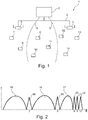
- FIG. 1 For example, as an inventive system 1 for communicating according to a time slot communication method, there is shown an electronic price display system installed in the premises of a retail store. For reasons of clarity, a representation of the premises and their furnishings has been omitted in the figures.
- the system 1 has a server 2, a first and a second communication station 3 and 4 (hereafter referred to as station), and a number of eight radio tags 7 - 14 (hereafter referred to as ESL for electronic shelf label).
- the server is housed in offices and connected to stations 3 and 4 via a wired communication line (LAN) L.
- Stations 3 and 4 are in contact with the ESL 7-14 via radio signals.
- Stations 3 and 4 are mounted in a sales room at different positions on the ceiling.
- the ESL 7 - 14 are mounted on shelves corresponding to products for which price and product information is displayed using the ESL 7 - 14.
- the product information is transmitted from the server 2 to the stations 3, 4 and from there individually communicated to the individual ESL 7-14.
- Each station 3, 4 covers a radio range, with a first radio range limit 5 of the station 3 and a second radio range limit 6 of the station 4 being indicated in regions.
- the radio areas have an overlap area in which the ESL 9-11 are arranged.
- Each station 3 or 4 knows the preferred for the operation of the system 1 radio channels with the channel number 3, 5, 8, 9 and 10. This is in the FIG. 2 represented in the various frequency bands 15 - 22 shown via channel numbers K wind.
- the frequency bands 15, 16 and 17 are available.
- the frequency bands 18, 19, 20 - 22 preferred for the operation of the system 1 correspond to channel numbers 3, 5, 8 - 10 and do not overlap with the WLAN frequency bands 15 - 17.
- the station 3 automatically selected the radio channel with the channel number 3 because this was the first to be checked if he already occupied by another station.
- Station 4 automatically selected the radio channel with channel number 5 because, when testing for free radio channels, it detected that the radio channel with channel number 3 is already occupied and the next free radio channel with channel number 5 was identified.
- the assignment of the radio channels can also be fixed.
- ESL 7 - 14 As soon as the ESL 7 - 14 are inserted in the respective radio area of stations 3 and 4, they detect that radio signals of the relevant stations 3 and 4 exist in one or more radio channels.
- the ESLs 7 and 8 connect to the first station 3.
- the ESLs 12-14 connect to the second station 4.
- Each ESL 9-10 now checks the reception quality of the radio signals received by the respective station 3, 4 and decides for that station 3 or 4 for which the best reception quality has been determined in order to connect to it in the respective radio channel (channel number 3 or 5).
- this decision-making process can also be performed by stations 3 and 4, with the stations checking the quality of each communication with the ESL 9-11 and agreeing with each other on which of them to connect to which of the ESL 9-11 because there are more favorable communication conditions for the respective ESL 9 - 11.
- the decision-making of the assignment between the ESL 9-11 and the stations 3, 4 can, however, also be outsourced to the server 2, since this is in contact with the stations 3, 4.
- radio channels are therefore initially selected (also referred to as "channel scan"), possibly carried out an assessment of the quality of reception on the respective radio channel and then unique hardware addresses of the ESL -14 to the station 3, 4 selected for communication.
- each station 3, 4 knows its respective assigned ESL 7 - 14. This first assignment between station 3, 4 and ESL 7 - 14 is transferred to the server 2.
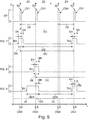
- FIG. 3 is a block diagram of the ESL 7 representative of the system ESL 7 - 14 used in the system, all of which are identical.
- the ESL 7 comprises a radio module 24, a processor 25 for processing data, for controlling operating states and for providing functions, a memory 26 for storing data and programs, and a display 27 realized in energy-saving electronic ink technology to display the product information.
- the radio module 24 is used for radio-based communication with the stations 3 and 4, wherein received data is generated from received radio signals and transferred to the processor 25 or transmitted by the processor 25 transmit data is converted into radio signals.
- the data stored in the memory 26 may be associated with both the processor 25 and the display 27.
- the selected representation does not distinguish which type of memory (ROM, EEPROM, RAM, etc.) it is or how the memory 26 is logically or physically associated with the processor 25 and / or the display 27.
- the selected representation was also on the representation of compounds such as signal and / or data lines between the function blocks 24 - 27 and a representation of the energy storage (in the present case, a battery) omitted.
- image data BD for generating an image by means of the display 27, wherein the image data BD indicate a first image plane of the image with first level data ED1 and a second image plane of the image with second level data ED2, hardware Address data HAD for specifying the hardware address of the ESL, and parameter data PD stored for the parameterization of the time slot communication method. It should be mentioned at this point that also other image levels can be present.
- the hardware address data HAD comprises four bytes B3, B2, B1, B0, where B0 is the least significant byte of the hardware address.
- Both the first and second level data ED1, ED2 represent image information about each pixel.
- image information for both image levels as "transparent", “background” or Defined "background color”. Therefore, the individual image planes can be superimposed pixel by pixel, thus the overall image can be built up by superposition of the image contents to identical coordinates of the pixels of different image planes.
- the images are available in bitmap format, but they can also be in other formats such as JPG, etc.
- a first image plane 28 represented by the first plane data ED1 contains substantially static image information 29 about a product, which static image information is changed only when the ESL 7 is assigned to another product.
- the static image information 29 relates, for example, descriptive text to the product. All other image areas are defined as "transparent”.
- a second image plane 30 represented by the second plane data ED2 essentially contains dynamic image information 31, which changes relatively often compared to static image information, such as daily or even several times a day or even weekly.
- the dynamic image information 31 relates, for example, to the price of the product or also to information on the validity of an offer, such as start date and end date or even times or other conditions that are linked to the offer. All other image areas are defined as "transparent”.
- An overall image 32 represented by the image data BD generated by superimposing each pixel of the first image plane 28 and an exactly corresponding pixel of the second image plane 30 shows both the static and the dynamic image information 29, 32 and the remaining therebetween as " transparent "marked areas.
- the entire image data BD can be received in compressed form all at once, decompressed and stored in the memory 26. This can happen, for example, during a first-time transmission of the overall picture. However, the process is relatively tedious and consequently causes a relatively high energy consumption. As far as the image once exists in the ESL 7, a partial update of the image is more efficient because it can be handled more energy-efficient.
- the ESL 7 can receive, decompress and decompress the image plane (eg the second image plane 30) to be updated separately from the other image plane already stored in the memory 26 (eg the first image plane 28) and store it in the memory 26. Thereafter, the newly created second level data ED2 is internally accessed (switched from one memory page to another memory page) to rebuild the overall image 32.
- the ESL 7 also has a time control stage 33, which may be realized as an independent hardware component or at least partially with the aid of the processor 25. It generates a timebase typical of the ESL and uses this timebase to control the timing (taking and leaving) of the states of the ESL 7. Timing is controlled, e.g. by means of timing parameters inherently known to the timing stage and / or provided by the processor.
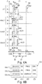
- FIGS. 5 to 8 discussed the time slot communication method used in system 1.
- ESL 7 - 9 assigned to the first stage 3 is discussed, analogous discussions also applying to the ESL 11 - 14 assigned to the second station 4.
- the time t is entered on the abscissa axis.
- their states Z are entered for the respective component of the system 1 considered in the discussion. The diagrams therefore show the temporal state course.
- the uppermost state sequence shows the states of level 3 countersigned by ST.
- a time slot cycle duration DC eg 15 seconds
- N timeslots Z1... ZN eg 256
- identical timeslot duration DS eg approx. 58 milliseconds.
- the stage 3 changes between a transmission state T and an idle state R.
- the transmission state T is always assumed at the beginning of a time slot Z1... ZN and for a synchronization data signal duration DSD (or transmission time DSD of the synchronization signal).
- Data signal SD maintained in order to send with the respective synchronization data signal SD, the respective applicable time slot symbol ZS1, ZS2, ... ZSN.
- the sequence number of the respective time slot Z1 ... ZN is used in the order of occurrence of the time slot Z1 ... ZN.
- the first time slot Z1 is in hexadecimal notation (indicated by "hex") with the time slot symbol Hex 00, the second time slot Z2 with the time slot symbol Hex 01, etc., and the last time slot ZN (in the present example, the two hundred and fifty-sixth time slot Z256 with the time slot symbol Hex FF marked.
- the hardware addresses of the ESL 7 - 9 would be immutable in a real operation of the system 1.
- the ESLs of the system 1 are sometimes assigned different hardware addresses from figure to item or even single or multiple ESLs are not included in the discussion.
- FIG. 5 is the hardware address of the first ESL 7 Hex B2: 00: 01: 00, the second ESL 8 Hex B2: 00: 01: 01 and the third ESL 9 Hex B2: 00: 02: 00.
- the fourth ESL 10 is disregarded.
- FIG. 6 is the hardware address of the first ESL 7 Hex B2: 00: 01: 00, the second ESL 8 Hex B2: 00: 02: 00 and the third ESL 9 Hex B2: 00: 03: 00.
- the fourth ESL 10 is disregarded.
- FIG. 7 is the hardware address of the first ESL 7 Hex B2: 00: 01: 00. The remaining three ESL 8 - 10 are disregarded.
- FIG. 8 is the hardware address of the first ESL 7 Hex B2: 00: 01: 00, the second ESL 8 Hex B2: 00: 01: 01, the third ESL 9 Hex B2: 00: 02: 01 and the fourth ESL 10 Hex B2 : 00: 03: 01.
- the remaining three bytes B1-B3 of the hardware address are used to individually address an ESL 7-10 in the time slot Z1 ... ZN determined for the respective ESL.
- the first ESL 7 is in the synchronous state. It awakens from its sleep state S at a first wake-up time TA1 and, with a relatively short lead-time DV before an expected occurrence of a synchronization data signal SD, changes to its receive active state E, receives the synchronization data signal SD during a receive time period DE first time slot symbol ZS1 (hex 00), by comparing the least significant byte B0 its hardware address (hex 00) with the received time slot symbol ZS1 determines that the first time slot Z1 determined for the first ESL 7 is displayed (match of the bytes to be compared: B0 of the hardware address and first time slot symbol ZS1), the parameters used by the wakeup time control stage 33 retain in the subsequent timeslot cycle for the purpose of defining the new wakeup time, and changes back to sleep state S with a relatively short follow-up time DN to schedule the new sleep-time DW at the new (second) wake-up time TA2 with said lead time VD prior
- the third ESL 9 is in the asynchronous state before a synchronization time TSY, which is indicated by the running parallel to the time axis arrow 34 with a broken line. It awakens to a randomly selected first wake-up time TA1 and changes from its sleep state S into the receive-ready active state E and waits in this state until the next occurrence of the synchronization data signal SD is received, in which case the second time slot symbol ZS2 (FIG. Hex 01) is received.
- the third ESL 9 recognizes from the least significant byte B0 (Hex 00) of its hardware address that the time slot determined in the present time slot cycle is already a thing of the past and consequently the next time slot with the time slot symbol Hex 00 is not to be expected until the next time slot cycle , and calculates that the currently recognized time slot Z2 is one time slot adjacent to its original time slot Z1, hereinafter referred to as the time slot difference.
- the time control stage 33 is now programmed so that the new wakeup time TA2, as with an ESL in synchronous state with said lead time DV, is before the occurrence of the first time slot Z1 of the subsequent time slot cycle.
- the dwell time DSA to be awaited in the sleep state S is calculated as follows: sleep state dwell time DR (in synchronous state) minus time slot duration DS multiplied by time slot difference (in this case, value 1).
- sleep state dwell time DR in synchronous state
- time slot duration DS multiplied by time slot difference (in this case, value 1).
- the third ESL 9 is again in the synchronous state, which is indicated by the arrow 35 with a solid line and changes from the Active state E in the sleep state S, after the dwell time has expired, change DAS back to its active state E at the new wake-up time TA2.
- the synchronization data signal SD transmits a confirmation time for the first ESL 7 by specifying a first idle period DR1, for the second ESL 8 by specifying a second idle period DR2, and for the third ESL 9 by specifying a third idle period DR3.
- the reference point for the three rest periods DR1 - DR3 is always the end of the reception period DE.
- the data structure transmitted with the aid of the synchronization data signal SD at the beginning of the first time slot Z1 is shown in FIG Fig. 6B visualized.
- maximum time periods for responses can also be specified, which result from the sum of the respective rest period DR1-DR3 and the time period for issuing the confirmation data ACD.
- all three ESLs 7-9 detect that they are synchronous because the first time slot symbol Z1 indicates the time slot designated for them (least significant byte B0 of the hardware address is for all three ESLs 7-9 Hex 00).
- the check of the address data AD indicates that each ESL 7-9 is individually addressed (existence of the remaining three bytes B1-B3 of the respective hardware address in the address data AD), the commands specific to the respective ESL 7-9 are decoded and executed immediately, and the individual confirmation data ACD after the expiration of the individual rest periods DR1 ... DR 3 after the end of the reception period DE transmitted to the station 3, which is ready during a station reception period SDE to receive the confirmation data ACD.
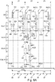
- FIG. 7A the execution of a multiple timeslot command is shown, in which the first ESL 7 breaks down into three data packets DAT1 - DAT3 from the station 3 over three adjacent timeslots Z1 - Z3, total data (eg relating to an entire image to be displayed or just one image plane of the image) receives.
- the first ESL 7 recognizes its synchronous state and that it is addressed individually (addressee Hex B2: 00: 01) with the aid of the synchronization data signal SD, receives and decodes a "DATA_INIT" command, with which it receives the three data packets DAT1 - DAT3 is commanded in said time slots Z1 - Z3, and goes to the sleep state S for a first waiting period DW1 at the end of the reception duration DE, the first waiting period DW1 expiring at the end of the first half of the time slot duration DS.
- the station 3 At the beginning of the second part 37 of the first time slot Z1, the station 3 is in its transmission state T and the first ESL 7 in its ready-to-receive active state E, so that it receives the first data packet DAT1 during a data transmission period DT. Thereafter, it confirms the successful reception by means of partial acknowledgment data ACD1 during a confirmation period DA during which station 3 is also in the receiving state E.
- the confirmation period DA ends before the end of the first time slot Z1.
- the first ESL 7 stays in the sleep state S for a second wait duration DW2, which extends to the end of the first part 36 of the second (subsequent) time slot Z2.
- the station 3 At the beginning of the second part 37 of the second time slot Z2, the station 3 goes into its Send state T and the first ESL 7 in its receive ready active state E, so that it receives the second data packet DAT2 during a data transmission period DT.
- Each successfully transmitted data packet DAT1 - DAT3 is acknowledged using the partial acknowledgment data ACD1 - ACD3.
- the data structure transmitted with the aid of the synchronization data signal SD at the beginning of the first time slot Z1 is shown in FIG Fig. 7B visualized.
- the first ESL 7 recognizes its synchronous state (least significant byte B0 of the hardware address is hex 00) and that it is individually addressed (address data Hex B2: 00: 01) by means of the synchronization data signal SD, receives and decodes a "DATA_INIT Command to receive three data packets DAT1-DAT3 in timeslots Z1-Z3.
- the data structure transmitted with the aid of the synchronization data signal SD at the beginning of the first time slot Z1 is shown in FIG Fig. 8B visualized.
- the data transmission from the station 3 to the first ESL 7 is analogous to the discussion of FIG. 7A ,
- the three remaining ESLs 8-10 recognize at the beginning of the second time slot that they are synchronous because the second time slot symbol Z2 indicates the time slot designated for them (least significant byte B0 of the hardware address is 8 - 10 Hex 01 for all three ESLs).
- the check of the address data AD indicates that each ESL 8-10 is individually addressed (existence of the remaining three bytes B1-B3 of the respective hardware address in the address data AD), the commands destined for the respective ESL 8-10 are decoded (in the present case, three "PING" commands) and immediately executed, and the individual confirmation data ACD is transmitted to the station 3 after a lapse of the individual rest periods DR1 - DR3, as for the FIG. 6A was discussed.
- the data structure transmitted with the aid of the synchronization data signal SD at the beginning of the second time slot Z2 is shown in FIG Fig. 8C visualized.
- the three single-timeslot commands and the multiple timeslot command in the second time slot T2 are treated almost simultaneously with respect to the time unit "time slot", since for the single timeslot commands the first part 36 and the multiple timeslot command are the second part 37 of the second time slot Z2 is reserved for the respectively required data communication.
- the assignment of the respective command type to the parts of the time slot 36, 37 can also be reversed.
Claims (15)
- Balise radio (7-14), qui est conçue afin de communiquer avec une station de communication (3, 4) à l'aide d'un procédé de communication à intervalles de temps,
dans laquelle dans le cadre du procédé de communication à intervalles de temps une pluralité d'intervalles de temps (Z1-ZN) sont fournis en séquences répétitives par cycle d'intervalle de temps à des fins de communication et chaque intervalle de temps (Z1-ZN) est caractérisé par un symbole d'intervalle de temps univoque (ZS1-ZSN), dans laquelle pour l'intervalle de temps actuellement présent (Z1-ZN) au début de l'intervalle de temps respectif (Z1-ZN) un signal de données de synchronisation (SD) présentant le symbole d'intervalle de temps (ZS1-ZSN) est envoyé par la station de communication (3, 4) et
dans laquelle la balise radio (7-14) est configurée pour :+ passer d'un état de veille (S) à un état actif (E) à un point temporel de réveil (TA1), et+ recevoir le signal de données de synchronisation (SD) en l'état actif (E) et+ déterminer son synchronisme avec la station de communication (3, 4) uniquement par la situation de reconnaissance du symbole d'intervalle de temps (ZS1-ZSN), qui apparait à un point temporel escompté par ce dernier, respectivement dans une fenêtre temporelle d'attente et affiche l'intervalle de temps déterminé (Z1-ZN) pour ce dernier, et+ lorsque le symbole d'intervalle de temps reçu (ZS1-ZSN) affiche un intervalle de temps déterminé pour ce dernier (Z1-ZN), définir un nouveau point temporel de réveil (TA2) correspondant à l'apparition suivante de l'intervalle de temps (Z1-ZN) déterminé pour ce dernier dans un cycle d'intervalle de temps suivant le cycle d'intervalle de temps actuellement présent,
et+ après que la balise radio (7-14) a déterminé son synchronisme, passer à nouveau en l'état de veille et y demeurer, jusqu'à ce qu'un réveil et un passage à l'état de veille soit à nouveau effectué en l'état actif vers le nouveau point temporel de réveil dans le le cycle d'intervalle de temps suivant. - Balise radio (7-14) selon la revendication 1, qui, lorsque le symbole d'intervalle de temps reçu (ZS1-ZSN) affiche un intervalle de temps qui n'est pas déterminé pour ce dernier (Z1-ZN), est configurée pour définir un nouveau point de réveil (TA2) correspondant à la survenue suivante de l'intervalle de temps (Z1-ZN) déterminé pour ce dernier dans le cycle d'intervalle de temps actuellement présent, lorsque l'intervalle de temps déterminé pour ce dernier (Z1-ZN) est encore apparu dans le cycle d'intervalle de temps actuellement présent, ou sur le cycle d'intervalle de temps suivant le cycle d'intervalle de temps actuellement présent, lorsque l'intervalle de temps déterminé pour ce dernier (Z1-ZN) n'est plus survenu dans le cycle d'intervalle de temps actuellement présent.
- Balise radio selon une des autres revendications, qui présente un étage de mémoire (26) pour mémoriser les paramètres du procédé de communication à intervalle de temps et qui est configuré pour intervenir sur et prendre en compte ces paramètres à des fins de définition du nouveau point temporel de réveil (TA2).
- Balise radio (7-14) selon une des revendications précédentes, qui présente un étage de mémoire (26) pour mémoriser une représentation du symbole d'intervalle de temps (ZS1-ZSN), qui affiche l'intervalle de temps (Z1-ZN) déterminé pour ce dernier.
- Balise radio (7-14) selon la revendication 4, dans laquelle la représentation du symbole d'intervalle de temps (ZS1-ZSN) est formée à l'aide d'une adresse de matériel de la balise radio (7-14) identifiant de manière univoque la balise radio (7-14) et est programmée de manière non modifiable dans l'étage de mémoire (26).
- Balise radio (7-14) selon la revendication 5, dans laquelle ladite représentation du symbole d'intervalle de temps est réalisée par les bits de plus faible poids ou l'octet de plus faible poids de l'adresse de matériel.
- Balise radio (7-14) selon une des revendications précédentes, dans laquelle la balise radio (7-14) est configurée afin de contrôler qu'un symbole d'intervalle de temps qu'elle connaît concorde avec celui, qui est présent à la réception du signal de données de synchronisation.
- Balise radio (7-14) qui, lorsque le symbole intervalle de temps reçu (ZS1-ZSN) s'affiche à un intervalle de temps déterminé pour ce dernier (Z1-ZN), est configurée pour évaluer le signal de données de synchronisation (SD) en ce qui concerne les données d'adresse (AD) contenues et vérifier si il est adressé individuellement, dans laquelle les données d'adresse (AD) ont été incorporées par la station de communication (3, 4) dans le signal de données de synchronisation (SD) et dans laquelle à l'aide des données d'adresse (AD) une pluralité de balises radio (7-14) par intervalle de temps (Z1-ZN), qui est déterminé pour ladite balise radio (7-14), peuvent être adressées individuellement.
- Balise radio (7-15) selon une des revendications précédentes, qui, lorsque le symbole d'intervalle de temps reçu (ZS1-ZSN) affiche un intervalle de temps déterminé pour ce dernier (Z1-ZN), est configuré pour évaluer le symbole de données de synchronisation (SD) en ce qui concerne les données d'ordre contenues (CD) et pour exécuter l'ordre, dans laquelle les données d'ordre sont incorporées par la station de communication (3, 4) dans le signal de données de synchronisation (SD) et dans laquelle à l'aide des données d'ordre (CD) un ordre peut être transmis à une balise radio (7-14) dans un intervalle de temps (Z1-ZN) qui est déterminé pour ladite balise radio (7-14).
- Balise radio (7-14) selon la revendication 9, considérée en dépendance de la revendication 8, dans laquelle la balise radio (7-14) est configurée afin d'évaluer les données d'ordre (CD) et exécuter l'ordre, quand elle est adressée individuellement à l'aide des données d'adresse (AD) .
- Balise radio (7-14) selon la revendication 9 ou 10, dans laquelle la balise radio (7-14) est configurée pour exécuter un ordre d'intervalle de temps simple et mettre fin à l'ordre exécuté en l'espace d'un intervalle de temps unique (Z1-ZN), dans lequel l'ordre a été reçu.
- Balise radio (7-14) selon la revendication 11, dans laquelle la balise radio (7-14), lorsque l'ordre exécuté prend fin, est configurée pour générer des données de confirmation (ACD) et pour émettre les données de confirmation (ACD) dans chaque intervalle de temps (Z1-ZN), dans lequel l'ordre a été reçu.
- Balise radio (7-14) selon la revendication 12, dans laquelle la balise radio (7-14) est configurée pour émettre les données de confirmation (ACD) dans la première partie (36) de l'intervalle de temps (Z1-ZN), qui est localisé temporellement à la suite du signal de données de synchronisation (SD) et n'a pas d'incidence sur une deuxième partie consécutive (37) de l'intervalle de temps (Z1-ZN) avant la survenue du signal de données de synchronisation (SD) de l'intervalle de temps suivant (Z1-ZN).
- Balise radio (7-14) selon la revendication 12 ou 13, dans laquelle la balise radio (7-14) est configurée afin de, à côté de son adresse propre, lorsque plusieurs balises radio (7-14) sont adressées à l'aide des données d'adresse (AD), évaluer également chacune d'une ou des autres balises radio adressées (7-14) et émettre ses données de confirmation (ACD) en l'espace d'une fenêtre temporelle prévue pour l'émission des données de confirmation (ACD) à chaque point temporel, qui correspond à la séquence déterminée pour ce dernier par les adresses déterminées dans le groupe des balises radio adressées (7-14).
- Balise radio (7-14) selon une des revendications précédentes, qui présente une unité d'affichage (27), qui sert à afficher une information de produit ou de prix.
Priority Applications (1)
| Application Number | Priority Date | Filing Date | Title |
|---|---|---|---|
| EP18201448.0A EP3467756B1 (fr) | 2014-02-20 | 2014-02-20 | Étiquette rfid pour la communication par tranche de temps |
Applications Claiming Priority (3)
| Application Number | Priority Date | Filing Date | Title |
|---|---|---|---|
| EP18201448.0A EP3467756B1 (fr) | 2014-02-20 | 2014-02-20 | Étiquette rfid pour la communication par tranche de temps |
| EP14707354.8A EP3108429B1 (fr) | 2014-02-20 | 2014-02-20 | Système de communication par créneau temporel |
| PCT/EP2014/053376 WO2015124197A1 (fr) | 2014-02-20 | 2014-02-20 | Système de communication par créneau temporel |
Related Parent Applications (1)
| Application Number | Title | Priority Date | Filing Date |
|---|---|---|---|
| EP14707354.8A Division EP3108429B1 (fr) | 2014-02-20 | 2014-02-20 | Système de communication par créneau temporel |
Publications (2)
| Publication Number | Publication Date |
|---|---|
| EP3467756A1 EP3467756A1 (fr) | 2019-04-10 |
| EP3467756B1 true EP3467756B1 (fr) | 2019-12-11 |
Family
ID=50190417
Family Applications (6)
| Application Number | Title | Priority Date | Filing Date |
|---|---|---|---|
| EP18201448.0A Active EP3467756B1 (fr) | 2014-02-20 | 2014-02-20 | Étiquette rfid pour la communication par tranche de temps |
| EP19216347.5A Pending EP3657424A1 (fr) | 2014-02-20 | 2014-02-20 | Système de communication par intervalles de temps |
| EP18193356.5A Active EP3444768B1 (fr) | 2014-02-20 | 2014-02-20 | Système de communication par créneau temporel |
| EP14707354.8A Active EP3108429B1 (fr) | 2014-02-20 | 2014-02-20 | Système de communication par créneau temporel |
| EP18193354.0A Active EP3444767B1 (fr) | 2014-02-20 | 2014-02-20 | Système de communication par créneau temporel |
| EP18193360.7A Active EP3444769B1 (fr) | 2014-02-20 | 2014-02-20 | Système de communication par créneau temporel |
Family Applications After (5)
| Application Number | Title | Priority Date | Filing Date |
|---|---|---|---|
| EP19216347.5A Pending EP3657424A1 (fr) | 2014-02-20 | 2014-02-20 | Système de communication par intervalles de temps |
| EP18193356.5A Active EP3444768B1 (fr) | 2014-02-20 | 2014-02-20 | Système de communication par créneau temporel |
| EP14707354.8A Active EP3108429B1 (fr) | 2014-02-20 | 2014-02-20 | Système de communication par créneau temporel |
| EP18193354.0A Active EP3444767B1 (fr) | 2014-02-20 | 2014-02-20 | Système de communication par créneau temporel |
| EP18193360.7A Active EP3444769B1 (fr) | 2014-02-20 | 2014-02-20 | Système de communication par créneau temporel |
Country Status (14)
| Country | Link |
|---|---|
| US (1) | US9792468B2 (fr) |
| EP (6) | EP3467756B1 (fr) |
| JP (1) | JP6228687B2 (fr) |
| AU (1) | AU2014383584B2 (fr) |
| BR (1) | BR112016018902B1 (fr) |
| CA (1) | CA2939471C (fr) |
| DK (1) | DK3108429T3 (fr) |
| ES (1) | ES2705874T3 (fr) |
| MX (1) | MX358729B (fr) |
| RU (1) | RU2698915C2 (fr) |
| SG (1) | SG11201606588UA (fr) |
| SI (1) | SI3108429T1 (fr) |
| WO (1) | WO2015124197A1 (fr) |
| ZA (1) | ZA201605314B (fr) |
Families Citing this family (25)
| Publication number | Priority date | Publication date | Assignee | Title |
|---|---|---|---|---|
| WO2015124197A1 (fr) * | 2014-02-20 | 2015-08-27 | Imagotag Gmbh | Système de communication par créneau temporel |
| EP3770818B1 (fr) * | 2015-12-10 | 2022-10-05 | SES-Imagotag GmbH | Dispositif d'affichage permettant d'afficher les prix et/ou les informations sur le produit |
| US10068113B2 (en) * | 2016-08-16 | 2018-09-04 | Ses-Imagotag Gmbh | Time slot communication system |
| US10045296B2 (en) * | 2016-12-20 | 2018-08-07 | Intel IP Corporation | Method and apparatus to controlling sleep time for Bluetooth device and Bluetooth enabled device |
| US10510042B2 (en) * | 2017-09-29 | 2019-12-17 | Sensormatic Electronics, LLC | Systems and methods for determining inventory using time-slotted tag communications |
| JP2020025400A (ja) * | 2018-08-07 | 2020-02-13 | 株式会社東芝 | 無線送電装置及び無線送電方法 |
| JP7254889B2 (ja) * | 2018-08-07 | 2023-04-10 | 株式会社東芝 | 無線送電装置及び無線送電方法 |
| JP6682666B2 (ja) * | 2019-01-08 | 2020-04-15 | エスエーエス−イマーゴタグ・ゲゼルシャフト・ミト・ベシュレンクテル・ハフツング | タイムスロット通信システム |
| CN109587778B (zh) * | 2019-01-18 | 2022-02-08 | 重庆物奇科技有限公司 | 用于电子价签的通信方法 |
| US11948041B2 (en) | 2019-06-14 | 2024-04-02 | Ses-Imagotag Gmbh | Electronic shelf labelling system with a power supply |
| EP3984254A1 (fr) | 2019-06-14 | 2022-04-20 | SES-Imagotag GmbH | Procédé de localisation d'une étiquette électronique pour rayonnage |
| CN113994723A (zh) | 2019-06-14 | 2022-01-28 | 赛斯-伊玛格标签有限责任公司 | 具有货架轨道子系统的电子货架标签系统 |
| US20220335862A1 (en) | 2019-08-19 | 2022-10-20 | Ses-Imagotag Gmbh | Electronic shelf-label system with a contact-free shelf-label power and/or data supply |
| CN114730531A (zh) | 2019-11-22 | 2022-07-08 | 赛斯-伊玛格标签有限责任公司 | 用电池组供电的电子标签 |
| WO2021129934A1 (fr) | 2019-12-23 | 2021-07-01 | Ses-Imagotag Gmbh | Étiquette électronique de rayonnage à déclenchement d'action |
| CN114787765A (zh) | 2019-12-23 | 2022-07-22 | 赛斯-伊玛格标签有限责任公司 | 具有货架导轨子系统的电子货架标签系统 |
| EP4245054A1 (fr) * | 2020-11-12 | 2023-09-20 | SES-Imagotag GmbH | Procédé pour l'attribution de canal radio dans un système d'affichage électronique |
| CN116888654A (zh) | 2020-12-23 | 2023-10-13 | 赛斯-伊玛格标签有限责任公司 | 用于将显示单元固定或紧固在承载装置处的固定元件 |
| KR20230153395A (ko) | 2021-03-09 | 2023-11-06 | 에스에에스-이마고탁 게엠베하 | 버스 시스템 및 버스 시스템을 포함하는 지지 장치 |
| EP4323985A1 (fr) | 2021-04-13 | 2024-02-21 | SES-Imagotag GmbH | Dispositif de support pour supporter un dispositif électronique à l'intérieur d'une zone de réception pour le dispositif de support |
| WO2023274554A1 (fr) | 2021-07-02 | 2023-01-05 | Ses-Imagotag Gmbh | Procédé de guidage d'une personne vers des produits |
| AU2021469140A1 (en) | 2021-10-14 | 2024-05-02 | Vusiongroup Sa | Method for logically linking an electronic display unit to a product |
| WO2023110139A1 (fr) | 2021-12-18 | 2023-06-22 | Ses-Imagotag Gmbh | Dispositif d'aide aux personnes malvoyantes ou aveugles pendant les courses |
| WO2023117116A1 (fr) | 2021-12-23 | 2023-06-29 | Pdi Digital Gmbh | Dispositif d'affichage électronique doté d'un capteur d'accélération |
| WO2024074216A1 (fr) | 2022-10-07 | 2024-04-11 | Ses-Imagotag Sa | Procédé mis en œuvre par ordinateur pour déclencher une fonction |
Family Cites Families (13)
| Publication number | Priority date | Publication date | Assignee | Title |
|---|---|---|---|---|
| DE4439074C2 (de) | 1994-11-02 | 1998-09-17 | Pricer Ab | Anlage zur elektronischen Preisanzeige |
| US6044359A (en) * | 1997-11-13 | 2000-03-28 | Ncr Corporation | Method of minimizing power consumption within an electronic price label |
| JP3300280B2 (ja) * | 1998-04-23 | 2002-07-08 | インターナショナル・ビジネス・マシーンズ・コーポレーション | 画像合成処理装置およびその方法 |
| ES2345881T3 (es) * | 2002-02-28 | 2010-10-05 | Pricer Ab | Sistema y metodo para actualizar las pantallas de etiquetas electronicas. |
| KR100771466B1 (ko) * | 2006-04-27 | 2007-10-30 | 김정선 | 재난 구조용 GPS주파수가 130 dBm 펄스 폭에 형성된5 ㎓ 밀리미터파 주파수대역을 이용한 초 광대역주파수확장변조 복합무선통신시스템 |
| JP2008168057A (ja) * | 2007-01-15 | 2008-07-24 | Ishida Co Ltd | 電子棚札及び電子棚札システム |
| GB0812770D0 (en) | 2008-07-11 | 2008-08-20 | Zbd Displays Ltd | A display system |
| JP5125972B2 (ja) * | 2008-10-09 | 2013-01-23 | カシオ計算機株式会社 | 無線端末装置、無線中継装置及びプログラム |
| US8525642B2 (en) * | 2009-05-08 | 2013-09-03 | Icontrol, Inc. | Methods and systems for communication protocol for distributed asset management |
| JP2011171993A (ja) * | 2010-02-18 | 2011-09-01 | Seiko Instruments Inc | 情報処理装置、及び無線端末 |
| US20110316676A1 (en) | 2010-06-23 | 2011-12-29 | Savi Technology | Apparatus and method for managing power-constrained wireless devices |
| TWM418349U (en) * | 2011-06-24 | 2011-12-11 | Ceramicro Technology Corp | Electronic label time-division control system |
| WO2015124197A1 (fr) * | 2014-02-20 | 2015-08-27 | Imagotag Gmbh | Système de communication par créneau temporel |
-
2014
- 2014-02-20 WO PCT/EP2014/053376 patent/WO2015124197A1/fr active Application Filing
- 2014-02-20 SG SG11201606588UA patent/SG11201606588UA/en unknown
- 2014-02-20 MX MX2016010597A patent/MX358729B/es active IP Right Grant
- 2014-02-20 EP EP18201448.0A patent/EP3467756B1/fr active Active
- 2014-02-20 ES ES14707354T patent/ES2705874T3/es active Active
- 2014-02-20 BR BR112016018902-7A patent/BR112016018902B1/pt active IP Right Grant
- 2014-02-20 EP EP19216347.5A patent/EP3657424A1/fr active Pending
- 2014-02-20 DK DK14707354.8T patent/DK3108429T3/en active
- 2014-02-20 JP JP2016551783A patent/JP6228687B2/ja active Active
- 2014-02-20 US US15/119,259 patent/US9792468B2/en active Active
- 2014-02-20 EP EP18193356.5A patent/EP3444768B1/fr active Active
- 2014-02-20 EP EP14707354.8A patent/EP3108429B1/fr active Active
- 2014-02-20 SI SI201431040T patent/SI3108429T1/sl unknown
- 2014-02-20 EP EP18193354.0A patent/EP3444767B1/fr active Active
- 2014-02-20 RU RU2016133391A patent/RU2698915C2/ru active
- 2014-02-20 AU AU2014383584A patent/AU2014383584B2/en active Active
- 2014-02-20 CA CA2939471A patent/CA2939471C/fr active Active
- 2014-02-20 EP EP18193360.7A patent/EP3444769B1/fr active Active
-
2016
- 2016-08-01 ZA ZA2016/05314A patent/ZA201605314B/en unknown
Non-Patent Citations (1)
| Title |
|---|
| None * |
Also Published As
| Publication number | Publication date |
|---|---|
| EP3444767B1 (fr) | 2021-05-12 |
| ES2705874T3 (es) | 2019-03-26 |
| EP3444768A1 (fr) | 2019-02-20 |
| AU2014383584B2 (en) | 2018-05-10 |
| CA2939471A1 (fr) | 2015-08-27 |
| CA2939471C (fr) | 2018-10-09 |
| JP2017507598A (ja) | 2017-03-16 |
| EP3444767A1 (fr) | 2019-02-20 |
| MX2016010597A (es) | 2017-05-04 |
| RU2698915C2 (ru) | 2019-09-02 |
| ZA201605314B (en) | 2022-02-23 |
| AU2014383584A1 (en) | 2016-09-29 |
| EP3444768B1 (fr) | 2021-05-12 |
| RU2016133391A (ru) | 2018-02-20 |
| BR112016018902B1 (pt) | 2021-01-26 |
| SG11201606588UA (en) | 2016-09-29 |
| EP3444769A1 (fr) | 2019-02-20 |
| JP6228687B2 (ja) | 2017-11-08 |
| EP3444769B1 (fr) | 2022-06-15 |
| US9792468B2 (en) | 2017-10-17 |
| EP3108429B1 (fr) | 2018-10-31 |
| EP3108429A1 (fr) | 2016-12-28 |
| SI3108429T1 (sl) | 2019-03-29 |
| WO2015124197A1 (fr) | 2015-08-27 |
| EP3467756A1 (fr) | 2019-04-10 |
| US20170011238A1 (en) | 2017-01-12 |
| MX358729B (es) | 2018-09-03 |
| DK3108429T3 (en) | 2019-02-18 |
| EP3657424A1 (fr) | 2020-05-27 |
Similar Documents
| Publication | Publication Date | Title |
|---|---|---|
| EP3467756B1 (fr) | Étiquette rfid pour la communication par tranche de temps | |
| EP3387585B1 (fr) | Dispositif d'affichage comprenant un étage de traitement contrôlable | |
| EP2202599B1 (fr) | Commande industrielle en réseau et procédé d'échange du mode de fonctionnement d'une telle commande industrielle | |
| EP3143422B1 (fr) | Procédé de localisation d'une étiquette rfid | |
| EP3198967B1 (fr) | Station de radiocommunication de base et système avec ladite station de radiocommunication de base | |
| DE102010028665A1 (de) | Verfahren zum Wechseln eines Betriebszustands mindestens einer Vorrichtung | |
| WO2009059436A1 (fr) | Réseau rfid et procédé de fonctionnement du réseau rfid | |
| DE112016006338B4 (de) | Kommunikationsvorrichtung, Kommunikationssystem und Kommunikationsverfahren | |
| WO2020083512A1 (fr) | Station de base radio pour la communication radio combinée | |
| WO2022100840A1 (fr) | Procédé pour l'attribution de canal radio dans un système d'affichage électronique | |
| DE102009051546A1 (de) | Vorrichtung mit einer Vielzahl von Steuergeräten für Fluid-Regelkreise | |
| AT408819B (de) | Regel- und/oder steuervorrichtung für die objektleittechnik | |
| WO2016079091A1 (fr) | Procédé de fonctionnement d'un premier et d'au moins un deuxième appareil de terrain | |
| DE102009013576A1 (de) | Verfahren zum Übertragen von Daten in einem drahtlosen Kommunikationsnetzwerk, Knoten für ein drahtloses Kommunikationsnetzwerk und ein Kommunikationsnetzwerk | |
| EP2156621A1 (fr) | Procédé pour faire fonctionner un système de communication, n ud de coordination d'un système de communication et système de communication | |
| WO2020173625A1 (fr) | Procédé d'exploitation d'un réseau sans fil d'appareils de terrain | |
| DE102012002803A1 (de) | Verfahren zur Übertragung von Daten an einen Empfänger |
Legal Events
| Date | Code | Title | Description |
|---|---|---|---|
| PUAI | Public reference made under article 153(3) epc to a published international application that has entered the european phase |
Free format text: ORIGINAL CODE: 0009012 |
|
| STAA | Information on the status of an ep patent application or granted ep patent |
Free format text: STATUS: THE APPLICATION HAS BEEN PUBLISHED |
|
| AC | Divisional application: reference to earlier application |
Ref document number: 3108429 Country of ref document: EP Kind code of ref document: P |
|
| AK | Designated contracting states |
Kind code of ref document: A1 Designated state(s): AL AT BE BG CH CY CZ DE DK EE ES FI FR GB GR HR HU IE IS IT LI LT LU LV MC MK MT NL NO PL PT RO RS SE SI SK SM TR |
|
| STAA | Information on the status of an ep patent application or granted ep patent |
Free format text: STATUS: REQUEST FOR EXAMINATION WAS MADE |
|
| 17P | Request for examination filed |
Effective date: 20190412 |
|
| RBV | Designated contracting states (corrected) |
Designated state(s): AL AT BE BG CH CY CZ DE DK EE ES FI FR GB GR HR HU IE IS IT LI LT LU LV MC MK MT NL NO PL PT RO RS SE SI SK SM TR |
|
| RAP1 | Party data changed (applicant data changed or rights of an application transferred) |
Owner name: SES-IMAGOTAG GMBH |
|
| RIC1 | Information provided on ipc code assigned before grant |
Ipc: G06K 7/10 20060101ALI20190807BHEP Ipc: G06Q 30/02 20120101AFI20190807BHEP |
|
| GRAP | Despatch of communication of intention to grant a patent |
Free format text: ORIGINAL CODE: EPIDOSNIGR1 |
|
| STAA | Information on the status of an ep patent application or granted ep patent |
Free format text: STATUS: GRANT OF PATENT IS INTENDED |
|
| INTG | Intention to grant announced |
Effective date: 20190917 |
|
| GRAS | Grant fee paid |
Free format text: ORIGINAL CODE: EPIDOSNIGR3 |
|
| GRAA | (expected) grant |
Free format text: ORIGINAL CODE: 0009210 |
|
| STAA | Information on the status of an ep patent application or granted ep patent |
Free format text: STATUS: THE PATENT HAS BEEN GRANTED |
|
| RIN1 | Information on inventor provided before grant (corrected) |
Inventor name: HECHENBLAICKNER, ANDREAS Inventor name: ROESSL, ANDREAS Inventor name: FRIESSNEGG, CHRISTIAN |
|
| AC | Divisional application: reference to earlier application |
Ref document number: 3108429 Country of ref document: EP Kind code of ref document: P |
|
| AK | Designated contracting states |
Kind code of ref document: B1 Designated state(s): AL AT BE BG CH CY CZ DE DK EE ES FI FR GB GR HR HU IE IS IT LI LT LU LV MC MK MT NL NO PL PT RO RS SE SI SK SM TR |
|
| REG | Reference to a national code |
Ref country code: GB Ref legal event code: FG4D Free format text: NOT ENGLISH |
|
| REG | Reference to a national code |
Ref country code: CH Ref legal event code: EP |
|
| REG | Reference to a national code |
Ref country code: AT Ref legal event code: REF Ref document number: 1212928 Country of ref document: AT Kind code of ref document: T Effective date: 20191215 |
|
| REG | Reference to a national code |
Ref country code: DE Ref legal event code: R096 Ref document number: 502014013257 Country of ref document: DE |
|
| REG | Reference to a national code |
Ref country code: IE Ref legal event code: FG4D Free format text: LANGUAGE OF EP DOCUMENT: GERMAN |
|
| REG | Reference to a national code |
Ref country code: SE Ref legal event code: TRGR |
|
| REG | Reference to a national code |
Ref country code: NL Ref legal event code: MP Effective date: 20191211 |
|
| REG | Reference to a national code |
Ref country code: LT Ref legal event code: MG4D |
|
| PG25 | Lapsed in a contracting state [announced via postgrant information from national office to epo] |
Ref country code: FI Free format text: LAPSE BECAUSE OF FAILURE TO SUBMIT A TRANSLATION OF THE DESCRIPTION OR TO PAY THE FEE WITHIN THE PRESCRIBED TIME-LIMIT Effective date: 20191211 Ref country code: BG Free format text: LAPSE BECAUSE OF FAILURE TO SUBMIT A TRANSLATION OF THE DESCRIPTION OR TO PAY THE FEE WITHIN THE PRESCRIBED TIME-LIMIT Effective date: 20200311 Ref country code: LV Free format text: LAPSE BECAUSE OF FAILURE TO SUBMIT A TRANSLATION OF THE DESCRIPTION OR TO PAY THE FEE WITHIN THE PRESCRIBED TIME-LIMIT Effective date: 20191211 Ref country code: NO Free format text: LAPSE BECAUSE OF FAILURE TO SUBMIT A TRANSLATION OF THE DESCRIPTION OR TO PAY THE FEE WITHIN THE PRESCRIBED TIME-LIMIT Effective date: 20200311 Ref country code: GR Free format text: LAPSE BECAUSE OF FAILURE TO SUBMIT A TRANSLATION OF THE DESCRIPTION OR TO PAY THE FEE WITHIN THE PRESCRIBED TIME-LIMIT Effective date: 20200312 Ref country code: LT Free format text: LAPSE BECAUSE OF FAILURE TO SUBMIT A TRANSLATION OF THE DESCRIPTION OR TO PAY THE FEE WITHIN THE PRESCRIBED TIME-LIMIT Effective date: 20191211 |
|
| PG25 | Lapsed in a contracting state [announced via postgrant information from national office to epo] |
Ref country code: HR Free format text: LAPSE BECAUSE OF FAILURE TO SUBMIT A TRANSLATION OF THE DESCRIPTION OR TO PAY THE FEE WITHIN THE PRESCRIBED TIME-LIMIT Effective date: 20191211 Ref country code: RS Free format text: LAPSE BECAUSE OF FAILURE TO SUBMIT A TRANSLATION OF THE DESCRIPTION OR TO PAY THE FEE WITHIN THE PRESCRIBED TIME-LIMIT Effective date: 20191211 |
|
| PG25 | Lapsed in a contracting state [announced via postgrant information from national office to epo] |
Ref country code: AL Free format text: LAPSE BECAUSE OF FAILURE TO SUBMIT A TRANSLATION OF THE DESCRIPTION OR TO PAY THE FEE WITHIN THE PRESCRIBED TIME-LIMIT Effective date: 20191211 |
|
| PG25 | Lapsed in a contracting state [announced via postgrant information from national office to epo] |
Ref country code: EE Free format text: LAPSE BECAUSE OF FAILURE TO SUBMIT A TRANSLATION OF THE DESCRIPTION OR TO PAY THE FEE WITHIN THE PRESCRIBED TIME-LIMIT Effective date: 20191211 Ref country code: ES Free format text: LAPSE BECAUSE OF FAILURE TO SUBMIT A TRANSLATION OF THE DESCRIPTION OR TO PAY THE FEE WITHIN THE PRESCRIBED TIME-LIMIT Effective date: 20191211 Ref country code: NL Free format text: LAPSE BECAUSE OF FAILURE TO SUBMIT A TRANSLATION OF THE DESCRIPTION OR TO PAY THE FEE WITHIN THE PRESCRIBED TIME-LIMIT Effective date: 20191211 Ref country code: RO Free format text: LAPSE BECAUSE OF FAILURE TO SUBMIT A TRANSLATION OF THE DESCRIPTION OR TO PAY THE FEE WITHIN THE PRESCRIBED TIME-LIMIT Effective date: 20191211 Ref country code: CZ Free format text: LAPSE BECAUSE OF FAILURE TO SUBMIT A TRANSLATION OF THE DESCRIPTION OR TO PAY THE FEE WITHIN THE PRESCRIBED TIME-LIMIT Effective date: 20191211 Ref country code: PT Free format text: LAPSE BECAUSE OF FAILURE TO SUBMIT A TRANSLATION OF THE DESCRIPTION OR TO PAY THE FEE WITHIN THE PRESCRIBED TIME-LIMIT Effective date: 20200506 |
|
| PG25 | Lapsed in a contracting state [announced via postgrant information from national office to epo] |
Ref country code: SM Free format text: LAPSE BECAUSE OF FAILURE TO SUBMIT A TRANSLATION OF THE DESCRIPTION OR TO PAY THE FEE WITHIN THE PRESCRIBED TIME-LIMIT Effective date: 20191211 Ref country code: IS Free format text: LAPSE BECAUSE OF FAILURE TO SUBMIT A TRANSLATION OF THE DESCRIPTION OR TO PAY THE FEE WITHIN THE PRESCRIBED TIME-LIMIT Effective date: 20200411 Ref country code: SK Free format text: LAPSE BECAUSE OF FAILURE TO SUBMIT A TRANSLATION OF THE DESCRIPTION OR TO PAY THE FEE WITHIN THE PRESCRIBED TIME-LIMIT Effective date: 20191211 |
|
| REG | Reference to a national code |
Ref country code: DE Ref legal event code: R097 Ref document number: 502014013257 Country of ref document: DE |
|
| REG | Reference to a national code |
Ref country code: CH Ref legal event code: PL |
|
| PLBE | No opposition filed within time limit |
Free format text: ORIGINAL CODE: 0009261 |
|
| STAA | Information on the status of an ep patent application or granted ep patent |
Free format text: STATUS: NO OPPOSITION FILED WITHIN TIME LIMIT |
|
| REG | Reference to a national code |
Ref country code: BE Ref legal event code: MM Effective date: 20200229 |
|
| PG25 | Lapsed in a contracting state [announced via postgrant information from national office to epo] |
Ref country code: DK Free format text: LAPSE BECAUSE OF FAILURE TO SUBMIT A TRANSLATION OF THE DESCRIPTION OR TO PAY THE FEE WITHIN THE PRESCRIBED TIME-LIMIT Effective date: 20191211 Ref country code: LU Free format text: LAPSE BECAUSE OF NON-PAYMENT OF DUE FEES Effective date: 20200220 Ref country code: MC Free format text: LAPSE BECAUSE OF FAILURE TO SUBMIT A TRANSLATION OF THE DESCRIPTION OR TO PAY THE FEE WITHIN THE PRESCRIBED TIME-LIMIT Effective date: 20191211 |
|
| 26N | No opposition filed |
Effective date: 20200914 |
|
| PG25 | Lapsed in a contracting state [announced via postgrant information from national office to epo] |
Ref country code: LI Free format text: LAPSE BECAUSE OF NON-PAYMENT OF DUE FEES Effective date: 20200229 Ref country code: CH Free format text: LAPSE BECAUSE OF NON-PAYMENT OF DUE FEES Effective date: 20200229 |
|
| PG25 | Lapsed in a contracting state [announced via postgrant information from national office to epo] |
Ref country code: IT Free format text: LAPSE BECAUSE OF FAILURE TO SUBMIT A TRANSLATION OF THE DESCRIPTION OR TO PAY THE FEE WITHIN THE PRESCRIBED TIME-LIMIT Effective date: 20191211 |
|
| PG25 | Lapsed in a contracting state [announced via postgrant information from national office to epo] |
Ref country code: PL Free format text: LAPSE BECAUSE OF FAILURE TO SUBMIT A TRANSLATION OF THE DESCRIPTION OR TO PAY THE FEE WITHIN THE PRESCRIBED TIME-LIMIT Effective date: 20191211 Ref country code: SI Free format text: LAPSE BECAUSE OF FAILURE TO SUBMIT A TRANSLATION OF THE DESCRIPTION OR TO PAY THE FEE WITHIN THE PRESCRIBED TIME-LIMIT Effective date: 20191211 Ref country code: BE Free format text: LAPSE BECAUSE OF NON-PAYMENT OF DUE FEES Effective date: 20200229 |
|
| PG25 | Lapsed in a contracting state [announced via postgrant information from national office to epo] |
Ref country code: TR Free format text: LAPSE BECAUSE OF FAILURE TO SUBMIT A TRANSLATION OF THE DESCRIPTION OR TO PAY THE FEE WITHIN THE PRESCRIBED TIME-LIMIT Effective date: 20191211 Ref country code: MT Free format text: LAPSE BECAUSE OF FAILURE TO SUBMIT A TRANSLATION OF THE DESCRIPTION OR TO PAY THE FEE WITHIN THE PRESCRIBED TIME-LIMIT Effective date: 20191211 Ref country code: CY Free format text: LAPSE BECAUSE OF FAILURE TO SUBMIT A TRANSLATION OF THE DESCRIPTION OR TO PAY THE FEE WITHIN THE PRESCRIBED TIME-LIMIT Effective date: 20191211 |
|
| PG25 | Lapsed in a contracting state [announced via postgrant information from national office to epo] |
Ref country code: MK Free format text: LAPSE BECAUSE OF FAILURE TO SUBMIT A TRANSLATION OF THE DESCRIPTION OR TO PAY THE FEE WITHIN THE PRESCRIBED TIME-LIMIT Effective date: 20191211 |
|
| PGFP | Annual fee paid to national office [announced via postgrant information from national office to epo] |
Ref country code: IE Payment date: 20230217 Year of fee payment: 10 Ref country code: FR Payment date: 20230221 Year of fee payment: 10 Ref country code: AT Payment date: 20230217 Year of fee payment: 10 |
|
| PGFP | Annual fee paid to national office [announced via postgrant information from national office to epo] |
Ref country code: SE Payment date: 20230216 Year of fee payment: 10 Ref country code: GB Payment date: 20230221 Year of fee payment: 10 Ref country code: DE Payment date: 20230216 Year of fee payment: 10 |
|
| P01 | Opt-out of the competence of the unified patent court (upc) registered |
Effective date: 20230428 |
|
| PGFP | Annual fee paid to national office [announced via postgrant information from national office to epo] |
Ref country code: IE Payment date: 20240220 Year of fee payment: 11 |
|
| PGFP | Annual fee paid to national office [announced via postgrant information from national office to epo] |
Ref country code: AT Payment date: 20240220 Year of fee payment: 11 |
|
| PGFP | Annual fee paid to national office [announced via postgrant information from national office to epo] |
Ref country code: DE Payment date: 20240219 Year of fee payment: 11 Ref country code: GB Payment date: 20240219 Year of fee payment: 11 |