EP3467608B1 - Stability and command augmentation system for an aircraft - Google Patents
Stability and command augmentation system for an aircraft Download PDFInfo
- Publication number
- EP3467608B1 EP3467608B1 EP17194901.9A EP17194901A EP3467608B1 EP 3467608 B1 EP3467608 B1 EP 3467608B1 EP 17194901 A EP17194901 A EP 17194901A EP 3467608 B1 EP3467608 B1 EP 3467608B1
- Authority
- EP
- European Patent Office
- Prior art keywords
- piston
- force
- command
- valve
- rod
- Prior art date
- Legal status (The legal status is an assumption and is not a legal conclusion. Google has not performed a legal analysis and makes no representation as to the accuracy of the status listed.)
- Active
Links
- 230000003416 augmentation Effects 0.000 title claims description 11
- RZVHIXYEVGDQDX-UHFFFAOYSA-N 9,10-anthraquinone Chemical compound C1=CC=C2C(=O)C3=CC=CC=C3C(=O)C2=C1 RZVHIXYEVGDQDX-UHFFFAOYSA-N 0.000 claims description 40
- 238000000034 method Methods 0.000 claims description 7
- 230000006641 stabilisation Effects 0.000 claims description 3
- 238000011105 stabilization Methods 0.000 claims description 3
- 244000182067 Fraxinus ornus Species 0.000 claims 1
- 238000013519 translation Methods 0.000 description 14
- 230000014616 translation Effects 0.000 description 14
- 230000007935 neutral effect Effects 0.000 description 6
- 125000004122 cyclic group Chemical group 0.000 description 3
- 230000005540 biological transmission Effects 0.000 description 2
- 238000012423 maintenance Methods 0.000 description 2
- 238000004519 manufacturing process Methods 0.000 description 2
- 230000000087 stabilizing effect Effects 0.000 description 2
- 238000012546 transfer Methods 0.000 description 2
- 238000010586 diagram Methods 0.000 description 1
- 238000012986 modification Methods 0.000 description 1
- 230000004048 modification Effects 0.000 description 1
- 230000010355 oscillation Effects 0.000 description 1
- 230000036316 preload Effects 0.000 description 1
- 230000001681 protective effect Effects 0.000 description 1
Images


Classifications
-
- B—PERFORMING OPERATIONS; TRANSPORTING
- B64—AIRCRAFT; AVIATION; COSMONAUTICS
- B64C—AEROPLANES; HELICOPTERS
- B64C13/00—Control systems or transmitting systems for actuating flying-control surfaces, lift-increasing flaps, air brakes, or spoilers
-
- G—PHYSICS
- G05—CONTROLLING; REGULATING
- G05D—SYSTEMS FOR CONTROLLING OR REGULATING NON-ELECTRIC VARIABLES
- G05D1/00—Control of position, course or altitude of land, water, air, or space vehicles, e.g. automatic pilot
- G05D1/08—Control of attitude, i.e. control of roll, pitch, or yaw
- G05D1/0808—Control of attitude, i.e. control of roll, pitch, or yaw specially adapted for aircraft
- G05D1/0816—Control of attitude, i.e. control of roll, pitch, or yaw specially adapted for aircraft to ensure stability
-
- F—MECHANICAL ENGINEERING; LIGHTING; HEATING; WEAPONS; BLASTING
- F15—FLUID-PRESSURE ACTUATORS; HYDRAULICS OR PNEUMATICS IN GENERAL
- F15B—SYSTEMS ACTING BY MEANS OF FLUIDS IN GENERAL; FLUID-PRESSURE ACTUATORS, e.g. SERVOMOTORS; DETAILS OF FLUID-PRESSURE SYSTEMS, NOT OTHERWISE PROVIDED FOR
- F15B18/00—Parallel arrangements of independent servomotor systems
-
- B—PERFORMING OPERATIONS; TRANSPORTING
- B64—AIRCRAFT; AVIATION; COSMONAUTICS
- B64C—AEROPLANES; HELICOPTERS
- B64C13/00—Control systems or transmitting systems for actuating flying-control surfaces, lift-increasing flaps, air brakes, or spoilers
- B64C13/02—Initiating means
- B64C13/04—Initiating means actuated personally
-
- B—PERFORMING OPERATIONS; TRANSPORTING
- B64—AIRCRAFT; AVIATION; COSMONAUTICS
- B64C—AEROPLANES; HELICOPTERS
- B64C13/00—Control systems or transmitting systems for actuating flying-control surfaces, lift-increasing flaps, air brakes, or spoilers
- B64C13/24—Transmitting means
- B64C13/26—Transmitting means without power amplification or where power amplification is irrelevant
- B64C13/28—Transmitting means without power amplification or where power amplification is irrelevant mechanical
- B64C13/30—Transmitting means without power amplification or where power amplification is irrelevant mechanical using cable, chain, or rod mechanisms
-
- B—PERFORMING OPERATIONS; TRANSPORTING
- B64—AIRCRAFT; AVIATION; COSMONAUTICS
- B64C—AEROPLANES; HELICOPTERS
- B64C13/00—Control systems or transmitting systems for actuating flying-control surfaces, lift-increasing flaps, air brakes, or spoilers
- B64C13/24—Transmitting means
- B64C13/38—Transmitting means with power amplification
- B64C13/40—Transmitting means with power amplification using fluid pressure
-
- B—PERFORMING OPERATIONS; TRANSPORTING
- B64—AIRCRAFT; AVIATION; COSMONAUTICS
- B64C—AEROPLANES; HELICOPTERS
- B64C13/00—Control systems or transmitting systems for actuating flying-control surfaces, lift-increasing flaps, air brakes, or spoilers
- B64C13/24—Transmitting means
- B64C13/38—Transmitting means with power amplification
- B64C13/50—Transmitting means with power amplification using electrical energy
-
- B—PERFORMING OPERATIONS; TRANSPORTING
- B64—AIRCRAFT; AVIATION; COSMONAUTICS
- B64C—AEROPLANES; HELICOPTERS
- B64C27/00—Rotorcraft; Rotors peculiar thereto
-
- G—PHYSICS
- G05—CONTROLLING; REGULATING
- G05D—SYSTEMS FOR CONTROLLING OR REGULATING NON-ELECTRIC VARIABLES
- G05D1/00—Control of position, course or altitude of land, water, air, or space vehicles, e.g. automatic pilot
- G05D1/08—Control of attitude, i.e. control of roll, pitch, or yaw
-
- G—PHYSICS
- G05—CONTROLLING; REGULATING
- G05D—SYSTEMS FOR CONTROLLING OR REGULATING NON-ELECTRIC VARIABLES
- G05D1/00—Control of position, course or altitude of land, water, air, or space vehicles, e.g. automatic pilot
- G05D1/08—Control of attitude, i.e. control of roll, pitch, or yaw
- G05D1/0808—Control of attitude, i.e. control of roll, pitch, or yaw specially adapted for aircraft
- G05D1/0858—Control of attitude, i.e. control of roll, pitch, or yaw specially adapted for aircraft specially adapted for vertical take-off of aircraft
-
- G—PHYSICS
- G05—CONTROLLING; REGULATING
- G05G—CONTROL DEVICES OR SYSTEMS INSOFAR AS CHARACTERISED BY MECHANICAL FEATURES ONLY
- G05G11/00—Manually-actuated control mechanisms provided with two or more controlling members co-operating with one single controlled member
Definitions
- the present invention relates to a stability and command augmentation system for controlling an aircraft.
- Aircraft comprise, in a known manner, a plurality of pilot-operable flight controls and a plurality of elements to be controlled operatively connected to the flight controls.
- the aircraft is a helicopter or an aeroplane with direct flight controls, i.e. with flight controls mechanically or hydraulically connected directly to the elements to be controlled.
- the elements to be controlled are the flight control surfaces.
- known types of helicopters basically comprise a fuselage, a main rotor positioned on the top of the fuselage and rotating about its axis, and a tail rotor located at the end of the fuselage.
- the rotor in turn, basically comprises a hub rotatable about the aforementioned axis and equipped with a plurality of blades radially fastened in a cantilever manner to the aforementioned hub, and a mast connectable to a drive member and operatively connected to the hub to drive it in rotation.
- the blades of the helicopter are hinged to the hub by respective physical or elastomeric hinges, so as to be free to rotate about one or more axes and so, implement different rotor configurations.
- the blades are hinged to the hub so as to be able to rotate about respective longitudinal axes and so vary the respective pitch angles and the consequent lift generated.
- the blades define the elements to be controlled by the flight controls.
- the helicopter comprises:
- the helicopter comprises, with reference to the main rotor:
- the first flight control known as the collective pitch
- the collective pitch enables collectively varying the pitch angle of the blades, thereby causing an increase or decrease in the lift generated by the rotor.
- the second flight control known as the cyclic pitch
- the cyclic pitch enables cyclically varying the pitch angle of the blades.
- the blades produce variable lift during their rotation about the axis, causing forward or backward inclination of the rotor disc.
- the blades of the tail rotor are instead controllable by a third flight control so as to collectively vary the associated pitch angles and consequently the force they exert on the helicopter.
- Each first, second or third flight control generates a respective first input signal transmitted to the respective first actuator.
- this first input signal is substantially proportional to the position of the flight control.
- Helicopters also comprise, in a known manner, for each element to be controlled:
- the second input signal generated by the SCAS is superimposed on the first input signal, with the purpose of stabilizing the helicopter with respect to external disturbances.
- the SCAS comprises a plurality of first actuators inserted in respective connection chains and controlled by the flight control system.
- the SCAS comprises, for each first actuator:
- the second input signal and the output signal are substantially proportional to the position of the first lever and of the third lever, respectively.
- each SCAS is controlled by the flight control system.
- the second and third actuators arranged in parallel are controlled by a pair of mutually independent valves and are moveable to a first and a second position, respectively, in a mutually independent manner.
- the second input signal is substantially determined by the sum of the first and the second position of the second and the third actuator.
- the so-called full authority of control of the associated first actuator i.e. the condition in which the relevant first actuator can be moved in the entire associated field of movement, is reached for certain excursion values of a first travel of the second actuator and a second travel of the third actuator.
- the excursion of the second travel described by the third actuator must necessarily be double the nominal one, to ensure the full authority of control of the associated first actuator.
- the excursion of the second travel must be such as to compensate the fact that the second actuator cannot be moved in order to preserve the full authority of control of the associated first actuator.
- the described configuration of the SCAS also requires the presence of a considerable number of first, second and third levers, which must be housed in a limited space, thereby generating production and maintenance difficulties.
- the flight control system is in a remote position with respect to the SCAS.
- the flight control system is programmed to continually compare variable desired significant values, indicating the helicopter's position and attitude, with the effective values of the aforementioned significant variables, measured by opportune instruments, and is programmed to generate a consequent control signal for the second and third actuators. This control signal determines the second input.
- the SCAS comprises, for each first actuator, a pair of travel stops arranged in fixed positions, which limit the maximum value of the second input signal to a certain fraction, typically 10% of the maximum value of the first input signal.
- the position of the first actuator is predominantly determined by the command given by the pilot on the operating lever, and consequently by the first input, and marginally by the command from the second input determined by the first and second actuators of the SCAS.
- EP-B-2947325 and EP-A-2913265 describe stability and command augmentation systems for an aircraft of a known type.
- US-A-3561322 discloses a stability and command augmentation system for controlling an aircraft and a stabilization and command method according to the preamble of claim 1 and 8 respectively.
- the object of the present invention is to provide a stability and command augmentation system for controlling an aircraft that allows overcoming at least one of the aforementioned drawbacks and/or satisfying at least one of the aforementioned needs associated with SCASes of a known type in a simple and inexpensive manner.
- the aforementioned object is achieved by the present invention, in so far as it relates to a stability and command augmentation system for an aircraft according to claim 1.
- the present invention relates to a stabilization and command method according to claim 8.
- reference numeral 1 indicates a hover-capable aircraft, in particular a helicopter basically comprising a fuselage 2, a main rotor 3 located at the top of the fuselage 2 and rotating about an axis A, and a tail rotor 4 located at one end of the fuselage 2 and rotating about its own axis transversal to axis A.
- the main rotor 3 comprises a hub 5 with axis A and on which a plurality of blades 9 are cantilever mounted and hinged, and which extend radially to axis A.
- the blades 9 are hinged to the hub 5 such that their orientation can be changed with respect to their axes of extension, so as to adjust the respective pitch angles with respect to the airflow.
- the helicopter 1 comprises:
- the rotor 4 comprises a hub 13 with axis B and on which a plurality of blades 14 are hinged in a cantilever manner, and which extend radially to axis A.
- the blades 14 are hinged on the hub 5 such that their orientation with respect to the associated axes of extension can be varied collectively, so as to adjust the respective pitch angles with respect to the airflow.
- the helicopter 1 also comprises:
- the helicopter 1 also comprises, for each actuator 12, 16 ( Figure 3 ):
- the lever 19 takes a position determined by the respective flight control 10, 11, 15 and so transmits an input signal xd determined by the action exerted by the pilot on the respective flight control 10, 11, 15.
- the SCAS 20 comprises an output member 22, which transmits an input signal xd.
- the adder lever 21 is connected to the output member 22 and to the lever 19, and provides an output signal xv equal to the sum of the input signals xi and xd.
- the adder lever 21 comprises:
- the adder lever 21 controls, as will become clear in the following description, the position of the actuator 12, and therefore of the associated flight control 11, 15.
- the input signal xd generated by the SCAS 20 is added to the input signal xi generated by the pilot via the flight controls 11, 15, forming the output signal xv that enables stabilizing the helicopter 1 with respect to external disturbances.
- the lever 19 is hinged about a moveable fulcrum C, the adder lever 21 is fixed to the lever 19 at shared point D, and the output member 22 is free to travel.
- the SCAS 20 comprises:
- the actuator 26 comprises:
- Actuator 26 also comprises a rod 34 sliding inside the casing 30 and on which the pistons 31, 32 are fixed.
- the pistons 31, 32 and the rod 34 form a pair of moveable elements arranged in series with respect to one another and respectively subjected to the first force and the second force.
- the rod 34 is integrally moveable with the output member 22.
- the casing 30 comprises a pair of chambers 35, 36 inside which the pistons 31, 32 respectively slide.
- Each chamber 35, 36 comprises respective openings 37, 38; 39, 40 arranged on opposite sides of the respective piston 31, 32.
- Actuator 26 also comprises a limit unit 60 to limit the travel of the rod 34 between two end positions. In consequence, this limit unit 60 limits the travel range of input xd generated by the SCAS 20.
- the maximum travel range of input xd is a portion, for example 10%, of the maximum travel range of input xi.
- the limit unit 60 is configured so as to make the maximum travel range of input xd adjustable, according to the operating needs of the actuator 12, 16.
- the limit unit 60 is carried by actuator 26.
- the limit unit 60 comprises ( Figure 2 ):
- the cylinder 61 allows translation of the rod 34 for travel equal to the semidifference between the length of the unloaded portion 63 and the diameter of the cylinder 61 measured parallel to the sliding direction of the rod 34.
- Actuator 26 also comprises a pair of springs 65, 66, coil springs in the case shown, coaxial with the rod 34 and designed to elastically preload the rod 34 in a desired centred position.
- the control means 33 comprise, for each piston 31, 32 and the associated chamber 35, 36:
- Each valve 41a, 41b is selectively moveable:
- Each valve 42a, 42b is selectively moveable:
- the control means 33 also comprise:
- the control units 51, 52, 53 are electrically connected via respective digital buses 54 to a flight control system 55 of the helicopter 1.
- the flight control system 55 is programmed to determine a desired travel value for the rod 34 on the basis of measured values of certain significant characteristics of the position and attitude of the helicopter 1 and corresponding desired values for these characteristics, in order to stabilize the helicopter 1.
- the flight control system 55 is also programmed to transmit this desired value to the control units 51, 52, 53 via the digital buses 54.
- control units 51, 52, 53 are programmed to:
- the helicopter 1 also comprises a lever 80 ( Figures 2 and 3 ) operatively connected to the adder lever 21 at its section F, sliding parallel to a direction E, and designed to command the control valves 27.
- the lever 80 comprises a pair of arms 81 arranged on respective opposite sides of section F.
- each control valve 27 comprises:
- Each control valve 27 is movable by the respective arm of the lever 80 between:
- control valves 27 are normally arranged in the respective first neutral positions, are moved by the associated arms 81 of the lever 80 to the respective second positions or third positions following operation of the control lever 19 and return to the respective first positions once the actuator 12 has reached the desired position.
- each control valve 27 comprises:
- each control valve 27 The casing 86 and the piston 87 of each control valve 27 in turn define:
- the actuator 12 comprises:
- the casing 95 and the ridge 98 define a pair of chambers 100, 101 arranged at respective opposite ends of the ridge 98 and provided with respective inlets 102, 103 fluidically connected to respective outlets 90, 91 of one of the control valves 27.
- the casing 95 and the ridge 99 define a pair of chambers 104, 105 arranged at respective opposite ends of the ridge 99 and provided with respective inlets 106, 107 fluidically connected to respective outlets 90, 91 of the other control valve 27.
- control valves 27 control the position of the rod 97 of the actuator 12 on the basis of the position of lever 80 and, in consequence, of the adder lever 21.
- the rod 97 comprises a feedback lever 110 connected to the respective lever 19.
- the feedback lever 110 is connected to an axial end 111 of the rod 97 positioned externally to the casing 95.
- the feedback lever 110 is also connected to lever 19 at fulcrum C, so as to cause, following translation of the rod 97, the translation of the adder lever 21 and of point D so that lever 80 is returned to the respective neutral position.
- the pilot acts on the flight control 10, 11, 15, causing a rotation of lever 19 about fulcrum C by an angle associated with the command given by the pilot and generating input signal xi.
- the flight control system 55 generates a desired translation value for the output member 22 and the rod 34 (for example towards the right, referring to Figures 2 and 3 ), and the corresponding second input signal xd. These desired translation values and input signals are determined based on a comparison between measured values of certain significant characteristics of the position and attitude of the helicopter 1 and corresponding desired values for these characteristics.
- the control units 51, 52 of the SCAS 20 control the valves 41a 41b; 42a, 42b respectively associated with the pistons 31, 32 of the actuator 26, thereby causing the movement of the rod 34 and the output member 22.
- the oil under pressure circulating in line 58 determines the first and the second force on the respective pistons 31, 32, placing the rod 34 in the position associated with the second input signal xd.
- the limit unit 60 limits the travel of the rod 34 between two end positions, limiting the travel range of input signal xd to an opportune fraction of input signal xi.
- the adder lever 21 is translated by a distance equal to the sum of lever 19 and the output member 22, resulting in an output signal xv equal to the sum of the input signals xi and xd.
- the command given by the pilot via the flight controls 10, 11, 15 is added to the input signal xd generated by the SCAS 20, so as to stabilize the behaviour of the helicopter 1 with respect to external disturbances.
- the output signal xv is transmitted by the adder lever 21 to the actuator 12 via lever 80 and the control valves 27.
- the translation of the adder levers 21 causes translation of the arms 81 of lever 80 parallel to direction E, for example towards the right, referring to Figures 2 and 3 .
- This translation causes each control valve 27 to move from the corresponding first neutral position to the respective second position or third position.
- the translation of the arms 81 causes translation of the pistons 87 of the control valves 27, thereby varying the pressure inside the chambers 101 of the actuator 12 and, consequently, moving the piston 96 connected to the blades 9, 14 from the first operating position to the second operating position.
- the feedback lever 110 translates together with the rod 97 of piston 96 and causes translation of fulcrum C and consequently of point D and section F, the adder levers 21 and the arms 81, so as to return the control valves 27 to the respective first neutral positions again and keep the actuator 12 in the second operating position.
- the SCAS 20 comprises a pair of pistons 31, 32 integrally movable with one another inside the casing 30 and operatively connected to the movable member 22, and control means 33 configured to exert the first and the second mutually different forces on the pistons 31, 32.
- pistons 31, 32 are mechanically arranged in series and describe the same translation travel.
- control means 33 intervene by isolating the failed valve by operating the respective valve 41a, 41b, and then controlling the still-active valve 42a, 42b to move the rod 34 - and therefore the actuator 12, 16 - to any position.
- control units 51, 52 are carried on the SCAS 20 and are programmed to:
- the helicopter 1 also comprises a plurality of limit devices 60, which enable adjusting the maximum travel range of the second input xd according to the operating characteristics of the respective actuators 12, so as to optimize operation of the helicopter 1.
- helicopter 1 could be an aeroplane with direct flight controls 10, 11, 15, i.e. that are connected directly to the flight surfaces, in a mechanical or hydraulic manner.
Description
- The present invention relates to a stability and command augmentation system for controlling an aircraft.
- Aircraft comprise, in a known manner, a plurality of pilot-operable flight controls and a plurality of elements to be controlled operatively connected to the flight controls.
- In particular, the aircraft is a helicopter or an aeroplane with direct flight controls, i.e. with flight controls mechanically or hydraulically connected directly to the elements to be controlled.
- If the aircraft is an aeroplane, the elements to be controlled are the flight control surfaces.
- Otherwise, known types of helicopters basically comprise a fuselage, a main rotor positioned on the top of the fuselage and rotating about its axis, and a tail rotor located at the end of the fuselage.
- In greater detail, the rotor, in turn, basically comprises a hub rotatable about the aforementioned axis and equipped with a plurality of blades radially fastened in a cantilever manner to the aforementioned hub, and a mast connectable to a drive member and operatively connected to the hub to drive it in rotation.
- The blades of the helicopter are hinged to the hub by respective physical or elastomeric hinges, so as to be free to rotate about one or more axes and so, implement different rotor configurations.
- In particular, the blades are hinged to the hub so as to be able to rotate about respective longitudinal axes and so vary the respective pitch angles and the consequent lift generated.
- In other words, the blades define the elements to be controlled by the flight controls.
- In order to adjust the pitch angles of the blades, the helicopter comprises:
- a plurality of flight controls controllable by the pilot to perform the various manoeuvres; and
- a plurality of mechanical connection chains interposed between the flight controls and a plurality of first actuators designed to control respective blades.
- In greater detail, the helicopter comprises, with reference to the main rotor:
- a first flight control, known as the "collective pitch"; and
- a second flight control, known as the "cyclic pitch".
- In particular, the first flight control, known as the collective pitch, enables collectively varying the pitch angle of the blades, thereby causing an increase or decrease in the lift generated by the rotor.
- Instead, the second flight control, known as the cyclic pitch, enables cyclically varying the pitch angle of the blades. In consequence, the blades produce variable lift during their rotation about the axis, causing forward or backward inclination of the rotor disc.
- The blades of the tail rotor are instead controllable by a third flight control so as to collectively vary the associated pitch angles and consequently the force they exert on the helicopter.
- In other words, these collective variations in pitch angles enable controlling the helicopter's yaw angle.
- Each first, second or third flight control generates a respective first input signal transmitted to the respective first actuator. In particular, this first input signal is substantially proportional to the position of the flight control.
- Helicopters also comprise, in a known manner, for each element to be controlled:
- a Stability and Command Augmentation System, known as a SCAS, which generates a second input signal; and
- an adder device, which generates an output signal defining the command acting on the respective first actuator and equal to the sum of the first and second input signals.
- In this way, for each flight control, the second input signal generated by the SCAS is superimposed on the first input signal, with the purpose of stabilizing the helicopter with respect to external disturbances.
- According to a first known solution, the SCAS comprises a plurality of first actuators inserted in respective connection chains and controlled by the flight control system.
- According to a further known solution, the SCAS comprises, for each first actuator:
- a second and a third actuator arranged parallel with and connected to a first lever;
- a second lever connected to the flight control so as to transfer the first input signal; and
- a third lever defining the adder device and operatively connected to the first and second levers, and to the first actuator so as to transfer the output signal.
- In particular, the second input signal and the output signal are substantially proportional to the position of the first lever and of the third lever, respectively.
- Furthermore, the second and the third actuator of each SCAS are controlled by the flight control system.
- Even though effective, SCASes of a known type and described above are susceptible to improvement.
- In particular, the second and third actuators arranged in parallel are controlled by a pair of mutually independent valves and are moveable to a first and a second position, respectively, in a mutually independent manner.
- Due to this configuration, the second input signal is substantially determined by the sum of the first and the second position of the second and the third actuator.
- The so-called full authority of control of the associated first actuator, i.e. the condition in which the relevant first actuator can be moved in the entire associated field of movement, is reached for certain excursion values of a first travel of the second actuator and a second travel of the third actuator.
- In the event of a failure that causes malfunctioning, for example, of the second actuator and therefore a substantially null value for the first travel, the excursion of the second travel described by the third actuator must necessarily be double the nominal one, to ensure the full authority of control of the associated first actuator.
- Furthermore, in the event of a hardover, i.e. a failure that causes locking in the end of travel position, for example, of the second actuator, the excursion of the second travel must be such as to compensate the fact that the second actuator cannot be moved in order to preserve the full authority of control of the associated first actuator.
- With regard to this, the applicant has observed that in the event of a hardover, the risk of the first lever reaching the position of maximum extension for a few fractions of a second still occurs.
- The described configuration of the SCAS also requires the presence of a considerable number of first, second and third levers, which must be housed in a limited space, thereby generating production and maintenance difficulties.
- Furthermore, the flight control system is in a remote position with respect to the SCAS.
- The flight control system is programmed to continually compare variable desired significant values, indicating the helicopter's position and attitude, with the effective values of the aforementioned significant variables, measured by opportune instruments, and is programmed to generate a consequent control signal for the second and third actuators. This control signal determines the second input.
- This solution is suboptimal, as it requires the presence of numerous cables running between the flight control system and the second and third actuators. Moreover, the inevitable interference generated in the helicopter can alter the correct transmission of the control signal to the second and third actuators.
- Lastly, the SCAS comprises, for each first actuator, a pair of travel stops arranged in fixed positions, which limit the maximum value of the second input signal to a certain fraction, typically 10% of the maximum value of the first input signal. In this way, the position of the first actuator is predominantly determined by the command given by the pilot on the operating lever, and consequently by the first input, and marginally by the command from the second input determined by the first and second actuators of the SCAS.
- Within the industry, there is a need to adapt the range of maximum oscillation of the first signal to the effectively controlled flight control, so as to optimize operation of the helicopter.
-
EP-B-2947325 andEP-A-2913265 describe stability and command augmentation systems for an aircraft of a known type. -
US-A-3561322 discloses a stability and command augmentation system for controlling an aircraft and a stabilization and command method according to the preamble of claim 1 and 8 respectively. - The object of the present invention is to provide a stability and command augmentation system for controlling an aircraft that allows overcoming at least one of the aforementioned drawbacks and/or satisfying at least one of the aforementioned needs associated with SCASes of a known type in a simple and inexpensive manner.
- The aforementioned object is achieved by the present invention, in so far as it relates to a stability and command augmentation system for an aircraft according to claim 1.
- Finally, the present invention relates to a stabilization and command method according to claim 8.
- For a better understanding of the present invention, a preferred embodiment is described hereinafter, purely by way of a non-limitative example and with reference to the accompanying drawings, in which:
-
Figure 1 is a perspective side view of a helicopter comprising a stability and command augmentation system for controlling an actuator for a flight control made according to the present invention, with parts removed for clarity; -
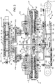
Figure 2 is a sectional view of some components of the system inFigure 1 ; and -
Figure 3 is a functional diagram of the system inFigures 1 and2 . - Referring to
Figure 1 , reference numeral 1 indicates a hover-capable aircraft, in particular a helicopter basically comprising afuselage 2, amain rotor 3 located at the top of thefuselage 2 and rotating about an axis A, and atail rotor 4 located at one end of thefuselage 2 and rotating about its own axis transversal to axis A. - In greater detail, the
main rotor 3 comprises ahub 5 with axis A and on which a plurality ofblades 9 are cantilever mounted and hinged, and which extend radially to axis A. - The
blades 9 are hinged to thehub 5 such that their orientation can be changed with respect to their axes of extension, so as to adjust the respective pitch angles with respect to the airflow. - More specifically, the helicopter 1 comprises:
- a pilot-
operable flight control 10 known as the "collective pitch" and operable to collectively vary the pitch angles of theblades 9, thereby causing an increase or decrease in the lift generated by the helicopter 1; - a pilot-
operable flight control 11 known as the "cyclic pitch" and operable to cyclically vary the pitch angle of theblades 9 according to the relative positions with respect to axis A; and - a plurality of
actuators 12, three in the case shown, controlled by theflight controls 11 and operatively connected to theblades 9 to adjust the respective pitch angles, on the basis of theflight controls - The
rotor 4 comprises ahub 13 with axis B and on which a plurality ofblades 14 are hinged in a cantilever manner, and which extend radially to axis A. - The
blades 14 are hinged on thehub 5 such that their orientation with respect to the associated axes of extension can be varied collectively, so as to adjust the respective pitch angles with respect to the airflow. - The helicopter 1 also comprises:
- a pilot-
operable flight control 15 for collectively varying the pitch angles of theblades 14, thereby controlling the yaw of the helicopter 1; and - an
actuator 16 controlled by the flight controls 15 and operatively connected to theblades 14 to adjust the respective pitch angles, on the basis of theflight control 15. - The helicopter 1 also comprises, for each actuator 12, 16 (
Figure 3 ): - a
respective lever 19 operatively connected to one or more respective flight controls 10, 11, 15; - a respective stability and
command augmentation system 20, referred to hereinafter as theSCAS 20; and - a
respective adder lever 21. - In the following description, reference will be made to a
single actuator 12 and the associatedSCAS 20, as all theactuators 12 andSCASes 20 are identical. - In greater detail, the
lever 19 takes a position determined by therespective flight control respective flight control - The
SCAS 20 comprises anoutput member 22, which transmits an input signal xd. - The
adder lever 21 is connected to theoutput member 22 and to thelever 19, and provides an output signal xv equal to the sum of the input signals xi and xd. - In particular, the
adder lever 21 comprises: - a
segment 23 connected to thelever 19 at point G; and - a
segment 24 connected to theoutput member 22 and tosegment 23. - The
adder lever 21 controls, as will become clear in the following description, the position of theactuator 12, and therefore of the associatedflight control - Due to this configuration, the input signal xd generated by the
SCAS 20 is added to the input signal xi generated by the pilot via the flight controls 11, 15, forming the output signal xv that enables stabilizing the helicopter 1 with respect to external disturbances. - In the case shown, the
lever 19 is hinged about a moveable fulcrum C, theadder lever 21 is fixed to thelever 19 at shared point D, and theoutput member 22 is free to travel. - In particular, the
SCAS 20 comprises: - an
actuator 26 configured to control the position of theoutput member 22 and so determine input signal xd; and - a pair of
control valves 27 controlled by theadder lever 21 and designed to control the position of theactuator 12, and, consequently, of the associatedflight control - Advantageously, the
actuator 26 comprises: - a
casing 30; - a pair of
pistons casing 30 and operatively connected to theoutput member 22; and - control means 33 (only shown schematically in
Figure 3 ) configured to exert a first force on thepiston 31 and a second force on thepiston 32; the first and the second force being independent of each other. -
Actuator 26 also comprises arod 34 sliding inside thecasing 30 and on which thepistons - In other words, the
pistons rod 34 form a pair of moveable elements arranged in series with respect to one another and respectively subjected to the first force and the second force. - The
rod 34 is integrally moveable with theoutput member 22. - In the case shown, the
rod 34 and thepistons single output member 22. - Referring to
Figure 3 , thecasing 30 comprises a pair ofchambers pistons - Each
chamber respective openings respective piston -
Actuator 26 also comprises alimit unit 60 to limit the travel of therod 34 between two end positions. In consequence, thislimit unit 60 limits the travel range of input xd generated by theSCAS 20. - In the case shown, the maximum travel range of input xd is a portion, for example 10%, of the maximum travel range of input xi.
- Preferably, the
limit unit 60 is configured so as to make the maximum travel range of input xd adjustable, according to the operating needs of theactuator - In greater detail, the
limit unit 60 is carried byactuator 26. - In the case shown, the
limit unit 60 comprises (Figure 2 ): - an internally threaded
cylinder 61 having an axis orthogonal to the axis of therod 34, through which therod 34 passes, and is arranged with play inside an unloadedportion 63 of therod 34; and - a threaded
head 62 screwed on thecylinder 61. - The
cylinder 61 allows translation of therod 34 for travel equal to the semidifference between the length of the unloadedportion 63 and the diameter of thecylinder 61 measured parallel to the sliding direction of therod 34. - When it is necessary to adjust the maximum travel range of input xd, it is sufficient to vary the diameter of the
cylinder 61 inserted in the unloadedportion 63, so as to enable adjustment of the maximum travel of therod 34. -
Actuator 26 also comprises a pair ofsprings rod 34 and designed to elastically preload therod 34 in a desired centred position. - The control means 33 comprise, for each
piston chamber 35, 36: - an associated
valve inlets outlet 45; - an associated
valve inlets outlets - a
line 58 fluidically connected to an environment containing oil under pressure and to theinlet 43 of the associatedvalve - a
line 59 fluidically connected to an environment at a discharge pressure and to theinlet 44 of the associatedvalve bypass 57 fluidically connected to theinlet 47 of the associatedvalve - Each
valve - to a respective first position (shown in
Figure 3 ), where it fluidically connectsinlet 43 andoutlet 45 anddischarges inlet 44; and - to a respective second position, where it discharges
inlet 43 and fluidically connectsinlet 44 withoutlet 45. - Each
valve - to a respective first position, where it fluidically connects
inlets outlets openings - to a respective second position, where it fluidically connects
inlets outlets openings - to a third respective position (shown in
Figure 3 ), where theinlets outlets - The control means 33 also comprise:
- a control unit 51 (shown schematically in
Figure 3 ) and programmed to control thevalves piston 31; and - a control unit 52 (shown schematically in
Figure 3 ) and programmed to control thevalves piston 32; and - a
backup control unit 53 to use in the event of failure of one of thecontrol units - The
control units digital buses 54 to aflight control system 55 of the helicopter 1. - In greater detail, the
flight control system 55 is programmed to determine a desired travel value for therod 34 on the basis of measured values of certain significant characteristics of the position and attitude of the helicopter 1 and corresponding desired values for these characteristics, in order to stabilize the helicopter 1. - The
flight control system 55 is also programmed to transmit this desired value to thecontrol units digital buses 54. - The
control units - calculate, on the basis of this desired value, opportune control rules for the
valves - transmit a feedback signal to the
flight control system 55. In this way, the control means 33 adjust the first and the second values of force acting onpistons - The helicopter 1 also comprises a lever 80 (
Figures 2 and3 ) operatively connected to theadder lever 21 at its section F, sliding parallel to a direction E, and designed to command thecontrol valves 27. - More specifically, the
lever 80 comprises a pair ofarms 81 arranged on respective opposite sides of section F. - Referring to
Figure 3 , eachcontrol valve 27 comprises: - a pair of
inlets outlets respective valve - a pair of
outlets - Each
control valve 27 is movable by the respective arm of thelever 80 between: - a first neutral position (shown in
Figure 3 ), where theinlets - a second position, where
inlets outlets - a third position, wherein
inlets outlets - More specifically, the
control valves 27 are normally arranged in the respective first neutral positions, are moved by the associatedarms 81 of thelever 80 to the respective second positions or third positions following operation of thecontrol lever 19 and return to the respective first positions once the actuator 12 has reached the desired position. - Referring to
Figure 2 , eachcontrol valve 27 comprises: - a
casing 86 defining theinlets outlets - a
piston 87 sealingly sliding inside thecasing 86 and connected to arespective arm 81 of thelever 80. - The
casing 86 and thepiston 87 of eachcontrol valve 27 in turn define: - a
chamber 92, into which the associatedinlet 88 andoutlet 90 face; and - a
chamber 93, into which the associatedinlet 89 andoutlet 91 face. - The
actuator 12 comprises: - a
casing 95; and - a
piston 96, in turn comprising arod 97 and a pair ofridges rod 97 and sealingly sliding inside thecasing 95. - The
casing 95 and theridge 98 define a pair ofchambers ridge 98 and provided withrespective inlets respective outlets control valves 27. Thecasing 95 and theridge 99 define a pair ofchambers ridge 99 and provided withrespective inlets respective outlets other control valve 27. - In this way, the
control valves 27 control the position of therod 97 of theactuator 12 on the basis of the position oflever 80 and, in consequence, of theadder lever 21. - Finally, the
rod 97 comprises afeedback lever 110 connected to therespective lever 19. - In greater detail, the
feedback lever 110 is connected to anaxial end 111 of therod 97 positioned externally to thecasing 95. - The
feedback lever 110 is also connected to lever 19 at fulcrum C, so as to cause, following translation of therod 97, the translation of theadder lever 21 and of point D so thatlever 80 is returned to the respective neutral position. - Operation of the helicopter 1 is described with reference to just actuator 12, just the corresponding
lever 19,adder lever 21 andoutput member 22, and just the correspondingSCAS 20. - Furthermore, operation of the helicopter 1 is described starting from the configuration shown in
Figure 2 , wherelever 80 keeps thecontrol valves 27 in the respective first neutral positions. In this configuration,piston 96 and therefore theblades - In greater detail, the pilot acts on the
flight control lever 19 about fulcrum C by an angle associated with the command given by the pilot and generating input signal xi. - The
flight control system 55 generates a desired translation value for theoutput member 22 and the rod 34 (for example towards the right, referring toFigures 2 and3 ), and the corresponding second input signal xd. These desired translation values and input signals are determined based on a comparison between measured values of certain significant characteristics of the position and attitude of the helicopter 1 and corresponding desired values for these characteristics. - These desired translation values are transmitted by the
flight control system 55 to thecontrol units SCAS 20 by respectivedigital buses 54. - The
control units SCAS 20 control thevalves 41apistons actuator 26, thereby causing the movement of therod 34 and theoutput member 22. - More specifically, the oil under pressure circulating in
line 58 determines the first and the second force on therespective pistons rod 34 in the position associated with the second input signal xd. - It is important to stress that the
pistons pistons rod 34. - The
limit unit 60 limits the travel of therod 34 between two end positions, limiting the travel range of input signal xd to an opportune fraction of input signal xi. - It is important to stress that the travel range of input signal xd, and consequently the distance between the aforementioned two end positions, is adjustable according to the operating needs of the
actuator 12. - The
adder lever 21 is translated by a distance equal to the sum oflever 19 and theoutput member 22, resulting in an output signal xv equal to the sum of the input signals xi and xd. - In this way, the command given by the pilot via the flight controls 10, 11, 15 is added to the input signal xd generated by the
SCAS 20, so as to stabilize the behaviour of the helicopter 1 with respect to external disturbances. - The output signal xv is transmitted by the
adder lever 21 to theactuator 12 vialever 80 and thecontrol valves 27. - More specifically, the translation of the adder levers 21 causes translation of the
arms 81 oflever 80 parallel to direction E, for example towards the right, referring toFigures 2 and3 . - This translation causes each
control valve 27 to move from the corresponding first neutral position to the respective second position or third position. - More specifically, the translation of the
arms 81 causes translation of thepistons 87 of thecontrol valves 27, thereby varying the pressure inside thechambers 101 of theactuator 12 and, consequently, moving thepiston 96 connected to theblades - The
feedback lever 110 translates together with therod 97 ofpiston 96 and causes translation of fulcrum C and consequently of point D and section F, the adder levers 21 and thearms 81, so as to return thecontrol valves 27 to the respective first neutral positions again and keep the actuator 12 in the second operating position. - From examination of the
SCAS 20 and the method according to the present invention, the advantages that can be obtained therewith are evident. - In particular, the
SCAS 20 comprises a pair ofpistons casing 30 and operatively connected to themovable member 22, and control means 33 configured to exert the first and the second mutually different forces on thepistons - In other words, the
pistons - Due to this, it is possible to maintain full authority of the
actuator pistons - In greater detail, in the event of failure of one of the
valves piston 31, 32 - it is sufficient that the control means 33 intervene by isolating the failed valve by operating therespective valve active valve actuator 12, 16 - to any position. - In other words, in the event of failure of one of the
valves piston valves actuator 12. - In this way, with particular reference to the hardover condition of one of the
pistons actuators 12 cannot be achieved, even if only for a few fractions of a second, is mitigated. - Due to the fact that the
pistons SCAS 20, simplifying the manufacture and maintenance of the latter. This is particularly advantageous when considering the fact that the space available for these levers is very limited. - In addition, the
control units SCAS 20 and are programmed to: - determine opportune control rules for the
valves - transmit the feedback signal to the
flight control system 55. - In this way, it is possible to reduce the cabling between the
flight control system 55 and theSCASes 20, and reduce the risk that the inevitable interference generated in the helicopter 1 can alter the correct transmission of the signals with respect to solutions of a known type and described in the introductory part of this description. - The helicopter 1 also comprises a plurality of
limit devices 60, which enable adjusting the maximum travel range of the second input xd according to the operating characteristics of therespective actuators 12, so as to optimize operation of the helicopter 1. - Finally, it is clear that modifications and variants can be made regarding the
SCAS 20 without departing from the protective scope defined in the claims. - Likewise, the helicopter 1 could be an aeroplane with direct flight controls 10, 11, 15, i.e. that are connected directly to the flight surfaces, in a mechanical or hydraulic manner.
Claims (9)
- A stability and command augmentation system (20) for an aircraft (1), comprising:- a first member (19) moveable by a pilot input device (10, 11, 15) to a first position defining a first input (xi);- a second member (22) moveable to a second position associated with a second input (xd); and- an adder device (21) configured to add said first and second inputs (xi, xd), and supply an output signal (xv) defining a command for an element to be controlled (9, 14) of said aircraft (1);- a casing (30);- a first and a second piston (31, 32) integrally movable with one another inside said casing (30) and operatively connected to said second member (22); and- control means (33) configured to exert a first force on said first piston and a second force on said second piston (31, 32) ;said second force being, in use, independent of said first force;
said system (20) further comprising:- a first valve (42a) configured to exert said first force on said first piston (31); and- at least a second valve (42b) configured to exert said second force on said second piston (32);said casing (30) defining a first chamber (35) and a second chamber (36) inside of which said first and second pistons (31, 32) sealingly slide, respectively;
said first valve (42a) being selectively controllable to create a first differential pressure value in first portions of said first chamber (35) arranged at respective opposite ends of said first piston (31);
said second valve (42b) being selectively controllable to create a second differential pressure value in second portions of said second chamber (36) arranged at respective opposite
3t ends of said second piston (32);
said system (20) further comprising a rod (34) sliding inside said casing (30), on which said first and second pistons (31, 32) are fixed and integrally movable with said second member (22) ;
characterized in that it comprises an adjustable limit device (60) for the travel of said second member (22) between a first and a second stop position;
at least one of said first and second stop positions being selectively adjustable;
said adjustable limit device (60) comprising:- an internally threaded cylinder (61) having an axis orthogonal to the axis of said rod (34), through which said rod (34) passes, and is arranged with play inside an unloaded portion (63) of said rod (34); and- a threaded head (62) screwed on said cylinder (61). - The system according to claim 1, characterized in that said control means (33) are electronically connectable to a flight control system (55) to receive a command associated with said second input signal (xi) and are programmed to move said second member (22) on the basis of said command.
- The system according to claim 2, characterized in that it comprises a digital bus (54) designed to transmit said command to said control means (33).
- The system according to claim 2 or 3, characterized in that said control means (33) comprise a first control unit (51) programmed to control said first valve (42a) and a second control unit (52) programmed to control said second valve (42b) .
- The system according to claim 4, characterized in that said control means (33) comprise a third backup control unit (53) .
- The system according to claim 5, characterized in that said limit device (60) is carried on said casing (31).
- An aircraft comprising:- at least one pilot-operable flight control (10, 11, 15);- at least one element to be controlled (9, 14);- at least one actuator (12, 16) operatively connected to said element to be controlled (9, 14) and said at least one flight control (10, 11, 15);- a flight control system (55); and- at least one stability and command augmentation system (20) according to any of the preceding claims.
- A stabilization and command method of an aircraft (1), comprising the steps of:i) operating a flight control (10, 11, 15) to move a first member (2) to a first position defining a first input (xi);ii) moving a second member (22) to a second position associated with a second input (xd); andiii) adding said first and second inputs to generate an output (xv) defining a command for an element to be controlled (9, 14) of said aircraft (1);iv) moving, by control means (33), a first and a second piston (31, 32) operatively connected to said second member (22) inside a casing (30);v) exerting a first force on said first piston (31) and a second force on said second piston (32); said second force being independent of said first force;vi) exerting said firt force on said first piston (31) by menas of a first valve (42a); andvii) exerting said second force on said second piston (32) by means of a second valve (42b);
said casing (30) defining a first chamber (35) and a second chamber (36) inside of which said first and second pistons (31, 32) sealingly slide, respectively;
said method further comprising the steps of:viii) selectively controlling said first valve (42a) to create a first differential pressure value in first portions of said first chamber (35) arranged at respective opposite ends of said first piston (31);ix) selectively controlling said second valve (42b) to create a second differential pressure value in second portions of said second chamber (36) arranged at respective opposite ends of said second piston (32);said system (20) further comprising a rod (34) sliding inside said casing (30), on which said first and second pistons (31, 32) are fixed and integrally movable with said second member (22) ;
said method further comprising the steps of:
x) limiting the travel of said second member (22) between a first and a second stop position;
characterized in that it comprises the further steps of:
xi) selectively adjusting at least one of at least one of said first and second stop positions;
said adjustable limit device (60) comprising:- an internally threaded cylinder (61) having an axis orthogonal to the axis of said rod (34), through which said rod (34) passes, and is arranged with play inside an unloaded portion (63) of said rod (34); and- a threaded head (62) screwed on said cylinder (61). - The method according to claim 8, characterized in that it comprises the steps of:xii) electronically connecting said control means (33) to a flight control system (55) to receive a command associated with said second input signal (xi); andxiii) moving said second member (22) on the basis of said command.
Priority Applications (7)
| Application Number | Priority Date | Filing Date | Title |
|---|---|---|---|
| EP19194312.5A EP3598263A1 (en) | 2017-10-05 | 2017-10-05 | Stability and command augmentation system for an aircraft |
| EP17194901.9A EP3467608B1 (en) | 2017-10-05 | 2017-10-05 | Stability and command augmentation system for an aircraft |
| PCT/IB2018/057759 WO2019069287A1 (en) | 2017-10-05 | 2018-10-05 | Stability and command augmentation system for an aircraft, and stabilization and control method of an aircraft |
| KR1020207012057A KR102595259B1 (en) | 2017-10-05 | 2018-10-05 | Stability and command augmentation system for aircraft, and methods for stabilizing and controlling aircraft |
| US16/649,745 US11435760B2 (en) | 2017-10-05 | 2018-10-05 | Stability and command augmentation system for an aircraft, and stabilization and control method of an aircraft |
| RU2020112976A RU2770932C2 (en) | 2017-10-05 | 2018-10-05 | Aircraft stabilization and control system (versions), aircraft stabilization and control method, aircraft (options) |
| CN201880064812.9A CN111194432B (en) | 2017-10-05 | 2018-10-05 | Aircraft stability control enhancement system and aircraft stability and control method |
Applications Claiming Priority (1)
| Application Number | Priority Date | Filing Date | Title |
|---|---|---|---|
| EP17194901.9A EP3467608B1 (en) | 2017-10-05 | 2017-10-05 | Stability and command augmentation system for an aircraft |
Related Child Applications (2)
| Application Number | Title | Priority Date | Filing Date |
|---|---|---|---|
| EP19194312.5A Division EP3598263A1 (en) | 2017-10-05 | 2017-10-05 | Stability and command augmentation system for an aircraft |
| EP19194312.5A Division-Into EP3598263A1 (en) | 2017-10-05 | 2017-10-05 | Stability and command augmentation system for an aircraft |
Publications (2)
| Publication Number | Publication Date |
|---|---|
| EP3467608A1 EP3467608A1 (en) | 2019-04-10 |
| EP3467608B1 true EP3467608B1 (en) | 2019-12-04 |
Family
ID=60484100
Family Applications (2)
| Application Number | Title | Priority Date | Filing Date |
|---|---|---|---|
| EP19194312.5A Withdrawn EP3598263A1 (en) | 2017-10-05 | 2017-10-05 | Stability and command augmentation system for an aircraft |
| EP17194901.9A Active EP3467608B1 (en) | 2017-10-05 | 2017-10-05 | Stability and command augmentation system for an aircraft |
Family Applications Before (1)
| Application Number | Title | Priority Date | Filing Date |
|---|---|---|---|
| EP19194312.5A Withdrawn EP3598263A1 (en) | 2017-10-05 | 2017-10-05 | Stability and command augmentation system for an aircraft |
Country Status (6)
| Country | Link |
|---|---|
| US (1) | US11435760B2 (en) |
| EP (2) | EP3598263A1 (en) |
| KR (1) | KR102595259B1 (en) |
| CN (1) | CN111194432B (en) |
| RU (1) | RU2770932C2 (en) |
| WO (1) | WO2019069287A1 (en) |
Families Citing this family (4)
| Publication number | Priority date | Publication date | Assignee | Title |
|---|---|---|---|---|
| CH717147A2 (en) * | 2020-02-18 | 2021-08-31 | Marenco Ag | Hydraulic servo actuator. |
| CN112173143B (en) * | 2020-09-25 | 2022-09-13 | 中国直升机设计研究所 | Emergency substitution device for helicopter tail rotor in failure state and control method |
| EP4155196A1 (en) * | 2021-09-27 | 2023-03-29 | Microtecnica S.r.l. | Stability control augmentation system and method |
| EP4194334A1 (en) * | 2021-12-08 | 2023-06-14 | Microtecnica S.r.l. | Stability and control augmentation system |
Family Cites Families (16)
| Publication number | Priority date | Publication date | Assignee | Title |
|---|---|---|---|---|
| US3295420A (en) * | 1964-12-14 | 1967-01-03 | Boeing Co | Hydraulic actuator |
| US3482486A (en) * | 1967-11-29 | 1969-12-09 | United Aircraft Corp | Redundant control method and apparatus |
| US3561322A (en) * | 1968-06-04 | 1971-02-09 | Boeing Co | Stability augmentation system |
| US3561222A (en) | 1969-01-30 | 1971-02-09 | James C Sweeton | Apparatus for laying underground cable, wire, pipe, or the like |
| FR2119828B1 (en) * | 1970-12-14 | 1974-02-15 | Aerospatiale | |
| US5678786A (en) * | 1995-12-06 | 1997-10-21 | Mcdonnell Douglas Helicopter Co. | Reconfigurable helicopter flight control system |
| JP3012644B1 (en) * | 1999-03-18 | 2000-02-28 | 株式会社コミュータヘリコプタ先進技術研究所 | Servo actuator device and aircraft operation control device |
| US7108232B2 (en) * | 2004-02-05 | 2006-09-19 | Hoh Roger H | Helicopter force-feel and stability augmentation system with parallel servo-actuator |
| US7156056B2 (en) * | 2004-06-10 | 2007-01-02 | Achates Power, Llc | Two-cycle, opposed-piston internal combustion engine |
| US8386093B2 (en) * | 2007-04-05 | 2013-02-26 | Bombardier Inc. | Multi-axis serially redundant, single channel, multi-path fly-by-wire flight control system |
| US7882778B2 (en) * | 2008-03-11 | 2011-02-08 | Woodward Hrt, Inc. | Hydraulic actuator with floating pistons |
| WO2013120031A1 (en) * | 2012-02-10 | 2013-08-15 | Merlin Technology, Inc. | Autopilot control arrangement and methods |
| US8967552B2 (en) * | 2012-10-19 | 2015-03-03 | Bell Helicopter Textron Inc. | Direct-drive control of aircraft stability augmentation |
| EP2913265B1 (en) * | 2014-02-27 | 2019-07-17 | Goodrich Actuation Systems SAS | Stability and control augmentation system |
| ES2769860T3 (en) | 2014-05-23 | 2020-06-29 | Grundfos Holding As | Pump control method |
| RU2578706C1 (en) * | 2014-11-20 | 2016-03-27 | Открытое акционерное общество "Казанский вертолетный завод" | Summing mechanism for control systems of common and cyclic pitch of helicopters of three-point control system with inclined arrangement of hydraulic actuators |
-
2017
- 2017-10-05 EP EP19194312.5A patent/EP3598263A1/en not_active Withdrawn
- 2017-10-05 EP EP17194901.9A patent/EP3467608B1/en active Active
-
2018
- 2018-10-05 KR KR1020207012057A patent/KR102595259B1/en active IP Right Grant
- 2018-10-05 RU RU2020112976A patent/RU2770932C2/en active
- 2018-10-05 WO PCT/IB2018/057759 patent/WO2019069287A1/en active Application Filing
- 2018-10-05 US US16/649,745 patent/US11435760B2/en active Active
- 2018-10-05 CN CN201880064812.9A patent/CN111194432B/en active Active
Non-Patent Citations (1)
| Title |
|---|
| None * |
Also Published As
| Publication number | Publication date |
|---|---|
| RU2770932C2 (en) | 2022-04-25 |
| EP3598263A1 (en) | 2020-01-22 |
| KR20200090758A (en) | 2020-07-29 |
| RU2020112976A3 (en) | 2022-03-09 |
| KR102595259B1 (en) | 2023-10-27 |
| US20200278698A1 (en) | 2020-09-03 |
| WO2019069287A1 (en) | 2019-04-11 |
| EP3467608A1 (en) | 2019-04-10 |
| US11435760B2 (en) | 2022-09-06 |
| CN111194432B (en) | 2024-03-26 |
| RU2020112976A (en) | 2021-10-06 |
| CN111194432A (en) | 2020-05-22 |
Similar Documents
| Publication | Publication Date | Title |
|---|---|---|
| US11435760B2 (en) | Stability and command augmentation system for an aircraft, and stabilization and control method of an aircraft | |
| EP3126231B1 (en) | Elevator load alleviating control for a rotary wing aircraft | |
| GB2196588A (en) | Rudder control arrangement for aircraft | |
| US11235861B2 (en) | Horizontal stabilizer trim actuator systems and methods | |
| US11827336B2 (en) | Propeller blade angle closed loop control by solenoid modulation | |
| US10836478B2 (en) | Separation of collective and cyclic actuation | |
| US3272062A (en) | Servo valve synchronizer | |
| CA2580276C (en) | Mechanical flight control auxiliary power assist system | |
| US7890222B1 (en) | Mechanical flight control auxiliary power assist system | |
| US10570936B2 (en) | Symmetrically loaded dual hydraulic fly-by-wire actuator | |
| US11584511B2 (en) | Servo-actuator architecture with electromechanical-stability and control augmentation system | |
| US4362085A (en) | Flight control system | |
| US9470248B2 (en) | Flexible response secured mechanical balancing for multiple control actuators with a common output | |
| US3358565A (en) | Redundant actuator | |
| EP3505440B1 (en) | Horizontal stabilizer trim actuator assembly | |
| CN107709156B (en) | Device for controlling a propeller of a turboprop engine with variable-pitch blades | |
| US9260179B2 (en) | Propeller and system of counter-rotating propellers comprising improved means for limiting pitch, and a turbine engine comprising them | |
| US2855900A (en) | Fluid pressure servo system with valve actuating means having a differential feel | |
| EP2627913A1 (en) | Floating piston actuator for operation with multiple hydraulic systems | |
| US3901128A (en) | Fluid powered control system and fail-safe valving system for a fluid powered system | |
| Jacazio et al. | A dual-duplex electrohydraulic system for the fly-by-wire control of a helicopter main rotor |
Legal Events
| Date | Code | Title | Description |
|---|---|---|---|
| PUAI | Public reference made under article 153(3) epc to a published international application that has entered the european phase |
Free format text: ORIGINAL CODE: 0009012 |
|
| STAA | Information on the status of an ep patent application or granted ep patent |
Free format text: STATUS: REQUEST FOR EXAMINATION WAS MADE |
|
| 17P | Request for examination filed |
Effective date: 20180925 |
|
| AK | Designated contracting states |
Kind code of ref document: A1 Designated state(s): AL AT BE BG CH CY CZ DE DK EE ES FI FR GB GR HR HU IE IS IT LI LT LU LV MC MK MT NL NO PL PT RO RS SE SI SK SM TR |
|
| AX | Request for extension of the european patent |
Extension state: BA ME |
|
| GRAJ | Information related to disapproval of communication of intention to grant by the applicant or resumption of examination proceedings by the epo deleted |
Free format text: ORIGINAL CODE: EPIDOSDIGR1 |
|
| GRAP | Despatch of communication of intention to grant a patent |
Free format text: ORIGINAL CODE: EPIDOSNIGR1 |
|
| GRAP | Despatch of communication of intention to grant a patent |
Free format text: ORIGINAL CODE: EPIDOSNIGR1 |
|
| STAA | Information on the status of an ep patent application or granted ep patent |
Free format text: STATUS: GRANT OF PATENT IS INTENDED |
|
| INTG | Intention to grant announced |
Effective date: 20190516 |
|
| INTC | Intention to grant announced (deleted) | ||
| INTG | Intention to grant announced |
Effective date: 20190528 |
|
| GRAS | Grant fee paid |
Free format text: ORIGINAL CODE: EPIDOSNIGR3 |
|
| GRAA | (expected) grant |
Free format text: ORIGINAL CODE: 0009210 |
|
| STAA | Information on the status of an ep patent application or granted ep patent |
Free format text: STATUS: THE PATENT HAS BEEN GRANTED |
|
| RIN1 | Information on inventor provided before grant (corrected) |
Inventor name: GAGLIOSTRO, DAVIDE Inventor name: CASOLA, DAVIDE Inventor name: VANNI, ROBERTO |
|
| AK | Designated contracting states |
Kind code of ref document: B1 Designated state(s): AL AT BE BG CH CY CZ DE DK EE ES FI FR GB GR HR HU IE IS IT LI LT LU LV MC MK MT NL NO PL PT RO RS SE SI SK SM TR |
|
| REG | Reference to a national code |
Ref country code: GB Ref legal event code: FG4D |
|
| REG | Reference to a national code |
Ref country code: CH Ref legal event code: EP |
|
| REG | Reference to a national code |
Ref country code: AT Ref legal event code: REF Ref document number: 1210170 Country of ref document: AT Kind code of ref document: T Effective date: 20191215 |
|
| REG | Reference to a national code |
Ref country code: DE Ref legal event code: R096 Ref document number: 602017009292 Country of ref document: DE |
|
| REG | Reference to a national code |
Ref country code: IE Ref legal event code: FG4D |
|
| REG | Reference to a national code |
Ref country code: NL Ref legal event code: MP Effective date: 20191204 |
|
| REG | Reference to a national code |
Ref country code: LT Ref legal event code: MG4D |
|
| PG25 | Lapsed in a contracting state [announced via postgrant information from national office to epo] |
Ref country code: SE Free format text: LAPSE BECAUSE OF FAILURE TO SUBMIT A TRANSLATION OF THE DESCRIPTION OR TO PAY THE FEE WITHIN THE PRESCRIBED TIME-LIMIT Effective date: 20191204 Ref country code: LV Free format text: LAPSE BECAUSE OF FAILURE TO SUBMIT A TRANSLATION OF THE DESCRIPTION OR TO PAY THE FEE WITHIN THE PRESCRIBED TIME-LIMIT Effective date: 20191204 Ref country code: LT Free format text: LAPSE BECAUSE OF FAILURE TO SUBMIT A TRANSLATION OF THE DESCRIPTION OR TO PAY THE FEE WITHIN THE PRESCRIBED TIME-LIMIT Effective date: 20191204 Ref country code: GR Free format text: LAPSE BECAUSE OF FAILURE TO SUBMIT A TRANSLATION OF THE DESCRIPTION OR TO PAY THE FEE WITHIN THE PRESCRIBED TIME-LIMIT Effective date: 20200305 Ref country code: FI Free format text: LAPSE BECAUSE OF FAILURE TO SUBMIT A TRANSLATION OF THE DESCRIPTION OR TO PAY THE FEE WITHIN THE PRESCRIBED TIME-LIMIT Effective date: 20191204 Ref country code: NO Free format text: LAPSE BECAUSE OF FAILURE TO SUBMIT A TRANSLATION OF THE DESCRIPTION OR TO PAY THE FEE WITHIN THE PRESCRIBED TIME-LIMIT Effective date: 20200304 Ref country code: BG Free format text: LAPSE BECAUSE OF FAILURE TO SUBMIT A TRANSLATION OF THE DESCRIPTION OR TO PAY THE FEE WITHIN THE PRESCRIBED TIME-LIMIT Effective date: 20200304 |
|
| PG25 | Lapsed in a contracting state [announced via postgrant information from national office to epo] |
Ref country code: RS Free format text: LAPSE BECAUSE OF FAILURE TO SUBMIT A TRANSLATION OF THE DESCRIPTION OR TO PAY THE FEE WITHIN THE PRESCRIBED TIME-LIMIT Effective date: 20191204 Ref country code: HR Free format text: LAPSE BECAUSE OF FAILURE TO SUBMIT A TRANSLATION OF THE DESCRIPTION OR TO PAY THE FEE WITHIN THE PRESCRIBED TIME-LIMIT Effective date: 20191204 |
|
| PG25 | Lapsed in a contracting state [announced via postgrant information from national office to epo] |
Ref country code: AL Free format text: LAPSE BECAUSE OF FAILURE TO SUBMIT A TRANSLATION OF THE DESCRIPTION OR TO PAY THE FEE WITHIN THE PRESCRIBED TIME-LIMIT Effective date: 20191204 |
|
| PG25 | Lapsed in a contracting state [announced via postgrant information from national office to epo] |
Ref country code: RO Free format text: LAPSE BECAUSE OF FAILURE TO SUBMIT A TRANSLATION OF THE DESCRIPTION OR TO PAY THE FEE WITHIN THE PRESCRIBED TIME-LIMIT Effective date: 20191204 Ref country code: PT Free format text: LAPSE BECAUSE OF FAILURE TO SUBMIT A TRANSLATION OF THE DESCRIPTION OR TO PAY THE FEE WITHIN THE PRESCRIBED TIME-LIMIT Effective date: 20200429 Ref country code: EE Free format text: LAPSE BECAUSE OF FAILURE TO SUBMIT A TRANSLATION OF THE DESCRIPTION OR TO PAY THE FEE WITHIN THE PRESCRIBED TIME-LIMIT Effective date: 20191204 Ref country code: ES Free format text: LAPSE BECAUSE OF FAILURE TO SUBMIT A TRANSLATION OF THE DESCRIPTION OR TO PAY THE FEE WITHIN THE PRESCRIBED TIME-LIMIT Effective date: 20191204 Ref country code: NL Free format text: LAPSE BECAUSE OF FAILURE TO SUBMIT A TRANSLATION OF THE DESCRIPTION OR TO PAY THE FEE WITHIN THE PRESCRIBED TIME-LIMIT Effective date: 20191204 Ref country code: CZ Free format text: LAPSE BECAUSE OF FAILURE TO SUBMIT A TRANSLATION OF THE DESCRIPTION OR TO PAY THE FEE WITHIN THE PRESCRIBED TIME-LIMIT Effective date: 20191204 |
|
| PG25 | Lapsed in a contracting state [announced via postgrant information from national office to epo] |
Ref country code: SK Free format text: LAPSE BECAUSE OF FAILURE TO SUBMIT A TRANSLATION OF THE DESCRIPTION OR TO PAY THE FEE WITHIN THE PRESCRIBED TIME-LIMIT Effective date: 20191204 Ref country code: IS Free format text: LAPSE BECAUSE OF FAILURE TO SUBMIT A TRANSLATION OF THE DESCRIPTION OR TO PAY THE FEE WITHIN THE PRESCRIBED TIME-LIMIT Effective date: 20200404 Ref country code: SM Free format text: LAPSE BECAUSE OF FAILURE TO SUBMIT A TRANSLATION OF THE DESCRIPTION OR TO PAY THE FEE WITHIN THE PRESCRIBED TIME-LIMIT Effective date: 20191204 |
|
| REG | Reference to a national code |
Ref country code: DE Ref legal event code: R097 Ref document number: 602017009292 Country of ref document: DE |
|
| REG | Reference to a national code |
Ref country code: AT Ref legal event code: MK05 Ref document number: 1210170 Country of ref document: AT Kind code of ref document: T Effective date: 20191204 |
|
| PLBE | No opposition filed within time limit |
Free format text: ORIGINAL CODE: 0009261 |
|
| STAA | Information on the status of an ep patent application or granted ep patent |
Free format text: STATUS: NO OPPOSITION FILED WITHIN TIME LIMIT |
|
| PG25 | Lapsed in a contracting state [announced via postgrant information from national office to epo] |
Ref country code: DK Free format text: LAPSE BECAUSE OF FAILURE TO SUBMIT A TRANSLATION OF THE DESCRIPTION OR TO PAY THE FEE WITHIN THE PRESCRIBED TIME-LIMIT Effective date: 20191204 |
|
| 26N | No opposition filed |
Effective date: 20200907 |
|
| PG25 | Lapsed in a contracting state [announced via postgrant information from national office to epo] |
Ref country code: PL Free format text: LAPSE BECAUSE OF FAILURE TO SUBMIT A TRANSLATION OF THE DESCRIPTION OR TO PAY THE FEE WITHIN THE PRESCRIBED TIME-LIMIT Effective date: 20191204 Ref country code: AT Free format text: LAPSE BECAUSE OF FAILURE TO SUBMIT A TRANSLATION OF THE DESCRIPTION OR TO PAY THE FEE WITHIN THE PRESCRIBED TIME-LIMIT Effective date: 20191204 |
|
| PG25 | Lapsed in a contracting state [announced via postgrant information from national office to epo] |
Ref country code: SI Free format text: LAPSE BECAUSE OF FAILURE TO SUBMIT A TRANSLATION OF THE DESCRIPTION OR TO PAY THE FEE WITHIN THE PRESCRIBED TIME-LIMIT Effective date: 20191204 |
|
| REG | Reference to a national code |
Ref country code: CH Ref legal event code: PL |
|
| PG25 | Lapsed in a contracting state [announced via postgrant information from national office to epo] |
Ref country code: LU Free format text: LAPSE BECAUSE OF NON-PAYMENT OF DUE FEES Effective date: 20201005 Ref country code: MC Free format text: LAPSE BECAUSE OF FAILURE TO SUBMIT A TRANSLATION OF THE DESCRIPTION OR TO PAY THE FEE WITHIN THE PRESCRIBED TIME-LIMIT Effective date: 20191204 |
|
| REG | Reference to a national code |
Ref country code: BE Ref legal event code: MM Effective date: 20201031 |
|
| PG25 | Lapsed in a contracting state [announced via postgrant information from national office to epo] |
Ref country code: LI Free format text: LAPSE BECAUSE OF NON-PAYMENT OF DUE FEES Effective date: 20201031 Ref country code: CH Free format text: LAPSE BECAUSE OF NON-PAYMENT OF DUE FEES Effective date: 20201031 Ref country code: BE Free format text: LAPSE BECAUSE OF NON-PAYMENT OF DUE FEES Effective date: 20201031 |
|
| PG25 | Lapsed in a contracting state [announced via postgrant information from national office to epo] |
Ref country code: IE Free format text: LAPSE BECAUSE OF NON-PAYMENT OF DUE FEES Effective date: 20201005 |
|
| PG25 | Lapsed in a contracting state [announced via postgrant information from national office to epo] |
Ref country code: TR Free format text: LAPSE BECAUSE OF FAILURE TO SUBMIT A TRANSLATION OF THE DESCRIPTION OR TO PAY THE FEE WITHIN THE PRESCRIBED TIME-LIMIT Effective date: 20191204 Ref country code: MT Free format text: LAPSE BECAUSE OF FAILURE TO SUBMIT A TRANSLATION OF THE DESCRIPTION OR TO PAY THE FEE WITHIN THE PRESCRIBED TIME-LIMIT Effective date: 20191204 Ref country code: CY Free format text: LAPSE BECAUSE OF FAILURE TO SUBMIT A TRANSLATION OF THE DESCRIPTION OR TO PAY THE FEE WITHIN THE PRESCRIBED TIME-LIMIT Effective date: 20191204 |
|
| PG25 | Lapsed in a contracting state [announced via postgrant information from national office to epo] |
Ref country code: MK Free format text: LAPSE BECAUSE OF FAILURE TO SUBMIT A TRANSLATION OF THE DESCRIPTION OR TO PAY THE FEE WITHIN THE PRESCRIBED TIME-LIMIT Effective date: 20191204 |
|
| P01 | Opt-out of the competence of the unified patent court (upc) registered |
Effective date: 20231005 |
|
| REG | Reference to a national code |
Ref country code: DE Ref legal event code: R079 Ref document number: 602017009292 Country of ref document: DE Free format text: PREVIOUS MAIN CLASS: G05D0001080000 Ipc: G05D0001490000 |
|
| PGFP | Annual fee paid to national office [announced via postgrant information from national office to epo] |
Ref country code: GB Payment date: 20231024 Year of fee payment: 7 |
|
| PGFP | Annual fee paid to national office [announced via postgrant information from national office to epo] |
Ref country code: IT Payment date: 20231006 Year of fee payment: 7 Ref country code: FR Payment date: 20231026 Year of fee payment: 7 Ref country code: DE Payment date: 20231027 Year of fee payment: 7 |