EP3467514A1 - Fluid device, system, and method of detecting specimen substance - Google Patents
Fluid device, system, and method of detecting specimen substance Download PDFInfo
- Publication number
- EP3467514A1 EP3467514A1 EP17810251.3A EP17810251A EP3467514A1 EP 3467514 A1 EP3467514 A1 EP 3467514A1 EP 17810251 A EP17810251 A EP 17810251A EP 3467514 A1 EP3467514 A1 EP 3467514A1
- Authority
- EP
- European Patent Office
- Prior art keywords
- flow channel
- circulation flow
- fluidic device
- sample substance
- shared
- Prior art date
- Legal status (The legal status is an assumption and is not a legal conclusion. Google has not performed a legal analysis and makes no representation as to the accuracy of the status listed.)
- Withdrawn
Links
Images



Classifications
-
- B—PERFORMING OPERATIONS; TRANSPORTING
- B01—PHYSICAL OR CHEMICAL PROCESSES OR APPARATUS IN GENERAL
- B01F—MIXING, e.g. DISSOLVING, EMULSIFYING OR DISPERSING
- B01F25/00—Flow mixers; Mixers for falling materials, e.g. solid particles
- B01F25/50—Circulation mixers, e.g. wherein at least part of the mixture is discharged from and reintroduced into a receptacle
- B01F25/54—Circulation mixers, e.g. wherein at least part of the mixture is discharged from and reintroduced into a receptacle provided with a pump inside the receptacle to recirculate the material within the receptacle
-
- B—PERFORMING OPERATIONS; TRANSPORTING
- B01—PHYSICAL OR CHEMICAL PROCESSES OR APPARATUS IN GENERAL
- B01L—CHEMICAL OR PHYSICAL LABORATORY APPARATUS FOR GENERAL USE
- B01L3/00—Containers or dishes for laboratory use, e.g. laboratory glassware; Droppers
- B01L3/50—Containers for the purpose of retaining a material to be analysed, e.g. test tubes
- B01L3/502—Containers for the purpose of retaining a material to be analysed, e.g. test tubes with fluid transport, e.g. in multi-compartment structures
- B01L3/5027—Containers for the purpose of retaining a material to be analysed, e.g. test tubes with fluid transport, e.g. in multi-compartment structures by integrated microfluidic structures, i.e. dimensions of channels and chambers are such that surface tension forces are important, e.g. lab-on-a-chip
- B01L3/502738—Containers for the purpose of retaining a material to be analysed, e.g. test tubes with fluid transport, e.g. in multi-compartment structures by integrated microfluidic structures, i.e. dimensions of channels and chambers are such that surface tension forces are important, e.g. lab-on-a-chip characterised by integrated valves
-
- B—PERFORMING OPERATIONS; TRANSPORTING
- B01—PHYSICAL OR CHEMICAL PROCESSES OR APPARATUS IN GENERAL
- B01F—MIXING, e.g. DISSOLVING, EMULSIFYING OR DISPERSING
- B01F23/00—Mixing according to the phases to be mixed, e.g. dispersing or emulsifying
- B01F23/40—Mixing liquids with liquids; Emulsifying
- B01F23/45—Mixing liquids with liquids; Emulsifying using flow mixing
- B01F23/451—Mixing liquids with liquids; Emulsifying using flow mixing by injecting one liquid into another
-
- B—PERFORMING OPERATIONS; TRANSPORTING
- B01—PHYSICAL OR CHEMICAL PROCESSES OR APPARATUS IN GENERAL
- B01F—MIXING, e.g. DISSOLVING, EMULSIFYING OR DISPERSING
- B01F25/00—Flow mixers; Mixers for falling materials, e.g. solid particles
- B01F25/50—Circulation mixers, e.g. wherein at least part of the mixture is discharged from and reintroduced into a receptacle
- B01F25/51—Circulation mixers, e.g. wherein at least part of the mixture is discharged from and reintroduced into a receptacle in which the mixture is circulated through a set of tubes, e.g. with gradual introduction of a component into the circulating flow
-
- B—PERFORMING OPERATIONS; TRANSPORTING
- B01—PHYSICAL OR CHEMICAL PROCESSES OR APPARATUS IN GENERAL
- B01F—MIXING, e.g. DISSOLVING, EMULSIFYING OR DISPERSING
- B01F35/00—Accessories for mixers; Auxiliary operations or auxiliary devices; Parts or details of general application
- B01F35/75—Discharge mechanisms
- B01F35/754—Discharge mechanisms characterised by the means for discharging the components from the mixer
- B01F35/7547—Discharge mechanisms characterised by the means for discharging the components from the mixer using valves, gates, orifices or openings
-
- B—PERFORMING OPERATIONS; TRANSPORTING
- B03—SEPARATION OF SOLID MATERIALS USING LIQUIDS OR USING PNEUMATIC TABLES OR JIGS; MAGNETIC OR ELECTROSTATIC SEPARATION OF SOLID MATERIALS FROM SOLID MATERIALS OR FLUIDS; SEPARATION BY HIGH-VOLTAGE ELECTRIC FIELDS
- B03C—MAGNETIC OR ELECTROSTATIC SEPARATION OF SOLID MATERIALS FROM SOLID MATERIALS OR FLUIDS; SEPARATION BY HIGH-VOLTAGE ELECTRIC FIELDS
- B03C1/00—Magnetic separation
-
- B—PERFORMING OPERATIONS; TRANSPORTING
- B81—MICROSTRUCTURAL TECHNOLOGY
- B81B—MICROSTRUCTURAL DEVICES OR SYSTEMS, e.g. MICROMECHANICAL DEVICES
- B81B1/00—Devices without movable or flexible elements, e.g. microcapillary devices
-
- B—PERFORMING OPERATIONS; TRANSPORTING
- B81—MICROSTRUCTURAL TECHNOLOGY
- B81B—MICROSTRUCTURAL DEVICES OR SYSTEMS, e.g. MICROMECHANICAL DEVICES
- B81B7/00—Microstructural systems ; Auxiliary parts of microstructural devices or systems
- B81B7/02—Microstructural systems ; Auxiliary parts of microstructural devices or systems containing distinct electrical or optical devices of particular relevance for their function, e.g. microelectro-mechanical systems [MEMS]
-
- C—CHEMISTRY; METALLURGY
- C12—BIOCHEMISTRY; BEER; SPIRITS; WINE; VINEGAR; MICROBIOLOGY; ENZYMOLOGY; MUTATION OR GENETIC ENGINEERING
- C12M—APPARATUS FOR ENZYMOLOGY OR MICROBIOLOGY; APPARATUS FOR CULTURING MICROORGANISMS FOR PRODUCING BIOMASS, FOR GROWING CELLS OR FOR OBTAINING FERMENTATION OR METABOLIC PRODUCTS, i.e. BIOREACTORS OR FERMENTERS
- C12M1/00—Apparatus for enzymology or microbiology
-
- C—CHEMISTRY; METALLURGY
- C12—BIOCHEMISTRY; BEER; SPIRITS; WINE; VINEGAR; MICROBIOLOGY; ENZYMOLOGY; MUTATION OR GENETIC ENGINEERING
- C12Q—MEASURING OR TESTING PROCESSES INVOLVING ENZYMES, NUCLEIC ACIDS OR MICROORGANISMS; COMPOSITIONS OR TEST PAPERS THEREFOR; PROCESSES OF PREPARING SUCH COMPOSITIONS; CONDITION-RESPONSIVE CONTROL IN MICROBIOLOGICAL OR ENZYMOLOGICAL PROCESSES
- C12Q1/00—Measuring or testing processes involving enzymes, nucleic acids or microorganisms; Compositions therefor; Processes of preparing such compositions
- C12Q1/68—Measuring or testing processes involving enzymes, nucleic acids or microorganisms; Compositions therefor; Processes of preparing such compositions involving nucleic acids
-
- G—PHYSICS
- G01—MEASURING; TESTING
- G01N—INVESTIGATING OR ANALYSING MATERIALS BY DETERMINING THEIR CHEMICAL OR PHYSICAL PROPERTIES
- G01N1/00—Sampling; Preparing specimens for investigation
- G01N1/28—Preparing specimens for investigation including physical details of (bio-)chemical methods covered elsewhere, e.g. G01N33/50, C12Q
- G01N1/38—Diluting, dispersing or mixing samples
-
- G—PHYSICS
- G01—MEASURING; TESTING
- G01N—INVESTIGATING OR ANALYSING MATERIALS BY DETERMINING THEIR CHEMICAL OR PHYSICAL PROPERTIES
- G01N35/00—Automatic analysis not limited to methods or materials provided for in any single one of groups G01N1/00 - G01N33/00; Handling materials therefor
- G01N35/08—Automatic analysis not limited to methods or materials provided for in any single one of groups G01N1/00 - G01N33/00; Handling materials therefor using a stream of discrete samples flowing along a tube system, e.g. flow injection analysis
-
- G—PHYSICS
- G01—MEASURING; TESTING
- G01N—INVESTIGATING OR ANALYSING MATERIALS BY DETERMINING THEIR CHEMICAL OR PHYSICAL PROPERTIES
- G01N37/00—Details not covered by any other group of this subclass
-
- B—PERFORMING OPERATIONS; TRANSPORTING
- B01—PHYSICAL OR CHEMICAL PROCESSES OR APPARATUS IN GENERAL
- B01L—CHEMICAL OR PHYSICAL LABORATORY APPARATUS FOR GENERAL USE
- B01L2200/00—Solutions for specific problems relating to chemical or physical laboratory apparatus
- B01L2200/06—Fluid handling related problems
- B01L2200/0647—Handling flowable solids, e.g. microscopic beads, cells, particles
- B01L2200/0668—Trapping microscopic beads
-
- B—PERFORMING OPERATIONS; TRANSPORTING
- B01—PHYSICAL OR CHEMICAL PROCESSES OR APPARATUS IN GENERAL
- B01L—CHEMICAL OR PHYSICAL LABORATORY APPARATUS FOR GENERAL USE
- B01L2300/00—Additional constructional details
- B01L2300/06—Auxiliary integrated devices, integrated components
- B01L2300/0627—Sensor or part of a sensor is integrated
- B01L2300/0636—Integrated biosensor, microarrays
-
- B—PERFORMING OPERATIONS; TRANSPORTING
- B01—PHYSICAL OR CHEMICAL PROCESSES OR APPARATUS IN GENERAL
- B01L—CHEMICAL OR PHYSICAL LABORATORY APPARATUS FOR GENERAL USE
- B01L2300/00—Additional constructional details
- B01L2300/08—Geometry, shape and general structure
- B01L2300/0809—Geometry, shape and general structure rectangular shaped
- B01L2300/0816—Cards, e.g. flat sample carriers usually with flow in two horizontal directions
-
- B—PERFORMING OPERATIONS; TRANSPORTING
- B01—PHYSICAL OR CHEMICAL PROCESSES OR APPARATUS IN GENERAL
- B01L—CHEMICAL OR PHYSICAL LABORATORY APPARATUS FOR GENERAL USE
- B01L2300/00—Additional constructional details
- B01L2300/08—Geometry, shape and general structure
- B01L2300/0861—Configuration of multiple channels and/or chambers in a single devices
- B01L2300/0867—Multiple inlets and one sample wells, e.g. mixing, dilution
-
- B—PERFORMING OPERATIONS; TRANSPORTING
- B01—PHYSICAL OR CHEMICAL PROCESSES OR APPARATUS IN GENERAL
- B01L—CHEMICAL OR PHYSICAL LABORATORY APPARATUS FOR GENERAL USE
- B01L2300/00—Additional constructional details
- B01L2300/08—Geometry, shape and general structure
- B01L2300/0861—Configuration of multiple channels and/or chambers in a single devices
- B01L2300/088—Channel loops
-
- B—PERFORMING OPERATIONS; TRANSPORTING
- B01—PHYSICAL OR CHEMICAL PROCESSES OR APPARATUS IN GENERAL
- B01L—CHEMICAL OR PHYSICAL LABORATORY APPARATUS FOR GENERAL USE
- B01L2400/00—Moving or stopping fluids
- B01L2400/04—Moving fluids with specific forces or mechanical means
- B01L2400/0403—Moving fluids with specific forces or mechanical means specific forces
- B01L2400/043—Moving fluids with specific forces or mechanical means specific forces magnetic forces
-
- B—PERFORMING OPERATIONS; TRANSPORTING
- B01—PHYSICAL OR CHEMICAL PROCESSES OR APPARATUS IN GENERAL
- B01L—CHEMICAL OR PHYSICAL LABORATORY APPARATUS FOR GENERAL USE
- B01L2400/00—Moving or stopping fluids
- B01L2400/04—Moving fluids with specific forces or mechanical means
- B01L2400/0475—Moving fluids with specific forces or mechanical means specific mechanical means and fluid pressure
- B01L2400/0481—Moving fluids with specific forces or mechanical means specific mechanical means and fluid pressure squeezing of channels or chambers
-
- B—PERFORMING OPERATIONS; TRANSPORTING
- B01—PHYSICAL OR CHEMICAL PROCESSES OR APPARATUS IN GENERAL
- B01L—CHEMICAL OR PHYSICAL LABORATORY APPARATUS FOR GENERAL USE
- B01L2400/00—Moving or stopping fluids
- B01L2400/06—Valves, specific forms thereof
- B01L2400/0633—Valves, specific forms thereof with moving parts
- B01L2400/0655—Valves, specific forms thereof with moving parts pinch valves
-
- G—PHYSICS
- G01—MEASURING; TESTING
- G01N—INVESTIGATING OR ANALYSING MATERIALS BY DETERMINING THEIR CHEMICAL OR PHYSICAL PROPERTIES
- G01N1/00—Sampling; Preparing specimens for investigation
- G01N1/28—Preparing specimens for investigation including physical details of (bio-)chemical methods covered elsewhere, e.g. G01N33/50, C12Q
- G01N1/38—Diluting, dispersing or mixing samples
- G01N2001/386—Other diluting or mixing processes
-
- G—PHYSICS
- G01—MEASURING; TESTING
- G01N—INVESTIGATING OR ANALYSING MATERIALS BY DETERMINING THEIR CHEMICAL OR PHYSICAL PROPERTIES
- G01N35/00—Automatic analysis not limited to methods or materials provided for in any single one of groups G01N1/00 - G01N33/00; Handling materials therefor
- G01N35/00029—Automatic analysis not limited to methods or materials provided for in any single one of groups G01N1/00 - G01N33/00; Handling materials therefor provided with flat sample substrates, e.g. slides
- G01N2035/00099—Characterised by type of test elements
- G01N2035/00158—Elements containing microarrays, i.e. "biochip"
Definitions
- the present invention relates to a fluidic device, a system, and a method for detecting a sample substance.
- ⁇ -TAS Micro-Total Analysis Systems
- ⁇ -TAS is superior to conventional inspection equipment in that measurement and analysis can be performed with a small amount of a sample, portability and disposability can be realized at low cost, etc.
- Non Patent Document 1 As a component of ⁇ -TAS, a device including a loop-shaped flow channel and a pump arranged on the flow channel has been reported (Non Patent Document 1). In this device, by injecting a plurality of solutions into the loop-shaped flow channel and operating the pump, the plurality of solutions are mixed in the loop shaped flow channel.
- Non Patent Document 1 Jong Wook Hong, Vincent Studer, Giao Hang, W French Anderson and Stephen R Quake, Nature Biotechnology 22, 435-439 (2004 )
- An aspect of the present invention is to provide a fluidic device which is low in cost, can easily perform an inspection procedure involving a plurality of reactions, and can shorten the inspection time.
- One embodiment of the present invention provides the following (1) to (4).
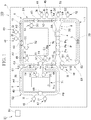
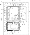
- FIG. 1 is a plan view for schematically showing a fluidic device 100 of a first embodiment.
- the fluidic device 100 of the present embodiment is a device for purifying and detecting a sample substance contained in a specimen sample.
- the sample substance is, for example, a biomolecule such as nucleic acid, DNA, RNA, a peptide, a protein, an extracellular vesicle and the like.
- the fluidic device 100 is provided with a substrate 9 on which a flow channel and a valve are formed.
- the flow channel formed in the substrate 9 of the fluidic device 100 is divided into a loop flow channel 1 which is formed in a closed loop shape, a first bypass flow channel 6 which bypasses a pair of connection portions 1a and 1b of the loop flow channel 1, and a second bypass flow channel 7 which bypasses a pair of connection portions 1c and 1d of the loop flow channel 1.
- a waste liquid tank 70 is provided inside the loop flow channel 1.
- a waste liquid tank 71 is provided inside the first bypass flow channel 6.
- the loop flow channel 1, the first bypass flow channel 6 and the second bypass flow channel 7 form a first circulation flow channel 10, a second circulation flow channel 20, a third circulation flow channel 30, and a fourth circulation flow channel 40. That is, the fluidic device 100 includes the first circulation flow channel 10, the second circulation flow channel 20, the third circulation flow channel 30, and the fourth circulation flow channel 40.
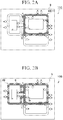
- FIG. 2A shows the first circulation flow channel 10 emphasized with a dot pattern.
- FIG. 2B shows the second circulation flow channel 20 emphasized with a dot pattern.
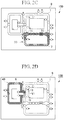
- FIG. 2C shows the third circulation flow channel 30 emphasized with a dot pattern.
- FIG. 2D shows the fourth circulation flow channel 40 emphasized with a dot pattern.
- the first circulation flow channel 10 is formed of the loop flow channel 1. That is, the first circulation flow channel 10 includes the entire loop flow channel 1.
- the second circulation flow channel 20 is formed with a portion of the loop flow channel 1 and the first bypass flow channel 6.
- the portion of the loop flow channel 1 included in the second circulation flow channel 20 is one flow channel having a long distance among two flow channels divided by the pair of connection portions 1a and 1b in the loop flow channel 1.
- the third circulation flow channel 30 is formed with a portion of the loop flow channel 1 and the second bypass flow channel 7.
- the portion of the loop flow channel 1 included in the third circulation flow channel 30 is one flow channel having a short distance among two flow channels divided by the pair of connection sections 1c and 1d in the loop flow channel 1.
- the fourth circulation flow channel 40 is formed with a portion of the loop flow channel 1 and the first bypass flow channel 6.
- the portion of the loop flow channel 1 included in the fourth circulation flow channel 40 is a partial flow channel 11 of the loop flow channel 1 which is not included in the second circulation flow channel 20 and the third circulation flow channel 30.
- the partial flow channel 11 is one flow channel having a short span among the two flow channels divided by the pair of connection sections 1a and 1b to which the first bypass flow channel 6 is connected in the loop flow channel 1.
- the fourth circulation flow channel 40 shares the first bypass flow channel 6 with the second circulation flow channel 20.
- the fourth circulation flow channel 40 is not used as a single body for circulating a liquid, and is mainly used to quantify a solution.
- the fourth circulation flow channel 40 is provided to circulate and mix solutions in both circulation flow channels of the first circulation flow channel 10 and the fourth circulation flow channel 40 after quantifying and circulating a solution in the first circulation flow channel.
- the first circulation flow channel 10 and the fourth circulation flow channel 40 are connected to form a second circulation flow channel 20.
- the valve V1 may be disposed between the connection portions 1a and 1b (the short one, that is, the partial flow channel 11) in the loop flow channel 1, and may be closed when a liquid is circulated in the second circulation flow channel 20. In this way, the liquid can flow in the second circulation flow channel in one direction.
- the fourth circulation flow channel 40 may be configured as a single body to circulate the liquid.
- the first circulation flow channel 10 and the fourth circulation flow channel 40 form a second continuous circulation flow channel (a second type continuous circulation flow channel) S2.
- the second circulation flow channel 20 and the third circulation flow channel 30 have a shared flow channel (a second shared flow channel 2B).
- the second circulation flow channel 20 and the third circulation flow channel 30 are configured to be able to circulate a solution in the third circulation flow channel 30 after the circulating the solution in the second circulation flow channel 20.
- the second circulation flow channel 20 and the third circulation flow channel 30 form a first continuous circulation flow channel (a first type continuous circulation flow channel) S1.
- the first circulation flow channel 10 and the second circulation flow channel 20 have a first shared flow channel 2A shared with each other.
- the first circulation flow channel 10 and the third circulation flow channel 30 have a shared flow channel (the second shared flow channel 2B).
- the first shared flow channel 2A and the second shared flow channel 2B share at least a portion of the flow channels (an overlapping shared flow channel 2).
- the entire length of the second shared flow channel 2B overlaps the entire length of the overlapping shared flow channel 2.
- a continuous circulation flow channel is divided into the first type continuous circulation flow channel and the second type continuous circulation flow channel.
- the first type continuous circulation flow channel is formed with two circulation flow channels and is configured to be able to circulate a solution in one circulation flow channel and then circulate the solution in the other circulation flow channel.
- the second type continuous circulation flow channel is formed with two circulation flow channels and is configured to be able to circulate a solution in one circulation flow channel and then circulate and mix solutions in both circulation flow channels.
- the other flow channel in the second type continuous circulation flow channel may be sufficient as long as it can circulate both the liquid contained therein and the liquid contained in the one circulation flow channel together, and may not be configured to circulate a liquid independently.
- the fluidic device of the present embodiment includes at least two continuous circulation flow channels selected from the group consisting of the first type continuous circulation flow channel and the second kind continuous circulation flow channel. Therefore, when the fluidic device of the present embodiment includes two continuous circulation flow channels, it may be any one of one including two first type continuous circulation flow channels, one including two second type continuous circulation flow channels, and one including each of the first type continuous circulation flow channel and the second type continuous circulation flow channel. When the fluidic device of the present embodiment includes three or more continuous circulation flow channels, all of them may be the first type continuous circulation flow channels or the second type continuous circulation flow channels, or they may include both of the first type and second type continuous circulation flow channels.
- two or more continuous circulation flow channels may share a circulation flow channel.
- the fluidic device of the present embodiment includes the first type continuous circulation flow channel and the second type continuous circulation flow channel
- one circulation flow channel of the first type continuous circulation flow channel may be used as one circulation flow channel of the second type continuous circulation flow channel.
- the first continuous circulation flow channel S1 is formed of two circulation flow channels (the second circulation flow channel 20 and the third circulation flow channel 30). Further, the first continuous circulation flow channel S 1 is configured to circulate a solution in one circulation flow channel (the second circulation flow channel 20) and then circulate the solution in the other circulation flow channel (the third circulation flow channel 30). Therefore, the first continuous circulation flow channel S 1 is classified as the first type continuous circulation flow channel.
- the two circulation flow channels (the second circulation flow channel 20 and the third circulation flow channel 30) in the first continuous circulation flow channel S1 share a portion of the flow channels (the second shared flow channel 2B).
- the second continuous circulation flow channel S2 is formed of two circulation flow channels (the first circulation flow channel 10 and the fourth circulation flow channel 40).
- the second continuous circulation flow channel S2 is configured to circulate a solution in one circulation flow channel (the first circulation flow channel 10), and then circulate and mix solutions in both circulation flow channels (that is, the second circulation flow channel 20) of the first circulation flow channel 10 and the fourth circulation flow channel 40. Therefore, the second continuous circulation flow channel S2 is classified as the second type continuous circulation flow channel.
- the first circulation flow channel 10 is provided with a plurality of valves V1, V2, V3, V4 and V5.
- the valves V1, V2 and V3 function as quantitative valves
- the valves V4 and V5 function as shared flow channel terminal valves which partition the overlapping shared flow channel 2 from other areas.
- a capturing section 4 and a pump P are disposed.
- the quantitative valves V1, V2 and V3 divide the first circulation flow channel 10 into a first quantitative section A1, a second quantitative section A2, and a third quantitative section A3. That is, the quantitative valves V1, V2 and V3 are arranged such that each of the sections of the first circulation flow channel 10 delimited by the quantitative valves has a predetermined volume. More specifically, the first quantitative section A1 is formed between the quantitative valves V1 and V2. The second quantitative section A2 is formed between the quantitative valves V2 and V3. The third quantitative section A3 is formed between the quantitative valves V1 and V3.
- An introduction flow channel 41, a discharge flow channel 52, and an air flow channel 61 are connected to the first quantitative section A1 of the first circulation flow channel 10.
- Introduction flow channels 42 and 43 and a discharge flow channel 53 are connected to the second quantitative section A2.
- Introduction flow channels 44, 45 and 48, a discharge flow channel 51, and a discharge flow channel (a recovery flow channel) 56 are connected to the third quantitative section A3.
- the introduction flow channel 48 and the discharge flow channel 56 are disposed at both ends of the overlapping shared flow channel 2 in the third quantitative section A3.
- the shared flow channel terminal valves V4 and V5 partition the first circulation flow channel 10 into the overlapping shared flow channel 2 and other areas.
- the shared flow channel terminal valves V4 and V5 are positioned at both ends of the overlapping shared flow channel 2 in the first circulation flow channel 10.
- the shared flow channel terminal valves V4 and V5 are positioned together in the third quantitative section A3.
- the entire area of the overlapping shared flow channel 2 is included in the third quantitative section A 3 of the first circulation flow channel 10.
- the second circulation flow channel 20 has the first shared flow channel 2A which is shared with the first circulation flow channel 10, and the first bypass flow channel 6 which is not shared with the first circulation flow channel 10.
- the plurality of valves V1, V2, V3, V4 and V5 described above are provided in the first shared flow channel 2A.
- a portion of the first shared flow channel 2A overlaps the overlapping shared flow channel 2. Therefore, the first shared flow channel 2A has the capturing section 4 and the pump P.
- the introduction flow channels 41, 42, 43, 44, 45 and 48, the discharge flow channels 51, 52, 53 and 56 and the air flow channel 61 are connected to the first shared flow channel 2A.
- the first bypass flow channel 6 is provided with a plurality of valves V6, V7 and V8.
- the valves V6 and V7 are positioned at terminals of the first bypass flow channel 6 and function as first bypass flow channel terminal valves which partition the first bypass flow channel 6 and the first shared flow channel 2A.
- the valve V8 functions as a quantitative valve.
- the quantitative valve V8 partitions the first bypass flow channel 6 into two regions of a predetermined volume.
- a fourth quantitative section A4 is formed between the quantitative valve V8 and the first bypass flow channel terminal valve V6.
- a fifth quantitative section A5 is formed between the quantitative valve V8 and the first bypass flow channel terminal valve V7.
- An introduction flow channel 46 and a discharge flow channel 54 are connected to the vicinities of both ends of the fourth quantitative section A4.
- an introduction flow channel 47 and a discharge flow channel 55 are connected to the vicinities of both ends of the fifth quantitative section A5.
- the third circulation flow channel 30 has a second shared flow channel 2B shared with the first circulation flow channel 10 and the second bypass flow channel 7 not shared with the first circulation flow channel 10.
- valves V9 and V10 are provided at both ends of the second shared flow channel 2B in the third circulation flow channel 30.
- the valves V9 and V10 function as shared flow channel terminal valves. That is, the shared flow channel terminal valves V9 and V10 partition the third circulation flow channel 30 into the second shared flow channel 2B and the second bypass flow channel 7.
- Air flow channels 62 and 63 are connected to the vicinities of both ends of the second bypass flow channel 7.
- a detecting section 3 is provided in the second bypass flow channel 7.
- the pump P is formed of three pump valves Pa, Pb, and Pc arranged side by side in the flow channel.
- the pump P can convey the liquid in the circulation flow channel by sequentially opening and closing the three pump valves Pa, Pb, and Pc.
- the number of valves constituting the pump valve may be 4 or more.
- the pump P circulates the liquid in the first circulation flow channel 10, the second circulation flow channel 20, and the third circulation flow channel 30.
- the flow velocity of the liquid circulating in the first circulation flow channel 10, the second circulation flow channel 20, and the third circulation flow channel 30 becomes slow near the wall surface of the flow channels due to the interaction (friction) between the wall surface of the flow channels and the solution in the flow channels and becomes faster in the center of the flow channels.
- distribution of the liquid flow velocity is generated, so that mixing of the solution is promoted. That is, driving the pump P creates convection in the liquid in the first circulation flow channel 10, so that mixing of a plurality of liquids is promoted.
- the capturing section 4 captures and collects the sample substance in the solution circulating in the first circulation flow channel 10.
- the capturing section 4 may capture carrier particles bound to the sample substance. By capturing the sample substance itself or carrier particles bound to the sample substance, the capturing section 4 can recover the sample substance from the liquid circulating in the first circulation flow channel 10.
- the fluidic device 100 can effectively concentrate, wash, and transport sample substances when the capturing section 4 is provided.
- a magnetic force generation source such as a magnet or the like can be disposed in the vicinity thereof.
- the carrier particles can be captured due to the magnetic force.
- a column having a filler capable of binding to carrier particles, an electrode capable of attracting carrier particles, etc. may be included.
- the capturing section 4 may be a nucleic acid array in which nucleic acids hybridizing with the nucleic acid are immobilized.
- an antibody array in which an antibody against the antigen is immobilized may be used.
- Carrier particles are, for example, particles that can react with the sample substance.
- the reaction between the carrier particles and the sample substance can be exemplified by, for example, a combination of a carrier particle and a sample substance, adsorption between a carrier particle and a sample substance, a modification of a carrier particle by a sample substance, a chemical change of a carrier particle by a sample substance, etc.
- carrier particles magnetic beads, magnetic particles, gold nanoparticles, agarose beads, plastic beads, etc., may be included.
- carrier particles having, on the surface thereof, a substance capable of binding or adsorbing to the sample substance may be used.
- a carrier particle having on its surface an antibody capable of binding to the protein it is possible to bind the antibody on the surface of the carrier particle and the protein.
- the substance capable of binding to the sample substance may be appropriately selected according to the type of the sample substance.
- a biotin-binding protein/biotin such as avidin and streptavidin
- an active ester group such as a succinimidyl group/amino group, an acetyl iodide group/amino group, a maleimide group/thiol group (-SH), a maltose-binding protein/maltose, a G protein/guanine nucleotide, polyhistidine peptide/metal ions of nickel, cobalt, or the like, glutathione-S-transferase/glutathione, a DNA-binding protein/DNA, an antibody/antigen molecule (epitope), calmodulin/a calmodulin-binding peptide, an ATP-binding protein/ATP, or various receptor protein/ligands thereof such as an estradiol receptor
- the carrier particles and the sample substance may react in the first circulation flow channel 10.
- a complex in which the carrier particles and the sample substance are combined is formed.
- mixing makes it possible to increase the collision frequency to improve the coupling reaction speed between them. This technique is suitable, for example, for immunoassays in which measurement of single items is common.
- the magnetic force of the capturing section 4 can preferably be controllable. Capture and release of the carrier particles can be controlled by controlling the magnetic force of the magnetic force generation source applied to the carrier particles. That is, the capturing section 4 is configured to be able to control the affinity for carrier particles. For example, the capturing section 4 may control the magnetic force applied to the carrier particles by changing the distance between the magnet and the circulation type flow channel. When the carrier particles become free from the captured state, the carrier particles are dispersed in the solution again. In the case of using an electromagnet as the capturing section 4, the magnetic force may be controlled by ON/OFF of the current and control of the current value to capture and release the carrier particles by the capturing section 4.
- the capturing section 4 may be an array in which carrier particles can be arranged.
- the region where the carrier particles can be captured may be well-shaped.
- the size of the wells may be 1 to 2 times the diameter of the carrier particles so that the carrier particles are contained one by one.
- a capturing means may be a magnet array in which a plurality of magnets are arranged in an array.
- a sample substance binding to carrier particles may be analyzed with the carrier particles captured. By arraying and capturing the carrier particles, the analysis of the sample substance binding to the carrier particles becomes more efficient.
- the detecting section 3 is provided for detecting a sample substance.
- the term "detecting a sample substance" is used in a sense that also includes indirectly detecting a sample substance.
- the sample substance may be combined with a detection assisting substance that assists with the detection of the sample substance.
- a detection assisting substance a labeling substance can be used.
- the labeling substance for example, fluorescent dyes, fluorescent beads, fluorescent proteins, quantum dots, gold nanoparticles, biotin, antibodies, antigens, energy absorbing substances, radioisotopes, chemiluminescent substances, enzymes, and the like can be employed.
- fluorescent dyes carboxyfluorescein (FAM), 6-carboxy-4',5'-dicloro2',7'-dimethoxyfluorescein (JOE), fluorescein isothiocyanate (FITC), tetrachlorofluorescein (TET), 5'-hexachloro-fluorescein-CEphosphoroamidite (HEX), Cy3, Cy5, Alexa568, Alexa647, and the like can be employed.
- FAM carboxyfluorescein
- JE 6-carboxy-4',5'-dicloro2',7'-dimethoxyfluorescein
- FITC fluorescein isothiocyanate
- TET tetrachlorofluorescein
- HEX 5'-hexachloro-fluorescein-CEphosphoroamidite
- Cy3, Cy5, Alexa568, Alexa647, and the like can be employed.
- alkaline phosphatase As the enzymes, alkaline phosphatase, peroxidase, and the like can be employed.
- the detecting section 3 can detect the sample substance by detecting the labeling substance mentioned above.
- the detecting section 3 may optically detect the sample substance, and can have a configuration, for example, in which an object lens or an imaging unit can be disposed in the vicinity thereof.
- the imaging unit may have, for example, an electron multiplying charge coupled device (EMCCD) camera.
- EMCCD electron multiplying charge coupled device
- the detecting section 3 may electrochemically detect the sample substance, and can have a configuration, for example, in which an electrode can be disposed in the vicinity thereof.
- the detecting section 3 may be provided together with the capturing section 4 capable of capturing the sample substance. By arranging the detecting section 3 toward the capturing section 4, the sample substance captured by the capturing section 4 can be efficiently detected.
- the introduction flow channels 41 to 48 are provided for introducing different liquids into the first circulation flow channel 10, the second circulation flow channel 20, or the third circulation flow channel 30.
- the introduction flow channels 41 to 48 are provided with introduction flow channel valves I1 to I8 for opening and closing the introduction flow channels, respectively. Also, at ends of the introduction flow channels 41 to 48, liquid introduction inlets which are opened on a surface of the substrate 9 are provided.
- the introduction flow channels 41 to 48 are disposed in the vicinities of the valves (the quantitative valves) for partitioning the regions into which the liquid is introduced.
- the valves the quantitative valves
- the air in the flow channel is pushed out by the liquid and the air is discharged from the air flow channel which is not shown.
- the quantitative valve and the introduction flow channel are separated from each other, the air between the quantitative valve and the introduction flow channel is not discharged and air pockets are easily generated, and therefore, there is a possibility that the liquid will not fill up to the quantitative valve.
- the discharge flow channels 51 to 56 are provided to discharge the liquid from the first circulation flow channel 10, the second circulation flow channel 20, or the third circulation flow channel 30.
- the discharge flow channels 51 to 56 are provided with discharge flow channel valves O1 to O6 for opening and closing the discharge flow channels, respectively.
- the discharge flow channel 56 connected to one end of the overlapping shared flow channel 2 functions as a recovery flow channel for collecting the reacted liquid. Therefore, a recovery tank (not shown) is connected to the terminal of the discharge flow channel (recovery flow channel) 56.
- the other discharge flow channels 51 to 55 are connected to the waste liquid tank 70 or the waste liquid tank 71.
- the waste liquid tanks 70 and 71 are provided with outlets 70a and 71a which are connected to an external suction pump (not shown) and are opened on the surface of the substrate for negative pressure suction.
- the waste liquid tank 70 is disposed in an inside region of the loop flow channel 1
- the waste liquid tank 71 is disposed in an inside region of the first bypass flow channel 6. This makes it possible to reduce the size of the fluidic device 100.
- the discharge flow channels 51 to 56 are arranged near the quantitative valves. This makes it possible to suppress the residual liquid at the time of discharge by disposing the discharge flow channels 51 to 56 in the vicinities of the quantitative valves.
- the air flow channels 61 to 63 are provided to introduce or discharge air from the first circulation flow channel 10.
- the air flow channels 61 to 63 are provided with air flow channel valves G1, G2 and G3 for opening and closing the flow channels.
- Air introduction inlets which are opened on the surface of the substrate 9 are provided at ends of the air flow channels 61 to 63.
- the air flow channel 63 functions as an air discharge flow channel for sucking air out.
- the other air flow channels 61 and 62 function as air introduction flow channels for introducing air into the flow channels to push out the liquid in the flow channels.
- the nucleic acid can be purified and detected from a specimen liquid such as blood or the like.
- the quantitative valves V1, V2, and V3 of the first circulation flow channel 10 the valves V6 and V7 positioned at the ends of the first bypass flow channel 6, and the valves V9 and V10 positioned at the ends of the second bypass flow channel 7 are closed.
- the first circulation flow channel 10 is comparted into the first quantitative section A1, the second quantitative section A2, and the third quantitative section A3.
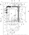
- a specimen liquid (solution) L1 containing a sample substance is introduced from the introduction flow channel 41 into the first quantitative section A1
- a first reagent liquid L2 is introduced from the introduction flow channel 42 into the second quantitative section A2
- a second reagent liquid (pretreatment solution) L3 is introduced from the introduction flow channel 44 into the third quantitative section A3. That is, the solution (specimen liquid L1) containing the sample substance, the first reagent liquid L2 and the second reagent liquid L3 are introduced into the circulation flow channel (the first circulation flow channel 10) ahead of the second continuous circulation flow channel S2. Also, the first reagent liquid L2 and the second reagent liquid L3 may be filled beforehand in the second quantitative section A2 and the third quantitative section A3, respectively.
- the specimen liquid L1 is blood, serum or plasma, and contains nucleic acids as the sample substance.
- the first reagent liquid L2 is, for example, a solution of proteinase K.
- Proteinase K inactivates enzymes that degrade nucleic acids (nucleases). Thus, it is possible to suppress the decomposition of the nucleic acid extracted from the specimen liquid L1 by the action of the enzyme.
- the second reagent liquid L3 is a cell lysis solution for extracting nucleic acid from blood, serum or plasma contained in the specimen liquid L1.
- the valves V1, V2, and V3 are opened to make the first circulation flow channel 10 a continuous loop, and then the pump P is driven to circulate and mix the specimen liquid L1, the first reagent liquid L2, and the second reagent liquid L3 in the first circulation flow channel 10, thereby obtaining a first mixed solution L4.
- the pump P is driven to circulate and mix the specimen liquid L1, the first reagent liquid L2, and the second reagent liquid L3 in the first circulation flow channel 10, thereby obtaining a first mixed solution L4.
- the nucleic acid is extracted as the sample substance.
- V6, V7, and V8 in the second circulation flow channel 20 are closed, and the second circulation flow channel 20 is comparted into the fourth quantitative section A4 and the fifth quantitative section A5.
- a third reagent liquid (solution) L5 containing carrier particles is introduced from the introduction flow channel 46 into the fourth quantitative section A4, and a fourth reagent liquid L6 is introduced from the introduction flow channel 47 into the fifth quantitative section A5.
- this step can be referred to as the step of introducing the third reagent liquid L5 and the fourth reagent liquid L6 into the fourth circulation flow channel 40.
- the third reagent liquid L5 and the fourth reagent liquid L6 may be filled in advance in the fourth quantitative section A4 and the fifth quantitative section A5, respectively.
- magnetic particles e.g., silica magnetic particles
- the silica magnetic particles bind (adsorb) to the nucleic acid (sample substance) in alcohol.
- the fourth reagent liquid L6 is, for example, an isopropanol solution.
- Isopropanol creates an alcoholic environment to form an environment in which the magnetic particles can bind to the nucleic acid.
- the valves V6, V7, and V8 are opened and the valve V1 is closed to make the second circulation flow channel 20 a continuous loop, and then the pump P is driven.
- the first mixed solution L4 in the first circulation flow channel 10 the third reagent liquid L5, and the fourth reagent liquid L6 are circulated and mixed to obtain a second mixed solution L7.
- the magnetic particles (carrier particles) bind to the nucleic acid (sample substance) contained in the first mixed solution L4, and a complex of the sample substance and the carrier particles is produced.
- this step can be referred to as a step in which the solutions in both circulation flow channels of the first circulation flow channel 10 and the fourth circulation flow channel 40 (i.e., the second circulation flow channel) in the second continuous circulation flow channel S2 are mixed to obtain a second mixed solution L7.
- a magnet for capturing the magnetic particles in the capturing section 4 is brought close to the flow channel while the second mixed solution L7 is circulated in the second circulation flow channel 20.
- the capturing section 4 captures the complex of the sample substance and the carrier particles.
- the complex of the sample substance and the carrier particles is trapped on an inner wall surface of the flow channel of the capturing section 4.
- the valves V1 and V6 are closed and the valve G1 of the air flow channel 61 is opened to open the valve O4 of the discharge flow channel 54.
- the liquid component (waste liquid) separated from the complex is discharged from the second circulation flow channel to the waste liquid tank 71.
- the second mixed solution L7 is removed from the flow channel (overlapping shared flow channel 2) shared by the second continuous circulation flow channel S2 and the third circulation flow channel 30, and the complex of the sample substance and carrier particles captured in the capturing section 4 is separated from the liquid component.
- the valves V6 and V7 are closed to make the first circulation flow channel 10 a continuous loop, and then a cleaning liquid is introduced from the introduction flow channel 43 or the introduction flow channel 45 to fill the first circulation flow channel 10. Also, by driving the pump P, the cleaning liquid is circulated in the first circulation flow channel 10 and cleans the complex of the nucleic acid and magnetic particles captured in the capturing section 4. Further, after the circulation of the cleaning liquid for a predetermined period of time is completed, the cleaning liquid is discharged to the waste liquid tank 70.
- the cycle of introduction, circulation and discharge of the cleaning liquid may be performed multiple times. By repeating the introduction, circulation and discharge of the cleaning liquid, the removal efficiency of unnecessary matters can be increased.
- the cleaning liquid may be circulated in the second circulation flow channel 20 for cleaning.
- a fifth reagent liquid (solution for detection) L8 containing an eluate and a labeling substance (detection assisting substance) is introduced from the introduction flow channel 48 to fill the third circulation flow channel 30 with the fifth reagent liquid L8.
- the eluate contained in the fifth reagent liquid L8 is, for example, water.
- the silica magnetic particles bind to nucleic acids in alcohol, but not in water.
- the fifth reagent liquid L8 includes the labeling substance that binds to the nucleic acid (sample substance) and assists with the detection in the detecting section. Also, the fifth reagent liquid L8 may be a solution suitable for storage of nucleic acid.
- the fifth reagent liquid L8 is circulated in the third circulation flow channel 30 by driving the pump P with the complex of the nucleic acid and the magnetic particles released or not released in the capturing section 4.
- the nucleic acid is eluted from the complex of the nucleic acid and the magnetic particles and the labeling substance binds to the nucleic acid, thereby producing a complex of the sample substance and the labeling substance.
- capturing is started again by the capturing section 4 as a next step, and the magnetic particles are captured again. In this way, the magnetic particles can be removed from the liquid, leaving only the nucleic acid bound to the labeling substance in the solution.
- the nucleic acid can be purified through the above steps.
- a solution containing only nucleic acid in water can be purified.
- the purified solution can be recovered from the discharge flow channel (recovery flow channel) 56.
- the detection section 3 can detect the nucleic acid by detecting the reaction product such as a dye, fluorescence, or the like created by the reaction with the substrate using the detecting section 3.
- the flow directions of the solution in the overlapping shared flow channel 2 when the solution is circulated in each of the first to third circulation flow channels 10, 20 and 30 may be identical or opposite to each other.
- the term “circulate” means not only a case where a fluid flows in one direction but also a case where the fluid reciprocates in a circulation flow channel at a constant cycle.
- the fluidic device 100 of the present embodiment includes the first continuous circulation flow channel S1 formed with two continuous circulation flow channels (the second circulation flow channel 20 and the third circulation flow channel 30) which share a portion of the flow channels (the second shared flow channel 2B).
- the first continuous circulation flow channel S1 is configured such that the solution is circulated in the preceding circulation flow channel (the second circulation flow channel 20) and then circulated in the subsequent circulation flow channel (the third circulation flow channel 30). Since the first continuous circulation flow channel S1 has the second shared flow channel 2B in the preceding circulation flow channel and the subsequent circulation flow channel, at least part of the liquid which is circulated and mixed in the preceding circulation flow channel can be circulated in the subsequent circulation flow channel without going through a transferring process.
- the fluidic device 100 of the present embodiment includes the second continuous circulation flow channel S2 formed with two continuous circulation flow channels (the first circulation flow channel 10 and the fourth circulation flow channel 40).
- the second continuous circulation flow channel S2 is configured such that the solution is circulated in the preceding circulation flow channel (the first circulation flow channel 10), and then the solutions in both circulation flow channels (the first circulation flow channel 10 and the fourth circulation flow channel 40) can be circulated and mixed.
- the solution in the fourth circulation flow channel 40 can be further added, circulated, and mixed.
- the two circulation flow channels form the second circulation flow channel 20.
- the two continuous circulation flow channels S1 and S2 circulate the solution in the order of the second continuous circulation flow channel S2 and the first continuous circulation flow channel S1.
- the subsequent circulation flow channel (the second circulation flow channel 20) of the preceding continuous circulation flow channel (the second continuous circulation flow channel S2) is also used as a preceding circulation flow channel of the subsequent continuous circulation flow channel (the first continuous circulation flow channel S1).
- the sample substance is sequentially conveyed into a plurality of three or more circulation flow channels (the first circulation flow channel 10, the second circulation flow channel 20, and the third circulation flow channel 30), so that pretreatment and purification or detection can be carried out continuously in each circulation flow channel.
- the fluidic device 100 of the present embodiment includes the first continuous circulation flow channel S1 and the second continuous circulation flow channel S2, sequential reactions which require quantitation and mixing of the liquid can be performed sequentially in one device.
- the order in which the liquid is circulated in the first continuous circulation flow channel S1 and the second continuous circulation flow channel S2 may be opposite to the order shown in the embodiment.
- the present embodiment has illustrated the case where the fluidic device 100 includes a total of two continuous circulation flow channels, i.e., two types of continuous circulation flow channels one by one, it may include three or more, and may further include a flow channel (for example, a straight flow channel) other than the circulation flow channel.
- the second circulation flow channel 20 and the third circulation flow channel 30 constituting the first continuous circulation flow channel S1 share the capturing section 4 in the second shared flow channel 2B. Therefore, the sample substance to which carrier particles generated by circulation in the second circulation flow channel 20 are bound can be captured in the capturing section 4, and condensed to be carried to the third circulation flow channel 30.
- the pump P is disposed in the flow channel (that is, the overlapping shared flow channel 2) shared by all of the circulation flow channels of the first continuous circulation flow channel S1 (the first circulation flow channel 10 and the second circulation flow channel 20) and by all of the circulation flow channels (the second circulation flow channel 20 and the third circulation flow channel 30) among the second continuous circulation flow channel S2, in which liquids are circulated.
- circulation of the liquids in all the circulation flow channels of the first and second continuous circulation flow channels S1 and S2 can be performed by driving one pump P. That is, according to the present embodiment, it is possible to provide an inexpensive fluidic device 100 with a simple structure by reducing the number of pumps mounted on the fluidic device 100.
- the first continuous circulation flow channel S1 has the detecting section 3 for detecting the sample substance disposed in the flow channel (the second bypass flow channel 7) that is not shared with the preceding circulation flow channel (the second circulation flow channel 20) in the subsequent circulation flow channel (the third circulation flow channel 30).
- the detecting section 3 is provided in the second bypass flow channel 7, it is possible to perform the detection in a flow channel in which no foreign matter remains, thereby reducing the influence of the background noise and improving the detection accuracy.
- the fluidic device 100 of the present embodiment has the quantitative valves V1, V2, V3 and V8 provided in the first circulation flow channel 10 and the fourth circulation flow channel 40. This makes it possible to quantify the liquids in the first circulation flow channel 10 and the fourth circulation flow channel 40. Further, according to the present embodiment, since continuous loops can be formed by opening the quantitative valves V1, V2 and V8, it is possible to circulate and efficiently mix the liquids quantified in the circulation flow channels, thereby accelerating the reaction.
- any one of the pump valves Pa, Pb and Pc constituting the pump P can be used as a quantitative valve for quantifying the solution.
- the third quantitative section A3 can be further divided into two sections. In this case, a different solution can be quantified in each of the partitioned sections of the third quantitative section A3.
- the pump valves Pa, Pb and Pc are used as the quantitative valve, these are provided in the overlapping shared flow channel 2. Accordingly, various compartment areas can be formed with a small number of valves and various quantitative measurements can be performed.
- At least one introduction flow channel and discharge flow channel are provided in all of the sections (the first to fifth quantitative sections A1, A2, A3, A4 and A5) of the circulation flow channels partitioned by the quantitative valves.
- a system 91 includes the fluidic device 100 and a control unit 90.
- the control unit 90 is connected to the valves provided in the fluidic device 100 via a connection line (not shown), and controls opening and closing of the valves.
- the mixing, capturing and detecting in the fluidic device 100 can be performed.
- the present modification is mainly different from the first embodiment in that a second detecting section 3A (the two-dotted chain line in FIG. 1 ) is additionally provided together with the capturing section 4.
- the second detecting section 3A is disposed to overlap the capturing section 4.
- the second detecting section 3A is provided for detecting a sample substance.
- the second detecting section 3A is provided to detect a sample substance which is different from that detected by the detecting section 3 (hereinafter, the first detecting section 3) of the second bypass flow channel 7.
- the first detecting section 3 is used as a detecting section that detects a sample substance susceptible to background noise.
- the second detecting section 3A can be preferably used as a detecting section that detects a sample substance that is not easily influenced by background noise.
- the second mixed solution L7 ( FIG. 6 ) is discharged and the complex of the sample substance and the carrier particles captured by the capturing section 4 is separated from the liquid component. Then, a solution for detecting the sample substance is introduced into the second circulation flow channel 20 and circulated, so that the detection can be carried out in the second detecting section 3A.
- the second detecting section 3A may detect the sample substance in a state in which the sample substance is released from the capturing section 4, and the sample substance may be detected without being released from the capturing section 4.
- FIG. 8 is a plan view for schematically showing a fluidic device 200 according to a second embodiment.
- the fluidic device 200 of the second embodiment is different from the first embodiment mainly in that it has three continuous circulation flow channels S1, S2 and S3. Also, the same constituent elements as those in the embodiments described above will be denoted by the same reference numerals and the description thereon will be omitted.
- the fluidic device 200 of the present embodiment further includes a third bypass flow channel 108 in addition to the loop flow channel 1, the first bypass flow channel 6 and the second bypass flow channel 7.
- the third bypass flow channel 108 connects and bypasses the pair of connection portions 7a and 7b of the second bypass flow channel 7.
- a second capturing section 104 is provided in the flow channel of the third bypass flow channel 108.
- the second capturing section 104 also serves as a detecting section 103.
- the loop flow channel 1, the first bypass flow channel 6, the second bypass flow channel 7, and the third bypass flow channel 108 form the first circulation flow channel 10, the second circulation flow channel 20, the third circulation flow channel 30, the fourth A circulation flow channel 40, a fifth circulation flow channel 150, and a sixth circulation flow channel 160.
- the first to fourth circulation flow channels 10, 20, 30 and 40 have the same configuration as in the first embodiment.
- Each of the fifth circulation flow channel 150 and the sixth circulation flow channel 160 includes a portion of the third circulation flow channel 30 and the third bypass flow channel 108.
- the portion of the third circulation flow channel 30 included in the fifth circulation flow channel 150 and the portion of the third circulation flow channel 30 included in the sixth circulation flow channel 160 are different from each other.
- the portion of the third circulation flow channel 30 included in the fifth circulation flow channel 150 is one flow channel having a long distance among the two flow channels divided by the pair of connection portions 7a and 7b.
- the portion of the third circulation flow channel 30 included in the sixth circulation flow channel 160 is one flow channel having a short distance among the two flow channels divided by the pair of connection portions 7a and 7b.
- the sixth circulation flow channel 160 is mainly used for quantifying a solution.
- the sixth circulation flow channel 160 is not used as a single body for circulating a liquid.
- the sixth circulation flow channel 160 may be configured to be used as a single body for circulating the liquid.
- the sixth circulation flow channel 160 is provided to circulate a solution in the third circulation flow channel, and then circulate and mix solutions in both circulation flow channels of the third circulation flow channel 30 and the sixth circulation flow channel 160.
- the third circulation flow channel 30 and the sixth circulation flow channel 160 are connected to each other to form the fifth circulation flow channel 150.
- a valve may be disposed between the connection portions 1a and 1b (the short one) in the third circulation flow channel, and the valve may be closed when the liquid is circulated in the fifth circulation flow channel. In this way, it is possible to flow the liquid through the fifth circulation flow channel in one direction.
- the second circulation flow channel 20 and the third circulation flow channel 30 constitute the first continuous circulation flow channel S1.
- the first circulation flow channel 10 and the fourth circulation flow channel 40 constitute the second continuous circulation flow channel S2.
- the third circulation flow channel 30 and the sixth circulation flow channel 160 constitute a third continuous circulation flow channel (the second type continuous circulation flow channel) S3.
- the first continuous circulation flow channel S1 is classified as the first type continuous circulation flow channel
- the second continuous circulation flow channel S2 is classified as the second type continuous circulation flow channel.
- the third continuous circulation flow channel S3 is formed with two continuous circulation flow channels (the third circulation flow channel 30 and the sixth circulation flow channel 160).
- the third continuous circulation flow channel S3 is configured to circulate a solution in the preceding circulation flow channel (the third circulation flow channel 30), and then circulate and mix solutions in both circulation flow channels of the third circulation flow channel 30 and the sixth circulation flow channel 160 (that is, the fifth circulation flow channel 150). Therefore, the third continuous circulation flow channel S3 is classified into the second type continuous circulation flow channel.
- the second capturing section 104 of the present embodiment is a DNA microarray.
- the second capturing section 104 has a nucleic acid probe which is arranged in the flow channel and has a gene sequence that hybridizes complementarily to a sample substance (nucleic acid, particularly RNA in this embodiment).
- FIG. 9 is a schematic diagram of the second capturing section 104.
- a capturing probe 170 is formed in the second capturing section 104.
- the capturing probe 170 has a sequence which may hybridize with a nucleic acid to be detected.
- may hybridize means that a portion of the capturing probe 170 to be used hybridizes to a target nucleic acid (for example, a target RNA) under stringent conditions, and does not hybridize or is difficult to hybridize to a nucleic acid molecule other than the target nucleic acid.
- stringent conditions include, for example, the conditions described in Molecular Cloning-A LABORATORY MANUAL 2nd EDITION (Sambrook et al., Cold Spring Harbor Laboratory Press ).
- the capturing probe 170 has a first portion 171 and a spacer 174.
- the first portion 171 consists of a sequence which may hybridize with RNA.
- the spacer 174 is provided for the first portion 171 to secure molecular freedom for hybridization of RNA.
- the length of the spacer 174 is not particularly limited, for example, it is 3 bases to 50 bases, or 5 bases to 25 bases.
- the bases used for the spacer 174 can be substituted with a linker such as PEG and the like which has the same length and softness. In this case, the number of bases used for the spacer 174 may be 0 bases.
- the capturing probe 170 may be DNA or RNA. As long as it has the same function as DNA or RNA, it is not limited to natural and non-natural, and it may contain artificial nucleic acids such as peptide nucleic acid (PNA), locked nucleic acid (LNA), bridged nucleic acid (BNA), etc.
- the capturing probe 170 may also include LNA or BNA from the perspective that, compared to DNA and RNA, it has high affinity with the target RNA, is not easily recognized by DNA degrading enzymes and RNA degrading enzymes, and can be a substrate of DNA ligase such as T4 DNA ligase and the like.
- the second capturing section 104 also serves as the detecting section 103.
- a detection assisting substance (a labeling substance) for fluorescently labeling is bound to RNA to be detected is bound in advance.
- the RNA amount is estimated using the fluorescence intensity as an index. That is, the detecting section 103 indirectly detects RNA by detecting the detection assisting substance bound to RNA.
- a labeling substance for fluorescently labeling RNA can be employed as the detection assisting substance.
- the nucleic acid is purified by the same procedure as in the first embodiment. That is, in the first circulation flow channel 10, the specimen liquid and the pretreatment solution are circulated and RNA is extracted to obtain the first mixed solution. Next, in the second circulation flow channel 20, the second mixed solution and the solution containing carrier particles are circulated to obtain the second mixed solution containing the complex of RNA and the carrier particles. Further, while circulating the second mixed solution in the second circulation flow channel 20, the complex is captured in the capturing section 4 (hereinafter, the first capturing section 4). Subsequently, by removing the second mixed solution from the overlapping shared flow channel 2, the complex captured by the first capturing section 4 is separated from the liquid component. As a result, the complex remains in the overlapping shared flow channel 2.
- the cleaning liquid is introduced into the third circulation flow channel 30 and is circulated in the third circulation flow channel 30, so that the complex is washed.
- the valves positioned at both ends of the third bypass flow channel 108 are opened to make the fifth circulation flow channel 150 a continuous loop, and the solution for detection containing the eluate and the labeling substance (detection assisting substance) is circulated in the fifth circulation flow channel 150.
- the solution for detection containing the eluate and the labeling substance detection assisting substance
- RNA is hybridized to the capturing probe 170. Subsequently, after RNAnonspecifically absorbed on the substrate is washed, RNA can be detected by observing the second capturing section 104 to estimate the amount of RNA using the fluorescence intensity as an index.
- the detection target is RNA in the present embodiment
- other biomolecules for example, nucleic acids such as DNA, RNA, etc.
- nucleic acids such as DNA, RNA, etc.
- the three continuous circulation flow channels S1, S2 and S3 are configured to perform circulating through the second continuous circulation flow channel S2, then circulating through the first continuous circulation flow channel S1, and further circulating through the third continuous circulation flow channel S3. That is, the fluidic device 200 includes the second type continuous circulation flow channel, the first type continuous circulation flow channel, and the second type continuous circulation flow channel in this order.
- the subsequent circulation flow channel of the preceding continuous circulation flow channel is also used as the preceding circulation flow channel of the subsequent continuous circulation flow channel.
- pretreatment and purification or detection can be carried out continuously in each circulation flow channel.
- the fluidic device 200 of the present embodiment can sequentially perform more complicated sequential reactions requiring quantitation and mixing of liquids in one device.
Landscapes
- Chemical & Material Sciences (AREA)
- Life Sciences & Earth Sciences (AREA)
- Health & Medical Sciences (AREA)
- Engineering & Computer Science (AREA)
- General Health & Medical Sciences (AREA)
- Organic Chemistry (AREA)
- Biochemistry (AREA)
- Analytical Chemistry (AREA)
- Bioinformatics & Cheminformatics (AREA)
- Zoology (AREA)
- Wood Science & Technology (AREA)
- Physics & Mathematics (AREA)
- Immunology (AREA)
- Biotechnology (AREA)
- General Physics & Mathematics (AREA)
- Pathology (AREA)
- Chemical Kinetics & Catalysis (AREA)
- Microbiology (AREA)
- Genetics & Genomics (AREA)
- Proteomics, Peptides & Aminoacids (AREA)
- Computer Hardware Design (AREA)
- Microelectronics & Electronic Packaging (AREA)
- General Engineering & Computer Science (AREA)
- Medicinal Chemistry (AREA)
- Molecular Biology (AREA)
- Biomedical Technology (AREA)
- Sustainable Development (AREA)
- Biophysics (AREA)
- Dispersion Chemistry (AREA)
- Hematology (AREA)
- Clinical Laboratory Science (AREA)
- Automatic Analysis And Handling Materials Therefor (AREA)
- Apparatus Associated With Microorganisms And Enzymes (AREA)
Abstract
Description
- The present invention relates to a fluidic device, a system, and a method for detecting a sample substance.
- Priority is claimed on Japanese Unexamined Patent Application, First Publication No.
2016-112604 filed June 6, 2016 - In recent years, the development of Micro-Total Analysis Systems (µ-TAS) aiming at high-speed testing, high efficiency, and integration of testing in the field of in vitro diagnosis, or ultra-miniaturization of the testing equipment, etc., has attracted attention, and active studies are under way worldwide.
- µ-TAS is superior to conventional inspection equipment in that measurement and analysis can be performed with a small amount of a sample, portability and disposability can be realized at low cost, etc.
- Also, it has attracted attention as a method that is highly useful in the case of using expensive reagents or inspecting small amounts of many specimens.
- As a component of µ-TAS, a device including a loop-shaped flow channel and a pump arranged on the flow channel has been reported (Non Patent Document 1). In this device, by injecting a plurality of solutions into the loop-shaped flow channel and operating the pump, the plurality of solutions are mixed in the loop shaped flow channel.
- [Non Patent Document 1]
Jong Wook Hong, Vincent Studer, Giao Hang, W French Anderson and Stephen R Quake, Nature Biotechnology 22, 435-439 (2004) - In the field of in vitro diagnosis, especially point of care testing (POCT), it is necessary to perform multiple reactions continuously and in a short time with a small amount of a sample. The µ-TAS described in
Non Patent Document 1 failed to sufficiently solve this problem. - An aspect of the present invention is to provide a fluidic device which is low in cost, can easily perform an inspection procedure involving a plurality of reactions, and can shorten the inspection time.
- One embodiment of the present invention provides the following (1) to (4).
- (1) A fluidic device according to one embodiment of the present invention is a fluidic device for capturing or detecting a sample substance contained in a solution, which includes at least two continuous circulation flow channels selected from the group consisting of: a first type continuous circulation flow channel which is formed of a first circulation flow channel and a second circulation flow channel and which is configured to circulate the solution in the first circulation flow channel and then circulate the solution in the second circulation flow channel; and a second type continuous circulation flow channel which is formed of a third circulation flow channel and a fourth circulation flow channel and which is configured to circulate the solution in the third circulation flow channel and then circulate and mix the solution in both of the third and fourth circulation flow channels, wherein any one of the circulation flow channels has a capturing section which captures the sample substance, and/or a detecting section which detects the sample substance.
- (2) A system according to one embodiment of the present invention includes the fluidic device and a control unit for controlling opening and closing of a valve.
- (3) A fluidic device according to one embodiment of the present invention is a fluidic device for capturing or detecting a sample substance contained in a solution, which includes a first circulation flow channel, a second circulation flow channel, and a third circulation flow channel, wherein the first circulation flow channel and the second circulation flow channel share a first shared flow channel, the first circulation flow channel and the third circulation flow channel share a second shared flow channel, and the first shared flow channel or the second shared flow channel has a capturing section which captures the sample substance, and/or the first shared flow channel or the second shared flow channel has a detecting section which detects the sample substance.
- (4) A method for detecting a sample substance according to one embodiment of the present invention includes using a fluidic device including a continuous circulation flow channel which is formed of a first circulation flow channel and a second circulation flow channel and which is configured to circulate a solution in the first circulation flow channel and then circulate and mix solutions in both circulation flow channel of the first circulation flow channel and the second circulation flow channel, and a third circulation flow channel which shares at least a portion of the flow channel with the continuous circulation flow channel and which is configured to circulate the solution after circulating the solution in the continuous circulation flow channel, the fluidic device having a capturing section for capturing a sample substance at the flow channel shared by the continuous circulation flow channel and the third circulation flow channel, and further includes the steps of: introducing a solution containing the sample substance into the first circulation flow channel of the continuous circulation flow channel; obtaining a first mixed solution by circulating and mixing the solution containing the sample substance and a pretreatment solution in the first circulation flow channel of the continuous circulation flow channel; obtaining a second mixed solution containing a complex of the sample substance and a carrier particle by circulating the first mixed solution and a solution containing the carrier particle bound to the sample substance in both of the circulation flow channels of the continuous circulation flow channel; capturing the complex in the capturing section by further circulating the second mixed solution in the continuous circulation flow channel; removing the second mixed solution from a flow channel shared by the continuous circulation flow channel and the third circulation flow channel; and detecting the sample substance by circulating a detection solution in the third circulation flow channel while releasing or not releasing the sample substance or the complex from the capturing section.
-
-
FIG. 1 is a plan view for schematically showing a fluidic device according to a first embodiment. -
FIG. 2A is a plan view for schematically showing the fluidic device according to the first embodiment, in which a first circulation flow channel is emphasized. -
FIG. 2B is a plan view for schematically showing the fluidic device of the first embodiment, in which a second circulation flow channel is emphasized. -
FIG. 2C is a plan view for schematically showing the fluidic device of the first embodiment, in which a third circulation flow channel is emphasized. -
FIG. 2D is a plan view for schematically showing the fluidic device of the first embodiment, in which a fourth circulation flow channel is emphasized. -
FIG. 3 is a diagram for showing a step of introducing a specimen liquid, a first reagent liquid and a second reagent liquid into the first circulation flow channel in a purification method using the fluidic device of the first embodiment. -
FIG. 4 is a diagram for showing a step of obtaining a first mixed liquid by circulating and mixing the specimen liquid, the first reagent liquid and the second reagent liquid in the first circulation flow channel in the purification method using the fluidic device of the first embodiment. -
FIG. 5 is a diagram for showing a step of introducing a third reagent liquid and a fourth reagent liquid into a second circulation flow channel in the purification method using the fluidic device of the first embodiment. -
FIG. 6 is a diagram for showing a step of obtaining a second mixed solution by circulating and mixing the first mixed solution, the third reagent liquid and the fourth reagent liquid in the second circulation flow channel in the purification method using the fluidic device of the first embodiment. -
FIG. 7 is a diagram for showing a step of circulating a fifth reagent liquid in the second circulation flow channel in the purification method using the fluidic device of the first embodiment. -
FIG. 8 is a plan view for schematically showing a fluidic device according to a second embodiment. -
FIG. 9 is a schematic diagram for showing a capturing section used in the fluidic device according to the second embodiment. - Hereinafter, a fluidic device according to an embodiment will be described with reference to the drawings. In the drawings used in the following description, characteristic portions may be shown in an enlarged manner for the sake of convenience to make the features easier to understand, and the dimensional proportions of the components are not necessarily the same as the actual ones.
-
FIG. 1 is a plan view for schematically showing afluidic device 100 of a first embodiment. - The
fluidic device 100 of the present embodiment is a device for purifying and detecting a sample substance contained in a specimen sample. The sample substance is, for example, a biomolecule such as nucleic acid, DNA, RNA, a peptide, a protein, an extracellular vesicle and the like. Thefluidic device 100 is provided with asubstrate 9 on which a flow channel and a valve are formed. - The flow channel formed in the
substrate 9 of thefluidic device 100 is divided into aloop flow channel 1 which is formed in a closed loop shape, a firstbypass flow channel 6 which bypasses a pair ofconnection portions loop flow channel 1, and a secondbypass flow channel 7 which bypasses a pair ofconnection portions loop flow channel 1. Awaste liquid tank 70 is provided inside theloop flow channel 1. Awaste liquid tank 71 is provided inside the firstbypass flow channel 6. - The
loop flow channel 1, the firstbypass flow channel 6 and the secondbypass flow channel 7 form a firstcirculation flow channel 10, a secondcirculation flow channel 20, a thirdcirculation flow channel 30, and a fourthcirculation flow channel 40. That is, thefluidic device 100 includes the firstcirculation flow channel 10, the secondcirculation flow channel 20, the thirdcirculation flow channel 30, and the fourthcirculation flow channel 40. -
FIG. 2A shows the firstcirculation flow channel 10 emphasized with a dot pattern.FIG. 2B shows the secondcirculation flow channel 20 emphasized with a dot pattern.FIG. 2C shows the thirdcirculation flow channel 30 emphasized with a dot pattern.FIG. 2D shows the fourthcirculation flow channel 40 emphasized with a dot pattern. - As shown in
FIG. 2A , the firstcirculation flow channel 10 is formed of theloop flow channel 1. That is, the firstcirculation flow channel 10 includes the entireloop flow channel 1. - As shown in
FIG. 2B , the secondcirculation flow channel 20 is formed with a portion of theloop flow channel 1 and the firstbypass flow channel 6. In the present embodiment, the portion of theloop flow channel 1 included in the secondcirculation flow channel 20 is one flow channel having a long distance among two flow channels divided by the pair ofconnection portions loop flow channel 1. - As shown in
FIG. 2C , the thirdcirculation flow channel 30 is formed with a portion of theloop flow channel 1 and the secondbypass flow channel 7. In the present embodiment, the portion of theloop flow channel 1 included in the thirdcirculation flow channel 30 is one flow channel having a short distance among two flow channels divided by the pair ofconnection sections loop flow channel 1. - As shown in
FIG. 2D , the fourthcirculation flow channel 40 is formed with a portion of theloop flow channel 1 and the firstbypass flow channel 6. In the present embodiment, the portion of theloop flow channel 1 included in the fourthcirculation flow channel 40 is apartial flow channel 11 of theloop flow channel 1 which is not included in the secondcirculation flow channel 20 and the thirdcirculation flow channel 30. Thepartial flow channel 11 is one flow channel having a short span among the two flow channels divided by the pair ofconnection sections bypass flow channel 6 is connected in theloop flow channel 1. The fourthcirculation flow channel 40 shares the firstbypass flow channel 6 with the secondcirculation flow channel 20. In the present embodiment, the fourthcirculation flow channel 40 is not used as a single body for circulating a liquid, and is mainly used to quantify a solution. More specifically, as will be described in the description of a detection method later, the fourthcirculation flow channel 40 is provided to circulate and mix solutions in both circulation flow channels of the firstcirculation flow channel 10 and the fourthcirculation flow channel 40 after quantifying and circulating a solution in the first circulation flow channel. The firstcirculation flow channel 10 and the fourthcirculation flow channel 40 are connected to form a secondcirculation flow channel 20. The valve V1 may be disposed between theconnection portions loop flow channel 1, and may be closed when a liquid is circulated in the secondcirculation flow channel 20. In this way, the liquid can flow in the second circulation flow channel in one direction. - Also, in the
loop flow channel 1, by disposing valves in the vicinities of theconnection portions connection portions circulation flow channel 40 may be configured as a single body to circulate the liquid. - The first
circulation flow channel 10 and the fourthcirculation flow channel 40 form a second continuous circulation flow channel (a second type continuous circulation flow channel) S2. The secondcirculation flow channel 20 and the thirdcirculation flow channel 30 have a shared flow channel (a second sharedflow channel 2B). The secondcirculation flow channel 20 and the thirdcirculation flow channel 30 are configured to be able to circulate a solution in the thirdcirculation flow channel 30 after the circulating the solution in the secondcirculation flow channel 20. The secondcirculation flow channel 20 and the thirdcirculation flow channel 30 form a first continuous circulation flow channel (a first type continuous circulation flow channel) S1. - The first
circulation flow channel 10 and the secondcirculation flow channel 20 have a first sharedflow channel 2A shared with each other. - The first
circulation flow channel 10 and the thirdcirculation flow channel 30 have a shared flow channel (the second sharedflow channel 2B). The first sharedflow channel 2A and the second sharedflow channel 2B share at least a portion of the flow channels (an overlapping shared flow channel 2). In the present embodiment, the entire length of the second sharedflow channel 2B overlaps the entire length of the overlapping sharedflow channel 2. - A continuous circulation flow channel is divided into the first type continuous circulation flow channel and the second type continuous circulation flow channel. The first type continuous circulation flow channel is formed with two circulation flow channels and is configured to be able to circulate a solution in one circulation flow channel and then circulate the solution in the other circulation flow channel. Also, the second type continuous circulation flow channel is formed with two circulation flow channels and is configured to be able to circulate a solution in one circulation flow channel and then circulate and mix solutions in both circulation flow channels. In addition, the other flow channel in the second type continuous circulation flow channel may be sufficient as long as it can circulate both the liquid contained therein and the liquid contained in the one circulation flow channel together, and may not be configured to circulate a liquid independently.
- The fluidic device of the present embodiment includes at least two continuous circulation flow channels selected from the group consisting of the first type continuous circulation flow channel and the second kind continuous circulation flow channel. Therefore, when the fluidic device of the present embodiment includes two continuous circulation flow channels, it may be any one of one including two first type continuous circulation flow channels, one including two second type continuous circulation flow channels, and one including each of the first type continuous circulation flow channel and the second type continuous circulation flow channel. When the fluidic device of the present embodiment includes three or more continuous circulation flow channels, all of them may be the first type continuous circulation flow channels or the second type continuous circulation flow channels, or they may include both of the first type and second type continuous circulation flow channels.
- In the fluidic device of the present embodiment, two or more continuous circulation flow channels may share a circulation flow channel. For example, when the fluidic device of the present embodiment includes the first type continuous circulation flow channel and the second type continuous circulation flow channel, one circulation flow channel of the first type continuous circulation flow channel may be used as one circulation flow channel of the second type continuous circulation flow channel.
- The first continuous circulation flow channel S1 is formed of two circulation flow channels (the second
circulation flow channel 20 and the third circulation flow channel 30). Further, the first continuous circulationflow channel S 1 is configured to circulate a solution in one circulation flow channel (the second circulation flow channel 20) and then circulate the solution in the other circulation flow channel (the third circulation flow channel 30). Therefore, the first continuous circulationflow channel S 1 is classified as the first type continuous circulation flow channel. The two circulation flow channels (the secondcirculation flow channel 20 and the third circulation flow channel 30) in the first continuous circulation flow channel S1 share a portion of the flow channels (the second sharedflow channel 2B). - The second continuous circulation flow channel S2 is formed of two circulation flow channels (the first
circulation flow channel 10 and the fourth circulation flow channel 40). The second continuous circulation flow channel S2 is configured to circulate a solution in one circulation flow channel (the first circulation flow channel 10), and then circulate and mix solutions in both circulation flow channels (that is, the second circulation flow channel 20) of the firstcirculation flow channel 10 and the fourthcirculation flow channel 40. Therefore, the second continuous circulation flow channel S2 is classified as the second type continuous circulation flow channel. - The first
circulation flow channel 10 is provided with a plurality of valves V1, V2, V3, V4 and V5. Among the plurality of valves V1, V2, V3, V4 and V5, the valves V1, V2 and V3 function as quantitative valves, and the valves V4 and V5 function as shared flow channel terminal valves which partition the overlapping sharedflow channel 2 from other areas. - Further, in the overlapping shared
flow channel 2 of the firstcirculation flow channel 10, acapturing section 4 and a pump P are disposed. - The quantitative valves V1, V2 and V3 divide the first
circulation flow channel 10 into a first quantitative section A1, a second quantitative section A2, and a third quantitative section A3. That is, the quantitative valves V1, V2 and V3 are arranged such that each of the sections of the firstcirculation flow channel 10 delimited by the quantitative valves has a predetermined volume. More specifically, the first quantitative section A1 is formed between the quantitative valves V1 and V2. The second quantitative section A2 is formed between the quantitative valves V2 and V3. The third quantitative section A3 is formed between the quantitative valves V1 and V3. - An
introduction flow channel 41, adischarge flow channel 52, and anair flow channel 61 are connected to the first quantitative section A1 of the firstcirculation flow channel 10.Introduction flow channels discharge flow channel 53 are connected to the second quantitative section A2.Introduction flow channels discharge flow channel 51, and a discharge flow channel (a recovery flow channel) 56 are connected to the third quantitative section A3. In particular, theintroduction flow channel 48 and thedischarge flow channel 56 are disposed at both ends of the overlapping sharedflow channel 2 in the third quantitative section A3. - The shared flow channel terminal valves V4 and V5 partition the first
circulation flow channel 10 into the overlapping sharedflow channel 2 and other areas. The shared flow channel terminal valves V4 and V5 are positioned at both ends of the overlapping sharedflow channel 2 in the firstcirculation flow channel 10. The shared flow channel terminal valves V4 and V5 are positioned together in the third quantitative section A3. The entire area of the overlapping sharedflow channel 2 is included in the thirdquantitative section A 3 of the firstcirculation flow channel 10. - The second
circulation flow channel 20 has the first sharedflow channel 2A which is shared with the firstcirculation flow channel 10, and the firstbypass flow channel 6 which is not shared with the firstcirculation flow channel 10. - In the first shared
flow channel 2A, the plurality of valves V1, V2, V3, V4 and V5 described above are provided. In addition, a portion of the first sharedflow channel 2A overlaps the overlapping sharedflow channel 2. Therefore, the first sharedflow channel 2A has thecapturing section 4 and the pump P. Theintroduction flow channels discharge flow channels air flow channel 61 are connected to the first sharedflow channel 2A. - The first
bypass flow channel 6 is provided with a plurality of valves V6, V7 and V8. Among the plurality of valves V6, V7 and V8, the valves V6 and V7 are positioned at terminals of the firstbypass flow channel 6 and function as first bypass flow channel terminal valves which partition the firstbypass flow channel 6 and the first sharedflow channel 2A. In addition, the valve V8 functions as a quantitative valve. The quantitative valve V8 partitions the firstbypass flow channel 6 into two regions of a predetermined volume. In the firstbypass flow channel 6, a fourth quantitative section A4 is formed between the quantitative valve V8 and the first bypass flow channel terminal valve V6. In the firstbypass flow channel 6, a fifth quantitative section A5 is formed between the quantitative valve V8 and the first bypass flow channel terminal valve V7. Anintroduction flow channel 46 and adischarge flow channel 54 are connected to the vicinities of both ends of the fourth quantitative section A4. Similarly, anintroduction flow channel 47 and adischarge flow channel 55 are connected to the vicinities of both ends of the fifth quantitative section A5. - The third
circulation flow channel 30 has a second sharedflow channel 2B shared with the firstcirculation flow channel 10 and the secondbypass flow channel 7 not shared with the firstcirculation flow channel 10. - As described above, the entire area of the second shared
flow channel 2B coincides with the overlapping sharedflow channel 2. Therefore, thecapturing section 4 and the pump P are disposed in the second sharedflow channel 2B. Also, valves V9 and V10 are provided at both ends of the second sharedflow channel 2B in the thirdcirculation flow channel 30. The valves V9 and V10 function as shared flow channel terminal valves. That is, the shared flow channel terminal valves V9 and V10 partition the thirdcirculation flow channel 30 into the second sharedflow channel 2B and the secondbypass flow channel 7. -
Air flow channels bypass flow channel 7. A detectingsection 3 is provided in the secondbypass flow channel 7. - Each component provided in the flow channels will be described in detail below.
- The pump P is formed of three pump valves Pa, Pb, and Pc arranged side by side in the flow channel. The pump P can convey the liquid in the circulation flow channel by sequentially opening and closing the three pump valves Pa, Pb, and Pc. The number of valves constituting the pump valve may be 4 or more.
- The pump P circulates the liquid in the first
circulation flow channel 10, the secondcirculation flow channel 20, and the thirdcirculation flow channel 30. The flow velocity of the liquid circulating in the firstcirculation flow channel 10, the secondcirculation flow channel 20, and the thirdcirculation flow channel 30 becomes slow near the wall surface of the flow channels due to the interaction (friction) between the wall surface of the flow channels and the solution in the flow channels and becomes faster in the center of the flow channels. As a result, distribution of the liquid flow velocity is generated, so that mixing of the solution is promoted. That is, driving the pump P creates convection in the liquid in the firstcirculation flow channel 10, so that mixing of a plurality of liquids is promoted. - The
capturing section 4 captures and collects the sample substance in the solution circulating in the firstcirculation flow channel 10. - Also, the
capturing section 4 may capture carrier particles bound to the sample substance. By capturing the sample substance itself or carrier particles bound to the sample substance, thecapturing section 4 can recover the sample substance from the liquid circulating in the firstcirculation flow channel 10. Thefluidic device 100 can effectively concentrate, wash, and transport sample substances when thecapturing section 4 is provided. - In the
capturing section 4 of the present embodiment, for example, a magnetic force generation source such as a magnet or the like can be disposed in the vicinity thereof. In that case, if magnetic beads or magnetic particles are used as carrier particles, the carrier particles can be captured due to the magnetic force. In other examples of thecapturing section 4, a column having a filler capable of binding to carrier particles, an electrode capable of attracting carrier particles, etc., may be included. Further, when the sample substance is a nucleic acid, thecapturing section 4 may be a nucleic acid array in which nucleic acids hybridizing with the nucleic acid are immobilized. When the sample substance is an antigen, an antibody array in which an antibody against the antigen is immobilized may be used. - Carrier particles are, for example, particles that can react with the sample substance. The reaction between the carrier particles and the sample substance can be exemplified by, for example, a combination of a carrier particle and a sample substance, adsorption between a carrier particle and a sample substance, a modification of a carrier particle by a sample substance, a chemical change of a carrier particle by a sample substance, etc.
- In examples of the carrier particles, magnetic beads, magnetic particles, gold nanoparticles, agarose beads, plastic beads, etc., may be included.
- For binding carrier particles and the sample substance, carrier particles having, on the surface thereof, a substance capable of binding or adsorbing to the sample substance may be used. For example, when binding a carrier particle and a protein, by using a carrier particle having on its surface an antibody capable of binding to the protein, it is possible to bind the antibody on the surface of the carrier particle and the protein. The substance capable of binding to the sample substance may be appropriately selected according to the type of the sample substance. As an example of a combination of a substance capable of binding to or adsorbing to a sample substance/the sample substance or a site included in the sample substance, a biotin-binding protein/biotin such as avidin and streptavidin, an active ester group such as a succinimidyl group/amino group, an acetyl iodide group/amino group, a maleimide group/thiol group (-SH), a maltose-binding protein/maltose, a G protein/guanine nucleotide, polyhistidine peptide/metal ions of nickel, cobalt, or the like, glutathione-S-transferase/glutathione, a DNA-binding protein/DNA, an antibody/antigen molecule (epitope), calmodulin/a calmodulin-binding peptide, an ATP-binding protein/ATP, or various receptor protein/ligands thereof such as an estradiol receptor protein/estradiol or the like can be exemplified.
- The carrier particles and the sample substance may react in the first
circulation flow channel 10. For example, by introducing the liquid containing the carrier particles and the sample substance into the firstcirculation flow channel 10 and circulating and mixing them in the circulation flow channel, a complex in which the carrier particles and the sample substance are combined is formed. For example, when a biological molecule is immobilized on a surface of the particles and there is a sample substance that binds to the biological molecule on the surface of the particle in the liquid, mixing makes it possible to increase the collision frequency to improve the coupling reaction speed between them. This technique is suitable, for example, for immunoassays in which measurement of single items is common. - The magnetic force of the
capturing section 4 can preferably be controllable. Capture and release of the carrier particles can be controlled by controlling the magnetic force of the magnetic force generation source applied to the carrier particles. That is, thecapturing section 4 is configured to be able to control the affinity for carrier particles. For example, thecapturing section 4 may control the magnetic force applied to the carrier particles by changing the distance between the magnet and the circulation type flow channel. When the carrier particles become free from the captured state, the carrier particles are dispersed in the solution again. In the case of using an electromagnet as thecapturing section 4, the magnetic force may be controlled by ON/OFF of the current and control of the current value to capture and release the carrier particles by thecapturing section 4. - The
capturing section 4 may be an array in which carrier particles can be arranged. As such a form, one in which regions capable of capturing carrier particles are arranged in an array, one in which holes capable of containing carrier particles are arranged in an array, and the like can be exemplified. For example, the region where the carrier particles can be captured may be well-shaped. The size of the wells may be 1 to 2 times the diameter of the carrier particles so that the carrier particles are contained one by one. Further, a capturing means may be a magnet array in which a plurality of magnets are arranged in an array. In thecapturing section 4, a sample substance binding to carrier particles may be analyzed with the carrier particles captured. By arraying and capturing the carrier particles, the analysis of the sample substance binding to the carrier particles becomes more efficient. - The detecting
section 3 is provided for detecting a sample substance. The term "detecting a sample substance" is used in a sense that also includes indirectly detecting a sample substance. As an example of indirectly detecting a sample substance, the sample substance may be combined with a detection assisting substance that assists with the detection of the sample substance. As the detection assisting substance, a labeling substance can be used. - As the labeling substance (detection assisting substance), for example, fluorescent dyes, fluorescent beads, fluorescent proteins, quantum dots, gold nanoparticles, biotin, antibodies, antigens, energy absorbing substances, radioisotopes, chemiluminescent substances, enzymes, and the like can be employed.
- As the fluorescent dyes, carboxyfluorescein (FAM), 6-carboxy-4',5'-dicloro2',7'-dimethoxyfluorescein (JOE), fluorescein isothiocyanate (FITC), tetrachlorofluorescein (TET), 5'-hexachloro-fluorescein-CEphosphoroamidite (HEX), Cy3, Cy5, Alexa568, Alexa647, and the like can be employed.
- As the enzymes, alkaline phosphatase, peroxidase, and the like can be employed.
- The detecting
section 3 can detect the sample substance by detecting the labeling substance mentioned above. The detectingsection 3 may optically detect the sample substance, and can have a configuration, for example, in which an object lens or an imaging unit can be disposed in the vicinity thereof. The imaging unit may have, for example, an electron multiplying charge coupled device (EMCCD) camera. Also, the detectingsection 3 may electrochemically detect the sample substance, and can have a configuration, for example, in which an electrode can be disposed in the vicinity thereof. - The detecting
section 3 may be provided together with thecapturing section 4 capable of capturing the sample substance. By arranging the detectingsection 3 toward thecapturing section 4, the sample substance captured by thecapturing section 4 can be efficiently detected. - The
introduction flow channels 41 to 48 are provided for introducing different liquids into the firstcirculation flow channel 10, the secondcirculation flow channel 20, or the thirdcirculation flow channel 30. Theintroduction flow channels 41 to 48 are provided with introduction flow channel valves I1 to I8 for opening and closing the introduction flow channels, respectively. Also, at ends of theintroduction flow channels 41 to 48, liquid introduction inlets which are opened on a surface of thesubstrate 9 are provided. - The
introduction flow channels 41 to 48 are disposed in the vicinities of the valves (the quantitative valves) for partitioning the regions into which the liquid is introduced. When the liquid is introduced from theintroduction flow channels 41 to 48 with the quantitative section empty (filled with air), the air in the flow channel is pushed out by the liquid and the air is discharged from the air flow channel which is not shown. At this time, if the quantitative valve and the introduction flow channel are separated from each other, the air between the quantitative valve and the introduction flow channel is not discharged and air pockets are easily generated, and therefore, there is a possibility that the liquid will not fill up to the quantitative valve. By placing theintroduction flow channels 41 to 48 in the vicinities of the quantitative valves, it is possible to prevent the generation of air pockets and to fill the flow channel with an amount of liquid equal to the volume of the region defined by the quantitative valve, whereby accurate quantification can be realized. - The
discharge flow channels 51 to 56 are provided to discharge the liquid from the firstcirculation flow channel 10, the secondcirculation flow channel 20, or the thirdcirculation flow channel 30. Thedischarge flow channels 51 to 56 are provided with discharge flow channel valves O1 to O6 for opening and closing the discharge flow channels, respectively. Among thedischarge flow channels 51 to 56, thedischarge flow channel 56 connected to one end of the overlapping sharedflow channel 2 functions as a recovery flow channel for collecting the reacted liquid. Therefore, a recovery tank (not shown) is connected to the terminal of the discharge flow channel (recovery flow channel) 56. The otherdischarge flow channels 51 to 55 are connected to thewaste liquid tank 70 or thewaste liquid tank 71. Thewaste liquid tanks outlets fluidic device 100 of the present embodiment, thewaste liquid tank 70 is disposed in an inside region of theloop flow channel 1, and thewaste liquid tank 71 is disposed in an inside region of the firstbypass flow channel 6. This makes it possible to reduce the size of thefluidic device 100. - Similar to the
introduction flow channels 41 to 48, thedischarge flow channels 51 to 56 are arranged near the quantitative valves. This makes it possible to suppress the residual liquid at the time of discharge by disposing thedischarge flow channels 51 to 56 in the vicinities of the quantitative valves. - The
air flow channels 61 to 63 are provided to introduce or discharge air from the firstcirculation flow channel 10. Theair flow channels 61 to 63 are provided with air flow channel valves G1, G2 and G3 for opening and closing the flow channels. Air introduction inlets which are opened on the surface of thesubstrate 9 are provided at ends of theair flow channels 61 to 63. Among theair flow channels 61 to 63, theair flow channel 63 functions as an air discharge flow channel for sucking air out. The otherair flow channels - Next, methods of purifying and detecting the sample substance using the
fluidic device 100 of the present embodiment will be described. According to this embodiment, the nucleic acid can be purified and detected from a specimen liquid such as blood or the like. - First, the quantitative valves V1, V2, and V3 of the first
circulation flow channel 10, the valves V6 and V7 positioned at the ends of the firstbypass flow channel 6, and the valves V9 and V10 positioned at the ends of the secondbypass flow channel 7 are closed. As a result, the firstcirculation flow channel 10 is comparted into the first quantitative section A1, the second quantitative section A2, and the third quantitative section A3. - Next, as shown in
FIG. 3 , a specimen liquid (solution) L1 containing a sample substance is introduced from theintroduction flow channel 41 into the first quantitative section A1, a first reagent liquid L2 is introduced from theintroduction flow channel 42 into the second quantitative section A2, and a second reagent liquid (pretreatment solution) L3 is introduced from theintroduction flow channel 44 into the third quantitative section A3. That is, the solution (specimen liquid L1) containing the sample substance, the first reagent liquid L2 and the second reagent liquid L3 are introduced into the circulation flow channel (the first circulation flow channel 10) ahead of the second continuous circulation flow channel S2. Also, the first reagent liquid L2 and the second reagent liquid L3 may be filled beforehand in the second quantitative section A2 and the third quantitative section A3, respectively. - In the present embodiment, the specimen liquid L1 is blood, serum or plasma, and contains nucleic acids as the sample substance.
- In the present embodiment, the first reagent liquid L2 is, for example, a solution of proteinase K. Proteinase K inactivates enzymes that degrade nucleic acids (nucleases). Thus, it is possible to suppress the decomposition of the nucleic acid extracted from the specimen liquid L1 by the action of the enzyme.
- In the present embodiment, the second reagent liquid L3 is a cell lysis solution for extracting nucleic acid from blood, serum or plasma contained in the specimen liquid L1.
- Next, as shown in
FIG. 4 , the valves V1, V2, and V3 are opened to make the first circulation flow channel 10 a continuous loop, and then the pump P is driven to circulate and mix the specimen liquid L1, the first reagent liquid L2, and the second reagent liquid L3 in the firstcirculation flow channel 10, thereby obtaining a first mixed solution L4. By mixing the specimen liquid L1, the first reagent liquid L2 and the second reagent liquid L3, the nucleic acid is extracted as the sample substance. - Next, as shown in
FIG. 5 , V6, V7, and V8 in the secondcirculation flow channel 20 are closed, and the secondcirculation flow channel 20 is comparted into the fourth quantitative section A4 and the fifth quantitative section A5. Subsequently, a third reagent liquid (solution) L5 containing carrier particles is introduced from theintroduction flow channel 46 into the fourth quantitative section A4, and a fourth reagent liquid L6 is introduced from theintroduction flow channel 47 into the fifth quantitative section A5. In other words, this step can be referred to as the step of introducing the third reagent liquid L5 and the fourth reagent liquid L6 into the fourthcirculation flow channel 40. Also, the third reagent liquid L5 and the fourth reagent liquid L6 may be filled in advance in the fourth quantitative section A4 and the fifth quantitative section A5, respectively. - In the present embodiment, magnetic particles (e.g., silica magnetic particles) are used as the carrier particles contained in the third reagent liquid L5. The silica magnetic particles bind (adsorb) to the nucleic acid (sample substance) in alcohol.
- In this embodiment, the fourth reagent liquid L6 is, for example, an isopropanol solution. Isopropanol creates an alcoholic environment to form an environment in which the magnetic particles can bind to the nucleic acid.
- Next, as shown in
FIG. 6 , the valves V6, V7, and V8 are opened and the valve V1 is closed to make the second circulation flow channel 20 a continuous loop, and then the pump P is driven. Thus, the first mixed solution L4 in the firstcirculation flow channel 10, the third reagent liquid L5, and the fourth reagent liquid L6 are circulated and mixed to obtain a second mixed solution L7. As a result, the magnetic particles (carrier particles) bind to the nucleic acid (sample substance) contained in the first mixed solution L4, and a complex of the sample substance and the carrier particles is produced. In other words, this step can be referred to as a step in which the solutions in both circulation flow channels of the firstcirculation flow channel 10 and the fourth circulation flow channel 40 (i.e., the second circulation flow channel) in the second continuous circulation flow channel S2 are mixed to obtain a second mixed solution L7. - In addition, after the binding between the nucleic acid and the magnetic particles is sufficiently advanced, a magnet for capturing the magnetic particles in the
capturing section 4 is brought close to the flow channel while the second mixed solution L7 is circulated in the secondcirculation flow channel 20. Thus, thecapturing section 4 captures the complex of the sample substance and the carrier particles. The complex of the sample substance and the carrier particles is trapped on an inner wall surface of the flow channel of thecapturing section 4. - Next, although this process is omitted from the illustration, the valves V1 and V6 are closed and the valve G1 of the
air flow channel 61 is opened to open the valve O4 of thedischarge flow channel 54. In addition, by performing a negative pressure suction through theoutlet 71a of thewaste liquid tank 71, the liquid component (waste liquid) separated from the complex is discharged from the second circulation flow channel to thewaste liquid tank 71. Thus, the second mixed solution L7 is removed from the flow channel (overlapping shared flow channel 2) shared by the second continuous circulation flow channel S2 and the thirdcirculation flow channel 30, and the complex of the sample substance and carrier particles captured in thecapturing section 4 is separated from the liquid component. - Next, although this process is omitted from the illustration, the valves V6 and V7 are closed to make the first circulation flow channel 10 a continuous loop, and then a cleaning liquid is introduced from the
introduction flow channel 43 or theintroduction flow channel 45 to fill the firstcirculation flow channel 10. Also, by driving the pump P, the cleaning liquid is circulated in the firstcirculation flow channel 10 and cleans the complex of the nucleic acid and magnetic particles captured in thecapturing section 4. Further, after the circulation of the cleaning liquid for a predetermined period of time is completed, the cleaning liquid is discharged to thewaste liquid tank 70. - In addition, the cycle of introduction, circulation and discharge of the cleaning liquid may be performed multiple times. By repeating the introduction, circulation and discharge of the cleaning liquid, the removal efficiency of unnecessary matters can be increased.
- Also, although the present embodiment has illustrated an example in which the cleaning liquid is circulated in the first
circulation flow channel 10, the cleaning liquid may be circulated in the secondcirculation flow channel 20 for cleaning. - Next, as shown in
FIG. 7 , after the shared flow channel terminal valves V4 and V5 are closed and the shared flow channel terminal valves V9 and V10 are opened to make the third circulation flow channel 30 a continuous loop, a fifth reagent liquid (solution for detection) L8 containing an eluate and a labeling substance (detection assisting substance) is introduced from theintroduction flow channel 48 to fill the thirdcirculation flow channel 30 with the fifth reagent liquid L8. - In the present embodiment, the eluate contained in the fifth reagent liquid L8 is, for example, water. As mentioned above, the silica magnetic particles bind to nucleic acids in alcohol, but not in water.
- Therefore, by immersing the nucleic acid bound to the magnetic particles in water, the nucleic acid can be eluted from the magnetic particles. In addition, the fifth reagent liquid L8 includes the labeling substance that binds to the nucleic acid (sample substance) and assists with the detection in the detecting section. Also, the fifth reagent liquid L8 may be a solution suitable for storage of nucleic acid.
- Next, the fifth reagent liquid L8 is circulated in the third
circulation flow channel 30 by driving the pump P with the complex of the nucleic acid and the magnetic particles released or not released in thecapturing section 4. Thus, the nucleic acid is eluted from the complex of the nucleic acid and the magnetic particles and the labeling substance binds to the nucleic acid, thereby producing a complex of the sample substance and the labeling substance. When the complex of the nucleic acid and the magnetic particles is released from thecapturing section 4 and circulated, capturing is started again by thecapturing section 4 as a next step, and the magnetic particles are captured again. In this way, the magnetic particles can be removed from the liquid, leaving only the nucleic acid bound to the labeling substance in the solution. - The nucleic acid can be purified through the above steps. In addition, when pure water not containing the labeling substance is used for the fifth reagent liquid L8, a solution containing only nucleic acid in water can be purified. In this case, the purified solution can be recovered from the discharge flow channel (recovery flow channel) 56.
- Next, by detecting the labeling substance in the detecting
section 3, the nucleic acid bound to the labeling substance is indirectly detected. When an enzyme is used as the labeling substance, thedetection section 3 can detect the nucleic acid by detecting the reaction product such as a dye, fluorescence, or the like created by the reaction with the substrate using the detectingsection 3. - By following the procedure described above, it is possible to detect the sample substance using the
fluidic device 100. - Also, the flow directions of the solution in the overlapping shared
flow channel 2 when the solution is circulated in each of the first to thirdcirculation flow channels - As shown in
FIG. 1 , thefluidic device 100 of the present embodiment includes the first continuous circulation flow channel S1 formed with two continuous circulation flow channels (the secondcirculation flow channel 20 and the third circulation flow channel 30) which share a portion of the flow channels (the second sharedflow channel 2B). The first continuous circulation flow channel S1 is configured such that the solution is circulated in the preceding circulation flow channel (the second circulation flow channel 20) and then circulated in the subsequent circulation flow channel (the third circulation flow channel 30). Since the first continuous circulation flow channel S1 has the second sharedflow channel 2B in the preceding circulation flow channel and the subsequent circulation flow channel, at least part of the liquid which is circulated and mixed in the preceding circulation flow channel can be circulated in the subsequent circulation flow channel without going through a transferring process. That is, since the transferring process can be omitted, the working efficiency can be increased and the detection can be performed in a short time. In addition, since there is no need for a flow channel for transferring between the secondcirculation flow channel 20 and the thirdcirculation flow channel 30, a simple structure can be obtained, thereby providing aninexpensive fluidic device 100. - The
fluidic device 100 of the present embodiment includes the second continuous circulation flow channel S2 formed with two continuous circulation flow channels (the firstcirculation flow channel 10 and the fourth circulation flow channel 40). The second continuous circulation flow channel S2 is configured such that the solution is circulated in the preceding circulation flow channel (the first circulation flow channel 10), and then the solutions in both circulation flow channels (the firstcirculation flow channel 10 and the fourth circulation flow channel 40) can be circulated and mixed. Thus, in addition to the solution mixed in the firstcirculation flow channel 10, the solution in the fourthcirculation flow channel 40 can be further added, circulated, and mixed. Also, the two circulation flow channels form the secondcirculation flow channel 20. - In the present embodiment, the two continuous circulation flow channels S1 and S2 circulate the solution in the order of the second continuous circulation flow channel S2 and the first continuous circulation flow channel S1. In addition, the subsequent circulation flow channel (the second circulation flow channel 20) of the preceding continuous circulation flow channel (the second continuous circulation flow channel S2) is also used as a preceding circulation flow channel of the subsequent continuous circulation flow channel (the first continuous circulation flow channel S1). As a result, the sample substance is sequentially conveyed into a plurality of three or more circulation flow channels (the first
circulation flow channel 10, the secondcirculation flow channel 20, and the third circulation flow channel 30), so that pretreatment and purification or detection can be carried out continuously in each circulation flow channel. - Since the
fluidic device 100 of the present embodiment includes the first continuous circulation flow channel S1 and the second continuous circulation flow channel S2, sequential reactions which require quantitation and mixing of the liquid can be performed sequentially in one device. - In addition, in the present embodiment, the order in which the liquid is circulated in the first continuous circulation flow channel S1 and the second continuous circulation flow channel S2 may be opposite to the order shown in the embodiment. Further, although the present embodiment has illustrated the case where the
fluidic device 100 includes a total of two continuous circulation flow channels, i.e., two types of continuous circulation flow channels one by one, it may include three or more, and may further include a flow channel (for example, a straight flow channel) other than the circulation flow channel. - In the present embodiment, the second
circulation flow channel 20 and the thirdcirculation flow channel 30 constituting the first continuous circulation flow channel S1 share thecapturing section 4 in the second sharedflow channel 2B. Therefore, the sample substance to which carrier particles generated by circulation in the secondcirculation flow channel 20 are bound can be captured in thecapturing section 4, and condensed to be carried to the thirdcirculation flow channel 30. - In the present embodiment, the pump P is disposed in the flow channel (that is, the overlapping shared flow channel 2) shared by all of the circulation flow channels of the first continuous circulation flow channel S1 (the first
circulation flow channel 10 and the second circulation flow channel 20) and by all of the circulation flow channels (the secondcirculation flow channel 20 and the third circulation flow channel 30) among the second continuous circulation flow channel S2, in which liquids are circulated. Thus, circulation of the liquids in all the circulation flow channels of the first and second continuous circulation flow channels S1 and S2 can be performed by driving one pump P. That is, according to the present embodiment, it is possible to provide aninexpensive fluidic device 100 with a simple structure by reducing the number of pumps mounted on thefluidic device 100. - In the present embodiment, the first continuous circulation flow channel S1 has the detecting
section 3 for detecting the sample substance disposed in the flow channel (the second bypass flow channel 7) that is not shared with the preceding circulation flow channel (the second circulation flow channel 20) in the subsequent circulation flow channel (the third circulation flow channel 30). When pretreatment is performed by mixing the specimen liquid L1 and the first to fourth reagent liquids L2, L3, L5 and L6 in the first continuous circulation flow channel S1, foreign matters unnecessary for detecting the sample substance are generated. This foreign matter may remain on an inner wall of the flow channels and become a background noise for detection. Since the detectingsection 3 is provided in the secondbypass flow channel 7, it is possible to perform the detection in a flow channel in which no foreign matter remains, thereby reducing the influence of the background noise and improving the detection accuracy. - The
fluidic device 100 of the present embodiment has the quantitative valves V1, V2, V3 and V8 provided in the firstcirculation flow channel 10 and the fourthcirculation flow channel 40. This makes it possible to quantify the liquids in the firstcirculation flow channel 10 and the fourthcirculation flow channel 40. Further, according to the present embodiment, since continuous loops can be formed by opening the quantitative valves V1, V2 and V8, it is possible to circulate and efficiently mix the liquids quantified in the circulation flow channels, thereby accelerating the reaction. - In the
fluidic device 100 of the present embodiment, any one of the pump valves Pa, Pb and Pc constituting the pump P can be used as a quantitative valve for quantifying the solution. As an example, by closing the pump valve Pa in the third quantitative section A3 of the firstcirculation flow channel 10, the third quantitative section A3 can be further divided into two sections. In this case, a different solution can be quantified in each of the partitioned sections of the third quantitative section A3. When one of the pump valves Pa, Pb and Pc is used as the quantitative valve, these are provided in the overlapping sharedflow channel 2. Accordingly, various compartment areas can be formed with a small number of valves and various quantitative measurements can be performed. - In the
fluidic device 100 of the present embodiment, at least one introduction flow channel and discharge flow channel are provided in all of the sections (the first to fifth quantitative sections A1, A2, A3, A4 and A5) of the circulation flow channels partitioned by the quantitative valves. Thus, by performing negative pressure sucking through the discharge flow channel, it is possible to smoothly fill each section with the solution from the introduction flow channel. - As shown in
FIG. 1 , asystem 91 according to one embodiment of the present invention includes thefluidic device 100 and acontrol unit 90. Thecontrol unit 90 is connected to the valves provided in thefluidic device 100 via a connection line (not shown), and controls opening and closing of the valves. According to thesystem 91 of the present embodiment, the mixing, capturing and detecting in thefluidic device 100 can be performed. - Next, modifications applicable to the first embodiment will be described. The present modification is mainly different from the first embodiment in that a second detecting
section 3A (the two-dotted chain line inFIG. 1 ) is additionally provided together with thecapturing section 4. - The second detecting
section 3A is disposed to overlap thecapturing section 4. The second detectingsection 3A is provided for detecting a sample substance. In addition, the second detectingsection 3A is provided to detect a sample substance which is different from that detected by the detecting section 3 (hereinafter, the first detecting section 3) of the secondbypass flow channel 7. The first detectingsection 3 is used as a detecting section that detects a sample substance susceptible to background noise. On the other hand, the second detectingsection 3A can be preferably used as a detecting section that detects a sample substance that is not easily influenced by background noise. - In the fluidic device of the present modification, similarly to the detection method of the first embodiment, the second mixed solution L7 (
FIG. 6 ) is discharged and the complex of the sample substance and the carrier particles captured by thecapturing section 4 is separated from the liquid component. Then, a solution for detecting the sample substance is introduced into the secondcirculation flow channel 20 and circulated, so that the detection can be carried out in the second detectingsection 3A. - Also, in this case, the second detecting
section 3A may detect the sample substance in a state in which the sample substance is released from thecapturing section 4, and the sample substance may be detected without being released from thecapturing section 4. -
FIG. 8 is a plan view for schematically showing afluidic device 200 according to a second embodiment. - The
fluidic device 200 of the second embodiment is different from the first embodiment mainly in that it has three continuous circulation flow channels S1, S2 and S3. Also, the same constituent elements as those in the embodiments described above will be denoted by the same reference numerals and the description thereon will be omitted. - The
fluidic device 200 of the present embodiment further includes a thirdbypass flow channel 108 in addition to theloop flow channel 1, the firstbypass flow channel 6 and the secondbypass flow channel 7. The thirdbypass flow channel 108 connects and bypasses the pair ofconnection portions 7a and 7b of the secondbypass flow channel 7. In the flow channel of the thirdbypass flow channel 108, asecond capturing section 104 is provided. Thesecond capturing section 104 also serves as a detectingsection 103. - The
loop flow channel 1, the firstbypass flow channel 6, the secondbypass flow channel 7, and the thirdbypass flow channel 108 form the firstcirculation flow channel 10, the secondcirculation flow channel 20, the thirdcirculation flow channel 30, the fourth Acirculation flow channel 40, a fifthcirculation flow channel 150, and a sixthcirculation flow channel 160. - The first to fourth
circulation flow channels - Each of the fifth
circulation flow channel 150 and the sixthcirculation flow channel 160 includes a portion of the thirdcirculation flow channel 30 and the thirdbypass flow channel 108. The portion of the thirdcirculation flow channel 30 included in the fifthcirculation flow channel 150 and the portion of the thirdcirculation flow channel 30 included in the sixthcirculation flow channel 160 are different from each other. The portion of the thirdcirculation flow channel 30 included in the fifthcirculation flow channel 150 is one flow channel having a long distance among the two flow channels divided by the pair ofconnection portions 7a and 7b. On the other hand, the portion of the thirdcirculation flow channel 30 included in the sixthcirculation flow channel 160 is one flow channel having a short distance among the two flow channels divided by the pair ofconnection portions 7a and 7b. The sixthcirculation flow channel 160 is mainly used for quantifying a solution. In the present embodiment, the sixthcirculation flow channel 160 is not used as a single body for circulating a liquid. However, by arranging valves respectively in the vicinities of theconnection portions 7a and 7b in the long flow channel among the two flow channels divided by theconnection portions 7a and 7b in the thirdcirculation flow channel 30 and closing these valves, the sixthcirculation flow channel 160 may be configured to be used as a single body for circulating the liquid. - The sixth
circulation flow channel 160 is provided to circulate a solution in the third circulation flow channel, and then circulate and mix solutions in both circulation flow channels of the thirdcirculation flow channel 30 and the sixthcirculation flow channel 160. The thirdcirculation flow channel 30 and the sixthcirculation flow channel 160 are connected to each other to form the fifthcirculation flow channel 150. - A valve may be disposed between the
connection portions - The second
circulation flow channel 20 and the thirdcirculation flow channel 30 constitute the first continuous circulation flow channel S1. The firstcirculation flow channel 10 and the fourthcirculation flow channel 40 constitute the second continuous circulation flow channel S2. The thirdcirculation flow channel 30 and the sixthcirculation flow channel 160 constitute a third continuous circulation flow channel (the second type continuous circulation flow channel) S3. - As in the first embodiment, the first continuous circulation flow channel S1 is classified as the first type continuous circulation flow channel, and the second continuous circulation flow channel S2 is classified as the second type continuous circulation flow channel.
- The third continuous circulation flow channel S3 is formed with two continuous circulation flow channels (the third
circulation flow channel 30 and the sixth circulation flow channel 160). The third continuous circulation flow channel S3 is configured to circulate a solution in the preceding circulation flow channel (the third circulation flow channel 30), and then circulate and mix solutions in both circulation flow channels of the thirdcirculation flow channel 30 and the sixth circulation flow channel 160 (that is, the fifth circulation flow channel 150). Therefore, the third continuous circulation flow channel S3 is classified into the second type continuous circulation flow channel. - The
second capturing section 104 of the present embodiment is a DNA microarray. Thesecond capturing section 104 has a nucleic acid probe which is arranged in the flow channel and has a gene sequence that hybridizes complementarily to a sample substance (nucleic acid, particularly RNA in this embodiment). -
FIG. 9 is a schematic diagram of thesecond capturing section 104. A capturingprobe 170 is formed in thesecond capturing section 104. The capturingprobe 170 has a sequence which may hybridize with a nucleic acid to be detected. It should be understood that the term "may hybridize" means that a portion of the capturingprobe 170 to be used hybridizes to a target nucleic acid (for example, a target RNA) under stringent conditions, and does not hybridize or is difficult to hybridize to a nucleic acid molecule other than the target nucleic acid. The term "stringent conditions" include, for example, the conditions described in Molecular Cloning-A LABORATORY MANUAL 2nd EDITION (Sambrook et al., Cold Spring Harbor Laboratory Press). - The capturing
probe 170 has afirst portion 171 and aspacer 174. Thefirst portion 171 consists of a sequence which may hybridize with RNA. Thespacer 174 is provided for thefirst portion 171 to secure molecular freedom for hybridization of RNA. Although the length of thespacer 174 is not particularly limited, for example, it is 3 bases to 50 bases, or 5 bases to 25 bases. Further, the bases used for thespacer 174 can be substituted with a linker such as PEG and the like which has the same length and softness. In this case, the number of bases used for thespacer 174 may be 0 bases. - The capturing
probe 170 may be DNA or RNA. As long as it has the same function as DNA or RNA, it is not limited to natural and non-natural, and it may contain artificial nucleic acids such as peptide nucleic acid (PNA), locked nucleic acid (LNA), bridged nucleic acid (BNA), etc. The capturingprobe 170 may also include LNA or BNA from the perspective that, compared to DNA and RNA, it has high affinity with the target RNA, is not easily recognized by DNA degrading enzymes and RNA degrading enzymes, and can be a substrate of DNA ligase such as T4 DNA ligase and the like. - In the present embodiment, the
second capturing section 104 also serves as the detectingsection 103. As a method for quantifying RNA using a DNA microarray, for example, the following method can be employed. First, a detection assisting substance (a labeling substance) for fluorescently labeling is bound to RNA to be detected is bound in advance. After cleaning the RNA hybridized to thesecond capturing section 104, the RNA amount is estimated using the fluorescence intensity as an index. That is, the detectingsection 103 indirectly detects RNA by detecting the detection assisting substance bound to RNA. As the detection assisting substance, a labeling substance for fluorescently labeling RNA can be employed. - Next, a method for detecting RNA using the
fluidic device 200 of the present embodiment will be described. - First, the nucleic acid is purified by the same procedure as in the first embodiment. That is, in the first
circulation flow channel 10, the specimen liquid and the pretreatment solution are circulated and RNA is extracted to obtain the first mixed solution. Next, in the secondcirculation flow channel 20, the second mixed solution and the solution containing carrier particles are circulated to obtain the second mixed solution containing the complex of RNA and the carrier particles. Further, while circulating the second mixed solution in the secondcirculation flow channel 20, the complex is captured in the capturing section 4 (hereinafter, the first capturing section 4). Subsequently, by removing the second mixed solution from the overlapping sharedflow channel 2, the complex captured by thefirst capturing section 4 is separated from the liquid component. As a result, the complex remains in the overlapping sharedflow channel 2. - Subsequently, while being captured by the
first capturing section 4, the cleaning liquid is introduced into the thirdcirculation flow channel 30 and is circulated in the thirdcirculation flow channel 30, so that the complex is washed. - Next, the valves positioned at both ends of the third
bypass flow channel 108 are opened to make the fifth circulation flow channel 150 a continuous loop, and the solution for detection containing the eluate and the labeling substance (detection assisting substance) is circulated in the fifthcirculation flow channel 150. As a result, while the complex is captured by thefirst capturing section 4, the nucleic acid is eluted from the complex of the nucleic acid and the magnetic particles and the labeling substance is bound to the nucleic acid, thereby generating the complex of RNA and the labeling substance. - Next, in the
second capturing section 104, RNA is hybridized to thecapturing probe 170. Subsequently, after RNAnonspecifically absorbed on the substrate is washed, RNA can be detected by observing thesecond capturing section 104 to estimate the amount of RNA using the fluorescence intensity as an index. - Further, although the detection target is RNA in the present embodiment, other biomolecules (for example, nucleic acids such as DNA, RNA, etc.) can also be detected with the same configuration.
- According to the
fluidic device 200 of the present embodiment, effects similar to those of the first embodiment can be provided. - Further, in the present embodiment, the three continuous circulation flow channels S1, S2 and S3 are configured to perform circulating through the second continuous circulation flow channel S2, then circulating through the first continuous circulation flow channel S1, and further circulating through the third continuous circulation flow channel S3. That is, the
fluidic device 200 includes the second type continuous circulation flow channel, the first type continuous circulation flow channel, and the second type continuous circulation flow channel in this order. In addition, the subsequent circulation flow channel of the preceding continuous circulation flow channel is also used as the preceding circulation flow channel of the subsequent continuous circulation flow channel. As a result, by sequentially conveying the sample substance in four or more plural circulation flow channels (the firstcirculation flow channel 10, the secondcirculation flow channel 20, the thirdcirculation flow channel 30, and the fifth circulation flow channel 150), pretreatment and purification or detection can be carried out continuously in each circulation flow channel. - That is, the
fluidic device 200 of the present embodiment can sequentially perform more complicated sequential reactions requiring quantitation and mixing of liquids in one device. - While the various embodiments of the present invention have been described above, it should be appreciated that the respective configurations and combinations thereof in the respective embodiments are merely examples, and additions, omissions, substitutions, and other modifications of the configurations are possible without departing from the gist of the present invention. The present invention is not limited by the embodiments as well.
-
- 2 Overlapping shared flow channel
- 2A First shared flow channel
- 2B Second shared flow channel
- 3, 103 Detecting section
- 104 Capturing section
- 10 First circulation flow channel
- 20 Second circulation flow channel
- 30 Third circulation flow channel
- 40 Fourth circulation flow channel
- 41 to 48 Introduction flow channel
- 51 to 56 Discharge flow channel
- 90 Control unit
- 91 System
- 100, 200 Fluidic device
- 150 Fifth circulation flow channel
- 160 Sixth circulation flow channel
- V1 to V10 Valve
- L1 Specimen liquid (solution)
- L4 First mixed solution
- L7 Second mixed solution
- L8 Fifth reagent liquid (Detection solution)
- P Pump
- Pa Pump valve
- S1 First continuous circulation flow channel (first type continuous circulation flow channel)
- S2 Second continuous circulation flow channel (second type continuous circulation flow channel)
- S3 Third continuous circulation flow channel (second type continuous circulation flow channel)
Claims (21)
- A fluidic device for capturing or detecting a sample substance contained in a solution, comprising at least two continuous circulation flow channels selected from the group consisting of:a first type continuous circulation flow channel which is formed of a first circulation flow channel and a second circulation flow channel and which is configured to circulate the solution in the first circulation flow channel and then circulate the solution in the second circulation flow channel; anda second type continuous circulation flow channel which is formed of a third circulation flow channel and a fourth circulation flow channel and which is configured to circulate the solution in the third circulation flow channel and then circulate and mix the solution in both of the third and fourth circulation flow channels,wherein any one of the circulation flow channels has a capturing section which captures the sample substance, and/or a detecting section which detects the sample substance.
- The fluidic device according to claim 1,
wherein the second circulation flow channel of the first type continuous circulation flow channel is used as the third circulation flow channel of the second type continuous circulation flow channel, and/or
the fourth circulation flow channel of the second type continuous circulation flow channel is used as the first circulation flow channel of the first type continuous circulation flow channel. - The fluidic device according to claim 1 or 2,
wherein the first type continuous circulation flow channel is configured such that the first circulation flow channel and the second circulation flow channel share at least a portion of the flow channels, and
the shared flow channel has at least one selected from the group consisting of the capturing section, the detecting section, a valve and a pump. - The fluidic device according to any one of claims 1 to 3,
wherein the second type continuous circulation flow channel has a capturing section for capturing the sample substance in the fourth circulation flow channel. - The fluidic device according to claim 1,
wherein the second type continuous circulation flow channel and the first type continuous circulation flow channel are included in that order, and the fourth circulation flow channel of the second type continuous circulation flow channel is used as the first circulation flow channel of the first type continuous circulation flow channel, and
in the first type continuous circulation flow channel, the first circulation flow channel and the second circulation flow channel share at least a portion of the flow channels, the pump and the capturing section are disposed in the shared flow channel, and the detecting section is disposed in a flow channel which is not shared with the first circulation flow channel in the second circulation flow channel. - The fluidic device according to claim 1,
wherein the second type continuous circulation flow channel, the first type continuous circulation flow channel and the second type continuous circulation flow channel are included in that order, the fourth circulation flow channel of the former second type continuous circulation flow channel is used as the first circulation flow channel of the first type continuous circulation flow channel, and the second circulation flow channel of the first type continuous circulation flow channel is used as the third circulation flow channel of the latter second type continuous circulation flow channel,
in the first type continuous circulation flow channel, the first circulation flow channel and the second circulation flow channel share at least a portion of the flow channels, and the capturing section is disposed in the shared flow channel, and
in the latter second type continuous circulation flow channel, the capturing section and/or the detecting section are disposed in the fourth circulation flow channel. - The fluidic device according to any one of claims 1 to 6,
wherein at least one circulation flow channel has two or more quantitative valves, and each of the quantitative valves is arranged such that each of sections of the circulation flow channel partitioned by the quantitative valves has a predetermined volume. - The fluidic device according to claim 7,
wherein at least one introduction flow channel and at least one discharge flow channel are connected to all of the sections of the circulation flow channel partitioned by the quantitative valves. - The fluidic device according to claim 8,
wherein the introduction flow channel and the discharge flow channel are disposed close to the quantitative valves. - The fluidic device according to any one of claims 7 to 9,
wherein the quantitative valves are also used as pump valves constituting a pump. - The fluidic device according to any one of claims 1 to 10,
wherein the capturing section captures the sample substance bound to a carrier particle. - The fluidic device according to claim 11,
wherein the capturing section is configured to be able to control affinity for the carrier particle. - The fluidic device according to claim 11 or 12,
wherein a magnet capable of controlling magnetic force is capable of being disposed close to the capturing section. - The fluidic device according to any one of claims 1 to 13,
wherein the sample substance is a nucleic acid. - The fluidic device according to any one of claims 1 to 14,
wherein the capturing section includes a DNA microarray. - A system comprising:the fluidic device according to any one of claims 1 to 15; anda control unit for controlling opening and closing of a valve.
- A fluidic device for capturing or detecting a sample substance contained in a solution, comprising:a first circulation flow channel;a second circulation flow channel; anda third circulation flow channel,wherein the first circulation flow channel and the second circulation flow channel share a first shared flow channel,the first circulation flow channel and the third circulation flow channel share a second shared flow channel, andthe first shared flow channel or the second shared flow channel has a capturing section which captures the sample substance, and/or the first shared flow channel or the second shared flow channel has a detecting section which detects the sample substance.
- The fluidic device according to claim 17,
wherein the first shared flow channel and the second shared flow channel share at least a portion of the flow channels. - The fluidic device according to claim 18,
wherein the flow channel shared by the first shared flow channel and the second shared flow channel has at least one selected from the group consisting of the capturing section, the detecting section, a valve, and a pump. - A method for detecting a sample substance, comprising:using a fluidic device including a continuous circulation flow channel which is formed of a first circulation flow channel and a second circulation flow channel and which is configured to circulate a solution in the first circulation flow channel and then circulate and mix solutions in both circulation flow channel of the first circulation flow channel and the second circulation flow channel, and a third circulation flow channel which shares at least a portion of the flow channel with the continuous circulation flow channel and which is configured to circulate the solution after circulating the solution in the continuous circulation flow channel, the fluidic device having a capturing section for capturing a sample substance at the flow channel shared by the continuous circulation flow channel and the third circulation flow channel,and further comprising the steps of:introducing a solution containing the sample substance into the first circulation flow channel of the continuous circulation flow channel;obtaining a first mixed solution by circulating and mixing the solution containing the sample substance and a pretreatment solution in the first circulation flow channel of the continuous circulation flow channel;obtaining a second mixed solution containing a complex of the sample substance and a carrier particle by circulating the first mixed solution and a solution containing the carrier particle bound to the sample substance in both of the circulation flow channels of the continuous circulation flow channel;capturing the complex in the capturing section by further circulating the second mixed solution in the continuous circulation flow channel;removing the second mixed solution from a flow channel shared by the continuous circulation flow channel and the third circulation flow channel; anddetecting the sample substance by circulating a detection solution in the third circulation flow channel while releasing or not releasing the sample substance or the complex from the capturing section.
- The method for detecting the sample substance according to claim 20,
wherein the sample substance is a nucleic acid,
the solution containing the sample substance is blood, serum, or plasma,
the pretreatment solution is a cell lysis solution,
the carrier particle is a silica magnetic particle, and
the capturing section is capable of disposing a magnet close to the capturing section.
Applications Claiming Priority (2)
| Application Number | Priority Date | Filing Date | Title |
|---|---|---|---|
| JP2016112604 | 2016-06-06 | ||
| PCT/JP2017/020792 WO2017213074A1 (en) | 2016-06-06 | 2017-06-05 | Fluid device, system, and method of detecting specimen substance |
Publications (2)
| Publication Number | Publication Date |
|---|---|
| EP3467514A1 true EP3467514A1 (en) | 2019-04-10 |
| EP3467514A4 EP3467514A4 (en) | 2019-12-18 |
Family
ID=60577811
Family Applications (1)
| Application Number | Title | Priority Date | Filing Date |
|---|---|---|---|
| EP17810251.3A Withdrawn EP3467514A4 (en) | 2016-06-06 | 2017-06-05 | FLUID DEVICE, SYSTEM, AND METHOD FOR DETECTION OF SAMPLE SUBSTANCE |
Country Status (4)
| Country | Link |
|---|---|
| US (1) | US11511244B2 (en) |
| EP (1) | EP3467514A4 (en) |
| JP (1) | JP6705502B2 (en) |
| WO (1) | WO2017213074A1 (en) |
Families Citing this family (3)
| Publication number | Priority date | Publication date | Assignee | Title |
|---|---|---|---|---|
| US20210148944A1 (en) * | 2018-03-22 | 2021-05-20 | Nikon Corporation | Fluidic device and system |
| JP7151766B2 (en) * | 2018-06-29 | 2022-10-12 | 株式会社ニコン | Fluidic device, system and mixing method |
| CN114018787B (en) * | 2021-10-23 | 2023-10-20 | 广州市艾贝泰生物科技有限公司 | Particle detection unit, mixing system and mixing method |
Family Cites Families (12)
| Publication number | Priority date | Publication date | Assignee | Title |
|---|---|---|---|---|
| NZ550968A (en) * | 2004-09-28 | 2009-07-31 | Cleveland Biosensors Pty Ltd | Microfluidic device |
| JP2006234536A (en) * | 2005-02-24 | 2006-09-07 | Tosoh Corp | Micro fluid mixer |
| JP2007047110A (en) * | 2005-08-12 | 2007-02-22 | Canon Inc | Fluorescent substance detection device and sample analyzer including the same |
| JP4692200B2 (en) * | 2005-10-06 | 2011-06-01 | 横河電機株式会社 | Chemical treatment cartridge and method of use thereof |
| JP5523327B2 (en) * | 2007-10-12 | 2014-06-18 | レオニックス,インコーポレイテッド | Integrated microfluidic device and method |
| US9211539B2 (en) * | 2009-04-02 | 2015-12-15 | Purdue Research Foundation | Variable volume mixing and automatic fluid management for programmable microfluids |
| GB0917919D0 (en) * | 2009-10-13 | 2009-11-25 | Iti Scotland Ltd | Microfluidic mixer |
| JP2012127696A (en) * | 2010-12-13 | 2012-07-05 | Sharp Corp | Analyzer and analyzing method |
| CN104350374B (en) * | 2012-02-29 | 2018-04-27 | 富鲁达公司 | Methods, systems and devices for multiple single cell capture and processing using microfluidics |
| JP5892491B2 (en) * | 2012-08-14 | 2016-03-23 | アルプス電気株式会社 | Channel chip |
| WO2015046263A1 (en) * | 2013-09-25 | 2015-04-02 | 国立大学法人東京大学 | Solution mixer, fluid device, and solution mixing method |
| DE102014221616A1 (en) * | 2014-04-25 | 2015-10-29 | Robert Bosch Gmbh | Microfluidic device and method for analyzing a sample of biological material |
-
2017
- 2017-06-05 WO PCT/JP2017/020792 patent/WO2017213074A1/en not_active Ceased
- 2017-06-05 EP EP17810251.3A patent/EP3467514A4/en not_active Withdrawn
- 2017-06-05 JP JP2018522471A patent/JP6705502B2/en active Active
-
2018
- 2018-12-04 US US16/209,848 patent/US11511244B2/en active Active
Also Published As
| Publication number | Publication date |
|---|---|
| US11511244B2 (en) | 2022-11-29 |
| US20190105618A1 (en) | 2019-04-11 |
| JPWO2017213074A1 (en) | 2019-04-11 |
| EP3467514A4 (en) | 2019-12-18 |
| JP6705502B2 (en) | 2020-06-03 |
| WO2017213074A1 (en) | 2017-12-14 |
Similar Documents
| Publication | Publication Date | Title |
|---|---|---|
| EP3276357B1 (en) | Fluid device, system and method | |
| US11192106B2 (en) | Fluidic device, system, method of detecting sample material and method of purifying sample material | |
| JP6745462B2 (en) | Fluidic device, system and method | |
| AU2013259742B2 (en) | Cartridge for use in an automated system for isolating an analyte from a sample, and methods of use | |
| US20160199796A1 (en) | Solution mixer, fluidic device, and solution mixing method | |
| WO2007035586A2 (en) | Systems and methods for enrichment of analytes | |
| US11511244B2 (en) | Fluidic device, system and method for detecting sample substance | |
| US20180015470A1 (en) | Microfluidics based fetal cell detection and isolation for non-invasive prenatal testing | |
| EP1931800A2 (en) | Systems and methods for enrichment of analytes | |
| WO2015045666A1 (en) | Fluid device, exosome analysis method, biomolecule analysis method, and biomolecule detection method | |
| WO2008036794A2 (en) | Assay preparation system | |
| KR102020369B1 (en) | Device for molecular diagnosis and method for molecular diagnosis using thereof | |
| JP2006121935A (en) | Micro-reactor for inspecting biosubstance equipped with pretreatment means and waste liquid storage tank | |
| US8785348B2 (en) | Method of preparing carrier to separate nucleic acids, carrier and micro channel to separate nucleic acids, and method and apparatus for separating nucleic acids | |
| EP2321049B1 (en) | Microfluidic system | |
| EP2072132A1 (en) | Reactor system in particular for biochemical reactions | |
| HK1240884A1 (en) | Microfluidics based fetal cell detection and isolation for non-invasive prenatal testing |
Legal Events
| Date | Code | Title | Description |
|---|---|---|---|
| STAA | Information on the status of an ep patent application or granted ep patent |
Free format text: STATUS: THE INTERNATIONAL PUBLICATION HAS BEEN MADE |
|
| PUAI | Public reference made under article 153(3) epc to a published international application that has entered the european phase |
Free format text: ORIGINAL CODE: 0009012 |
|
| STAA | Information on the status of an ep patent application or granted ep patent |
Free format text: STATUS: REQUEST FOR EXAMINATION WAS MADE |
|
| 17P | Request for examination filed |
Effective date: 20181212 |
|
| AK | Designated contracting states |
Kind code of ref document: A1 Designated state(s): AL AT BE BG CH CY CZ DE DK EE ES FI FR GB GR HR HU IE IS IT LI LT LU LV MC MK MT NL NO PL PT RO RS SE SI SK SM TR |
|
| AX | Request for extension of the european patent |
Extension state: BA ME |
|
| DAV | Request for validation of the european patent (deleted) | ||
| DAX | Request for extension of the european patent (deleted) | ||
| A4 | Supplementary search report drawn up and despatched |
Effective date: 20191115 |
|
| RIC1 | Information provided on ipc code assigned before grant |
Ipc: G01N 37/00 20060101ALI20191111BHEP Ipc: B01L 3/00 20060101ALI20191111BHEP Ipc: C12M 1/00 20060101ALI20191111BHEP Ipc: B03C 1/00 20060101ALI20191111BHEP Ipc: B81B 1/00 20060101ALI20191111BHEP Ipc: G01N 35/08 20060101AFI20191111BHEP Ipc: C12Q 1/68 20180101ALI20191111BHEP Ipc: B81B 7/02 20060101ALI20191111BHEP |
|
| STAA | Information on the status of an ep patent application or granted ep patent |
Free format text: STATUS: EXAMINATION IS IN PROGRESS |
|
| 17Q | First examination report despatched |
Effective date: 20230530 |
|
| STAA | Information on the status of an ep patent application or granted ep patent |
Free format text: STATUS: THE APPLICATION HAS BEEN WITHDRAWN |
|
| 18W | Application withdrawn |
Effective date: 20231004 |