EP3467481A1 - Thermal barrier coating spallation detection system - Google Patents
Thermal barrier coating spallation detection system Download PDFInfo
- Publication number
- EP3467481A1 EP3467481A1 EP18196927.0A EP18196927A EP3467481A1 EP 3467481 A1 EP3467481 A1 EP 3467481A1 EP 18196927 A EP18196927 A EP 18196927A EP 3467481 A1 EP3467481 A1 EP 3467481A1
- Authority
- EP
- European Patent Office
- Prior art keywords
- thermal barrier
- barrier coating
- spallation
- detection system
- crystal
- Prior art date
- Legal status (The legal status is an assumption and is not a legal conclusion. Google has not performed a legal analysis and makes no representation as to the accuracy of the status listed.)
- Withdrawn
Links
- 239000012720 thermal barrier coating Substances 0.000 title claims abstract description 106
- 238000001514 detection method Methods 0.000 title claims abstract description 54
- 230000005855 radiation Effects 0.000 claims abstract description 54
- OAICVXFJPJFONN-UHFFFAOYSA-N Phosphorus Chemical compound [P] OAICVXFJPJFONN-UHFFFAOYSA-N 0.000 claims abstract description 25
- 230000003287 optical effect Effects 0.000 claims abstract description 23
- 230000008859 change Effects 0.000 claims abstract description 13
- 239000007789 gas Substances 0.000 claims description 53
- 239000013078 crystal Substances 0.000 claims description 27
- 239000002223 garnet Substances 0.000 claims description 12
- -1 lutetium aluminum Chemical compound 0.000 claims description 12
- 239000000758 substrate Substances 0.000 claims description 11
- MCMNRKCIXSYSNV-UHFFFAOYSA-N Zirconium dioxide Chemical compound O=[Zr]=O MCMNRKCIXSYSNV-UHFFFAOYSA-N 0.000 claims description 6
- JNDMLEXHDPKVFC-UHFFFAOYSA-N aluminum;oxygen(2-);yttrium(3+) Chemical compound [O-2].[O-2].[O-2].[Al+3].[Y+3] JNDMLEXHDPKVFC-UHFFFAOYSA-N 0.000 claims description 6
- 239000011651 chromium Substances 0.000 claims description 6
- 238000004891 communication Methods 0.000 claims description 6
- 229910019901 yttrium aluminum garnet Inorganic materials 0.000 claims description 6
- 229910052761 rare earth metal Inorganic materials 0.000 claims description 5
- 238000000034 method Methods 0.000 claims description 4
- 229910052684 Cerium Inorganic materials 0.000 claims description 3
- VYZAMTAEIAYCRO-UHFFFAOYSA-N Chromium Chemical compound [Cr] VYZAMTAEIAYCRO-UHFFFAOYSA-N 0.000 claims description 3
- 229910052692 Dysprosium Inorganic materials 0.000 claims description 3
- 229910052691 Erbium Inorganic materials 0.000 claims description 3
- 229910052779 Neodymium Inorganic materials 0.000 claims description 3
- 229910052775 Thulium Inorganic materials 0.000 claims description 3
- 229910052769 Ytterbium Inorganic materials 0.000 claims description 3
- GWXLDORMOJMVQZ-UHFFFAOYSA-N cerium Chemical compound [Ce] GWXLDORMOJMVQZ-UHFFFAOYSA-N 0.000 claims description 3
- 229910052804 chromium Inorganic materials 0.000 claims description 3
- KBQHZAAAGSGFKK-UHFFFAOYSA-N dysprosium atom Chemical compound [Dy] KBQHZAAAGSGFKK-UHFFFAOYSA-N 0.000 claims description 3
- UYAHIZSMUZPPFV-UHFFFAOYSA-N erbium Chemical compound [Er] UYAHIZSMUZPPFV-UHFFFAOYSA-N 0.000 claims description 3
- QEFYFXOXNSNQGX-UHFFFAOYSA-N neodymium atom Chemical compound [Nd] QEFYFXOXNSNQGX-UHFFFAOYSA-N 0.000 claims description 3
- 239000010453 quartz Substances 0.000 claims description 3
- 229910052594 sapphire Inorganic materials 0.000 claims description 3
- 239000010980 sapphire Substances 0.000 claims description 3
- VYPSYNLAJGMNEJ-UHFFFAOYSA-N silicon dioxide Inorganic materials O=[Si]=O VYPSYNLAJGMNEJ-UHFFFAOYSA-N 0.000 claims description 3
- FRNOGLGSGLTDKL-UHFFFAOYSA-N thulium atom Chemical compound [Tm] FRNOGLGSGLTDKL-UHFFFAOYSA-N 0.000 claims description 3
- NAWDYIZEMPQZHO-UHFFFAOYSA-N ytterbium Chemical compound [Yb] NAWDYIZEMPQZHO-UHFFFAOYSA-N 0.000 claims description 3
- 239000000463 material Substances 0.000 description 9
- 229910002076 stabilized zirconia Inorganic materials 0.000 description 8
- 238000010586 diagram Methods 0.000 description 6
- XEEYBQQBJWHFJM-UHFFFAOYSA-N Iron Chemical compound [Fe] XEEYBQQBJWHFJM-UHFFFAOYSA-N 0.000 description 4
- PXHVJJICTQNCMI-UHFFFAOYSA-N Nickel Chemical compound [Ni] PXHVJJICTQNCMI-UHFFFAOYSA-N 0.000 description 4
- 229910045601 alloy Inorganic materials 0.000 description 4
- 239000000956 alloy Substances 0.000 description 4
- 239000000567 combustion gas Substances 0.000 description 4
- 238000007689 inspection Methods 0.000 description 4
- 230000000737 periodic effect Effects 0.000 description 4
- BASFCYQUMIYNBI-UHFFFAOYSA-N platinum Chemical compound [Pt] BASFCYQUMIYNBI-UHFFFAOYSA-N 0.000 description 4
- 239000000446 fuel Substances 0.000 description 3
- 239000000203 mixture Substances 0.000 description 3
- 229910000601 superalloy Inorganic materials 0.000 description 3
- 229910000951 Aluminide Inorganic materials 0.000 description 2
- 239000010941 cobalt Substances 0.000 description 2
- GUTLYIVDDKVIGB-UHFFFAOYSA-N cobalt atom Chemical compound [Co] GUTLYIVDDKVIGB-UHFFFAOYSA-N 0.000 description 2
- 229910052751 metal Inorganic materials 0.000 description 2
- 239000002184 metal Substances 0.000 description 2
- VNWKTOKETHGBQD-UHFFFAOYSA-N methane Chemical compound C VNWKTOKETHGBQD-UHFFFAOYSA-N 0.000 description 2
- 229910052759 nickel Inorganic materials 0.000 description 2
- 230000003647 oxidation Effects 0.000 description 2
- 238000007254 oxidation reaction Methods 0.000 description 2
- 229910052697 platinum Inorganic materials 0.000 description 2
- 230000004044 response Effects 0.000 description 2
- 230000007704 transition Effects 0.000 description 2
- 229910000531 Co alloy Inorganic materials 0.000 description 1
- 229910000640 Fe alloy Inorganic materials 0.000 description 1
- 229910000990 Ni alloy Inorganic materials 0.000 description 1
- NPXOKRUENSOPAO-UHFFFAOYSA-N Raney nickel Chemical compound [Al].[Ni] NPXOKRUENSOPAO-UHFFFAOYSA-N 0.000 description 1
- 230000004888 barrier function Effects 0.000 description 1
- 229910002084 calcia-stabilized zirconia Inorganic materials 0.000 description 1
- 239000000919 ceramic Substances 0.000 description 1
- 238000005524 ceramic coating Methods 0.000 description 1
- 239000011153 ceramic matrix composite Substances 0.000 description 1
- 229910002086 ceria-stabilized zirconia Inorganic materials 0.000 description 1
- 229910017052 cobalt Inorganic materials 0.000 description 1
- 239000003086 colorant Substances 0.000 description 1
- 230000001010 compromised effect Effects 0.000 description 1
- 229910001026 inconel Inorganic materials 0.000 description 1
- 229910052742 iron Inorganic materials 0.000 description 1
- 239000007788 liquid Substances 0.000 description 1
- 229910002085 magnesia-stabilized zirconia Inorganic materials 0.000 description 1
- 238000004519 manufacturing process Methods 0.000 description 1
- 238000002844 melting Methods 0.000 description 1
- 230000008018 melting Effects 0.000 description 1
- 229910044991 metal oxide Inorganic materials 0.000 description 1
- 150000004706 metal oxides Chemical class 0.000 description 1
- 238000012986 modification Methods 0.000 description 1
- 230000004048 modification Effects 0.000 description 1
- 239000003345 natural gas Substances 0.000 description 1
- 229910000907 nickel aluminide Inorganic materials 0.000 description 1
- 229910001235 nimonic Inorganic materials 0.000 description 1
- 239000000843 powder Substances 0.000 description 1
- 238000010248 power generation Methods 0.000 description 1
- 230000008439 repair process Effects 0.000 description 1
- 238000012552 review Methods 0.000 description 1
- FVBUAEGBCNSCDD-UHFFFAOYSA-N silicide(4-) Chemical class [Si-4] FVBUAEGBCNSCDD-UHFFFAOYSA-N 0.000 description 1
- 229910052710 silicon Inorganic materials 0.000 description 1
- 239000010703 silicon Substances 0.000 description 1
- 239000000126 substance Substances 0.000 description 1
Images


Classifications
-
- G—PHYSICS
- G01—MEASURING; TESTING
- G01N—INVESTIGATING OR ANALYSING MATERIALS BY DETERMINING THEIR CHEMICAL OR PHYSICAL PROPERTIES
- G01N21/00—Investigating or analysing materials by the use of optical means, i.e. using sub-millimetre waves, infrared, visible or ultraviolet light
- G01N21/84—Systems specially adapted for particular applications
- G01N21/8422—Investigating thin films, e.g. matrix isolation method
-
- G—PHYSICS
- G01—MEASURING; TESTING
- G01N—INVESTIGATING OR ANALYSING MATERIALS BY DETERMINING THEIR CHEMICAL OR PHYSICAL PROPERTIES
- G01N25/00—Investigating or analyzing materials by the use of thermal means
- G01N25/72—Investigating presence of flaws
-
- C—CHEMISTRY; METALLURGY
- C23—COATING METALLIC MATERIAL; COATING MATERIAL WITH METALLIC MATERIAL; CHEMICAL SURFACE TREATMENT; DIFFUSION TREATMENT OF METALLIC MATERIAL; COATING BY VACUUM EVAPORATION, BY SPUTTERING, BY ION IMPLANTATION OR BY CHEMICAL VAPOUR DEPOSITION, IN GENERAL; INHIBITING CORROSION OF METALLIC MATERIAL OR INCRUSTATION IN GENERAL
- C23C—COATING METALLIC MATERIAL; COATING MATERIAL WITH METALLIC MATERIAL; SURFACE TREATMENT OF METALLIC MATERIAL BY DIFFUSION INTO THE SURFACE, BY CHEMICAL CONVERSION OR SUBSTITUTION; COATING BY VACUUM EVAPORATION, BY SPUTTERING, BY ION IMPLANTATION OR BY CHEMICAL VAPOUR DEPOSITION, IN GENERAL
- C23C28/00—Coating for obtaining at least two superposed coatings either by methods not provided for in a single one of groups C23C2/00 - C23C26/00 or by combinations of methods provided for in subclasses C23C and C25C or C25D
- C23C28/30—Coatings combining at least one metallic layer and at least one inorganic non-metallic layer
- C23C28/34—Coatings combining at least one metallic layer and at least one inorganic non-metallic layer including at least one inorganic non-metallic material layer, e.g. metal carbide, nitride, boride, silicide layer and their mixtures, enamels, phosphates and sulphates
- C23C28/345—Coatings combining at least one metallic layer and at least one inorganic non-metallic layer including at least one inorganic non-metallic material layer, e.g. metal carbide, nitride, boride, silicide layer and their mixtures, enamels, phosphates and sulphates with at least one oxide layer
- C23C28/3455—Coatings combining at least one metallic layer and at least one inorganic non-metallic layer including at least one inorganic non-metallic material layer, e.g. metal carbide, nitride, boride, silicide layer and their mixtures, enamels, phosphates and sulphates with at least one oxide layer with a refractory ceramic layer, e.g. refractory metal oxide, ZrO2, rare earth oxides or a thermal barrier system comprising at least one refractory oxide layer
-
- C—CHEMISTRY; METALLURGY
- C23—COATING METALLIC MATERIAL; COATING MATERIAL WITH METALLIC MATERIAL; CHEMICAL SURFACE TREATMENT; DIFFUSION TREATMENT OF METALLIC MATERIAL; COATING BY VACUUM EVAPORATION, BY SPUTTERING, BY ION IMPLANTATION OR BY CHEMICAL VAPOUR DEPOSITION, IN GENERAL; INHIBITING CORROSION OF METALLIC MATERIAL OR INCRUSTATION IN GENERAL
- C23C—COATING METALLIC MATERIAL; COATING MATERIAL WITH METALLIC MATERIAL; SURFACE TREATMENT OF METALLIC MATERIAL BY DIFFUSION INTO THE SURFACE, BY CHEMICAL CONVERSION OR SUBSTITUTION; COATING BY VACUUM EVAPORATION, BY SPUTTERING, BY ION IMPLANTATION OR BY CHEMICAL VAPOUR DEPOSITION, IN GENERAL
- C23C4/00—Coating by spraying the coating material in the molten state, e.g. by flame, plasma or electric discharge
- C23C4/04—Coating by spraying the coating material in the molten state, e.g. by flame, plasma or electric discharge characterised by the coating material
- C23C4/06—Metallic material
- C23C4/067—Metallic material containing free particles of non-metal elements, e.g. carbon, silicon, boron, phosphorus or arsenic
-
- C—CHEMISTRY; METALLURGY
- C23—COATING METALLIC MATERIAL; COATING MATERIAL WITH METALLIC MATERIAL; CHEMICAL SURFACE TREATMENT; DIFFUSION TREATMENT OF METALLIC MATERIAL; COATING BY VACUUM EVAPORATION, BY SPUTTERING, BY ION IMPLANTATION OR BY CHEMICAL VAPOUR DEPOSITION, IN GENERAL; INHIBITING CORROSION OF METALLIC MATERIAL OR INCRUSTATION IN GENERAL
- C23C—COATING METALLIC MATERIAL; COATING MATERIAL WITH METALLIC MATERIAL; SURFACE TREATMENT OF METALLIC MATERIAL BY DIFFUSION INTO THE SURFACE, BY CHEMICAL CONVERSION OR SUBSTITUTION; COATING BY VACUUM EVAPORATION, BY SPUTTERING, BY ION IMPLANTATION OR BY CHEMICAL VAPOUR DEPOSITION, IN GENERAL
- C23C4/00—Coating by spraying the coating material in the molten state, e.g. by flame, plasma or electric discharge
- C23C4/04—Coating by spraying the coating material in the molten state, e.g. by flame, plasma or electric discharge characterised by the coating material
- C23C4/06—Metallic material
- C23C4/073—Metallic material containing MCrAl or MCrAlY alloys, where M is nickel, cobalt or iron, with or without non-metal elements
-
- F—MECHANICAL ENGINEERING; LIGHTING; HEATING; WEAPONS; BLASTING
- F01—MACHINES OR ENGINES IN GENERAL; ENGINE PLANTS IN GENERAL; STEAM ENGINES
- F01D—NON-POSITIVE DISPLACEMENT MACHINES OR ENGINES, e.g. STEAM TURBINES
- F01D5/00—Blades; Blade-carrying members; Heating, heat-insulating, cooling or antivibration means on the blades or the members
- F01D5/12—Blades
- F01D5/28—Selecting particular materials; Particular measures relating thereto; Measures against erosion or corrosion
- F01D5/288—Protective coatings for blades
Definitions
- Ceramic coatings such as thermal barrier coatings may be used to protect the components from the hot temperatures, the chemical environment, and the physical conditions found within the hot gas path.
- the thermal barrier coatings may be subject to spallation.
- spallation occurs, the hot gas path components must be removed and replaced within a short amount of time or catastrophic failure may occur.
- the gas turbine engine must be shut down on a periodic basis to inspect for spallation and other types of damage. Such a shutdown may be expensive in term of lost production and in terms of the man hours required for the inspection.
- the present application and the resultant patent thus provide a thermal barrier coating spallation detection system for a gas turbine.
- the thermal barrier coating spallation detection system may include a hot gas path component with a phosphor layer and a thermal barrier coating, a stimulant radiation source, and an optical device such that the optical device directs stimulant radiation at the thermal barrier coating and receives emission radiation. A change in the received emission radiation indicates spallation of the thermal barrier coating.
- the present application and the resultant patent further provide a method of inspecting a thermal barrier coating of a hot gas path component for spallation.
- the method may include the steps of emitting stimulant radiation at the thermal barrier coating, receiving emission radiation from the thermal barrier coating, comparing successive received emission radiation, and indicating spallation of the thermal barrier coating if a change is shown in the successive received emission radiation.
- the present application and the resultant patent further provide a thermal barrier coating spallation detection system for a gas turbine engine.
- the thermal barrier coating spallation detection system may include a hot gas path component with a phosphor layer and a thermal barrier coating, a stimulant radiation source, an optical device to direct stimulant radiation at the thermal barrier coating and receive emission radiation, and a digital camera in communication with the optical device. A change in the received emission radiation displayed on the digital camera indicates spallation of the thermal barrier coating.
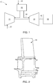
- Fig. 1 shows a schematic diagram of gas turbine engine 10 as may be used herein.
- the gas turbine engine 10 may include a compressor 15.
- the compressor 15 compresses an incoming flow of air 20.
- the compressor 15 delivers the compressed flow of air 20 to a combustor 25.
- the combustor 25 mixes the compressed flow of air 20 with a pressurized flow of fuel 30 and ignites the mixture to create a flow of hot combustion gases 35.
- the gas turbine engine 10 may include any number of combustors 25.
- the flow of hot combustion gases 35 is in turn delivered to a turbine 40.
- the flow of hot combustion gases 35 drives the turbine 40 so as to produce mechanical work.
- the mechanical work produced in the turbine 40 drives the compressor 15 via a shaft 45 and an external load 50 such as an electrical generator and the like.
- the gas turbine engine 10 may use natural gas, various types of syngas, liquid fuels, and/or other types of fuels and blends thereof.
- the gas turbine engine 10 may be any one of a number of different gas turbine engines offered by General Electric Company of Schenectady, New York, including, but not limited to, those such as a 7 or a 9 series heavy duty gas turbine engine and the like.
- the gas turbine engine 10 may have different configurations and may use other types of components. Other types of gas turbine engines also may be used herein. Multiple gas turbine engines, other types of turbines, and other types of power generation equipment also may be used herein together.
- Fig. 2 is a perspective view of an example of a hot gas path component 55 such as a bucket or nozzle.
- the hot gas path component 55 may receive a thermal barrier coating as will be described in more detail below.
- Other components such as shrouds, combustors, transition pieces, and the like may be used herein. Any component facing the hot combustion gases 35 may be used herein.
- Fig. 3 is a schematic diagram of a thermal barrier coating spallation detection system 100 as may be described herein.
- the thermal barrier coating spallation detection system 100 may include a stimulant radiation source 110.
- the stimulant radiation source 110 may be a conventional laser 120 and the like.
- the stimulant radiation source 110 may produce radiation in the form of light within a predetermined wavelength range.
- Other types of stimulant radiation sources 110 may include ultraviolet sources, infrared sources, and other types of conventional light sources.
- the thermal barrier coating spallation detection system 100 also may include one or more optic devices 130.
- the optic devices 130 may include conventional filters, resonators, sensors, and the like to emit the stimulant radiation and receive an emission radiation in response thereto.
- the thermal barrier coating spallation detection system 100 also may include one or more conventional optical filters 140 and a digital camera 150. A conventional photodetector also may be used.
- the optical filters 140 may focus and/or break down the colors of the received emission radiation such that the received emission radiation may be processed, displayed, and recorded by the digital camera. Different types of image processing software may be used herein. Other components and other configurations may be used herein.
- the thermal barrier coating spallation detection system 100 may be used with one or more hot gas path components 160.
- the hot gas path component 160 may be a bucket, a nozzle, a shroud, a combustor, a transition piece, and the like.
- the hot gas path component 160 may include a substrate 170.
- the substrate 170 may be made out of an alloy of nickel, cobalt, iron, or combinations thereof.
- the substrate 170 may include a high temperature, heat-resistant alloy, e.g., a superalloy.
- suitable high temperature nickel-based alloys include Inconel®, Nimonic®, Rene® ( e .
- the substrate 130 may be made out of one or more of nickel-base superalloys, cobalt-base superalloys, ceramic matrix composites, and similar materials.
- the hot gas path component 160 may include a base coat 180 on the substrate 160.
- the base coat 180 may be formed from a metallic oxidation-resistant material that protects the underlying substrate 170 and enables the thermal barrier coating described below to more tenaciously adhere to substrate.
- the base coat 180 thus provides functionality in the form of adhesion promotion and oxidation resistance.
- Suitable materials for the base coat 180 may include M 1 CrAlY alloy powders, where M 1 may represent a metal such as iron, nickel, platinum or cobalt.
- Other materials may include silicide compounds or elemental silicon, as well as metal aluminides such as nickel aluminide, platinum aluminide, or combinations thereof.
- the hot gas path component 160 may include a thermal barrier coating 190.
- the thermal barrier coating 190 may be a material capable of substantially reducing heat flow to the underlying substrate 170 of the hot gas path component 160, that is, forming a thermal barrier.
- the thermal barrier coating 190 may have a melting point greater than about 1000° C to about 3000° C.
- Ceramic thermal barrier coating materials include and are not limited to various zirconias, in particular chemically stabilized zirconias (for example, metal oxides blended with zirconia), such as yttria-stabilized zirconias, ceria-stabilized zirconias, calcia-stabilized zirconias, scandia-stabilized zirconias, magnesia-stabilized zirconias, india-stabilized zirconias, ytterbia-stabilized zirconias, lanthana-stabilized zirconias, gadolinia-stabilized zirconias, as well as mixtures of such stabilized zirconias.
- zirconias in particular chemically stabilized zirconias (for example, metal oxides blended with zirconia), such as yttria-stabilized zirconias, ceria-stabilized zirconias, calcia-stabilized zirconias, scandia-stabilized
- the hot gas path component 160 also may have a thermographic based phosphor layer 200 positioned between the base coat 180 and the thermal barrier coating 190.
- the thermographic based phosphor layer 200 may be made out of any type of luminescent material with a phosphorescent material and the like. Examples include materials such an yttrium aluminum garnet (YAG) crystal, lutetium aluminum garnet (LuAG) crystal, scandium aluminum garnet (ScAG) crystal, yttrium aluminum boron nitrogen garnet (YABNG) crystal, yttrium aluminum boron garnet (YABG) crystal, quartz crystal, sapphire crystal, or any other suitable crystal doped with a thermographic phosphor.
- YAG yttrium aluminum garnet
- LuAG scandium aluminum garnet
- ScAG yttrium aluminum boron nitrogen garnet
- YABG yttrium aluminum boron garnet
- the crystal may be doped with rare earth elements such as neodymium (Nd), chromium (Cr), erbium (Er), ytterbium (Yb), cerium (Ce), dysprosium (Dy), thulium (Tm), or any other suitable thermographic phosphor and combinations thereof.
- rare earth elements such as neodymium (Nd), chromium (Cr), erbium (Er), ytterbium (Yb), cerium (Ce), dysprosium (Dy), thulium (Tm), or any other suitable thermographic phosphor and combinations thereof.
- Other components and other configurations may be used herein.
- the base coat 180, the thermographic based phosphor layer 200, and the thermal barrier coating 190 may be applied in a conventional manner to the substrate 170 of the hot gas path component 160.
- the hot gas path component 160 may be put into operation within the gas turbine engine 10 in a conventional manner.
- the thermal barrier coating spallation detection system 100 may continuously or periodically monitor the thermal barrier coating 190.
- the thermal barrier coating spallation detection system 100 may direct stimulant radiation from the laser 120 or other type of stimulant radiation source 110 via the optical devices 130 and receive the emission radiation.
- the emission radiation may be processed and displayed via the optical filter 140 and the digital camera 150. As is shown in Fig.
- the thermal barrier coating 190 may be shown to be intact if the emission radiation results in a uniform response across a pixel grid 210 in the digital camera 150. As is shown in Fig. 5 , spallation may have occurred if there is a change shown in the pixel grid 210. In other words, the thermographic phosphor layer 200 may be visible due to spallation and caused to fluoresce so as to vary the nature of the emission radiation. The thermal barrier coating spallation detection system 100 thus may indicate that a shutdown is necessary for further inspection and possible repair.
- the thermal barrier coating spallation detection system 100 thus continuous or periodically monitors the hot gas path components 160 or other components protected by a thermal barrier coating. As a result, periodic inspections for spallation may be eliminated. Rather, the customer may operate the gas turbine engine 10 continuously until the thermal barrier coating spallation detection system 100 indicates that spallation has occurred. The overall costs of periodic outages for the periodic inspections thus may be avoided while the customer may confidently operate the gas turbine engine.
Landscapes
- Physics & Mathematics (AREA)
- Health & Medical Sciences (AREA)
- Life Sciences & Earth Sciences (AREA)
- Chemical & Material Sciences (AREA)
- Analytical Chemistry (AREA)
- Biochemistry (AREA)
- General Health & Medical Sciences (AREA)
- General Physics & Mathematics (AREA)
- Immunology (AREA)
- Pathology (AREA)
- Mathematical Physics (AREA)
- Turbine Rotor Nozzle Sealing (AREA)
- Radiation Pyrometers (AREA)
- Investigating, Analyzing Materials By Fluorescence Or Luminescence (AREA)
Abstract
Description
- The present application and the resultant patent relate generally to gas turbine engines and more particularly relate to a thermographic based thermal barrier coating spallation detection system that provides continuous, real time feedback on the integrity of the thermal barrier coatings on hot gas path components.
- Overall gas turbine operation and efficiency improves with higher operating temperatures. The lifetime of the components in the hot gas path, however, may be compromised given these higher temperatures and the hostile operating conditions. Ceramic coatings such as thermal barrier coatings may be used to protect the components from the hot temperatures, the chemical environment, and the physical conditions found within the hot gas path.
- Over time, the thermal barrier coatings may be subject to spallation. When spallation occurs, the hot gas path components must be removed and replaced within a short amount of time or catastrophic failure may occur. As a result, the gas turbine engine must be shut down on a periodic basis to inspect for spallation and other types of damage. Such a shutdown may be expensive in term of lost production and in terms of the man hours required for the inspection.
- The present application and the resultant patent thus provide a thermal barrier coating spallation detection system for a gas turbine. The thermal barrier coating spallation detection system may include a hot gas path component with a phosphor layer and a thermal barrier coating, a stimulant radiation source, and an optical device such that the optical device directs stimulant radiation at the thermal barrier coating and receives emission radiation. A change in the received emission radiation indicates spallation of the thermal barrier coating.
- The present application and the resultant patent further provide a method of inspecting a thermal barrier coating of a hot gas path component for spallation. The method may include the steps of emitting stimulant radiation at the thermal barrier coating, receiving emission radiation from the thermal barrier coating, comparing successive received emission radiation, and indicating spallation of the thermal barrier coating if a change is shown in the successive received emission radiation.
- The present application and the resultant patent further provide a thermal barrier coating spallation detection system for a gas turbine engine. The thermal barrier coating spallation detection system may include a hot gas path component with a phosphor layer and a thermal barrier coating, a stimulant radiation source, an optical device to direct stimulant radiation at the thermal barrier coating and receive emission radiation, and a digital camera in communication with the optical device. A change in the received emission radiation displayed on the digital camera indicates spallation of the thermal barrier coating.
- These and other features and improvements of the present application and the resultant patent will become apparent to one of ordinary skill in the art upon review of the following detailed description when taken in conjunction with the several drawings and the appended claims.
-
-
Fig. 1 is a schematic diagram of a gas turbine engine showing a compressor, a combustor, a turbine, and a load. -
Fig. 2 is a perspective view of a hot gas path component in the form of a turbine blade. -
Fig. 3 is a schematic diagram of a thermal barrier coating spallation detection system as may be described herein. -
Fig. 4 is a schematic diagram of an output of the thermal barrier coating spallation detection system ofFig. 3 showing no spallation. -
Fig. 5 is a schematic diagram of an output of the thermal barrier coating spallation detection system ofFig. 3 showing spallation. - Referring now to the drawings, in which like numerals refer to like elements throughout the several views,
Fig. 1 shows a schematic diagram ofgas turbine engine 10 as may be used herein. Thegas turbine engine 10 may include acompressor 15. Thecompressor 15 compresses an incoming flow ofair 20. Thecompressor 15 delivers the compressed flow ofair 20 to acombustor 25. Thecombustor 25 mixes the compressed flow ofair 20 with a pressurized flow offuel 30 and ignites the mixture to create a flow ofhot combustion gases 35. Although only asingle combustor 25 is shown, thegas turbine engine 10 may include any number ofcombustors 25. The flow ofhot combustion gases 35 is in turn delivered to aturbine 40. The flow ofhot combustion gases 35 drives theturbine 40 so as to produce mechanical work. The mechanical work produced in theturbine 40 drives thecompressor 15 via ashaft 45 and anexternal load 50 such as an electrical generator and the like. - The
gas turbine engine 10 may use natural gas, various types of syngas, liquid fuels, and/or other types of fuels and blends thereof. Thegas turbine engine 10 may be any one of a number of different gas turbine engines offered by General Electric Company of Schenectady, New York, including, but not limited to, those such as a 7 or a 9 series heavy duty gas turbine engine and the like. Thegas turbine engine 10 may have different configurations and may use other types of components. Other types of gas turbine engines also may be used herein. Multiple gas turbine engines, other types of turbines, and other types of power generation equipment also may be used herein together. -
Fig. 2 is a perspective view of an example of a hotgas path component 55 such as a bucket or nozzle. The hotgas path component 55 may receive a thermal barrier coating as will be described in more detail below. Other components such as shrouds, combustors, transition pieces, and the like may be used herein. Any component facing thehot combustion gases 35 may be used herein. -
Fig. 3 is a schematic diagram of a thermal barrier coatingspallation detection system 100 as may be described herein. The thermal barrier coatingspallation detection system 100 may include astimulant radiation source 110. In this example, thestimulant radiation source 110 may be aconventional laser 120 and the like. Thestimulant radiation source 110 may produce radiation in the form of light within a predetermined wavelength range. Other types ofstimulant radiation sources 110 may include ultraviolet sources, infrared sources, and other types of conventional light sources. - The thermal barrier coating
spallation detection system 100 also may include one or moreoptic devices 130. Theoptic devices 130 may include conventional filters, resonators, sensors, and the like to emit the stimulant radiation and receive an emission radiation in response thereto. The thermal barrier coatingspallation detection system 100 also may include one or more conventionaloptical filters 140 and adigital camera 150. A conventional photodetector also may be used. Theoptical filters 140 may focus and/or break down the colors of the received emission radiation such that the received emission radiation may be processed, displayed, and recorded by the digital camera. Different types of image processing software may be used herein. Other components and other configurations may be used herein. - The thermal barrier coating
spallation detection system 100 may be used with one or more hotgas path components 160. As described above, the hotgas path component 160 may be a bucket, a nozzle, a shroud, a combustor, a transition piece, and the like. The hotgas path component 160 may include asubstrate 170. Thesubstrate 170 may be made out of an alloy of nickel, cobalt, iron, or combinations thereof. For example, thesubstrate 170 may include a high temperature, heat-resistant alloy, e.g., a superalloy. Non-limiting examples of suitable high temperature nickel-based alloys include Inconel®, Nimonic®, Rene® (e.g., Rene® 80, Rene® 95 alloys), Udimet®, or combinations thereof. Specifically, thesubstrate 130 may be made out of one or more of nickel-base superalloys, cobalt-base superalloys, ceramic matrix composites, and similar materials. - The hot
gas path component 160 may include abase coat 180 on thesubstrate 160. Thebase coat 180 may be formed from a metallic oxidation-resistant material that protects theunderlying substrate 170 and enables the thermal barrier coating described below to more tenaciously adhere to substrate. Thebase coat 180 thus provides functionality in the form of adhesion promotion and oxidation resistance. Suitable materials for thebase coat 180 may include M1CrAlY alloy powders, where M1 may represent a metal such as iron, nickel, platinum or cobalt. Other materials may include silicide compounds or elemental silicon, as well as metal aluminides such as nickel aluminide, platinum aluminide, or combinations thereof. - The hot
gas path component 160 may include athermal barrier coating 190. Thethermal barrier coating 190 may be a material capable of substantially reducing heat flow to theunderlying substrate 170 of the hotgas path component 160, that is, forming a thermal barrier. Thethermal barrier coating 190 may have a melting point greater than about 1000° C to about 3000° C. Examples of ceramic thermal barrier coating materials include and are not limited to various zirconias, in particular chemically stabilized zirconias (for example, metal oxides blended with zirconia), such as yttria-stabilized zirconias, ceria-stabilized zirconias, calcia-stabilized zirconias, scandia-stabilized zirconias, magnesia-stabilized zirconias, india-stabilized zirconias, ytterbia-stabilized zirconias, lanthana-stabilized zirconias, gadolinia-stabilized zirconias, as well as mixtures of such stabilized zirconias. - The hot
gas path component 160 also may have a thermographic basedphosphor layer 200 positioned between thebase coat 180 and thethermal barrier coating 190. The thermographic basedphosphor layer 200 may be made out of any type of luminescent material with a phosphorescent material and the like. Examples include materials such an yttrium aluminum garnet (YAG) crystal, lutetium aluminum garnet (LuAG) crystal, scandium aluminum garnet (ScAG) crystal, yttrium aluminum boron nitrogen garnet (YABNG) crystal, yttrium aluminum boron garnet (YABG) crystal, quartz crystal, sapphire crystal, or any other suitable crystal doped with a thermographic phosphor. By way of example, the crystal may be doped with rare earth elements such as neodymium (Nd), chromium (Cr), erbium (Er), ytterbium (Yb), cerium (Ce), dysprosium (Dy), thulium (Tm), or any other suitable thermographic phosphor and combinations thereof. Other components and other configurations may be used herein. - In use, the
base coat 180, the thermographic basedphosphor layer 200, and thethermal barrier coating 190 may be applied in a conventional manner to thesubstrate 170 of the hotgas path component 160. The hotgas path component 160 may be put into operation within thegas turbine engine 10 in a conventional manner. The thermal barrier coatingspallation detection system 100 may continuously or periodically monitor thethermal barrier coating 190. Specifically, the thermal barrier coatingspallation detection system 100 may direct stimulant radiation from thelaser 120 or other type ofstimulant radiation source 110 via theoptical devices 130 and receive the emission radiation. The emission radiation may be processed and displayed via theoptical filter 140 and thedigital camera 150. As is shown inFig. 4 , thethermal barrier coating 190 may be shown to be intact if the emission radiation results in a uniform response across apixel grid 210 in thedigital camera 150. As is shown inFig. 5 , spallation may have occurred if there is a change shown in thepixel grid 210. In other words, thethermographic phosphor layer 200 may be visible due to spallation and caused to fluoresce so as to vary the nature of the emission radiation. The thermal barrier coatingspallation detection system 100 thus may indicate that a shutdown is necessary for further inspection and possible repair. - The thermal barrier coating
spallation detection system 100 thus continuous or periodically monitors the hotgas path components 160 or other components protected by a thermal barrier coating. As a result, periodic inspections for spallation may be eliminated. Rather, the customer may operate thegas turbine engine 10 continuously until the thermal barrier coatingspallation detection system 100 indicates that spallation has occurred. The overall costs of periodic outages for the periodic inspections thus may be avoided while the customer may confidently operate the gas turbine engine. - It should be apparent that the foregoing relates only to certain embodiments of the present application and the resultant patent. Numerous changes and modifications may be made herein by one of ordinary skill in the art without departing from the general spirit and scope of the invention as defined by the following claims and the equivalents thereof.
- Various aspects and embodiments of the present invention are defined by the following numbered clauses:
- 1. A thermal barrier coating spallation detection system for a gas turbine engine, comprising:
- a hot gas path component;
- the hot gas path component comprises a phosphor layer and a thermal barrier coating;
- a stimulant radiation source; and
- an optical device;
- wherein the optical device directs stimulant radiation at the thermal barrier coating and receives emission radiation; and
- wherein a change in the received emission radiation indicates spallation of the thermal barrier coating.
- 2. The thermal barrier coating spallation detection system of clause 1, wherein the stimulant radiation source comprises a laser.
- 3. The thermal barrier coating spallation detection system of any preceding clause, further comprising an optical filter in communication with the optical device.
- 4. The thermal barrier coating spallation detection system of any preceding clause, further comprising a digital camera in communication with the optical device.
- 5. The thermal barrier coating spallation detection system of any preceding clause, wherein the digital camera comprises a pixel grid.
- 6. The thermal barrier coating spallation detection system of any preceding clause, wherein a change in the pixel grid indicates spallation of the thermal barrier coating.
- 7. The thermal barrier coating spallation detection system of any preceding clause, wherein the phosphor layer comprises a thermographic based phosphor layer.
- 8. The thermal barrier coating spallation detection system of any preceding clause, wherein the thermographic based phosphor layer comprises a crystal.
- 9. The thermal barrier coating spallation detection system of any preceding clause, wherein the crystal comprises an yttrium aluminum garnet (YAG) crystal, a lutetium aluminum garnet (LuAG) crystal, a scandium aluminum garnet (ScAG) crystal, a yttrium aluminum boron nitrogen garnet (YABNG) crystal, an yttrium aluminum boron garnet (YABG) crystal, a quartz crystal, or a sapphire crystal.
- 10. The thermal barrier coating spallation detection system of any preceding clause, wherein the thermographic based phosphor layer comprises a rare earth element.
- 11. The thermal barrier coating spallation detection system of any preceding clause, wherein the rare earth element comprises neodymium (Nd), chromium (Cr), erbium (Er), ytterbium (Yb), cerium (Ce), dysprosium (Dy), or thulium (Tm).
- 12. The thermal barrier coating spallation detection system of any preceding clause, wherein the thermal barrier coating comprises a zirconia.
- 13. The thermal barrier coating spallation detection system of any preceding clause, wherein the hot gas path component comprises a substrate with a base coat thereon.
- 14. The thermal barrier coating spallation detection system of any preceding clause, wherein the phosphor layer is positioned between the thermal barrier coating and the base coat.
- 15. A method of inspecting a thermal barrier coating of a hot gas path component for spallation, comprising:
- emitting stimulant radiation at the thermal barrier coating;
- receiving emission radiation from the thermal barrier coating;
- comparing successive received emission radiation; and
- indicating spallation of the thermal barrier coating if a change is shown in the successive received emission radiation.
- 16. A thermal barrier coating spallation detection system for a gas turbine engine, comprising:
- a hot gas path component;
- the hot gas path component comprises a phosphor layer and a thermal barrier coating;
- a stimulant radiation source;
- an optical device;
- wherein the optical device directs stimulant radiation at the thermal barrier coating and receives emission radiation; and
- a digital camera in communication with the optical device;
- wherein a change in the received emission radiation displayed on the digital camera indicates spallation of the thermal barrier coating.
- 17. The thermal barrier coating spallation detection system of any preceding clause, wherein the stimulant radiation source comprises a laser.
- 18. The thermal barrier coating spallation detection system of any preceding clause, wherein the digital camera comprises a pixel grid and wherein a change in the pixel grid indicates spallation of the thermal barrier coating.
- 19. The thermal barrier coating spallation detection system of any preceding clause, wherein the phosphor layer comprises a thermographic based phosphor layer.
- 20. The thermal barrier coating spallation detection system of any preceding clause, wherein the hot gas path component comprises a base coat and wherein the phosphor layer is positioned between the thermal barrier coating and the base coat.
Claims (15)
- A thermal barrier coating spallation detection system for a gas turbine engine, comprising:a hot gas path component;the hot gas path component comprises a phosphor layer and a thermal barrier coating;a stimulant radiation source; andan optical device;wherein the optical device directs stimulant radiation at the thermal barrier coating and receives emission radiation; andwherein a change in the received emission radiation indicates spallation of the thermal barrier coating.
- The thermal barrier coating spallation detection system of claim 1, wherein the stimulant radiation source comprises a laser.
- The thermal barrier coating spallation detection system of claim 1 or 2, further comprising an optical filter in communication with the optical device.
- The thermal barrier coating spallation detection system of claim 1, 2 or 3, further comprising a digital camera in communication with the optical device.
- The thermal barrier coating spallation detection system of claim 4, wherein the digital camera comprises a pixel grid.
- The thermal barrier coating spallation detection system of claim 5, wherein a change in the pixel grid indicates spallation of the thermal barrier coating.
- The thermal barrier coating spallation detection system of any preceding claim, wherein the phosphor layer comprises a thermographic based phosphor layer.
- The thermal barrier coating spallation detection system of claim 7, wherein the thermographic based phosphor layer comprises a crystal.
- The thermal barrier coating spallation detection system of claim 8, wherein the crystal comprises an yttrium aluminum garnet (YAG) crystal, a lutetium aluminum garnet (LuAG) crystal, a scandium aluminum garnet (ScAG) crystal, a yttrium aluminum boron nitrogen garnet (YABNG) crystal, an yttrium aluminum boron garnet (YABG) crystal, a quartz crystal, or a sapphire crystal.
- The thermal barrier coating spallation detection system of claim 8, wherein the thermographic based phosphor layer comprises a rare earth element.
- The thermal barrier coating spallation detection system of claim 10, wherein the rare earth element comprises neodymium (Nd), chromium (Cr), erbium (Er), ytterbium (Yb), cerium (Ce), dysprosium (Dy), or thulium (Tm).
- The thermal barrier coating spallation detection system of any preceding claim, wherein the thermal barrier coating comprises a zirconia.
- The thermal barrier coating spallation detection system of any preceding claim, wherein the hot gas path component comprises a substrate with a base coat thereon.
- The thermal barrier coating spallation detection system of claim 13, wherein the phosphor layer is positioned between the thermal barrier coating and the base coat.
- A method of inspecting a thermal barrier coating of a hot gas path component for spallation, comprising:emitting stimulant radiation at the thermal barrier coating;receiving emission radiation from the thermal barrier coating;comparing successive received emission radiation; andindicating spallation of the thermal barrier coating if a change is shown in the successive received emission radiation.
Applications Claiming Priority (1)
| Application Number | Priority Date | Filing Date | Title |
|---|---|---|---|
| US15/726,759 US10641720B2 (en) | 2017-10-06 | 2017-10-06 | Thermal barrier coating spallation detection system |
Publications (1)
| Publication Number | Publication Date |
|---|---|
| EP3467481A1 true EP3467481A1 (en) | 2019-04-10 |
Family
ID=63833774
Family Applications (1)
| Application Number | Title | Priority Date | Filing Date |
|---|---|---|---|
| EP18196927.0A Withdrawn EP3467481A1 (en) | 2017-10-06 | 2018-09-26 | Thermal barrier coating spallation detection system |
Country Status (4)
| Country | Link |
|---|---|
| US (1) | US10641720B2 (en) |
| EP (1) | EP3467481A1 (en) |
| JP (1) | JP7258500B2 (en) |
| CN (1) | CN109632885A (en) |
Families Citing this family (5)
| Publication number | Priority date | Publication date | Assignee | Title |
|---|---|---|---|---|
| US11015252B2 (en) * | 2018-04-27 | 2021-05-25 | Applied Materials, Inc. | Protection of components from corrosion |
| EP4065943B1 (en) * | 2019-11-27 | 2024-11-20 | University of Central Florida Research Foundation, Inc. | Rare-earth doped thermal barrier coating bond coat for thermally grown oxide luminescence sensing, and including temperature monitoring and measuring a temperature gradient |
| US12365803B2 (en) | 2020-06-19 | 2025-07-22 | General Electric Company | Inspectable coatings and methods for using |
| US12319834B2 (en) | 2021-12-17 | 2025-06-03 | General Electric Company | Anti-corrosion material and application method |
| US12394804B2 (en) | 2022-08-16 | 2025-08-19 | General Electric Company | Thermal management of a fuel cell assembly |
Citations (5)
| Publication number | Priority date | Publication date | Assignee | Title |
|---|---|---|---|---|
| US6072568A (en) * | 1997-03-03 | 2000-06-06 | Howmet Research Corporation | Thermal barrier coating stress measurement |
| US20030115941A1 (en) * | 2001-12-20 | 2003-06-26 | General Electric Crd | Thermal barrier coatings, components, method and apparatus for determining past-service conditions and remaining life thereof |
| US20070134518A1 (en) * | 2003-08-18 | 2007-06-14 | Feist Joerg | Coatings and a method of optically detecting corrosion in coatings |
| US20090122832A1 (en) * | 2005-08-24 | 2009-05-14 | Jorg Peter Feist | Measurement, coating and monitoring system and method |
| FR2979015A1 (en) * | 2011-08-10 | 2013-02-15 | Snecma | METHOD FOR DETERMINING THE ADHESION OF A CERAMIC THERMAL BARRIER LAYER FORMED ON A SUBSTRATE BY APPLYING A THERMAL BARRIER SIDE LASER PULSE |
Family Cites Families (18)
| Publication number | Priority date | Publication date | Assignee | Title |
|---|---|---|---|---|
| US6804622B2 (en) | 2001-09-04 | 2004-10-12 | General Electric Company | Method and apparatus for non-destructive thermal inspection |
| US20050063450A1 (en) * | 2003-09-24 | 2005-03-24 | Siemens Aktiengesellschaft | Optical monitoring of thermal barrier coatings |
| JP2005146291A (en) * | 2003-11-11 | 2005-06-09 | Toshiba Corp | Thermal barrier coating member, evaluation method thereof, and high-temperature thermal apparatus |
| EP1930476A1 (en) * | 2006-12-07 | 2008-06-11 | Siemens Aktiengesellschaft | Layer system |
| US7549789B2 (en) | 2007-06-20 | 2009-06-23 | General Electric Company | Method and apparatus for thermographic nondestructive evaluation of an object |
| US8393784B2 (en) | 2008-03-31 | 2013-03-12 | General Electric Company | Characterization of flaws in composites identified by thermography |
| US8692887B2 (en) * | 2010-08-27 | 2014-04-08 | General Electric Company | Thermal imaging method and apparatus for evaluating coatings |
| US10169691B2 (en) * | 2013-01-17 | 2019-01-01 | Spectra Systems Corporation | Covert coating for authentication of materials |
| US9689262B2 (en) | 2013-06-05 | 2017-06-27 | General Electric Company | Thermographic inspection system for composite wind turbine blade |
| US9097657B2 (en) | 2013-07-23 | 2015-08-04 | General Electric Company | Leak detection of stator liquid cooling system |
| US9500611B2 (en) | 2013-09-26 | 2016-11-22 | General Electric Company | Lamp assembly for a thermographic nondestructive evaluation system |
| US10047613B2 (en) | 2015-08-31 | 2018-08-14 | General Electric Company | Gas turbine components having non-uniformly applied coating and methods of assembling the same |
| US20170081753A1 (en) | 2015-09-21 | 2017-03-23 | General Electric Company | Thermal barrier coating system and processes for forming a thermal barrier coating system |
| US20170122561A1 (en) | 2015-10-28 | 2017-05-04 | General Electric Company | Methods of repairing a thermal barrier coating of a gas turbine component and the resulting components |
| US10221703B2 (en) | 2015-11-24 | 2019-03-05 | General Electric Company | Articles having damage-tolerant thermal barrier coating |
| US10201831B2 (en) | 2015-12-09 | 2019-02-12 | General Electric Company | Coating inspection method |
| US20170241308A1 (en) | 2016-02-24 | 2017-08-24 | Ford Global Technologies, Llc | Oil maintenance strategy for electrified vehicles |
| CN106066319A (en) * | 2016-07-19 | 2016-11-02 | 中国科学院上海硅酸盐研究所 | The lossless detection method of thermally grown oxide layer residual stress in thermal barrier coating |
-
2017
- 2017-10-06 US US15/726,759 patent/US10641720B2/en active Active
-
2018
- 2018-09-26 EP EP18196927.0A patent/EP3467481A1/en not_active Withdrawn
- 2018-10-01 JP JP2018186330A patent/JP7258500B2/en active Active
- 2018-10-08 CN CN201811167512.1A patent/CN109632885A/en active Pending
Patent Citations (5)
| Publication number | Priority date | Publication date | Assignee | Title |
|---|---|---|---|---|
| US6072568A (en) * | 1997-03-03 | 2000-06-06 | Howmet Research Corporation | Thermal barrier coating stress measurement |
| US20030115941A1 (en) * | 2001-12-20 | 2003-06-26 | General Electric Crd | Thermal barrier coatings, components, method and apparatus for determining past-service conditions and remaining life thereof |
| US20070134518A1 (en) * | 2003-08-18 | 2007-06-14 | Feist Joerg | Coatings and a method of optically detecting corrosion in coatings |
| US20090122832A1 (en) * | 2005-08-24 | 2009-05-14 | Jorg Peter Feist | Measurement, coating and monitoring system and method |
| FR2979015A1 (en) * | 2011-08-10 | 2013-02-15 | Snecma | METHOD FOR DETERMINING THE ADHESION OF A CERAMIC THERMAL BARRIER LAYER FORMED ON A SUBSTRATE BY APPLYING A THERMAL BARRIER SIDE LASER PULSE |
Non-Patent Citations (2)
| Title |
|---|
| GENTLEMAN M M ET AL: "Concepts for luminescence sensing of thermal barrier coatings", SURFACE AND COATINGS TECHNOLOGY, ELSEVIER BV, AMSTERDAM, NL, vol. 188-189, 1 November 2004 (2004-11-01), pages 93 - 100, XP004622192, ISSN: 0257-8972, DOI: 10.1016/J.SURFCOAT.2004.08.005 * |
| PILGRIM C C ET AL: "Photoluminescence for quantitative non-destructive evaluation of thermal barrier coating erosion", SURFACE AND COATINGS TECHNOLOGY, vol. 209, 19 August 2012 (2012-08-19), pages 44 - 51, XP028942875, ISSN: 0257-8972, DOI: 10.1016/J.SURFCOAT.2012.08.025 * |
Also Published As
| Publication number | Publication date |
|---|---|
| US10641720B2 (en) | 2020-05-05 |
| JP2019108888A (en) | 2019-07-04 |
| JP7258500B2 (en) | 2023-04-17 |
| CN109632885A (en) | 2019-04-16 |
| US20190107499A1 (en) | 2019-04-11 |
Similar Documents
| Publication | Publication Date | Title |
|---|---|---|
| EP3467481A1 (en) | Thermal barrier coating spallation detection system | |
| CN102601571A (en) | Damage-repairing method of transition piece and transition piece | |
| US20170009584A1 (en) | Systems and Methods for Turbine Blade Repair | |
| US20180292090A1 (en) | Hybrid component comprising a metal-reinforced ceramic matrix composite material | |
| US20190368051A1 (en) | Thermal barrier coating system compatible with overlay | |
| US8017250B2 (en) | Method for production of a coating system | |
| US10760422B2 (en) | Pre-sintered preform for repair of service run gas turbine components | |
| CN101578395A (en) | Layer system | |
| CN102356182A (en) | Two-layer porous layer system having a pyrochlore phase | |
| CN101302104A (en) | Ceramic powders, ceramic layers and layer systems containing pyrochlore phases and oxides | |
| CN109642467A (en) | Turbine system with seal member | |
| RU2392349C2 (en) | Coating for part out of heat-resistant alloy based on iron or nickel or cobalt | |
| US20090123722A1 (en) | Coating system | |
| JP5638548B2 (en) | Thermal barrier coating and gas turbine component and gas turbine using the same | |
| JP5091642B2 (en) | Thermal barrier coating and gas turbine component and gas turbine using the same | |
| US8252601B2 (en) | Method for designating a component having a heat insulation layer and for determining its operating time | |
| EP3957827A1 (en) | A coating system for a component of a gas turbine engine | |
| EP4286340B1 (en) | Low thermal conductivity, high toughness tbc compositions | |
| Schimmoller | Technology pushes gas turbines higher | |
| US8123464B2 (en) | Coating optimization process using a coupon and component comprising a coupon | |
| Viswanathan et al. | Hybrid Thermally Efficient Core (HyTEC) HyTEC Phase 1–HTEBC Final Report | |
| KR102115412B1 (en) | Composition for combustion fuel of heat engine and method of heat engine combustion coating using the same | |
| CN110475944B (en) | Gas turbine component and method of assembling same | |
| Kang et al. | New Repair Technologies for 7FA/FA+ Class Stage 1 Buckets | |
| Singhal et al. | Ceramic turbine components research and development. Part 2. evaluation of MCrAlY/ZrO/sub 2/(Y/sub 2/O/sub 3/) thermal-barrier coatings exposed to simulated gas turbine environments. Final report |
Legal Events
| Date | Code | Title | Description |
|---|---|---|---|
| PUAI | Public reference made under article 153(3) epc to a published international application that has entered the european phase |
Free format text: ORIGINAL CODE: 0009012 |
|
| AK | Designated contracting states |
Kind code of ref document: A1 Designated state(s): AL AT BE BG CH CY CZ DE DK EE ES FI FR GB GR HR HU IE IS IT LI LT LU LV MC MK MT NL NO PL PT RO RS SE SI SK SM TR |
|
| AX | Request for extension of the european patent |
Extension state: BA ME |
|
| 17P | Request for examination filed |
Effective date: 20191010 |
|
| RBV | Designated contracting states (corrected) |
Designated state(s): AL AT BE BG CH CY CZ DE DK EE ES FI FR GB GR HR HU IE IS IT LI LT LU LV MC MK MT NL NO PL PT RO RS SE SI SK SM TR |
|
| 17Q | First examination report despatched |
Effective date: 20200113 |
|
| STAA | Information on the status of an ep patent application or granted ep patent |
Free format text: STATUS: THE APPLICATION IS DEEMED TO BE WITHDRAWN |
|
| 18D | Application deemed to be withdrawn |
Effective date: 20200724 |