EP3467412A1 - Cross opening door mechanism and refrigerator - Google Patents
Cross opening door mechanism and refrigerator Download PDFInfo
- Publication number
- EP3467412A1 EP3467412A1 EP16903881.7A EP16903881A EP3467412A1 EP 3467412 A1 EP3467412 A1 EP 3467412A1 EP 16903881 A EP16903881 A EP 16903881A EP 3467412 A1 EP3467412 A1 EP 3467412A1
- Authority
- EP
- European Patent Office
- Prior art keywords
- gear
- hinge
- transmission
- bottom plate
- gears
- Prior art date
- Legal status (The legal status is an assumption and is not a legal conclusion. Google has not performed a legal analysis and makes no representation as to the accuracy of the status listed.)
- Granted
Links
Images





Classifications
-
- E—FIXED CONSTRUCTIONS
- E05—LOCKS; KEYS; WINDOW OR DOOR FITTINGS; SAFES
- E05D—HINGES OR SUSPENSION DEVICES FOR DOORS, WINDOWS OR WINGS
- E05D15/00—Suspension arrangements for wings
- E05D15/48—Suspension arrangements for wings allowing alternative movements
- E05D15/50—Suspension arrangements for wings allowing alternative movements for opening at either of two opposite edges
-
- E—FIXED CONSTRUCTIONS
- E05—LOCKS; KEYS; WINDOW OR DOOR FITTINGS; SAFES
- E05D—HINGES OR SUSPENSION DEVICES FOR DOORS, WINDOWS OR WINGS
- E05D15/00—Suspension arrangements for wings
- E05D15/48—Suspension arrangements for wings allowing alternative movements
- E05D15/50—Suspension arrangements for wings allowing alternative movements for opening at either of two opposite edges
- E05D15/505—Suspension arrangements for wings allowing alternative movements for opening at either of two opposite edges by radial separation of the hinge parts at the hinge axis
-
- E—FIXED CONSTRUCTIONS
- E05—LOCKS; KEYS; WINDOW OR DOOR FITTINGS; SAFES
- E05D—HINGES OR SUSPENSION DEVICES FOR DOORS, WINDOWS OR WINGS
- E05D7/00—Hinges or pivots of special construction
- E05D7/02—Hinges or pivots of special construction for use on the right-hand as well as the left-hand side; Convertible right-hand or left-hand hinges
-
- E—FIXED CONSTRUCTIONS
- E05—LOCKS; KEYS; WINDOW OR DOOR FITTINGS; SAFES
- E05D—HINGES OR SUSPENSION DEVICES FOR DOORS, WINDOWS OR WINGS
- E05D7/00—Hinges or pivots of special construction
- E05D7/10—Hinges or pivots of special construction to allow easy separation or connection of the parts at the hinge axis
- E05D7/1061—Hinges or pivots of special construction to allow easy separation or connection of the parts at the hinge axis in a radial direction
-
- F—MECHANICAL ENGINEERING; LIGHTING; HEATING; WEAPONS; BLASTING
- F25—REFRIGERATION OR COOLING; COMBINED HEATING AND REFRIGERATION SYSTEMS; HEAT PUMP SYSTEMS; MANUFACTURE OR STORAGE OF ICE; LIQUEFACTION SOLIDIFICATION OF GASES
- F25D—REFRIGERATORS; COLD ROOMS; ICE-BOXES; COOLING OR FREEZING APPARATUS NOT OTHERWISE PROVIDED FOR
- F25D23/00—General constructional features
- F25D23/02—Doors; Covers
-
- F—MECHANICAL ENGINEERING; LIGHTING; HEATING; WEAPONS; BLASTING
- F25—REFRIGERATION OR COOLING; COMBINED HEATING AND REFRIGERATION SYSTEMS; HEAT PUMP SYSTEMS; MANUFACTURE OR STORAGE OF ICE; LIQUEFACTION SOLIDIFICATION OF GASES
- F25D—REFRIGERATORS; COLD ROOMS; ICE-BOXES; COOLING OR FREEZING APPARATUS NOT OTHERWISE PROVIDED FOR
- F25D23/00—General constructional features
- F25D23/02—Doors; Covers
- F25D23/028—Details
-
- E—FIXED CONSTRUCTIONS
- E05—LOCKS; KEYS; WINDOW OR DOOR FITTINGS; SAFES
- E05Y—INDEXING SCHEME ASSOCIATED WITH SUBCLASSES E05D AND E05F, RELATING TO CONSTRUCTION ELEMENTS, ELECTRIC CONTROL, POWER SUPPLY, POWER SIGNAL OR TRANSMISSION, USER INTERFACES, MOUNTING OR COUPLING, DETAILS, ACCESSORIES, AUXILIARY OPERATIONS NOT OTHERWISE PROVIDED FOR, APPLICATION THEREOF
- E05Y2900/00—Application of doors, windows, wings or fittings thereof
- E05Y2900/30—Application of doors, windows, wings or fittings thereof for domestic appliances
- E05Y2900/31—Application of doors, windows, wings or fittings thereof for domestic appliances for refrigerators
-
- F—MECHANICAL ENGINEERING; LIGHTING; HEATING; WEAPONS; BLASTING
- F25—REFRIGERATION OR COOLING; COMBINED HEATING AND REFRIGERATION SYSTEMS; HEAT PUMP SYSTEMS; MANUFACTURE OR STORAGE OF ICE; LIQUEFACTION SOLIDIFICATION OF GASES
- F25D—REFRIGERATORS; COLD ROOMS; ICE-BOXES; COOLING OR FREEZING APPARATUS NOT OTHERWISE PROVIDED FOR
- F25D2323/00—General constructional features not provided for in other groups of this subclass
- F25D2323/02—Details of doors or covers not otherwise covered
- F25D2323/022—Doors that can be pivoted either left-handed or right-handed
-
- F—MECHANICAL ENGINEERING; LIGHTING; HEATING; WEAPONS; BLASTING
- F25—REFRIGERATION OR COOLING; COMBINED HEATING AND REFRIGERATION SYSTEMS; HEAT PUMP SYSTEMS; MANUFACTURE OR STORAGE OF ICE; LIQUEFACTION SOLIDIFICATION OF GASES
- F25D—REFRIGERATORS; COLD ROOMS; ICE-BOXES; COOLING OR FREEZING APPARATUS NOT OTHERWISE PROVIDED FOR
- F25D2323/00—General constructional features not provided for in other groups of this subclass
- F25D2323/02—Details of doors or covers not otherwise covered
- F25D2323/024—Door hinges
Definitions
- the present invention relates to the technical field of household appliances, and in particular, to a left-right door opening mechanism and a refrigerator.
- a door is generally opened from the left side, and also has the function of opening from the right side, but it is necessary for an after-sales engineer to visit to replace a hinge or change the position of the hinge.
- This method has higher skill requirements for after-sales maintenance personnel and also reduces the use experience of a user.
- the technical problem to be solved by the present invention is to provide a left-right door opening mechanism and a refrigerator, which are capable of opening a door of the refrigerator from the left side or the right side.
- a left-right door opening mechanism comprises a hinge module arranged on a refrigerator door body and a transmission module arranged on a refrigerator cabinet body, wherein the transmission module comprises a transmission bottom plate, two first gears oppositely arranged on the transmission bottom plate, a transmission rack which is in transmission through the first gears, and second gears which are in transmission with the first gears respectively; the transmission rack is guided and limited by the second gears; the hinge module comprises a hinge bottom plate and two hinges oppositely arranged on the hinge bottom plate; the hinges are in transmission with the first gears; when the two hinges are respectively meshed with the first gears, the door body is locked; when the hinge on one side is disengaged from the first gear but the hinge on the other side is still meshed with the other first gear, the door body is opened.
- the transmission module comprises a transmission bottom plate, two first gears oppositely arranged on the transmission bottom plate, a transmission rack which is in transmission through the first gears, and second gears which are in transmission with the first gears respectively; the transmission rack is
- the hinge and the second gear are located on two sides of each of the first gears, and the second gear is located inside each of the two first gears; the hinge is located outside each of the first gears.
- the first gear is rotatably mounted on the transmission bottom plate by means of a first rotating shaft; the first gear comprises a first tooth portion meshed with the corresponding hinge, and a second tooth portion meshed with the corresponding second gear and the corresponding transmission rack.
- the second gear is rotatably mounted on the transmission bottom plate by means of a second rotating shaft; the second gear comprises a third tooth portion meshed with the first gear; the second rotating shaft is located at a non-center position of the second gear.
- a limiting member is arranged on the transmission rack; a sliding groove for accommodating the limiting member is arranged at the upper part of the second gear.
- a fourth tooth portion which is meshed with the first gear is arranged on each of the two ends of the transmission rack; a fixing portion is further arranged outside the fourth tooth portion; the first gear is provided with an accommodating groove for accommodating the fixing portion.
- the hinge is rotatably mounted on the hinge bottom plate by means of a third rotating shaft; the hinge comprises a fifth tooth portion which is meshed with the corresponding first gear.
- the hinge comprises a hinge body and an extension portion which extends outwards from the hinge body; the hinge body is rotatably mounted on the hinge bottom plate; the fifth tooth portion is arranged at the end part of the extension portion; the transmission bottom plate is fixedly provided with a slot for limiting the extension portion.
- a guiding slider is arranged on the transmission bottom plate; the guiding slider is provided with a guiding groove used for guiding the transmission rack along a transmission direction.
- the present invention further discloses a refrigerator which comprises the above-mentioned left-right door opening mechanism.
- the present invention has the following beneficial effects.
- the rotating shaft is arranged on the door body, and the door can be opened from the left side or the right side, without making any adjustment.
- the door opening and closing process is smooth and free of blocking and impact noise.
- the door body is unlikely to fall off during the opening and closing process, and provides an excellent use experience for a user.
- the terms of the spatial relative positions may be intended to include different orientations of the device in use or operation other than the orientations shown in the accompanying drawings.
- the units that are described as being located on the “right side” of other units or features will be located on the “left side” of other units or features if the device in the accompanying drawings is turned upside down.
- the exemplary term “right side” can encompass both the orientations of left side and right side.
- the device may be otherwise oriented (rotated by 90 degrees or facing other directions) and the space-related descriptors used here are interpreted accordingly.
- a left-right door opening mechanism in a specific embodiment of the present invention comprises a hinge module 100 arranged on a refrigerator door body and a transmission module 200 arranged on a refrigerator cabinet body.
- the hinge module 100 and the transmission module 200 are mounted by means of components such as hinges and gears provided on two ends.
- the hinge module 100 and the transmission module 200 each have at least one end that is rotatably fixed, such that the door of the refrigerator may be opened from the left side or the right side.
- the transmission module 200 in the present embodiment comprises a transmission bottom plate 21, two first gears 22 oppositely arranged on the transmission bottom plate, a transmission rack 23 which is in transmission through the first gears, and second gears 24 which are in transmission with the first gears respectively.
- the transmission rack 23 is guided and limited by the second gears 24.
- the hinge module 100 comprises a hinge bottom plate 11 and two hinges 12 oppositely arranged on the hinge bottom plate.
- the hinges 12 are in transmission with the first gears 22.
- the door body is locked.
- the hinge 12 on one side is disengaged from the first gear 22 but the hinge on the other side is still meshed with the other first gear, the door body is opened.
- the left-right door opening mechanism in the present embodiment will be described in detail below in conjunction with specific components in the hinge module and the transmission module.
- the transmission module 200 in the present embodiment comprises an elongated transmission bottom plate 21.
- a first rotating shaft 211 and a second rotating shaft 212 are respectively arranged on the left and right sides of the transmission bottom plate 21.
- the first rotating shaft 211 is located outside the second rotating shaft 212.
- the first gear 22 and the second gear 24 are rotatably mounted on the transmission bottom plate 21 by means of the first rotating shaft 211 and the second rotating shaft 212, respectively.
- the first gear 22 and the second gear 24 are meshed with each other.
- the first gear 22 is circular and is rotatably mounted on the transmission bottom plate 21 by means of the first rotating shaft 211.
- the first rotating shaft 211 is mounted at a center position of the first gear 22.
- the first gear 22 comprises a first tooth portion 221 meshed with the corresponding hinge and a second tooth portion 222 meshed with the corresponding second gear and the corresponding transmission rack.
- first tooth portion 221 and the second tooth portion 222 which are separated from each other are arranged outside the first gear 22 in the present embodiment.
- first tooth portion 221 and the second tooth portion 222 may also be arranged as a whole, and the purpose of transmission with the hinge, the second gear and the transmission rack may also be achieved.
- the second gear 24 is arranged in a fan shape, and is rotatably mounted on the transmission bottom plate 21 by means of the second rotating shaft 212.
- the second rotating shaft 212 is mounted at a non-center position of the second gear 24.
- the second gear 24 comprises a third tooth portion 241 meshed with the first gear.
- the third tooth portion 241 is arranged on the fan-shaped surface of the second gear 24.
- a sliding groove 242 which is in an approximately arc shape is also arranged on the top of the second gear 24.
- the second gear 24 is higher than the first gear 22, but the bottom surface of the sliding groove 242 is arranged at the same height as the top surface of the first gear 22.
- the sliding groove 242 is configured to have an opening, so that the assembly of the transmission rack 23 and the second gear 24 can be performed quickly.
- the sliding groove may also be configured to have no opening, and the heights of the first gear 22 and the second gear 24 may also be equal or the first gear 22 is higher than the second gear 24, which will not be described here in detail.
- the transmission rack 23 is longitudinal.
- a fourth tooth portion 231 which is meshed with the corresponding first gear is arranged on each of the two ends of the transmission rack 23.
- the fourth tooth portion 231 and the second tooth portion 222 on the first gear 22 are meshed with each other.
- the transmission rack is provided with a limiting member 232 which is perpendicular to the top surface of the second gear 24.
- the transmission rack 23 is higher than the first gear 22 and the second gear 24, such that the limiting member 232 of the transmission rack 23 may be vertically assembled into the sliding groove 242 on the second gear 24.
- the first gear 22 is further provided with an accommodating groove 223 on the side of the second tooth portion 222.
- the transmission rack 23 is provided with a fixing portion 233 outside the fourth tooth portion 231.
- the fixing portion 233 has a shape corresponding to the shape of the accommodating groove 223. After the transmission rack 23 is meshed with the first gear 22 by means of the second tooth portion 222 and the fourth tooth portion 231, the fixing portion 233 is fixedly accommodated inside the accommodating groove 223, thereby fixing the end part of the transmission rack.
- Fig. 6 illustrates an assembly schematic diagram of the transmission module.
- the assembly and transmission principle of the transmission module is specifically as follows.
- the first gear 22 and the second gear 24 are rotatably mounted at the end part of the transmission bottom plate 21 respectively by means of the first rotating shaft 211 and the second rotating shaft 212.
- a pair of first gear 22 and second gear 24 is arranged on each of the two sides of the transmission bottom plate 21.
- the first gear 22 and the second gear 24 are meshed with each other by means of the second tooth portion 222 and the second tooth portion 241.
- the first gear 22 can drive the second gear 24 to rotate along the second rotating shaft 212 while rotating along the first rotating shaft 211.
- the transmission rack 23 and the two first gears 22 are meshed with each other by means of the second tooth portion 222 and the fourth tooth portion 231, respectively.
- the first gear 22 on one side which is in rotation, can drive the transmission rack 23 to move horizontally, so that the transmission rack can drive the first gear 22 on the other side to rotate in the same direction.
- the fixing portion 233 at the end part of the transmission rack 23 and the accommodating groove 223 on the first gear 22 are used to limit the transmission rack 23 and the first gear 22.
- the limiting member 232 on the transmission rack 23 is always located in the sliding groove 242 on the second gear 24 to ensure that the transmission rack 23 is not disengaged from the transmission position. Because the second gear rotates around the second rotating shaft, and meanwhile the transmission rack is linearly driven, the shape of the sliding groove 242 is substantially in an arc shape. In addition, the sliding groove 242 is arranged between the second rotating shaft and the third tooth portion, thereby providing a sliding track for the limiting member 232 on the transmission rack 23.
- a guiding slider 213 is further arranged on the transmission bottom plate 21 and located between the two second gears.
- the guiding slider 213 is provided with a guiding groove 214 for guiding the transmission rack in the transmission direction.
- the guiding slider 213 is fixed on the transmission bottom plate 21 by means of a plurality of nuts.
- the mounting manners, such as buckling may be adopted, or the transmission bottom plate and the guiding slider may be integrally formed, which will not be described here.
- the hinge module 100 in the present embodiment comprises an elongated hinge bottom plate 11.
- Third rotating shafts 111 which are symmetrically distributed are arranged on two ends of the hinge bottom plate 11 respectively.
- a hinge which is used for connecting the hinge bottom plate and the transmission module is rotatably mounted on each of the third rotating shafts 111.
- the hinge 12 comprises a hinge body 121 and an extension portion 122 which extends outwards from the hinge body 121.
- the hinge body 121 is rotatably mounted on the hinge bottom plate 11.
- a fifth tooth portion 123 is arranged on the side of the end part of the extension portion 122. The fifth tooth portion 123 on the hinge 12 and the first tooth portion 221 of the first gear 22 on the transmission bottom plate 21 are meshed with each other.
- the hinge module on one side When the user opens the door from one side, the hinge module on one side is pulled.
- the hinge 12 on this side moves outwards by means of the fifth tooth portion 123.
- the fifth tooth portion 123 and the first tooth portion 221 are meshed with each other to drive the first gear 22 on the transmission module to rotate around the first rotating shaft 211.
- the fifth tooth portion 123 and the first tooth portion 221 are separated from each other. That is, the hinge 12 and the first gear 22 are separated from each other, the first gear 22 stops rotating, and the hinge and the hinge body on the other side are rotatably arranged to achieve the purpose of opening the door from one side.
- a slot 215 is fixedly arranged on each of the two ends of the transmission bottom plate 21 and used for limiting the extension portion.
- the slots 215 are formed in a manner of buckling.
- the hinge 12 moves in a direction (perpendicular to a movement direction of the transmission rack) of the slot 215 while moving relative to the first gear 22.
- the left-right door opening mechanism is in a locked state.
- the hinge module is clamped with the transmission module.
- the hinge 12 is rotatably mounted on the hinge bottom plate 11.
- the first gear 22, the second gear 24 and the transmission rack 23 are mounted on the transmission bottom plate 21.
- the hinge 12 on the left side is meshed with the first tooth portion 221 on the first gear 22 by means of the fifth tooth portion 123 at the front end.
- the second tooth portion 222 of the first gear 22 is meshed with the third tooth portion 221 of the second gear 24.
- the fourth tooth portion 231 at the left end of the transmission rack 23 is not meshed with the first tooth portion 221 of the first gear 22.
- the fixing portion 233 at the left end of the transmission rack 23 is located in the accommodating groove 223 of the first gear 22.
- the limiting member 232 of the transmission rack 23 is vertically assembled in the sliding groove 242 on the second gear 24.
- the assembly relationship on the right side of the left-right door opening mechanism is symmetric with that on the left side, and will not be described here again.
- the hinge bottom plate 11 on the left side is pulled to drive the hinge 12 on the left side to move outwards.
- the hinge 12 on the left side is meshed with the first tooth portion 221 by means of the fifth tooth portion 123 to drive the first gear 22 to move anticlockwise.
- the second tooth portion 222 on the first gear 22 and the fourth tooth portion 231 on the transmission rack 23 are meshed to further drive the transmission rack 23 to move leftwards.
- the second tooth portion 222 of the first gear 22 and the third tooth portion 241 of the second gear 24 are meshed with each other.
- the first gear 22 may drive the second gear 24 to rotate clockwise.
- the limiting member 232 on the transmission rack 23 moves leftwards along the sliding groove 242.
- the fourth tooth portion 231 on the right side of the transmission rack 23 drives the first gear 22 on the right side to rotate clockwise.
- the first gear 22 simultaneously drives the second gear 24 on the right side to rotate clockwise, and the hinge 12 on the right side moves inwards.
- the hinge 12 on the left side gradually moves outwards till the hinge 12 is disengaged from the first gear 22 on the left side.
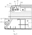
- the left-right door opening mechanism on the left side is in an opened state, and the structure thereof is shown in Fig. 10 .
- the hinge 12 on the right side in this case gradually moves inwardly, and is further locked with the first gear 22 on the right side.
- the third rotating shaft on the hinge bottom plate on the right side serves as a central shaft for the refrigerator door body to rotate.
- the hinge on the right side moves outwards.
- the hinge on the left side in this case will move inwards reversely till being gradually locked.
- the third rotating shaft on the hinge bottom plate on the left side serves as a central shaft for the refrigerator door body to rotate.
- the hinge on the right side moves inwards, and the transmission rack gradually moves leftwards till being restored to the locked state.
- the transmission relationship of the left-right door opening mechanism when the door is opened or locked from the right side is similar to that of opening or locking the door from the left side, and will not be described here.
- the left-right door opening mechanism in the present embodiment is described by taking a refrigerator as an example.
- the left-right door opening mechanism may be applied to any device comprising a door body and a refrigerator body, such as a wine cabinet, etc., and will not be described in detail here.
- the present invention has the following beneficial effects.
- the rotating shaft is arranged on the door body, and the door can be opened from the left side or the right side, without making any adjustment.
- the door opening and closing process is smooth and free of blocking and impact noise.
- the door body is unlikely to fall off during the opening and closing process, and provides an excellent use experience for a user.
Landscapes
- Engineering & Computer Science (AREA)
- Mechanical Engineering (AREA)
- Chemical & Material Sciences (AREA)
- Combustion & Propulsion (AREA)
- Physics & Mathematics (AREA)
- Thermal Sciences (AREA)
- General Engineering & Computer Science (AREA)
- Refrigerator Housings (AREA)
- Transmission Devices (AREA)
Abstract
Description
- This application claims the priority of Chinese Patent Application No.
201610377865.9 filed on May 31, 2016 - The present invention relates to the technical field of household appliances, and in particular, to a left-right door opening mechanism and a refrigerator.
- At present, for a commercially available refrigerator, a door is generally opened from the left side, and also has the function of opening from the right side, but it is necessary for an after-sales engineer to visit to replace a hinge or change the position of the hinge. This method has higher skill requirements for after-sales maintenance personnel and also reduces the use experience of a user.
- In view of the above problems, it is necessary to provide a left-right door opening mechanism and a refrigerator.
- In view of the defects of the prior art, the technical problem to be solved by the present invention is to provide a left-right door opening mechanism and a refrigerator, which are capable of opening a door of the refrigerator from the left side or the right side.
- In order to solve the above technical problem, the technical solution of the present invention is implemented as follows.
- A left-right door opening mechanism comprises a hinge module arranged on a refrigerator door body and a transmission module arranged on a refrigerator cabinet body, wherein the transmission module comprises a transmission bottom plate, two first gears oppositely arranged on the transmission bottom plate, a transmission rack which is in transmission through the first gears, and second gears which are in transmission with the first gears respectively; the transmission rack is guided and limited by the second gears; the hinge module comprises a hinge bottom plate and two hinges oppositely arranged on the hinge bottom plate; the hinges are in transmission with the first gears; when the two hinges are respectively meshed with the first gears, the door body is locked; when the hinge on one side is disengaged from the first gear but the hinge on the other side is still meshed with the other first gear, the door body is opened.
- As an improvement of the present invention, the hinge and the second gear are located on two sides of each of the first gears, and the second gear is located inside each of the two first gears; the hinge is located outside each of the first gears.
- As a further improvement of the present invention, the first gear is rotatably mounted on the transmission bottom plate by means of a first rotating shaft; the first gear comprises a first tooth portion meshed with the corresponding hinge, and a second tooth portion meshed with the corresponding second gear and the corresponding transmission rack.
- As a further improvement of the present invention, the second gear is rotatably mounted on the transmission bottom plate by means of a second rotating shaft; the second gear comprises a third tooth portion meshed with the first gear; the second rotating shaft is located at a non-center position of the second gear.
- As a further improvement of the present invention, a limiting member is arranged on the transmission rack; a sliding groove for accommodating the limiting member is arranged at the upper part of the second gear.
- As a further improvement of the present invention, a fourth tooth portion which is meshed with the first gear is arranged on each of the two ends of the transmission rack; a fixing portion is further arranged outside the fourth tooth portion; the first gear is provided with an accommodating groove for accommodating the fixing portion.
- As a further improvement of the present invention, the hinge is rotatably mounted on the hinge bottom plate by means of a third rotating shaft; the hinge comprises a fifth tooth portion which is meshed with the corresponding first gear.
- As a further improvement of the present invention, the hinge comprises a hinge body and an extension portion which extends outwards from the hinge body; the hinge body is rotatably mounted on the hinge bottom plate; the fifth tooth portion is arranged at the end part of the extension portion; the transmission bottom plate is fixedly provided with a slot for limiting the extension portion.
- As a further improvement of the present invention, a guiding slider is arranged on the transmission bottom plate; the guiding slider is provided with a guiding groove used for guiding the transmission rack along a transmission direction.
- Correspondingly, the present invention further discloses a refrigerator which comprises the above-mentioned left-right door opening mechanism.
- The present invention has the following beneficial effects.
- The rotating shaft is arranged on the door body, and the door can be opened from the left side or the right side, without making any adjustment.
- It is ensured that the door opening and closing process is smooth and free of blocking and impact noise. The door body is unlikely to fall off during the opening and closing process, and provides an excellent use experience for a user.
-
-
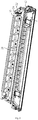
Fig. 1 illustrates a planar schematic structural diagram of a left-right door opening mechanism in a specific embodiment of the present invention; -
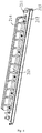
Fig. 2 illustrates a stereoscopic schematic structural diagram of a left-right door opening mechanism in a specific embodiment of the present invention; -
Fig. 3 illustrates an exploded schematic structural diagram of a left-right door opening mechanism in a specific embodiment of the present invention; -
Fig. 4 is a stereoscopic schematic structural diagram of a transmission bottom plate in a specific embodiment of the present invention; -
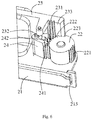
Fig. 5 illustrates a stereoscopic schematic structural diagram of a first gear, a second gear and a transmission rack in a specific embodiment of the present invention; -
Fig. 6 illustrates an assembly schematic structural diagram of a transmission module in a specific embodiment of the present invention; -
Fig. 7 illustrates a stereoscopic schematic structural diagram of a hinge bottom plate in a specific embodiment of the present invention; -
Fig. 8 illustrates a stereoscopic schematic structural diagram of a hinge in a specific embodiment of the present invention; -
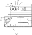
Fig. 9 illustrates a state diagram when the left-right door opening mechanism is locked from the left side in a specific embodiment of the present invention; and -
Fig. 10 illustrates a state diagram when the left-right door opening mechanism is opened from the left side in a specific embodiment of the present invention. - To make the objects, technical solutions and advantages of the present invention clearer, the specific embodiments of the present invention are described in detail with reference to the accompanying drawings. Examples of these preferred embodiments are given in the accompanying drawings. The embodiments of the present invention shown in the accompanying drawings and described based on the accompanying drawings are only exemplary and are not intended to limit the present invention.
- The terms "left", "right", "left side", "right side", and the like as used here, which denote spatial relative positions, describe the relationship of a component relative to another component in the accompanying drawings for the purpose of illustration. The terms of the spatial relative positions may be intended to include different orientations of the device in use or operation other than the orientations shown in the accompanying drawings. For example, the units that are described as being located on the "right side" of other units or features will be located on the "left side" of other units or features if the device in the accompanying drawings is turned upside down. Thus, the exemplary term "right side" can encompass both the orientations of left side and right side. The device may be otherwise oriented (rotated by 90 degrees or facing other directions) and the space-related descriptors used here are interpreted accordingly.
- As shown in
Fig. 1 , a left-right door opening mechanism in a specific embodiment of the present invention comprises a hinge module 100 arranged on a refrigerator door body and a transmission module 200 arranged on a refrigerator cabinet body. The hinge module 100 and the transmission module 200 are mounted by means of components such as hinges and gears provided on two ends. The hinge module 100 and the transmission module 200 each have at least one end that is rotatably fixed, such that the door of the refrigerator may be opened from the left side or the right side. - As shown in
Figs. 2 and3 , the transmission module 200 in the present embodiment comprises atransmission bottom plate 21, twofirst gears 22 oppositely arranged on the transmission bottom plate, atransmission rack 23 which is in transmission through the first gears, andsecond gears 24 which are in transmission with the first gears respectively. Thetransmission rack 23 is guided and limited by thesecond gears 24. The hinge module 100 comprises ahinge bottom plate 11 and twohinges 12 oppositely arranged on the hinge bottom plate. Thehinges 12 are in transmission with thefirst gears 22. When the twohinges 12 are respectively meshed with thefirst gears 22, the door body is locked. When thehinge 12 on one side is disengaged from thefirst gear 22 but the hinge on the other side is still meshed with the other first gear, the door body is opened. - The left-right door opening mechanism in the present embodiment will be described in detail below in conjunction with specific components in the hinge module and the transmission module.
- As shown in
Fig. 4 , the transmission module 200 in the present embodiment comprises an elongatedtransmission bottom plate 21. A first rotatingshaft 211 and a second rotatingshaft 212 are respectively arranged on the left and right sides of thetransmission bottom plate 21. The first rotatingshaft 211 is located outside the second rotatingshaft 212. Thefirst gear 22 and thesecond gear 24 are rotatably mounted on thetransmission bottom plate 21 by means of the first rotatingshaft 211 and the second rotatingshaft 212, respectively. In addition, thefirst gear 22 and thesecond gear 24 are meshed with each other. - As shown in
Fig. 5 , thefirst gear 22 is circular and is rotatably mounted on thetransmission bottom plate 21 by means of the first rotatingshaft 211. The first rotatingshaft 211 is mounted at a center position of thefirst gear 22. Thefirst gear 22 comprises afirst tooth portion 221 meshed with the corresponding hinge and asecond tooth portion 222 meshed with the corresponding second gear and the corresponding transmission rack. - It should be understood that the
first tooth portion 221 and thesecond tooth portion 222 which are separated from each other are arranged outside thefirst gear 22 in the present embodiment. In other embodiments, thefirst tooth portion 221 and thesecond tooth portion 222 may also be arranged as a whole, and the purpose of transmission with the hinge, the second gear and the transmission rack may also be achieved. - The
second gear 24 is arranged in a fan shape, and is rotatably mounted on thetransmission bottom plate 21 by means of the second rotatingshaft 212. The secondrotating shaft 212 is mounted at a non-center position of thesecond gear 24. Thesecond gear 24 comprises athird tooth portion 241 meshed with the first gear. Thethird tooth portion 241 is arranged on the fan-shaped surface of thesecond gear 24. A slidinggroove 242 which is in an approximately arc shape is also arranged on the top of thesecond gear 24. - In the present embodiment, the
second gear 24 is higher than thefirst gear 22, but the bottom surface of the slidinggroove 242 is arranged at the same height as the top surface of thefirst gear 22. Moreover, the slidinggroove 242 is configured to have an opening, so that the assembly of thetransmission rack 23 and thesecond gear 24 can be performed quickly. Of course, in other embodiments, the sliding groove may also be configured to have no opening, and the heights of thefirst gear 22 and thesecond gear 24 may also be equal or thefirst gear 22 is higher than thesecond gear 24, which will not be described here in detail. - The
transmission rack 23 is longitudinal. Afourth tooth portion 231 which is meshed with the corresponding first gear is arranged on each of the two ends of thetransmission rack 23. Thefourth tooth portion 231 and thesecond tooth portion 222 on thefirst gear 22 are meshed with each other. Further, the transmission rack is provided with a limitingmember 232 which is perpendicular to the top surface of thesecond gear 24. When the first gear and the second gear are meshed to rotate, the transmission rack rotates along with the first gear, and the limitingmember 232 on the transmission rack moves in the slidinggroove 242 on thesecond gear 24. - In the present embodiment, the
transmission rack 23 is higher than thefirst gear 22 and thesecond gear 24, such that the limitingmember 232 of thetransmission rack 23 may be vertically assembled into the slidinggroove 242 on thesecond gear 24. - Further, in order to keep the
transmission rack 23 and thefirst gear 22 fixed, thefirst gear 22 is further provided with anaccommodating groove 223 on the side of thesecond tooth portion 222. Thetransmission rack 23 is provided with a fixingportion 233 outside thefourth tooth portion 231. The fixingportion 233 has a shape corresponding to the shape of theaccommodating groove 223. After thetransmission rack 23 is meshed with thefirst gear 22 by means of thesecond tooth portion 222 and thefourth tooth portion 231, the fixingportion 233 is fixedly accommodated inside theaccommodating groove 223, thereby fixing the end part of the transmission rack. -
Fig. 6 illustrates an assembly schematic diagram of the transmission module. The assembly and transmission principle of the transmission module is specifically as follows. - The
first gear 22 and thesecond gear 24 are rotatably mounted at the end part of thetransmission bottom plate 21 respectively by means of the firstrotating shaft 211 and the secondrotating shaft 212. A pair offirst gear 22 andsecond gear 24 is arranged on each of the two sides of thetransmission bottom plate 21. Thefirst gear 22 and thesecond gear 24 are meshed with each other by means of thesecond tooth portion 222 and thesecond tooth portion 241. Thefirst gear 22 can drive thesecond gear 24 to rotate along the secondrotating shaft 212 while rotating along the firstrotating shaft 211. - Meanwhile, the
transmission rack 23 and the twofirst gears 22 are meshed with each other by means of thesecond tooth portion 222 and thefourth tooth portion 231, respectively. Thefirst gear 22 on one side, which is in rotation, can drive thetransmission rack 23 to move horizontally, so that the transmission rack can drive thefirst gear 22 on the other side to rotate in the same direction. In order to ensure the relative position of thetransmission rack 23 and thefirst gear 22, the fixingportion 233 at the end part of thetransmission rack 23 and theaccommodating groove 223 on thefirst gear 22 are used to limit thetransmission rack 23 and thefirst gear 22. - During the transmission of the
transmission rack 23, the limitingmember 232 on thetransmission rack 23 is always located in the slidinggroove 242 on thesecond gear 24 to ensure that thetransmission rack 23 is not disengaged from the transmission position. Because the second gear rotates around the second rotating shaft, and meanwhile the transmission rack is linearly driven, the shape of the slidinggroove 242 is substantially in an arc shape. In addition, the slidinggroove 242 is arranged between the second rotating shaft and the third tooth portion, thereby providing a sliding track for the limitingmember 232 on thetransmission rack 23. - Preferably, as shown in
Figs. 1 and3 , in the present embodiment, in order to limit a transmission line of thetransmission rack 23, a guidingslider 213 is further arranged on thetransmission bottom plate 21 and located between the two second gears. The guidingslider 213 is provided with a guidinggroove 214 for guiding the transmission rack in the transmission direction. In the present embodiment, the guidingslider 213 is fixed on thetransmission bottom plate 21 by means of a plurality of nuts. Of course, in other embodiments, the mounting manners, such as buckling may be adopted, or the transmission bottom plate and the guiding slider may be integrally formed, which will not be described here. - As shown in
Fig. 7 , the hinge module 100 in the present embodiment comprises an elongated hingebottom plate 11. Third rotatingshafts 111 which are symmetrically distributed are arranged on two ends of thehinge bottom plate 11 respectively. A hinge which is used for connecting the hinge bottom plate and the transmission module is rotatably mounted on each of the thirdrotating shafts 111. - As shown in
Fig. 8 , thehinge 12 comprises ahinge body 121 and anextension portion 122 which extends outwards from thehinge body 121. Thehinge body 121 is rotatably mounted on thehinge bottom plate 11. Afifth tooth portion 123 is arranged on the side of the end part of theextension portion 122. Thefifth tooth portion 123 on thehinge 12 and thefirst tooth portion 221 of thefirst gear 22 on thetransmission bottom plate 21 are meshed with each other. - When the user opens the door from one side, the hinge module on one side is pulled. The
hinge 12 on this side in this case moves outwards by means of thefifth tooth portion 123. Thefifth tooth portion 123 and thefirst tooth portion 221 are meshed with each other to drive thefirst gear 22 on the transmission module to rotate around the firstrotating shaft 211. After thehinge 12 moves outwards by a distance, thefifth tooth portion 123 and thefirst tooth portion 221 are separated from each other. That is, thehinge 12 and thefirst gear 22 are separated from each other, thefirst gear 22 stops rotating, and the hinge and the hinge body on the other side are rotatably arranged to achieve the purpose of opening the door from one side. - Further, as shown in
Fig. 6 , in the present embodiment, aslot 215 is fixedly arranged on each of the two ends of thetransmission bottom plate 21 and used for limiting the extension portion. Theslots 215 are formed in a manner of buckling. Thehinge 12 moves in a direction (perpendicular to a movement direction of the transmission rack) of theslot 215 while moving relative to thefirst gear 22. - As shown in
Figs. 9 and10 , the present embodiment will be further described by taking the door which is opened from the left side as an example. - By reference to
Fig. 9 and as shown inFigs. 1 to 8 , the left-right door opening mechanism is in a locked state. The hinge module is clamped with the transmission module. Thehinge 12 is rotatably mounted on thehinge bottom plate 11. Thefirst gear 22, thesecond gear 24 and thetransmission rack 23 are mounted on thetransmission bottom plate 21. Thehinge 12 on the left side is meshed with thefirst tooth portion 221 on thefirst gear 22 by means of thefifth tooth portion 123 at the front end. Thesecond tooth portion 222 of thefirst gear 22 is meshed with thethird tooth portion 221 of thesecond gear 24. Meanwhile, thefourth tooth portion 231 at the left end of thetransmission rack 23 is not meshed with thefirst tooth portion 221 of thefirst gear 22. The fixingportion 233 at the left end of thetransmission rack 23 is located in theaccommodating groove 223 of thefirst gear 22. The limitingmember 232 of thetransmission rack 23 is vertically assembled in the slidinggroove 242 on thesecond gear 24. Similarly, the assembly relationship on the right side of the left-right door opening mechanism is symmetric with that on the left side, and will not be described here again. - When the door is opened from the left side, the
hinge bottom plate 11 on the left side is pulled to drive thehinge 12 on the left side to move outwards. Thehinge 12 on the left side is meshed with thefirst tooth portion 221 by means of thefifth tooth portion 123 to drive thefirst gear 22 to move anticlockwise. Thesecond tooth portion 222 on thefirst gear 22 and thefourth tooth portion 231 on thetransmission rack 23 are meshed to further drive thetransmission rack 23 to move leftwards. Meanwhile, thesecond tooth portion 222 of thefirst gear 22 and thethird tooth portion 241 of thesecond gear 24 are meshed with each other. Thefirst gear 22 may drive thesecond gear 24 to rotate clockwise. The limitingmember 232 on thetransmission rack 23 moves leftwards along the slidinggroove 242. - When the
transmission rack 23 moves leftwards, thefourth tooth portion 231 on the right side of thetransmission rack 23 drives thefirst gear 22 on the right side to rotate clockwise. Thefirst gear 22 simultaneously drives thesecond gear 24 on the right side to rotate clockwise, and thehinge 12 on the right side moves inwards. - It can thus be seen that the
hinge 12 on the left side gradually moves outwards till thehinge 12 is disengaged from thefirst gear 22 on the left side. The left-right door opening mechanism on the left side is in an opened state, and the structure thereof is shown inFig. 10 . Thehinge 12 on the right side in this case gradually moves inwardly, and is further locked with thefirst gear 22 on the right side. The third rotating shaft on the hinge bottom plate on the right side serves as a central shaft for the refrigerator door body to rotate. - When the door is locked from the left side, the left side of the door body is pushed. The
hinge 12 on the left side moves inwards until thefirst gear 22 and thehinge 12 are gradually meshed. The transmission direction of thefirst gear 22, thesecond gear 24, and thetransmission rack 23 on the left side is opposite to that when the door is opened. Thetransmission rack 23 gradually moves rightwards until the refrigerator door body is fitted to the refrigerator cabinet body. The state of the left-right door opening mechanism in this case is restored to the state shown inFigs. 1 and9 . - Similarly, when the door is opened from the right side by the left-right door opening mechanism, the hinge on the right side moves outwards. The hinge on the left side in this case will move inwards reversely till being gradually locked. The third rotating shaft on the hinge bottom plate on the left side serves as a central shaft for the refrigerator door body to rotate. When the lock is locked from the right side, the hinge on the right side moves inwards, and the transmission rack gradually moves leftwards till being restored to the locked state. The transmission relationship of the left-right door opening mechanism when the door is opened or locked from the right side is similar to that of opening or locking the door from the left side, and will not be described here.
- The left-right door opening mechanism in the present embodiment is described by taking a refrigerator as an example. In other embodiments, the left-right door opening mechanism may be applied to any device comprising a door body and a refrigerator body, such as a wine cabinet, etc., and will not be described in detail here.
- As can be seen from the above technical solution, the present invention has the following beneficial effects.
- The rotating shaft is arranged on the door body, and the door can be opened from the left side or the right side, without making any adjustment.
- It is ensured that the door opening and closing process is smooth and free of blocking and impact noise. The door body is unlikely to fall off during the opening and closing process, and provides an excellent use experience for a user.
- It should be understood that although the description is described based on the embodiments, not every embodiment includes only one independent technical solution. This statement manner of the description is only for clarity. Those skilled in the art should treat the description as a whole, and technical solutions in all of the embodiments may also be properly combined to form other embodiments that will be understood by those skilled in the art.
- The above detailed description only aims to specifically illustrate the feasible embodiments of the present invention, and is not intended to limit the protection scope of the present invention. Equivalent embodiments or modifications thereof made without departing from the spirit of the present invention shall fall within the protection scope of the present invention.
Claims (10)
- A left-right door opening mechanism, comprising a hinge module arranged on a refrigerator door body and a transmission module arranged on a refrigerator cabinet body, wherein the transmission module comprises a transmission bottom plate, two first gears oppositely arranged on the transmission bottom plate, a transmission rack which is in transmission through the first gears, and second gears which are in transmission with the first gears respectively; the transmission rack is guided and limited by the second gears; the hinge module comprises a hinge bottom plate and two hinges oppositely arranged on the hinge bottom plate; the hinges are in transmission with the first gears; when the two hinges are respectively meshed with the first gears, the door body is locked; when the hinge on one side is disengaged from the first gear but the hinge on the other side is still meshed with the other first gear, the door body is opened.
- The left-right door opening mechanism according to claim 1, wherein the hinge and the second gear are located on two sides of each of the first gears, and the second gear is located inside each of the two first gears; the hinge is located outside each of the first gears.
- The left-right door opening mechanism according to claim 2, wherein the first gear is rotatably mounted on the transmission bottom plate by means of a first rotating shaft; the first gear comprises a first tooth portion meshed with the corresponding hinge, and a second tooth portion meshed with the corresponding second gear and the corresponding transmission rack.
- The left-right door opening mechanism according to claim 2, wherein the second gear is rotatably mounted on the transmission bottom plate by means of a second rotating shaft; the second gear comprises a third tooth portion meshed with the first gear; the second rotating shaft is located at a non-center position of the second gear.
- The left-right door opening mechanism according to claim 4, wherein a limiting member is arranged on the transmission rack; a sliding groove for accommodating the limiting member is arranged at the upper part of the second gear.
- The left-right door opening mechanism according to claim 2, wherein a fourth tooth portion which is meshed with the first gear is arranged on each of the two ends of the transmission rack; a fixing portion is further arranged outside the fourth tooth portion; the first gear is provided with an accommodating groove for accommodating the fixing portion.
- The left-right door opening mechanism according to claim 2, wherein the hinge is rotatably mounted on the hinge bottom plate by means of a third rotating shaft; the hinge comprises a fifth tooth portion which is meshed with the corresponding first gear.
- The left-right door opening mechanism according to claim 7, wherein the hinge comprises a hinge body and an extension portion which extends outwards from the hinge body; the hinge body is rotatably mounted on the hinge bottom plate; the fifth tooth portion is arranged at the end part of the extension portion; the transmission bottom plate is fixedly provided with a slot for limiting the extension portion.
- The left-right door opening mechanism according to claim 1, wherein a guiding slider is arranged on the transmission bottom plate; the guiding slider is provided with a guiding groove used for guiding the transmission rack along a transmission direction.
- A refrigerator, comprising the left-right door opening mechanism according to any one of claims 1 to 9.
Applications Claiming Priority (2)
| Application Number | Priority Date | Filing Date | Title |
|---|---|---|---|
| CN201610377865.9A CN106016927B (en) | 2016-05-31 | 2016-05-31 | Cross opening door mechanism and refrigerator |
| PCT/CN2016/112820 WO2017206501A1 (en) | 2016-05-31 | 2016-12-29 | Cross opening door mechanism and refrigerator |
Publications (3)
| Publication Number | Publication Date |
|---|---|
| EP3467412A1 true EP3467412A1 (en) | 2019-04-10 |
| EP3467412A4 EP3467412A4 (en) | 2019-06-12 |
| EP3467412B1 EP3467412B1 (en) | 2022-08-10 |
Family
ID=57092851
Family Applications (1)
| Application Number | Title | Priority Date | Filing Date |
|---|---|---|---|
| EP16903881.7A Active EP3467412B1 (en) | 2016-05-31 | 2016-12-29 | Cross opening door mechanism and refrigerator |
Country Status (6)
| Country | Link |
|---|---|
| US (1) | US10451334B2 (en) |
| EP (1) | EP3467412B1 (en) |
| CN (1) | CN106016927B (en) |
| AU (1) | AU2016408809B2 (en) |
| NZ (1) | NZ748096A (en) |
| WO (1) | WO2017206501A1 (en) |
Families Citing this family (8)
| Publication number | Priority date | Publication date | Assignee | Title |
|---|---|---|---|---|
| CN106016927B (en) * | 2016-05-31 | 2018-07-13 | 青岛海尔股份有限公司 | Cross opening door mechanism and refrigerator |
| CN108590404A (en) * | 2018-05-22 | 2018-09-28 | 张卫 | Reversible door hinge |
| CN113227686B (en) * | 2018-12-21 | 2023-04-25 | 伊莱克斯电器股份公司 | Wine cooler with reversible door |
| CN110037586A (en) * | 2019-04-22 | 2019-07-23 | 深圳厨艺科技有限公司 | A kind of locking mechanism for kitchen appliance |
| KR20210106270A (en) * | 2020-02-20 | 2021-08-30 | 삼성전자주식회사 | Refrigerator |
| CN113431457B (en) * | 2021-08-10 | 2023-10-13 | 江苏玖星精密科技集团有限公司 | A gear-driven monorail embedded hinge |
| CN114294895B (en) * | 2021-12-20 | 2023-09-26 | 创维电器股份有限公司 | Side-opening type left-right arbitrary door opening structure of refrigerator |
| US12006752B1 (en) * | 2023-02-21 | 2024-06-11 | Hangzhou Jinsong Euna Electrical Appliances Co., Ltd. | Door limiting mechanism and electric appliance cabinet |
Family Cites Families (23)
| Publication number | Priority date | Publication date | Assignee | Title |
|---|---|---|---|---|
| DE3215607A1 (en) * | 1982-04-27 | 1983-10-27 | Paul Hettich & Co, 4983 Kirchlengern | CABINET WITH A DOUBLE DOOR CONSISTING OF AN INTERIOR AND OUTDOOR. |
| US4495673A (en) * | 1982-09-29 | 1985-01-29 | Whirlpool Corporation | Double-acting refrigerator door hinge with dual latch members |
| US4503582A (en) * | 1982-09-29 | 1985-03-12 | Whirlpool Corporation | Double-acting refrigerator door hinge and sliding lock-bolt |
| US4947583A (en) * | 1988-05-10 | 1990-08-14 | Sharp Kabushiki Kaisha | Opening/closing device of a door member |
| US5064255A (en) * | 1988-05-10 | 1991-11-12 | Sharp Kabushiki Kaisha | Opening/closing device of a door member |
| JPH04148180A (en) * | 1990-10-05 | 1992-05-21 | Hoshizaki Electric Co Ltd | Both left-and-right opening door structure for box body |
| KR0152116B1 (en) * | 1994-04-29 | 1998-11-02 | 김광호 | Doa of the refrigerator |
| KR960001395A (en) * | 1994-06-16 | 1996-01-25 | 박병기 | Both sides open door opening and closing device |
| US5829197A (en) * | 1995-12-02 | 1998-11-03 | Samsung Electronics Co., Ltd. | Manually actuable apparatus enabling a door to be selectively hinged at either side |
| KR19990013174A (en) * | 1997-07-31 | 1999-02-25 | 배순훈 | Refrigerator with opening and closing doors |
| US6000771A (en) * | 1997-09-26 | 1999-12-14 | Thetford Corporation | RV refrigerator with swinging closure door capable of being opened from both left and right sides |
| TW521142B (en) * | 2001-03-13 | 2003-02-21 | Sharp Kk | Cam mechanism and door opening/closing mechanism |
| KR20060000340A (en) * | 2004-06-28 | 2006-01-06 | 삼성전자주식회사 | Refrigerator |
| JP2006057904A (en) | 2004-08-19 | 2006-03-02 | Mitsubishi Electric Corp | refrigerator |
| KR200400437Y1 (en) * | 2005-08-08 | 2005-11-08 | 이근원 | both hinge |
| US20080048539A1 (en) * | 2006-08-24 | 2008-02-28 | Beek Jacco V | Refrigerator capable of being opened from opposite sides |
| KR101424554B1 (en) * | 2007-01-23 | 2014-07-31 | 삼성전자 주식회사 | A bidirectional door unit and a refrigerator including the same |
| KR101462181B1 (en) * | 2008-12-05 | 2014-11-21 | 삼성전자주식회사 | Microwave Oven |
| CN202692585U (en) * | 2012-07-10 | 2013-01-23 | 泰州乐金电子冷机有限公司 | Refrigerator with door opened in two ways |
| CN104344660B (en) * | 2013-11-29 | 2017-01-11 | 海尔集团公司 | Two-way door-opening device and refrigerator with same |
| CN105509396B (en) * | 2015-12-28 | 2018-05-29 | 青岛海尔股份有限公司 | Refrigerator |
| CN106052268B (en) * | 2016-05-31 | 2018-10-12 | 青岛海尔股份有限公司 | Cross opening door mechanism and refrigerator |
| CN106016927B (en) | 2016-05-31 | 2018-07-13 | 青岛海尔股份有限公司 | Cross opening door mechanism and refrigerator |
-
2016
- 2016-05-31 CN CN201610377865.9A patent/CN106016927B/en active Active
- 2016-12-29 EP EP16903881.7A patent/EP3467412B1/en active Active
- 2016-12-29 WO PCT/CN2016/112820 patent/WO2017206501A1/en not_active Ceased
- 2016-12-29 NZ NZ748096A patent/NZ748096A/en unknown
- 2016-12-29 AU AU2016408809A patent/AU2016408809B2/en active Active
- 2016-12-29 US US16/302,100 patent/US10451334B2/en active Active
Also Published As
| Publication number | Publication date |
|---|---|
| NZ748096A (en) | 2020-05-29 |
| AU2016408809A1 (en) | 2018-11-22 |
| CN106016927B (en) | 2018-07-13 |
| CN106016927A (en) | 2016-10-12 |
| AU2016408809B2 (en) | 2020-01-30 |
| EP3467412A4 (en) | 2019-06-12 |
| US20190145695A1 (en) | 2019-05-16 |
| WO2017206501A1 (en) | 2017-12-07 |
| US10451334B2 (en) | 2019-10-22 |
| EP3467412B1 (en) | 2022-08-10 |
Similar Documents
| Publication | Publication Date | Title |
|---|---|---|
| EP3467412B1 (en) | Cross opening door mechanism and refrigerator | |
| EP3467413B1 (en) | Reversible door opening mechanism and refrigerator | |
| US20150197976A1 (en) | Double-pivot synchronization mechanism for opening and closing two leaves | |
| JP6815018B2 (en) | Guide device for sliding doors | |
| EP3323587A1 (en) | A bottle blowing machine | |
| CN106288620A (en) | Cross opening door mechanism and refrigerator | |
| JP6358804B2 (en) | Automatic opening and closing device for joinery | |
| CN106766586B (en) | Left-right door opening mechanism and refrigerator | |
| EP2977180A1 (en) | Link mechanism for opening and closing die and positioning bottom die by single shaft | |
| CN108286862A (en) | Insert hinge device | |
| CN108426401B (en) | refrigerator | |
| CN209604413U (en) | With dynamic formula concealed type pivot device | |
| JP5421801B2 (en) | Opening device | |
| EP2574869A1 (en) | Hinge unit for refrigerator cabinet doors | |
| JP2015175113A (en) | Automatic switchgear of fitting | |
| CN210036017U (en) | Automatic drawer | |
| CN105109389B (en) | A kind of automobile-used box body | |
| CN108252601A (en) | Insert hinge device | |
| CN208633680U (en) | A kind of angle driver and door and window | |
| US10653024B2 (en) | Door opening and closing mechanism | |
| CN217982485U (en) | Machine cabinet | |
| JP4152867B2 (en) | Sliding door closing device in the cabinet. | |
| JP6094757B2 (en) | Finger pinching prevention device and cabinet equipped with finger pinching prevention device | |
| CN115886458A (en) | Drawer cabinet | |
| KR101114479B1 (en) | self-closing type rack apparatus |
Legal Events
| Date | Code | Title | Description |
|---|---|---|---|
| STAA | Information on the status of an ep patent application or granted ep patent |
Free format text: STATUS: THE INTERNATIONAL PUBLICATION HAS BEEN MADE |
|
| PUAI | Public reference made under article 153(3) epc to a published international application that has entered the european phase |
Free format text: ORIGINAL CODE: 0009012 |
|
| STAA | Information on the status of an ep patent application or granted ep patent |
Free format text: STATUS: REQUEST FOR EXAMINATION WAS MADE |
|
| 17P | Request for examination filed |
Effective date: 20181121 |
|
| AK | Designated contracting states |
Kind code of ref document: A1 Designated state(s): AL AT BE BG CH CY CZ DE DK EE ES FI FR GB GR HR HU IE IS IT LI LT LU LV MC MK MT NL NO PL PT RO RS SE SI SK SM TR |
|
| AX | Request for extension of the european patent |
Extension state: BA ME |
|
| A4 | Supplementary search report drawn up and despatched |
Effective date: 20190515 |
|
| RIC1 | Information provided on ipc code assigned before grant |
Ipc: F25D 23/02 20060101AFI20190509BHEP Ipc: E05D 15/50 20060101ALI20190509BHEP |
|
| DAV | Request for validation of the european patent (deleted) | ||
| DAX | Request for extension of the european patent (deleted) | ||
| STAA | Information on the status of an ep patent application or granted ep patent |
Free format text: STATUS: EXAMINATION IS IN PROGRESS |
|
| 17Q | First examination report despatched |
Effective date: 20200325 |
|
| GRAP | Despatch of communication of intention to grant a patent |
Free format text: ORIGINAL CODE: EPIDOSNIGR1 |
|
| STAA | Information on the status of an ep patent application or granted ep patent |
Free format text: STATUS: GRANT OF PATENT IS INTENDED |
|
| GRAJ | Information related to disapproval of communication of intention to grant by the applicant or resumption of examination proceedings by the epo deleted |
Free format text: ORIGINAL CODE: EPIDOSDIGR1 |
|
| GRAP | Despatch of communication of intention to grant a patent |
Free format text: ORIGINAL CODE: EPIDOSNIGR1 |
|
| GRAJ | Information related to disapproval of communication of intention to grant by the applicant or resumption of examination proceedings by the epo deleted |
Free format text: ORIGINAL CODE: EPIDOSDIGR1 |
|
| INTG | Intention to grant announced |
Effective date: 20220114 |
|
| GRAP | Despatch of communication of intention to grant a patent |
Free format text: ORIGINAL CODE: EPIDOSNIGR1 |
|
| INTG | Intention to grant announced |
Effective date: 20220203 |
|
| INTG | Intention to grant announced |
Effective date: 20220211 |
|
| INTG | Intention to grant announced |
Effective date: 20220311 |
|
| GRAS | Grant fee paid |
Free format text: ORIGINAL CODE: EPIDOSNIGR3 |
|
| GRAA | (expected) grant |
Free format text: ORIGINAL CODE: 0009210 |
|
| STAA | Information on the status of an ep patent application or granted ep patent |
Free format text: STATUS: THE PATENT HAS BEEN GRANTED |
|
| AK | Designated contracting states |
Kind code of ref document: B1 Designated state(s): AL AT BE BG CH CY CZ DE DK EE ES FI FR GB GR HR HU IE IS IT LI LT LU LV MC MK MT NL NO PL PT RO RS SE SI SK SM TR |
|
| REG | Reference to a national code |
Ref country code: AT Ref legal event code: REF Ref document number: 1510834 Country of ref document: AT Kind code of ref document: T Effective date: 20220815 Ref country code: CH Ref legal event code: EP |
|
| REG | Reference to a national code |
Ref country code: IE Ref legal event code: FG4D |
|
| REG | Reference to a national code |
Ref country code: DE Ref legal event code: R096 Ref document number: 602016074274 Country of ref document: DE |
|
| REG | Reference to a national code |
Ref country code: NL Ref legal event code: MP Effective date: 20220810 |
|
| REG | Reference to a national code |
Ref country code: LT Ref legal event code: MG9D |
|
| PG25 | Lapsed in a contracting state [announced via postgrant information from national office to epo] |
Ref country code: SE Free format text: LAPSE BECAUSE OF FAILURE TO SUBMIT A TRANSLATION OF THE DESCRIPTION OR TO PAY THE FEE WITHIN THE PRESCRIBED TIME-LIMIT Effective date: 20220810 Ref country code: RS Free format text: LAPSE BECAUSE OF FAILURE TO SUBMIT A TRANSLATION OF THE DESCRIPTION OR TO PAY THE FEE WITHIN THE PRESCRIBED TIME-LIMIT Effective date: 20220810 Ref country code: PT Free format text: LAPSE BECAUSE OF FAILURE TO SUBMIT A TRANSLATION OF THE DESCRIPTION OR TO PAY THE FEE WITHIN THE PRESCRIBED TIME-LIMIT Effective date: 20221212 Ref country code: NO Free format text: LAPSE BECAUSE OF FAILURE TO SUBMIT A TRANSLATION OF THE DESCRIPTION OR TO PAY THE FEE WITHIN THE PRESCRIBED TIME-LIMIT Effective date: 20221110 Ref country code: NL Free format text: LAPSE BECAUSE OF FAILURE TO SUBMIT A TRANSLATION OF THE DESCRIPTION OR TO PAY THE FEE WITHIN THE PRESCRIBED TIME-LIMIT Effective date: 20220810 Ref country code: LV Free format text: LAPSE BECAUSE OF FAILURE TO SUBMIT A TRANSLATION OF THE DESCRIPTION OR TO PAY THE FEE WITHIN THE PRESCRIBED TIME-LIMIT Effective date: 20220810 Ref country code: LT Free format text: LAPSE BECAUSE OF FAILURE TO SUBMIT A TRANSLATION OF THE DESCRIPTION OR TO PAY THE FEE WITHIN THE PRESCRIBED TIME-LIMIT Effective date: 20220810 Ref country code: FI Free format text: LAPSE BECAUSE OF FAILURE TO SUBMIT A TRANSLATION OF THE DESCRIPTION OR TO PAY THE FEE WITHIN THE PRESCRIBED TIME-LIMIT Effective date: 20220810 |
|
| REG | Reference to a national code |
Ref country code: AT Ref legal event code: MK05 Ref document number: 1510834 Country of ref document: AT Kind code of ref document: T Effective date: 20220810 |
|
| PG25 | Lapsed in a contracting state [announced via postgrant information from national office to epo] |
Ref country code: PL Free format text: LAPSE BECAUSE OF FAILURE TO SUBMIT A TRANSLATION OF THE DESCRIPTION OR TO PAY THE FEE WITHIN THE PRESCRIBED TIME-LIMIT Effective date: 20220810 Ref country code: IS Free format text: LAPSE BECAUSE OF FAILURE TO SUBMIT A TRANSLATION OF THE DESCRIPTION OR TO PAY THE FEE WITHIN THE PRESCRIBED TIME-LIMIT Effective date: 20221210 Ref country code: HR Free format text: LAPSE BECAUSE OF FAILURE TO SUBMIT A TRANSLATION OF THE DESCRIPTION OR TO PAY THE FEE WITHIN THE PRESCRIBED TIME-LIMIT Effective date: 20220810 Ref country code: GR Free format text: LAPSE BECAUSE OF FAILURE TO SUBMIT A TRANSLATION OF THE DESCRIPTION OR TO PAY THE FEE WITHIN THE PRESCRIBED TIME-LIMIT Effective date: 20221111 |
|
| PG25 | Lapsed in a contracting state [announced via postgrant information from national office to epo] |
Ref country code: SM Free format text: LAPSE BECAUSE OF FAILURE TO SUBMIT A TRANSLATION OF THE DESCRIPTION OR TO PAY THE FEE WITHIN THE PRESCRIBED TIME-LIMIT Effective date: 20220810 Ref country code: RO Free format text: LAPSE BECAUSE OF FAILURE TO SUBMIT A TRANSLATION OF THE DESCRIPTION OR TO PAY THE FEE WITHIN THE PRESCRIBED TIME-LIMIT Effective date: 20220810 Ref country code: ES Free format text: LAPSE BECAUSE OF FAILURE TO SUBMIT A TRANSLATION OF THE DESCRIPTION OR TO PAY THE FEE WITHIN THE PRESCRIBED TIME-LIMIT Effective date: 20220810 Ref country code: DK Free format text: LAPSE BECAUSE OF FAILURE TO SUBMIT A TRANSLATION OF THE DESCRIPTION OR TO PAY THE FEE WITHIN THE PRESCRIBED TIME-LIMIT Effective date: 20220810 Ref country code: CZ Free format text: LAPSE BECAUSE OF FAILURE TO SUBMIT A TRANSLATION OF THE DESCRIPTION OR TO PAY THE FEE WITHIN THE PRESCRIBED TIME-LIMIT Effective date: 20220810 Ref country code: AT Free format text: LAPSE BECAUSE OF FAILURE TO SUBMIT A TRANSLATION OF THE DESCRIPTION OR TO PAY THE FEE WITHIN THE PRESCRIBED TIME-LIMIT Effective date: 20220810 |
|
| REG | Reference to a national code |
Ref country code: DE Ref legal event code: R097 Ref document number: 602016074274 Country of ref document: DE |
|
| PG25 | Lapsed in a contracting state [announced via postgrant information from national office to epo] |
Ref country code: SK Free format text: LAPSE BECAUSE OF FAILURE TO SUBMIT A TRANSLATION OF THE DESCRIPTION OR TO PAY THE FEE WITHIN THE PRESCRIBED TIME-LIMIT Effective date: 20220810 Ref country code: EE Free format text: LAPSE BECAUSE OF FAILURE TO SUBMIT A TRANSLATION OF THE DESCRIPTION OR TO PAY THE FEE WITHIN THE PRESCRIBED TIME-LIMIT Effective date: 20220810 |
|
| PLBE | No opposition filed within time limit |
Free format text: ORIGINAL CODE: 0009261 |
|
| STAA | Information on the status of an ep patent application or granted ep patent |
Free format text: STATUS: NO OPPOSITION FILED WITHIN TIME LIMIT |
|
| PG25 | Lapsed in a contracting state [announced via postgrant information from national office to epo] |
Ref country code: AL Free format text: LAPSE BECAUSE OF FAILURE TO SUBMIT A TRANSLATION OF THE DESCRIPTION OR TO PAY THE FEE WITHIN THE PRESCRIBED TIME-LIMIT Effective date: 20220810 |
|
| 26N | No opposition filed |
Effective date: 20230511 |
|
| REG | Reference to a national code |
Ref country code: CH Ref legal event code: PL |
|
| REG | Reference to a national code |
Ref country code: BE Ref legal event code: MM Effective date: 20221231 |
|
| PG25 | Lapsed in a contracting state [announced via postgrant information from national office to epo] |
Ref country code: SI Free format text: LAPSE BECAUSE OF FAILURE TO SUBMIT A TRANSLATION OF THE DESCRIPTION OR TO PAY THE FEE WITHIN THE PRESCRIBED TIME-LIMIT Effective date: 20220810 Ref country code: LU Free format text: LAPSE BECAUSE OF NON-PAYMENT OF DUE FEES Effective date: 20221229 |
|
| PG25 | Lapsed in a contracting state [announced via postgrant information from national office to epo] |
Ref country code: LI Free format text: LAPSE BECAUSE OF NON-PAYMENT OF DUE FEES Effective date: 20221231 Ref country code: IE Free format text: LAPSE BECAUSE OF NON-PAYMENT OF DUE FEES Effective date: 20221229 Ref country code: CH Free format text: LAPSE BECAUSE OF NON-PAYMENT OF DUE FEES Effective date: 20221231 |
|
| PG25 | Lapsed in a contracting state [announced via postgrant information from national office to epo] |
Ref country code: BE Free format text: LAPSE BECAUSE OF NON-PAYMENT OF DUE FEES Effective date: 20221231 |
|
| PG25 | Lapsed in a contracting state [announced via postgrant information from national office to epo] |
Ref country code: HU Free format text: LAPSE BECAUSE OF FAILURE TO SUBMIT A TRANSLATION OF THE DESCRIPTION OR TO PAY THE FEE WITHIN THE PRESCRIBED TIME-LIMIT; INVALID AB INITIO Effective date: 20161229 |
|
| PG25 | Lapsed in a contracting state [announced via postgrant information from national office to epo] |
Ref country code: CY Free format text: LAPSE BECAUSE OF FAILURE TO SUBMIT A TRANSLATION OF THE DESCRIPTION OR TO PAY THE FEE WITHIN THE PRESCRIBED TIME-LIMIT Effective date: 20220810 |
|
| PG25 | Lapsed in a contracting state [announced via postgrant information from national office to epo] |
Ref country code: MK Free format text: LAPSE BECAUSE OF FAILURE TO SUBMIT A TRANSLATION OF THE DESCRIPTION OR TO PAY THE FEE WITHIN THE PRESCRIBED TIME-LIMIT Effective date: 20220810 |
|
| PG25 | Lapsed in a contracting state [announced via postgrant information from national office to epo] |
Ref country code: MC Free format text: LAPSE BECAUSE OF FAILURE TO SUBMIT A TRANSLATION OF THE DESCRIPTION OR TO PAY THE FEE WITHIN THE PRESCRIBED TIME-LIMIT Effective date: 20220810 |
|
| PG25 | Lapsed in a contracting state [announced via postgrant information from national office to epo] |
Ref country code: TR Free format text: LAPSE BECAUSE OF FAILURE TO SUBMIT A TRANSLATION OF THE DESCRIPTION OR TO PAY THE FEE WITHIN THE PRESCRIBED TIME-LIMIT Effective date: 20220810 Ref country code: MC Free format text: LAPSE BECAUSE OF FAILURE TO SUBMIT A TRANSLATION OF THE DESCRIPTION OR TO PAY THE FEE WITHIN THE PRESCRIBED TIME-LIMIT Effective date: 20220810 |
|
| PG25 | Lapsed in a contracting state [announced via postgrant information from national office to epo] |
Ref country code: BG Free format text: LAPSE BECAUSE OF FAILURE TO SUBMIT A TRANSLATION OF THE DESCRIPTION OR TO PAY THE FEE WITHIN THE PRESCRIBED TIME-LIMIT Effective date: 20220810 |
|
| PG25 | Lapsed in a contracting state [announced via postgrant information from national office to epo] |
Ref country code: MT Free format text: LAPSE BECAUSE OF FAILURE TO SUBMIT A TRANSLATION OF THE DESCRIPTION OR TO PAY THE FEE WITHIN THE PRESCRIBED TIME-LIMIT Effective date: 20220810 |
|
| PGFP | Annual fee paid to national office [announced via postgrant information from national office to epo] |
Ref country code: GB Payment date: 20251229 Year of fee payment: 10 |
|
| PGFP | Annual fee paid to national office [announced via postgrant information from national office to epo] |
Ref country code: IT Payment date: 20251210 Year of fee payment: 10 |
|
| PGFP | Annual fee paid to national office [announced via postgrant information from national office to epo] |
Ref country code: FR Payment date: 20251230 Year of fee payment: 10 |
|
| PGFP | Annual fee paid to national office [announced via postgrant information from national office to epo] |
Ref country code: DE Payment date: 20251231 Year of fee payment: 10 |