EP3467393A1 - Air conditioner - Google Patents
Air conditioner Download PDFInfo
- Publication number
- EP3467393A1 EP3467393A1 EP16903187.9A EP16903187A EP3467393A1 EP 3467393 A1 EP3467393 A1 EP 3467393A1 EP 16903187 A EP16903187 A EP 16903187A EP 3467393 A1 EP3467393 A1 EP 3467393A1
- Authority
- EP
- European Patent Office
- Prior art keywords
- cooling
- indoor units
- unit
- indoor
- units
- Prior art date
- Legal status (The legal status is an assumption and is not a legal conclusion. Google has not performed a legal analysis and makes no representation as to the accuracy of the status listed.)
- Granted
Links
Images



Classifications
-
- F—MECHANICAL ENGINEERING; LIGHTING; HEATING; WEAPONS; BLASTING
- F25—REFRIGERATION OR COOLING; COMBINED HEATING AND REFRIGERATION SYSTEMS; HEAT PUMP SYSTEMS; MANUFACTURE OR STORAGE OF ICE; LIQUEFACTION SOLIDIFICATION OF GASES
- F25B—REFRIGERATION MACHINES, PLANTS OR SYSTEMS; COMBINED HEATING AND REFRIGERATION SYSTEMS; HEAT PUMP SYSTEMS
- F25B13/00—Compression machines, plants or systems, with reversible cycle
-
- F—MECHANICAL ENGINEERING; LIGHTING; HEATING; WEAPONS; BLASTING
- F24—HEATING; RANGES; VENTILATING
- F24F—AIR-CONDITIONING; AIR-HUMIDIFICATION; VENTILATION; USE OF AIR CURRENTS FOR SCREENING
- F24F11/00—Control or safety arrangements
- F24F11/89—Arrangement or mounting of control or safety devices
-
- F—MECHANICAL ENGINEERING; LIGHTING; HEATING; WEAPONS; BLASTING
- F25—REFRIGERATION OR COOLING; COMBINED HEATING AND REFRIGERATION SYSTEMS; HEAT PUMP SYSTEMS; MANUFACTURE OR STORAGE OF ICE; LIQUEFACTION SOLIDIFICATION OF GASES
- F25B—REFRIGERATION MACHINES, PLANTS OR SYSTEMS; COMBINED HEATING AND REFRIGERATION SYSTEMS; HEAT PUMP SYSTEMS
- F25B49/00—Arrangement or mounting of control or safety devices
- F25B49/02—Arrangement or mounting of control or safety devices for compression type machines, plants or systems
- F25B49/022—Compressor control arrangements
-
- F—MECHANICAL ENGINEERING; LIGHTING; HEATING; WEAPONS; BLASTING
- F25—REFRIGERATION OR COOLING; COMBINED HEATING AND REFRIGERATION SYSTEMS; HEAT PUMP SYSTEMS; MANUFACTURE OR STORAGE OF ICE; LIQUEFACTION SOLIDIFICATION OF GASES
- F25B—REFRIGERATION MACHINES, PLANTS OR SYSTEMS; COMBINED HEATING AND REFRIGERATION SYSTEMS; HEAT PUMP SYSTEMS
- F25B2313/00—Compression machines, plants or systems with reversible cycle not otherwise provided for
- F25B2313/023—Compression machines, plants or systems with reversible cycle not otherwise provided for using multiple indoor units
- F25B2313/0233—Compression machines, plants or systems with reversible cycle not otherwise provided for using multiple indoor units in parallel arrangements
-
- F—MECHANICAL ENGINEERING; LIGHTING; HEATING; WEAPONS; BLASTING
- F25—REFRIGERATION OR COOLING; COMBINED HEATING AND REFRIGERATION SYSTEMS; HEAT PUMP SYSTEMS; MANUFACTURE OR STORAGE OF ICE; LIQUEFACTION SOLIDIFICATION OF GASES
- F25B—REFRIGERATION MACHINES, PLANTS OR SYSTEMS; COMBINED HEATING AND REFRIGERATION SYSTEMS; HEAT PUMP SYSTEMS
- F25B2313/00—Compression machines, plants or systems with reversible cycle not otherwise provided for
- F25B2313/025—Compression machines, plants or systems with reversible cycle not otherwise provided for using multiple outdoor units
- F25B2313/0253—Compression machines, plants or systems with reversible cycle not otherwise provided for using multiple outdoor units in parallel arrangements
-
- F—MECHANICAL ENGINEERING; LIGHTING; HEATING; WEAPONS; BLASTING
- F25—REFRIGERATION OR COOLING; COMBINED HEATING AND REFRIGERATION SYSTEMS; HEAT PUMP SYSTEMS; MANUFACTURE OR STORAGE OF ICE; LIQUEFACTION SOLIDIFICATION OF GASES
- F25B—REFRIGERATION MACHINES, PLANTS OR SYSTEMS; COMBINED HEATING AND REFRIGERATION SYSTEMS; HEAT PUMP SYSTEMS
- F25B2313/00—Compression machines, plants or systems with reversible cycle not otherwise provided for
- F25B2313/027—Compression machines, plants or systems with reversible cycle not otherwise provided for characterised by the reversing means
-
- F—MECHANICAL ENGINEERING; LIGHTING; HEATING; WEAPONS; BLASTING
- F25—REFRIGERATION OR COOLING; COMBINED HEATING AND REFRIGERATION SYSTEMS; HEAT PUMP SYSTEMS; MANUFACTURE OR STORAGE OF ICE; LIQUEFACTION SOLIDIFICATION OF GASES
- F25B—REFRIGERATION MACHINES, PLANTS OR SYSTEMS; COMBINED HEATING AND REFRIGERATION SYSTEMS; HEAT PUMP SYSTEMS
- F25B2313/00—Compression machines, plants or systems with reversible cycle not otherwise provided for
- F25B2313/029—Control issues
- F25B2313/0292—Control issues related to reversing valves
-
- F—MECHANICAL ENGINEERING; LIGHTING; HEATING; WEAPONS; BLASTING
- F25—REFRIGERATION OR COOLING; COMBINED HEATING AND REFRIGERATION SYSTEMS; HEAT PUMP SYSTEMS; MANUFACTURE OR STORAGE OF ICE; LIQUEFACTION SOLIDIFICATION OF GASES
- F25B—REFRIGERATION MACHINES, PLANTS OR SYSTEMS; COMBINED HEATING AND REFRIGERATION SYSTEMS; HEAT PUMP SYSTEMS
- F25B2600/00—Control issues
- F25B2600/07—Remote controls
Definitions
- Embodiments described herein relate generally to an air conditioning apparatus in which a plurality of cooling-heating switching units are connected to one outdoor unit, one or more indoor units are connected to each of the cooling-heating switching units, and a shutdown, a cooling operation and a heating operation can be concurrently set in each of the indoor units.
- An air conditioning apparatus which can perform a shutdown, a cooling operation and a heating operation in each of the indoor units by connecting a plurality of cooling-heating switching units to one outdoor unit, connecting one indoor unit to each of the cooling-heating switching units, and switching a refrigerant channel between the outdoor unit and each of the indoor units by each of the cooling-heating switching units has been known. Further, a plurality of indoor units can be connected in parallel to one cooling-heating switching unit.
- Each of the indoor units includes, for example, a flow control valve which controls the flow amount of a refrigerant.
- Each of the cooling-heating switching units includes one or more on-off valves which switch a refrigerant channel.
- the same operation mode is set on the condition that priority is given to the heating operation, and a refrigerant channel corresponding to this operation mode is set in the cooling-heating switching unit.
- the controller of an outdoor unit is set as a master unit (host) and the controllers of the indoor units are set as slave units (terminals or clients), and inquiries are sequentially made from the master unit to the slave units and responses to the inquiries are received from the slave units by the master unit, that is, so-called polling communication is periodically repeated.
- the master unit controls the operation of the master unit according to the responses from the slave units, controls the slave units (indoor units) according to the responses from the slave units, and also controls the refrigerant channels of the cooling-heating switching units connected to the indoor units via the indoor units.
- the order of communications from the master unit to the slave units is determined in advance based on the addresses unique to the slave units.
- Patent Literature 1 JP 2008-39276 A
- the unique addresses of the slave units are manually set by the contractor during the installation of the indoor units or are automatically assigned by the outdoor unit during the first trial operation after all the indoor units are installed. Therefore, the unique addresses of the indoor units are often set regardless of connections to the cooling-heating switching units.
- two indoor units whose communication ranks are far from each other may be connected to one cooling-heating switching unit.
- a time difference is caused between the communication to the high-communication-rank indoor unit and the communication to the low-communication-rank indoor unit. If the time difference is large, the operations of the flow control valves in both indoor units and the operation of the on-off valve in the cooling-heating switching unit will be inappropriate. More specifically, the operation state (shutdown, cooling operation and heating operation) set in both indoor units and the refrigerant channel set in the destination cooling-heating switching unit of both indoor units will not match with each other. Further, in this case, the flow control valves of both indoor units and the on-off valve of the cooling-heating switching unit frequently repeat operations, and the sound of the operations or the flow sound of the refrigerant are frequently produced, and the user may feel uncomfortable.
- Embodiments described herein aim to provide an air conditioning apparatus which can match an operation state set in each of indoor units and a refrigerant channel set in each of cooling-heating switching units without time delay and can thereby realize an appropriate operation in each of indoor units and reduce an uncomfortable sound.
- An air conditioning apparatus comprises an outdoor unit, a plurality of cooling-heating switching units connected to the outdoor unit, and a plurality of indoor units connected alone or in combination to the cooling-heating switching units, and can perform a cooling operation and a heating operation for each of the cooling-heating switching units by switching a channel of a refrigerant between the outdoor unit and each of the indoor units by each of the cooling-heating switching units.
- Each of the indoor units includes a first valve which controls an amount of the refrigerant flowing in from the cooling-heating switching unit which is a destination cooling-heating switching unit of the indoor unit, controls the first valve according to an instruction from the outdoor unit, and transfers the instruction from the outdoor unit to the destination cooling-heating switching unit.
- Each of the cooling-heating switching units includes a second valve which switches the channel of the refrigerant between the outdoor unit and each of the indoor units, and controls the second valve according to the instruction transferred from the indoor unit.
- the outdoor unit sets a communication rank to each of the indoor units such that the indoor units connected in combination are ranked consecutively, the outdoor unit sequentially performs a communication including an inquiry to each of the indoor units and a response to the inquiry from each of the indoor units, with each of the indoor units, the outdoor unit determines an operation mode of each of the indoor units and a refrigerant channel of each of the cooling-heating switching units according to the responses from all the indoor units, and the outdoor unit sequentially performs a communication including an instruction for a determined content, with each of the indoor units according to the set communication rank.
- an outdoor unit A includes a refrigeration cycle unit 1 (hereinafter referred to as "a refrigeration unit") including a compressor, a four-way valve, an outdoor heat exchanger and the like.
- a refrigeration unit including a compressor, a four-way valve, an outdoor heat exchanger and the like.
- a liquid pipe 11, a discharge gas pipe 12 and a suction gas pipe 13 are drawn out from the refrigeration unit 1.
- the liquid pipe 11 guides a liquid refrigerant flowing out from the outdoor heat exchanger to each of the indoor units which will be described later in one case, and guides a liquid refrigerant flowing out from each of the indoor units to the outdoor heat exchanger in other case.
- the discharge gas pipe 12 guides a refrigerant discharged from the compressor to each of the indoor units.
- the suction gas pipe 13 guides a gaseous refrigerant flowing out from each of the indoor units to the suction side of the compressor.
- a plurality of cooling-heating switching units B1 to B10 are connected to the liquid pipe 11, the discharge gas pipe 12 and the suction gas pipe 13 via a plurality of liquid pipes 21, a plurality of gas pipes 22, and a plurality of gas pipes 23.
- 64 indoor units C1 to C64 are connected to the cooling-heating switching units B1 to B10 via liquid pipes 51 and gas pipes 52, respectively.
- one indoor unit is connected alone to one cooling-heating switching unit in one case, and a plurality of indoor units are connected in parallel to one cooling-heating switching unit in the other case. Parallel connection is also referred to as combination connection.
- some indoor units may be added or replaced.
- the cooling-heating switching unit to which one indoor unit is connected alone and the cooling-heating switching unit to which a plurality of indoor units are connected in parallel are the same as each other as the unit itself. Further, the number of indoor units which can be connected in parallel to one cooling-heating switching unit is determined by the relationship between the thickness of the refrigerant pipe in the destination cooling-heating switching unit and the total refrigeration capacity of the indoor units to be connected, and the upper limit is generally two.
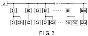
- FIG. 2 shows the piping connection state of the outdoor unit A, the cooling-heating switching units B1 to B10 and the indoor units C1 to C64 on the refrigeration cycle.
- Two indoor units (second indoor units) C1 and C64 are connected in parallel to the cooling-heating switching unit (second cooling-heating switching unit) B1 by piping, and one indoor unit (first indoor unit) C2 is connected to the cooling-heating switching unit (first cooling-heating switching unit) B2 by piping.
- One indoor unit (first indoor unit) C3 is connected to the cooling-heating switching unit (first cooling-heating switching unit) B3 by piping, and two indoor units (second indoor units) C4 and C21 are connected in parallel to the cooling-heating switching unit (second cooling-heating switching unit) B4 by piping. Further, two indoor units (second indoor units) C61 and C62 are connected to the cooling-heating switching unit (second cooling-heating switching unit) B9 by piping, and one indoor unit (first indoor unit) C63 is connected to the cooling-heating switching unit (first cooling-heating switching unit) B10 by piping.
- the cooling-heating switching unit B1 includes a liquid refrigerant channel L1 which guides a liquid refrigerant flowing out from the refrigeration unit 1 to the liquid pipe 11 to the indoor units C1 and C64 and also guides a liquid refrigerant flowing out from the indoor units C1 and C64 to the liquid pipe 11, a double pipe 31 in which one pipeline is arranged in the liquid refrigerant channel L1, a heating channel L2 which guides a gaseous refrigerant flowing from the refrigeration unit 1 to the discharge gas pipe 12 to the indoor units C1 and C64, an on-off valve (second valve) 32 which opens and closes the heating channel L2, a cooling channel L3 which guides a gaseous refrigerant flowing out from the indoor unit C1 to the suction gas pipe 13, an on-off valve (second valve) 33 which opens and closes the cooling channel L3, an subcooling circuit L4 which communicates between the liquid refrigerant channel L1 and the cooling channel L3 through the other pipeline of the double pipe 31, and a pulse motor valve (PMV)
- the on-off valves 32 and 33 are electromagnetic on-off valves and have the function of switching the refrigerant channel.
- the electric expansion valve 34 is a pulse motor valve (PWM) in which the degree of opening continuously changes from fully closed to fully opened in accordance with the number of input drive pulses, and has the function of controlling the degree of subcooling.
- the electric expansion valve 34 will be hereinafter referred to as the pulse motor valve 34.
- the actual parallel connection of the indoor units C1 and C64 to the cooling-heating switching unit B1 is implemented by connecting branch pipes to the liquid pipe 51 and the gas pipe 52 drawn from the cooling-heating switching unit B1 and connecting the indoor units C1 and C64 to these pipes.
- the parallel connection of the indoor units C4 and C21 in the cooling-heating switching unit B4 and the parallel connection of the indoor units C61 and C62 in the cooling-heating switching unit B9 are similarly implemented.
- the other cooling-heating switching units B2, B3 and B10 also have the same structure as that of the cooling-heating switching unit B1 except that the number of indoor units to be connected is one.
- the indoor unit C1 includes a flow control valve (PMV; first valve) 61 and an indoor heat exchanger 62, takes in a liquid refrigerant from the liquid pipe 51 of the cooling-heating switching unit B1 via the flow control valve 61 during cooling, flows the intake liquid refrigerant to the indoor heat exchanger 62, and sends a gaseous refrigerant evaporated in the indoor heat exchanger 62 to the gas pipe 52 of the cooling-heating switching unit B1.
- PMV flow control valve
- the gaseous refrigerant is taken in from the gas pipe 52 of the cooling-heating switching unit B1 and is flown into the indoor heat exchanger 62, and a liquid refrigerant condensed in the indoor heat exchanger 62 is sent out to the liquid pipe 51 of the cooling-heating switching unit B1.
- the flow control valve 61 controls the amount of the refrigerant flowing in from the cooling-heating switching unit B1.
- the other indoor units C2 to C64 also have the same structure as that of the indoor unit C1.
- FIG. 1 shows a state in which the indoor units C1, C63 and C64 execute cooling operations and the indoor unit C2 executes a heating operation.
- the on-off valves 32 are closed (which are filled in with solid black in the drawing) and the on-off valves 33 are opened (which are hollow in the drawing).
- the on-off valve 32 is opened (which is hollow in the drawing), and the on-off valve 33 is closed (which is filled in with solid black in the drawing).
- the outdoor unit A includes a controller 2
- the cooling-heating switching units B1 to B10 include controllers 30, and the indoor units C1 to C64 include controllers 60.
- Remote-control operation units 70 are provided in the indoor units C1 to C64, respectively, and signal lines 71 for communication are arranged between the operation units 70 and the controllers 60 of the indoor units C1 to C64, respectively.
- the operation unit 70 of the indoor unit C1 operates on a power voltage supplied from the indoor unit C1, and instructs an operation mode (a shutdown mode, a cooling operation mode and a heating operation mode) and an indoor set temperature to the controller 60 of the inner unit C1 through the signal line 71 for communication.
- the operation units 70 of the other indoor units C2 to C64 also have the same function.
- the signal line 71 is arranged as the first signal line for communication between the controller 30 of the cooling-heating switching unit B2 and the controller 60 of one indoor unit C2.
- a signal line 72 is arranged as the second signal line for communication between the controller 30 of the cooling-heating switching unit B1 and the controller 60 of one of the two indoor units C1 and C64, for example, the indoor unit C1. Therefore, between the indoor units C1 and C64 connected in parallel by piping, the controller 30 of the cooling-heating switching unit B1 can communicate with the controller 60 of the indoor unit C1 but cannot communicate with the controller 60 of the other indoor unit C64.
- signal lines 73 are sequentially arranged as the third signal lines for communication between the controller 2 of the outdoor unit A and the controllers 60 of the indoor units C1 to C64.
- the controller 60 of the indoor unit C1 receives an instruction to the indoor unit C1 from the outdoor unit A via the signal line 73 and controls the degree of opening of the flow control valve 61 according to the instruction, and also receives an instruction to the destination cooling-heating switching unit B1 from the outdoor unit A via the signal line 73 and transfers the instruction to the destination cooling-heating switching unit B1 via the signal line 72.
- the controller 60 of the indoor unit C64 receives an instruction from the outdoor unit A to the indoor unit C1 via the signal line 73, and controls the degree of opening of the flow control valve 61 according to the instruction.
- the controller 30 of the cooling-heating switching unit B1 controls the on-off valves 32 and 33 according to the instruction transferred from the controller 60 of the indoor unit C1. That is, when the controller 30 of the cooling-heating switching unit B1 receives an instruction for the cooling operation mode from the controller 60 of the indoor unit C1, the controller 30 of the cooling-heating switching unit B1 controls the opening and closing of the on-off valves 32 and 33 such that a refrigerant channel for the cooling operation shown in FIG. 1 will be formed for the indoor units C1 and C64.
- the controller 30 of the cooling-heating switching unit B1 when the controller 30 of the cooling-heating switching unit B1 receives an instruction for the heating operation mode from the controller 60 of the indoor unit C1, the controller 30 of the cooling-heating switching unit B1 controls the opening and closing of the on-off valves 32 and 33 such that a refrigerant channel for the heating operation will be formed for the indoor units C1 and C64. Still further, when the controller 30 of the cooling-heating switching unit B1 receives an instruction for the shutdown mode from the controller 60 of the indoor unit C1, the controller 30 of the cooling-heating switching unit B1 fully closes the on-off valves 32 and 33.
- the controller 60 of the indoor unit C2 receives an instruction to the indoor unit C2 from the outdoor unit A via the signal line 73 and controls the degree of opening of the flow control valve 61 according to the instruction, and also receives an instruction to the destination cooling-heating switching unit B2 from the outdoor unit A via the signal line 73 and transfers the instruction to the destination cooling-heating switching unit B2 via the signal line 71.
- the controller 30 of the cooling-heating switching unit B2 controls the on-off valves 32 and 33 according to the instruction transferred from the controller 60 of the indoor unit C2. That is, when the controller 30 of the cooling-heating switching unit B2 receives an instruction for the heating operation mode from the controller 60 of the indoor unit C2, the controller 30 of the cooling-heating switching unit B2 controls the opening and closing of the on-off valves 32 and 33 such that a refrigeration channel for the heat operation shown in FIG. 1 will be formed for the indoor unit C2. Further, when the controller 30 of the cooling-heating switching unit B2 receives an instruction for the shutdown mode from the controller 60 of the indoor unit C2, the controller 30 of the cooling-heating switching unit B2 fully closes the on-off valves 32 and 33.
- the controller 60 of the indoor unit C63 receives an instruction to the indoor unit C63 from the outdoor unit A via the signal line 73 and controls the degree of opening of the flow control valve 61 according to the instruction, and also receives an instruction to the destination cooling-heating switching unit B10 via the signal line 73 and transfers the instruction to the destination cold-heating switching unit B10 via the signal line 71.
- the controller 30 of the cooling-heating switching unit B10 controls the on-off valves 32 and 33 according to the instruction transferred from the controller 60 of the indoor unit C63. That is, when the controller 30 of the cooling-heating switching unit B10 receives an instruction for the cooling operation mode from the controller 60 of the indoor unit C63, the controller 30 of the cooling-heating switching unit B10 controls the opening and closing of the on-off valves 32 and 33 such that a refrigerant channel for the cooling operation shown in FIG. 1 will be formed for the indoor unit C63. Further, when the controller 30 of the cooling-heating switching unit B10 receives an instruction for the shutdown mode from the controller 60 of the indoor unit C63, the controller 30 of the cooling-heating switching unit B10 fully closes the on-off valves 32 and 33.
- the cooling operation and the heating operation can be performed for each of the cooling-heating switching units.
- the operation can be stopped for each of the indoor units.
- the controller 2 of the outdoor unit A includes a detection section 2a, a setting section 2b, a communication section 2c, a determination section 2d, a communication section 2e and a control section 2f as main functions.
- the detection section 2a detects the indoor units C1, C64, C4, C21, ... , C61 and C62 connected in combination (connected in parallel) to the cooling-heating switching units by initial communications with all the indoor units C1 to C64.
- the setting section 2b sets the communication ranks of all the indoor units C1 to C64 such that the connection ranks of the indoor units C1, C64, C4, C21, ... , C61 and C62 which are connected in combination and are detected by the detection section 2a will be consecutive in the destination cooling-heating switching units B1, B4, B9 ... of the indoor units C1, C64, C4, C21, ... , C61 and C62.
- the communication section 2c performs communications including inquiries to all the indoor units C1 to C64 and responses to the inquiries from the indoor units C1 to C64 sequentially with all the indoor units C1 to C64 according to the communication ranks set in the setting section 2b.
- the determination section 2d determines the operation modes of the indoor units C2, C3, ... , C63 connected alone and the refrigerant channels of the cooling-heating switching units (first cooling-heating switching units) B2, B3, ... , B10 connected to the indoor units C2, C3, ... , C63. Further, according to the mutual relationship of the responses from the indoor units C1, C64, C4, C21, ...
- the determination section 2d determines the operation modes of the indoor units C1, C64, C4, C21, ... , C61 and C62 connected in combination and the refrigerant channels of the cooling-heating switching units B1, B4, ... , B9 connected to the indoor units C1, C64, C4, C21, ... , C61 and C62.
- the communication section 2e sequentially performs communications including instructions for the contents determined in the determination section 2d with all the indoor units C1 to C64 according to the communication ranks set in the setting section 2b.
- the control section 2f controls the operation of the outdoor unit A according to the responses received in the communication section 2c.
- sequential communications between the outdoor unit A and the indoor units C1 to C64 are periodic polling communication which includes the above-described “inquiries”, “responses” and “instructions” respectively in the communications.
- Step S1 When the power is turned on (YES in Step S1), the controller 2 of the outdoor unit A, which is the master unit, performs initial communications with the indoor units C1 to C64, which are the slave units, in a predetermined communication order based on the addresses unique to the indoor units C1 to C64 (Step S2).
- the controller 2 acquires common unit setting codes for detecting the arrangement order of the connections of the indoor units C1 to C64 to the cooling-heating switching units B1 to B10, from the controllers 60 of the indoor units C1 to C64.
- the addresses unique to the indoor units C1 to C64 are preliminarily registered in the internal memory of the controller 2 in association with, for example, the device IDs which are the identification information of the indoor units C1 to C64.
- the common unit setting code is registered for each of the indoor units to be connected, for example, by the operation on the operation unit 70 by the worker who does the work.
- the common unit setting code is not registered.
- FIGS. 1 and 2 when the indoor units C1 and C64 are connected in combination to the cooling-heating switching unit B1, a common unit setting code "1" indicative of the first combination connection is registered in each of the controllers 60 of the indoor units C1 and C64.
- a common unit setting code "2" indicative of the second combination connection is registered in each of the controllers 60 of the indoor units C4 and C21.
- a common unit setting code "18" indicative of the eighteenth combination connection is registered in each of the controllers 60 of the indoor units C61 and C62.
- FIG. 4 shows the relationship between the common unit setting codes registered for the indoor units C1 to C64 and the communication ranks set to the indoor units C1 to C64 based on the common unit setting codes.
- the set communication order corresponds directly to the arrangement order of the connections of the indoor units C1 to C64 to the cooling-heating switching units B1 to B10.
- the controller 2 updates and stores the set communication ranks in the internal memory and executes periodic communications according to the communication ranks and control based on the periodic communications (Step S13). That is, as shown in FIG. 5 , the controller 2 periodically repeats polling communication to sequentially perform communications of inquiries to the indoor units C1 to C64 according to the set communication ranks and successively receive responses to the inquiries from the indoor units C1 to C64.
- the controller 2 determines the operation modes of the indoor units C1 to C64 and the refrigerant channels of the cooling-heating switching units B1 to B10 according to the received responses, and provides instructions for the determined contents to the indoor units C1 to C64 and the cooling-heating switching units B1 to B10 and thereby controls the flow control valves 61 of the indoor units C1 to C64 and the on-off valves 32 and 33 of the cooling-heating switching units B1 to B10.
- a time t1 required for one round of the polling communication from the start of the communication with the indoor unit C1 ranked first in the communication order until the completion of the communication with the indoor unit C63 ranked last in the communication order is, for example, about 10 seconds.
- the controller 2 repeats the polling communication every set time t2. In the communication with one indoor unit, the "inquiry”, the “response” and the “instruction" are included.
- the operation modes of the indoor units C1 to C63 and the refrigerant channels of the cooling-heating switching units B1 to B10 are determined according to the contents of the "responses" during the communications in the first round, and the control of the outdoor unit A itself such as the number of revolutions of the compressor, the opening and closing and the degree of opening of the valve, and the switching direction of the four-way valve are also determined and executed according to the contents of the "responses”.
- the "instructions" for the operation modes of the indoor units C1 to C63 and the refrigerant channels of the cooling-heating switching units B1 to B10 determined according to the contents of "responses" during the communications in the first round are included in the communications in the second round.
- the operation modes and the refrigerant channels are determined again according to the contents of the "responses" during the communications in the second round, and the "instructions" for the determined contents are included in the communications in the third round. Thereafter, similar processes will be repeated.
- the controller 2 can receive the response from the indoor unit C1 and the response from the indoor unit C64 at substantially the same time. At this time, the controller 2 does not respond each time the controller 2 receives responses respectively from the indoor units C1 and C64, but determines the operation mode and the refrigerant channel based on the mutual relationship of responses received respectively from the indoor units C1 and C64.
- the controller 2 then provides an instruction for controlling the flow control valves 61 of the indoor units C1 and C64 to the degree of opening corresponding to the determined operation mode, and an instruction for controlling the on-off valves 32 and 33 of the cooling-heating switching unit B1 to the opening-closing state corresponding to the determined refrigerant channel.
- the communications for these instructions are also successively performed without the interval of the time t1 required for one round of the polling communication.
- the operation state (shutdown, cooling operation and heating operation) set in the indoor units C1 and C64 and the refrigerant channel set in the destination cooling-heating switching unit B1 of the indoor units C1 and C64 can be matched with each other almost without any time delay.
- the flow control valves 61 of the indoor units C1 and C64 and the on-off valves 32, 33 of the cooling-heating switching unit B1 will not repeat operations frequently, and unpleasant sounds such as the sound of operations and the flow sound of refrigerants can be reduced. Further, it is possible to prevent instability of the refrigeration cycle control associated with delay in providing instructions to various valves provided in the cooling-heating switching unit B1 and the indoor units C1 and C64.
- the indoor units C1 and C64 are concurrently switched from the cooling operation to the heating operation, such a time lag that one indoor unit switches to the cooling operation, and after the time t1 required for one round of the polling communication, the other indoor unit switches from the heating operation to the cooling operation will not occur.
- Step S14 the controller 2 monitors the power shutdown (Step S14). If the power is not turned off (NO in Step S14), the controller 2 returns to Step S13 and repeats the periodic communications and the control based on the periodic communications. If the power is turned off (YES in Step S14), the controller 2 ends the processes.
- the embodiment has been described based on the assumption that a cooling-heating switching unit to which a plurality of indoor units are connected in combination and a cooling-heating switching unit to which an indoor unit is connected alone exist on the same refrigeration cycle.
- a plurality of indoor units are connected in combination to each of all the cooling-heating switching units, for example, two indoor units are connected to each of ten cooling-heating switching units in combination (twenty indoor units in total)
- the embodiment can be similarly implemented.
Landscapes
- Engineering & Computer Science (AREA)
- Mechanical Engineering (AREA)
- General Engineering & Computer Science (AREA)
- Physics & Mathematics (AREA)
- Thermal Sciences (AREA)
- Chemical & Material Sciences (AREA)
- Combustion & Propulsion (AREA)
- Air Conditioning Control Device (AREA)
Abstract
Description
- Embodiments described herein relate generally to an air conditioning apparatus in which a plurality of cooling-heating switching units are connected to one outdoor unit, one or more indoor units are connected to each of the cooling-heating switching units, and a shutdown, a cooling operation and a heating operation can be concurrently set in each of the indoor units.
- An air conditioning apparatus which can perform a shutdown, a cooling operation and a heating operation in each of the indoor units by connecting a plurality of cooling-heating switching units to one outdoor unit, connecting one indoor unit to each of the cooling-heating switching units, and switching a refrigerant channel between the outdoor unit and each of the indoor units by each of the cooling-heating switching units has been known. Further, a plurality of indoor units can be connected in parallel to one cooling-heating switching unit.
- Each of the indoor units includes, for example, a flow control valve which controls the flow amount of a refrigerant. Each of the cooling-heating switching units includes one or more on-off valves which switch a refrigerant channel. In the indoor units whose connection destinations are the same cooling-heating switching unit, the same operation mode is set on the condition that priority is given to the heating operation, and a refrigerant channel corresponding to this operation mode is set in the cooling-heating switching unit.
- In this air conditioning apparatus, the controller of an outdoor unit is set as a master unit (host) and the controllers of the indoor units are set as slave units (terminals or clients), and inquiries are sequentially made from the master unit to the slave units and responses to the inquiries are received from the slave units by the master unit, that is, so-called polling communication is periodically repeated. The master unit controls the operation of the master unit according to the responses from the slave units, controls the slave units (indoor units) according to the responses from the slave units, and also controls the refrigerant channels of the cooling-heating switching units connected to the indoor units via the indoor units. The order of communications from the master unit to the slave units is determined in advance based on the addresses unique to the slave units.
- Patent Literature 1:
JP 2008-39276 A - The unique addresses of the slave units (indoor units) are manually set by the contractor during the installation of the indoor units or are automatically assigned by the outdoor unit during the first trial operation after all the indoor units are installed. Therefore, the unique addresses of the indoor units are often set regardless of connections to the cooling-heating switching units.
- Therefore, two indoor units whose communication ranks are far from each other may be connected to one cooling-heating switching unit. In this case, a time difference is caused between the communication to the high-communication-rank indoor unit and the communication to the low-communication-rank indoor unit. If the time difference is large, the operations of the flow control valves in both indoor units and the operation of the on-off valve in the cooling-heating switching unit will be inappropriate. More specifically, the operation state (shutdown, cooling operation and heating operation) set in both indoor units and the refrigerant channel set in the destination cooling-heating switching unit of both indoor units will not match with each other. Further, in this case, the flow control valves of both indoor units and the on-off valve of the cooling-heating switching unit frequently repeat operations, and the sound of the operations or the flow sound of the refrigerant are frequently produced, and the user may feel uncomfortable.
- Embodiments described herein aim to provide an air conditioning apparatus which can match an operation state set in each of indoor units and a refrigerant channel set in each of cooling-heating switching units without time delay and can thereby realize an appropriate operation in each of indoor units and reduce an uncomfortable sound.
- An air conditioning apparatus according to
Claim 1 comprises an outdoor unit, a plurality of cooling-heating switching units connected to the outdoor unit, and a plurality of indoor units connected alone or in combination to the cooling-heating switching units, and can perform a cooling operation and a heating operation for each of the cooling-heating switching units by switching a channel of a refrigerant between the outdoor unit and each of the indoor units by each of the cooling-heating switching units. Each of the indoor units includes a first valve which controls an amount of the refrigerant flowing in from the cooling-heating switching unit which is a destination cooling-heating switching unit of the indoor unit, controls the first valve according to an instruction from the outdoor unit, and transfers the instruction from the outdoor unit to the destination cooling-heating switching unit. Each of the cooling-heating switching units includes a second valve which switches the channel of the refrigerant between the outdoor unit and each of the indoor units, and controls the second valve according to the instruction transferred from the indoor unit. The outdoor unit sets a communication rank to each of the indoor units such that the indoor units connected in combination are ranked consecutively, the outdoor unit sequentially performs a communication including an inquiry to each of the indoor units and a response to the inquiry from each of the indoor units, with each of the indoor units, the outdoor unit determines an operation mode of each of the indoor units and a refrigerant channel of each of the cooling-heating switching units according to the responses from all the indoor units, and the outdoor unit sequentially performs a communication including an instruction for a determined content, with each of the indoor units according to the set communication rank. -
-
FIG. 1 is a block diagram showing a structure according to an embodiment. -
FIG. 2 is a diagram showing a piping connection state of an outdoor unit, a plurality of cooling-heating switching units and a plurality of indoor units on a refrigeration cycle according to an embodiment. -
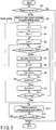
FIG. 3 is a flowchart showing control of the outdoor unit according to an embodiment. -
FIG. 4 is a diagram showing a method of setting a communication ranks according to an embodiment. -
FIG. 5 is a time chart showing polling communication according to an embodiment. - Embodiments of the present invention will be described hereinafter with reference to the accompanying drawings.
- As shown in
FIG. 1 , an outdoor unit A includes a refrigeration cycle unit 1 (hereinafter referred to as "a refrigeration unit") including a compressor, a four-way valve, an outdoor heat exchanger and the like. A liquid pipe 11, a discharge gas pipe 12 and asuction gas pipe 13 are drawn out from therefrigeration unit 1. The liquid pipe 11 guides a liquid refrigerant flowing out from the outdoor heat exchanger to each of the indoor units which will be described later in one case, and guides a liquid refrigerant flowing out from each of the indoor units to the outdoor heat exchanger in other case. The discharge gas pipe 12 guides a refrigerant discharged from the compressor to each of the indoor units. Thesuction gas pipe 13 guides a gaseous refrigerant flowing out from each of the indoor units to the suction side of the compressor. - A plurality of cooling-heating switching units B1 to B10 are connected to the liquid pipe 11, the discharge gas pipe 12 and the
suction gas pipe 13 via a plurality ofliquid pipes 21, a plurality ofgas pipes 22, and a plurality of gas pipes 23. For example, 64 indoor units C1 to C64 are connected to the cooling-heating switching units B1 to B10 vialiquid pipes 51 andgas pipes 52, respectively. Depending on the installation place of the air conditioning apparatus, etc., one indoor unit is connected alone to one cooling-heating switching unit in one case, and a plurality of indoor units are connected in parallel to one cooling-heating switching unit in the other case. Parallel connection is also referred to as combination connection. At the stage of use after installation, some indoor units may be added or replaced. Here, the cooling-heating switching unit to which one indoor unit is connected alone and the cooling-heating switching unit to which a plurality of indoor units are connected in parallel are the same as each other as the unit itself. Further, the number of indoor units which can be connected in parallel to one cooling-heating switching unit is determined by the relationship between the thickness of the refrigerant pipe in the destination cooling-heating switching unit and the total refrigeration capacity of the indoor units to be connected, and the upper limit is generally two. -
FIG. 2 shows the piping connection state of the outdoor unit A, the cooling-heating switching units B1 to B10 and the indoor units C1 to C64 on the refrigeration cycle. Two indoor units (second indoor units) C1 and C64 are connected in parallel to the cooling-heating switching unit (second cooling-heating switching unit) B1 by piping, and one indoor unit (first indoor unit) C2 is connected to the cooling-heating switching unit (first cooling-heating switching unit) B2 by piping. One indoor unit (first indoor unit) C3 is connected to the cooling-heating switching unit (first cooling-heating switching unit) B3 by piping, and two indoor units (second indoor units) C4 and C21 are connected in parallel to the cooling-heating switching unit (second cooling-heating switching unit) B4 by piping. Further, two indoor units (second indoor units) C61 and C62 are connected to the cooling-heating switching unit (second cooling-heating switching unit) B9 by piping, and one indoor unit (first indoor unit) C63 is connected to the cooling-heating switching unit (first cooling-heating switching unit) B10 by piping. - The cooling-heating switching unit B1 includes a liquid refrigerant channel L1 which guides a liquid refrigerant flowing out from the
refrigeration unit 1 to the liquid pipe 11 to the indoor units C1 and C64 and also guides a liquid refrigerant flowing out from the indoor units C1 and C64 to the liquid pipe 11, adouble pipe 31 in which one pipeline is arranged in the liquid refrigerant channel L1, a heating channel L2 which guides a gaseous refrigerant flowing from therefrigeration unit 1 to the discharge gas pipe 12 to the indoor units C1 and C64, an on-off valve (second valve) 32 which opens and closes the heating channel L2, a cooling channel L3 which guides a gaseous refrigerant flowing out from the indoor unit C1 to thesuction gas pipe 13, an on-off valve (second valve) 33 which opens and closes the cooling channel L3, an subcooling circuit L4 which communicates between the liquid refrigerant channel L1 and the cooling channel L3 through the other pipeline of thedouble pipe 31, and a pulse motor valve (PMV) 34 which controls the refrigerant flow amount of the subcooling circuit L4. The on-offvalves electric expansion valve 34 is a pulse motor valve (PWM) in which the degree of opening continuously changes from fully closed to fully opened in accordance with the number of input drive pulses, and has the function of controlling the degree of subcooling. Theelectric expansion valve 34 will be hereinafter referred to as thepulse motor valve 34. The actual parallel connection of the indoor units C1 and C64 to the cooling-heating switching unit B1 is implemented by connecting branch pipes to theliquid pipe 51 and thegas pipe 52 drawn from the cooling-heating switching unit B1 and connecting the indoor units C1 and C64 to these pipes. The parallel connection of the indoor units C4 and C21 in the cooling-heating switching unit B4 and the parallel connection of the indoor units C61 and C62 in the cooling-heating switching unit B9 are similarly implemented. - The other cooling-heating switching units B2, B3 and B10 also have the same structure as that of the cooling-heating switching unit B1 except that the number of indoor units to be connected is one.
- The indoor unit C1 includes a flow control valve (PMV; first valve) 61 and an
indoor heat exchanger 62, takes in a liquid refrigerant from theliquid pipe 51 of the cooling-heating switching unit B1 via theflow control valve 61 during cooling, flows the intake liquid refrigerant to theindoor heat exchanger 62, and sends a gaseous refrigerant evaporated in theindoor heat exchanger 62 to thegas pipe 52 of the cooling-heating switching unit B1. During heating, the gaseous refrigerant is taken in from thegas pipe 52 of the cooling-heating switching unit B1 and is flown into theindoor heat exchanger 62, and a liquid refrigerant condensed in theindoor heat exchanger 62 is sent out to theliquid pipe 51 of the cooling-heating switching unit B1. Theflow control valve 61 controls the amount of the refrigerant flowing in from the cooling-heating switching unit B1. The other indoor units C2 to C64 also have the same structure as that of the indoor unit C1. -
FIG. 1 shows a state in which the indoor units C1, C63 and C64 execute cooling operations and the indoor unit C2 executes a heating operation. In this case, in the cooling-heating switching units B1 and B10 connected to the indoor units C1, C63 and C64 in the cooling operation, the on-offvalves 32 are closed (which are filled in with solid black in the drawing) and the on-offvalves 33 are opened (which are hollow in the drawing). In the cooling-heating switching unit B2 connected to the indoor unit C2 in the heating operation, the on-offvalve 32 is opened (which is hollow in the drawing), and the on-offvalve 33 is closed (which is filled in with solid black in the drawing). - In the meantime, the outdoor unit A includes a
controller 2, the cooling-heating switching units B1 to B10 includecontrollers 30, and the indoor units C1 to C64 includecontrollers 60. Remote-control operation units 70 are provided in the indoor units C1 to C64, respectively, andsignal lines 71 for communication are arranged between theoperation units 70 and thecontrollers 60 of the indoor units C1 to C64, respectively. Theoperation unit 70 of the indoor unit C1 operates on a power voltage supplied from the indoor unit C1, and instructs an operation mode (a shutdown mode, a cooling operation mode and a heating operation mode) and an indoor set temperature to thecontroller 60 of the inner unit C1 through thesignal line 71 for communication. Theoperation units 70 of the other indoor units C2 to C64 also have the same function. - The
signal line 71 is arranged as the first signal line for communication between thecontroller 30 of the cooling-heating switching unit B2 and thecontroller 60 of one indoor unit C2. Asignal line 72 is arranged as the second signal line for communication between thecontroller 30 of the cooling-heating switching unit B1 and thecontroller 60 of one of the two indoor units C1 and C64, for example, the indoor unit C1. Therefore, between the indoor units C1 and C64 connected in parallel by piping, thecontroller 30 of the cooling-heating switching unit B1 can communicate with thecontroller 60 of the indoor unit C1 but cannot communicate with thecontroller 60 of the other indoor unit C64. Further,signal lines 73 are sequentially arranged as the third signal lines for communication between thecontroller 2 of the outdoor unit A and thecontrollers 60 of the indoor units C1 to C64. - The
controller 60 of the indoor unit C1 receives an instruction to the indoor unit C1 from the outdoor unit A via thesignal line 73 and controls the degree of opening of theflow control valve 61 according to the instruction, and also receives an instruction to the destination cooling-heating switching unit B1 from the outdoor unit A via thesignal line 73 and transfers the instruction to the destination cooling-heating switching unit B1 via thesignal line 72. Thecontroller 60 of the indoor unit C64 receives an instruction from the outdoor unit A to the indoor unit C1 via thesignal line 73, and controls the degree of opening of theflow control valve 61 according to the instruction. - The
controller 30 of the cooling-heating switching unit B1 controls the on-offvalves controller 60 of the indoor unit C1. That is, when thecontroller 30 of the cooling-heating switching unit B1 receives an instruction for the cooling operation mode from thecontroller 60 of the indoor unit C1, thecontroller 30 of the cooling-heating switching unit B1 controls the opening and closing of the on-offvalves FIG. 1 will be formed for the indoor units C1 and C64. Further, when thecontroller 30 of the cooling-heating switching unit B1 receives an instruction for the heating operation mode from thecontroller 60 of the indoor unit C1, thecontroller 30 of the cooling-heating switching unit B1 controls the opening and closing of the on-offvalves controller 30 of the cooling-heating switching unit B1 receives an instruction for the shutdown mode from thecontroller 60 of the indoor unit C1, thecontroller 30 of the cooling-heating switching unit B1 fully closes the on-offvalves - The
controller 60 of the indoor unit C2 receives an instruction to the indoor unit C2 from the outdoor unit A via thesignal line 73 and controls the degree of opening of theflow control valve 61 according to the instruction, and also receives an instruction to the destination cooling-heating switching unit B2 from the outdoor unit A via thesignal line 73 and transfers the instruction to the destination cooling-heating switching unit B2 via thesignal line 71. - The
controller 30 of the cooling-heating switching unit B2 controls the on-offvalves controller 60 of the indoor unit C2. That is, when thecontroller 30 of the cooling-heating switching unit B2 receives an instruction for the heating operation mode from thecontroller 60 of the indoor unit C2, thecontroller 30 of the cooling-heating switching unit B2 controls the opening and closing of the on-offvalves FIG. 1 will be formed for the indoor unit C2. Further, when thecontroller 30 of the cooling-heating switching unit B2 receives an instruction for the shutdown mode from thecontroller 60 of the indoor unit C2, thecontroller 30 of the cooling-heating switching unit B2 fully closes the on-offvalves - The
controller 60 of the indoor unit C63 receives an instruction to the indoor unit C63 from the outdoor unit A via thesignal line 73 and controls the degree of opening of theflow control valve 61 according to the instruction, and also receives an instruction to the destination cooling-heating switching unit B10 via thesignal line 73 and transfers the instruction to the destination cold-heating switching unit B10 via thesignal line 71. - The
controller 30 of the cooling-heating switching unit B10 controls the on-offvalves controller 60 of the indoor unit C63. That is, when thecontroller 30 of the cooling-heating switching unit B10 receives an instruction for the cooling operation mode from thecontroller 60 of the indoor unit C63, thecontroller 30 of the cooling-heating switching unit B10 controls the opening and closing of the on-offvalves FIG. 1 will be formed for the indoor unit C63. Further, when thecontroller 30 of the cooling-heating switching unit B10 receives an instruction for the shutdown mode from thecontroller 60 of the indoor unit C63, thecontroller 30 of the cooling-heating switching unit B10 fully closes the on-offvalves - The cooling operation and the heating operation can be performed for each of the cooling-heating switching units. The operation can be stopped for each of the indoor units.
- The
controller 2 of the outdoor unit A includes adetection section 2a, asetting section 2b, acommunication section 2c, adetermination section 2d, acommunication section 2e and acontrol section 2f as main functions. - When the outdoor unit A is powered on, the
detection section 2a detects the indoor units C1, C64, C4, C21, ... , C61 and C62 connected in combination (connected in parallel) to the cooling-heating switching units by initial communications with all the indoor units C1 to C64. Thesetting section 2b sets the communication ranks of all the indoor units C1 to C64 such that the connection ranks of the indoor units C1, C64, C4, C21, ... , C61 and C62 which are connected in combination and are detected by thedetection section 2a will be consecutive in the destination cooling-heating switching units B1, B4, B9 ... of the indoor units C1, C64, C4, C21, ... , C61 and C62. Thecommunication section 2c performs communications including inquiries to all the indoor units C1 to C64 and responses to the inquiries from the indoor units C1 to C64 sequentially with all the indoor units C1 to C64 according to the communication ranks set in thesetting section 2b. - Among the above-described responses received in the
communication section 2c, according to the responses from the indoor units except the indoor units C1, C64, C4, C21, ... , C61 and C62 connected in combination and detected by thedetection section 2a, that is, according to the responses from the indoor units C2, C3, ... , C63 connected alone, thedetermination section 2d determines the operation modes of the indoor units C2, C3, ... , C63 connected alone and the refrigerant channels of the cooling-heating switching units (first cooling-heating switching units) B2, B3, ... , B10 connected to the indoor units C2, C3, ... , C63. Further, according to the mutual relationship of the responses from the indoor units C1, C64, C4, C21, ... , C61 and C62 connected in combination and detected by thedetection section 2a, thedetermination section 2d determines the operation modes of the indoor units C1, C64, C4, C21, ... , C61 and C62 connected in combination and the refrigerant channels of the cooling-heating switching units B1, B4, ... , B9 connected to the indoor units C1, C64, C4, C21, ... , C61 and C62. Thecommunication section 2e sequentially performs communications including instructions for the contents determined in thedetermination section 2d with all the indoor units C1 to C64 according to the communication ranks set in thesetting section 2b. Thecontrol section 2f controls the operation of the outdoor unit A according to the responses received in thecommunication section 2c. - Note that the sequential communications between the outdoor unit A and the indoor units C1 to C64 are periodic polling communication which includes the above-described "inquiries", "responses" and "instructions" respectively in the communications.
- Next, the control executed by the
controller 2 of the outdoor unit A will be described with reference to the flowchart ofFIG. 3 . - When the power is turned on (YES in Step S1), the
controller 2 of the outdoor unit A, which is the master unit, performs initial communications with the indoor units C1 to C64, which are the slave units, in a predetermined communication order based on the addresses unique to the indoor units C1 to C64 (Step S2). In the initial communications, thecontroller 2 acquires common unit setting codes for detecting the arrangement order of the connections of the indoor units C1 to C64 to the cooling-heating switching units B1 to B10, from thecontrollers 60 of the indoor units C1 to C64. The addresses unique to the indoor units C1 to C64 are preliminarily registered in the internal memory of thecontroller 2 in association with, for example, the device IDs which are the identification information of the indoor units C1 to C64. - When a plurality of indoor units are connected to one cooling-heating switching unit, the common unit setting code is registered for each of the indoor units to be connected, for example, by the operation on the
operation unit 70 by the worker who does the work. When one indoor unit is connected alone to one cooling-heating switching unit, the common unit setting code is not registered. In the examples ofFIGS. 1 and2 , when the indoor units C1 and C64 are connected in combination to the cooling-heating switching unit B1, a common unit setting code "1" indicative of the first combination connection is registered in each of thecontrollers 60 of the indoor units C1 and C64. When the indoor units C4 and C21 are connected in combination to the cooling-heating switching unit B4, a common unit setting code "2" indicative of the second combination connection is registered in each of thecontrollers 60 of the indoor units C4 and C21. When the indoor units C61 and C62 are connected in combination to the cooling-heating switching unit B9, for example, a common unit setting code "18" indicative of the eighteenth combination connection is registered in each of thecontrollers 60 of the indoor units C61 and C62. - After the initial communications, the
controller 2 executes rank setting processes of Steps S3 to S12. That is, thecontroller 2 sets an initial value "1" to a rank number J (Step S3), sets an initial value "1" to a code number Xn (Step S4) and sets an initial value "1" as an indoor unit number Cn (Step S5). Thecontroller 2 then determines whether or not the common unit setting code "1" corresponding to the code number Xn (= "1") is registered for the indoor unit C1 whose indoor unit number Cn is "1" (Step S6). - Since the common unit setting code "1" is registered for the indoor unit C1 (YES in Step S6), the
controller 2 sets the communication rank of the indoor unit C1 to "1" corresponding to the rank number J (= "1") (Step S7). Along with this setting, thecontroller 2 increases the rank number J by "1" to "2" (Step S8) and increases the indoor unit number Cn by "1" to "2" (Step S9). Thecontroller 2 then determines whether or not the new indoor unit number Cn (= "2") has reached the maximum value Cns (= "64") (Step S10). - Since the indoor unit number Cn (= "2") has not reached the maximum value Cns (= "64") (NO in Step S10), the
controller 2 returns to Step S6 and determines whether or not the common unit setting code Xn (= "1") is registered for the indoor unit C2 whose indoor unit number Cn is "2". - Since the common unit setting code "1" is not registered for the indoor unit C2 (NO in Step S6), the
controller 2 increases the indoor unit number Cn by "1" to "3" without performing the processes of Steps S7 and S8 (Step S9). Thecontroller 2 then determines whether or not the new indoor unit number Cn (= "3") has reached the maximum value Cns (= "64") (Step S10). - Since the indoor unit number Cn (= "3") has not reached the maximum value Cns (= "64") (NO in Step S10), the
controller 2 returns to Step S6 and determines whether or not the common unit setting code Xn (= "1") is registered for the indoor unit C3 whose indoor unit number Cn is "3". - Since the common unit setting code "1" is not registered for the indoor unit C3 (NO in Step S6), the
controller 2 increases the indoor unit number Cn by "1" to "4" without performing the processes of Steps S7 and S8 (Step S9). Thecontroller 2 then determines whether or not the new indoor unit number Cn (= "4") has reached the maximum value Cns (= "64") (Step S10). - Since the indoor unit number Cn (= "4") has not reached the maximum value Cns (= "64") (NO in Step S10), the
controller 2 returns to Step S6 and determines whether or not the common unit setting code Xn (= "1") is registered for the indoor unit C4 whose indoor unit number Cn is "4". - Since the common unit setting code "1" is not registered for the indoor unit C4 (NO in Step S6), the
controller 2 increases the indoor unit number Cn by "1" to "5" without performing the processes of Steps S7 and S8 (Step S9). Thecontroller 2 then determines whether or not the new indoor unit number Cn (= "5") has reached the maximum value Cns (= "64") (Step S10). - When the indoor unit number Cn is repeatedly increased by "1" and the indoor unit number Cn reaches the maximum value Cns (= "64") (YES in Step S10), the
controller 2 increases the code number Xn by "1" to "2" (Step S11). Thecontroller 2 then determines whether or not the code number Xn (= "2") has exceeded the set value Xns (= "18") corresponding to the maximum value of the registered common unit setting code (for example, "18") (Step S12). - Since the new code number Xn (= "2") has not exceeded the set value Xns (= "18") (NO in Step S12), the
controller 2 returns to Step S5 and sets the initial value "1" to the indoor unit number Cn again. Thecontroller 2 then determines whether or not the common unit setting code "2" corresponding to the new code number Xn (= "2") is registered for the indoor unit C1 whose indoor unit number Cn is "1" (Step S6). - Since the common unit setting code "2" is not registered for the indoor unit C1 (NO in Step S6), the
controller 2 increases the indoor unit number Cn by "1" to "2" without performing the processes of Steps S7 and S8 (Step S9). Thecontroller 2 then determines whether or not the new indoor unit number Cn (= "2") has reached the maximum value Cns (= "64") (Step S10). - Since the indoor unit number Cn (= "2") has not reached the maximum value Cns (= "64") (NO in Step S10), the
controller 2 returns to Step S6 and determines whether or not the common unit setting code Xn (= "2") is registered for the indoor unit C2 whose indoor unit number Cn is "2". - Since the common unit setting code "2" is not registered for the indoor unit C2 (NO in Step S6), the
controller 2 increases the indoor unit number Cn by "1" to "3" without performing the processes of Steps S7 and S8 (Step S9). Thecontroller 2 then determines whether or not the new indoor unit number Cn (= "3") has reached the maximum value Cns (= "64") (Step S10). - Since the indoor unit number Cn (= "3") has not reached the maximum value Cns (= "64") (NO in Step S10), the
controller 2 returns to Step S6 and determines whether or not the common unit setting code Xn (= "2") is registered for the indoor unit C3 whose indoor unit number Cn is "3". - Since the common unit setting code "2" is not registered for the indoor unit C3 (NO in step S6), the
controller 2 increases the indoor unit number Cn by "1" to "4" without performing the processes of Steps S7 and S8 (Step S9). Thecontroller 2 then determines whether or not the new indoor unit number Cn (= "4") has reached the maximum value Cns (= "64") (Step S10). - Since the indoor unit number Cn (= "4") has not reached the maximum value Cns (= "64") (NO in Step S10), the
controller 2 returns to Step S6 and determines whether or not the common unit setting code Xn (= "2") is registered for the indoor unit C4 whose indoor unit number is "4". - Since the common unit setting code "2" is registered for the indoor unit C4 (YES in Step S6), the
controller 2 sets the communication rank of the indoor unit C4 to "2" corresponding to the rank number J (= "2") (Step S7). Along with this determination, thecontroller 2 increases the rank number J by "1" to "3" (Step S8) and increases the indoor unit number Cn by "1" to "5" (Step S9). Thecontroller 2 then determines whether or not the new indoor unit number Cn (= "5") has reached the maximum value Cns (= "64") (Step S10). - When these processes are repeated and the code number Xn (= "2") exceeds the set value Xns (= "18") corresponding to the maximum value of the common unit setting code (for example, "18") (YES in Step S12), the communication rank setting is completed.
-
FIG. 4 shows the relationship between the common unit setting codes registered for the indoor units C1 to C64 and the communication ranks set to the indoor units C1 to C64 based on the common unit setting codes. The set communication order corresponds directly to the arrangement order of the connections of the indoor units C1 to C64 to the cooling-heating switching units B1 to B10. - The
controller 2 updates and stores the set communication ranks in the internal memory and executes periodic communications according to the communication ranks and control based on the periodic communications (Step S13). That is, as shown inFIG. 5 , thecontroller 2 periodically repeats polling communication to sequentially perform communications of inquiries to the indoor units C1 to C64 according to the set communication ranks and successively receive responses to the inquiries from the indoor units C1 to C64. Thecontroller 2 then determines the operation modes of the indoor units C1 to C64 and the refrigerant channels of the cooling-heating switching units B1 to B10 according to the received responses, and provides instructions for the determined contents to the indoor units C1 to C64 and the cooling-heating switching units B1 to B10 and thereby controls theflow control valves 61 of the indoor units C1 to C64 and the on-offvalves - A time t1 required for one round of the polling communication from the start of the communication with the indoor unit C1 ranked first in the communication order until the completion of the communication with the indoor unit C63 ranked last in the communication order is, for example, about 10 seconds. The
controller 2 repeats the polling communication every set time t2. In the communication with one indoor unit, the "inquiry", the "response" and the "instruction" are included. The operation modes of the indoor units C1 to C63 and the refrigerant channels of the cooling-heating switching units B1 to B10 are determined according to the contents of the "responses" during the communications in the first round, and the control of the outdoor unit A itself such as the number of revolutions of the compressor, the opening and closing and the degree of opening of the valve, and the switching direction of the four-way valve are also determined and executed according to the contents of the "responses". The "instructions" for the operation modes of the indoor units C1 to C63 and the refrigerant channels of the cooling-heating switching units B1 to B10 determined according to the contents of "responses" during the communications in the first round are included in the communications in the second round. The operation modes and the refrigerant channels are determined again according to the contents of the "responses" during the communications in the second round, and the "instructions" for the determined contents are included in the communications in the third round. Thereafter, similar processes will be repeated. - Through the above operation, the communications with the indoor units C1 and C64 connected in combination to the cooling-heating switching unit B1 will be successively performed without the interval of the time t1 required for one round of the polling communication. Therefore, the
controller 2 can receive the response from the indoor unit C1 and the response from the indoor unit C64 at substantially the same time. At this time, thecontroller 2 does not respond each time thecontroller 2 receives responses respectively from the indoor units C1 and C64, but determines the operation mode and the refrigerant channel based on the mutual relationship of responses received respectively from the indoor units C1 and C64. Thecontroller 2 then provides an instruction for controlling theflow control valves 61 of the indoor units C1 and C64 to the degree of opening corresponding to the determined operation mode, and an instruction for controlling the on-offvalves - That is, the operation state (shutdown, cooling operation and heating operation) set in the indoor units C1 and C64 and the refrigerant channel set in the destination cooling-heating switching unit B1 of the indoor units C1 and C64 can be matched with each other almost without any time delay. As a result, the
flow control valves 61 of the indoor units C1 and C64 and the on-offvalves - Along with the periodic communications and the control based on the periodic communications, the
controller 2 monitors the power shutdown (Step S14). If the power is not turned off (NO in Step S14), thecontroller 2 returns to Step S13 and repeats the periodic communications and the control based on the periodic communications. If the power is turned off (YES in Step S14), thecontroller 2 ends the processes. - The embodiment has been described based on the assumption that the number of outdoor units A is 1, the number of cooling-heating switching units B is 10 and the number of indoor units C is 64. However, these numbers are in no way restrictive.
- Further, the embodiment has been described based on the assumption that a cooling-heating switching unit to which a plurality of indoor units are connected in combination and a cooling-heating switching unit to which an indoor unit is connected alone exist on the same refrigeration cycle. However, also when a plurality of indoor units are connected in combination to each of all the cooling-heating switching units, for example, two indoor units are connected to each of ten cooling-heating switching units in combination (twenty indoor units in total), the embodiment can be similarly implemented.
- While certain embodiments and modifications have been described, these embodiments have been presented by way of example only, and are not intended to limit the scope of the inventions. Indeed, the novel embodiments and modifications described herein may be embodied in a variety of other forms; furthermore, various omissions, substitutions and changes in the form of the embodiments and modifications described herein may be made without departing from the spirit of the inventions. The accompanying claims and their equivalents are intended to cover such forms or modifications as would fall within the scope and spirit of the inventions.
- A···outdoor unit, B1 to B10···cooling-heating switching units, C1 to C64···indoor units, 1···refrigeration unit, 2···controller, 11···liquid pipe, 12···discharge gas pipe, 13···suction gas pipe, L1···liquid refrigerant channel, L2···heating channel, L3···cooling channel, L4···subcooling circuit, 31···double pipe, 32···on-off valve (second valve), 33···on-off valve (second valve), 34···pulse motor valve, 30···controller, 61···flow control valve (first valve), 62···indoor heat exchanger, and 60···controller.
Claims (6)
- An air conditioning apparatus comprising an outdoor unit, a plurality of cooling-heating switching units connected to the outdoor unit, and a plurality of indoor units connected alone or in combination to the cooling-heating switching units, and configured to perform a cooling operation and a heating operation for each of the cooling-heating switching units by switching a channel of a refrigerant between the outdoor unit and each of the indoor units by each of the cooling-heating switching units, characterized in that
each of the indoor units includes a first valve which controls an amount of the refrigerant flowing in from the cooling-heating switching unit which is a destination cooling-heating switching unit of the indoor unit, controls the first valve according to an instruction from the outdoor unit, and transfers the instruction from the outdoor unit to the destination cooling-heating switching unit,
each of the cooling-heating switching units includes a second valve which switches the channel of the refrigerant between the outdoor unit and each of the indoor units, and controls the second valve according to the instruction transferred from the indoor unit,
the outdoor unit sets a communication rank to each of the indoor units such that the indoor units connected in combination are ranked consecutively,
the outdoor unit sequentially performs a communication including an inquiry to each of the indoor units and a response to the inquiry from each of the indoor units, with each of the indoor units,
the outdoor unit determines an operation mode of each of the indoor units and a refrigerant channel of each of the cooling-heating switching units according to the responses from all the indoor units, and
the outdoor unit sequentially performs a communication including an instruction for a determined content, with each of the indoor units according to the set communication rank. - The air conditioning apparatus of Claim 1, characterized in that
the outdoor unit detects the indoor units connected in combination by an initial communication with each of the indoor units, and
the outdoor unit sets the communication rank to each of the indoor units such that communications are successively performed with the detected indoor units. - The air conditioning apparatus of Claim 1, characterized in that
the first valve is a pulse motor valve whose degree of opening continuously changes from fully closed to fully opened, and
the second valve is a plurality of on-off valves. - The air conditioning apparatus of Claim 1, characterized in that the communication sequentially performed between the outdoor unit and each of the indoor units is periodic polling communication including the inquiry, the response and the instruction.
- The air conditioning apparatus of Claim 1, characterized in that the outdoor unit sequentially performs the communication including the inquiry to each of the indoor units and the response to the inquiry from each of the indoor units according to the set communication rank.
- The air conditioning apparatus of Claim 1, characterized in that each of the cooling-heating switching units is connected to one of the indoor units connected in combination by a signal line, and receives the instruction from the indoor unit connected via the signal line.
Applications Claiming Priority (1)
| Application Number | Priority Date | Filing Date | Title |
|---|---|---|---|
| PCT/JP2016/065796 WO2017203706A1 (en) | 2016-05-27 | 2016-05-27 | Air conditioner |
Publications (3)
| Publication Number | Publication Date |
|---|---|
| EP3467393A1 true EP3467393A1 (en) | 2019-04-10 |
| EP3467393A4 EP3467393A4 (en) | 2019-11-27 |
| EP3467393B1 EP3467393B1 (en) | 2021-09-15 |
Family
ID=60412735
Family Applications (1)
| Application Number | Title | Priority Date | Filing Date |
|---|---|---|---|
| EP16903187.9A Active EP3467393B1 (en) | 2016-05-27 | 2016-05-27 | Air conditioner |
Country Status (2)
| Country | Link |
|---|---|
| EP (1) | EP3467393B1 (en) |
| WO (1) | WO2017203706A1 (en) |
Family Cites Families (5)
| Publication number | Priority date | Publication date | Assignee | Title |
|---|---|---|---|---|
| JP4380738B2 (en) * | 2007-07-05 | 2009-12-09 | ダイキン工業株式会社 | Communication method between air conditioners, communication system between air conditioners, and communication program between air conditioners |
| JP5352512B2 (en) * | 2010-03-31 | 2013-11-27 | 日立アプライアンス株式会社 | Air conditioner |
| JP5316477B2 (en) * | 2010-05-17 | 2013-10-16 | ダイキン工業株式会社 | Air conditioning controller |
| JP2013181695A (en) * | 2012-03-01 | 2013-09-12 | Fujitsu General Ltd | Air conditioning device |
| JPWO2015111173A1 (en) * | 2014-01-23 | 2017-03-23 | 三菱電機株式会社 | Controller for air conditioner |
-
2016
- 2016-05-27 EP EP16903187.9A patent/EP3467393B1/en active Active
- 2016-05-27 WO PCT/JP2016/065796 patent/WO2017203706A1/en not_active Ceased
Also Published As
| Publication number | Publication date |
|---|---|
| EP3467393B1 (en) | 2021-09-15 |
| EP3467393A4 (en) | 2019-11-27 |
| WO2017203706A1 (en) | 2017-11-30 |
Similar Documents
| Publication | Publication Date | Title |
|---|---|---|
| CN104033995B (en) | Mode control method, mode control device and multi-connected air conditioner device | |
| EP3034966B1 (en) | Air-conditioning system | |
| US7819331B2 (en) | HVAC staging control | |
| KR101472019B1 (en) | Air conditioner and operating method thereof | |
| EP3279576A1 (en) | Variable refrigerant flow system | |
| CN113063212A (en) | Air conditioner and method and device for defrosting control of air conditioner | |
| EP4151921B1 (en) | Air conditioning apparatus | |
| KR101921537B1 (en) | Air-conditioner system | |
| JP2016118350A (en) | Air conditioner | |
| WO2016174750A1 (en) | Air-conditioning device | |
| US12410938B2 (en) | Damper control systems and methods for a zoning system | |
| JP2010032073A (en) | Air-conditioning system | |
| JPH11241869A (en) | Air conditioner | |
| EP3467393B1 (en) | Air conditioner | |
| EP3978817B1 (en) | Air-conditioning system | |
| CN105299848A (en) | Variable frequency air conditioner control device based on thermolator, terminal, system and method | |
| CN205245452U (en) | Variable frequency air conditioner controlling means , terminal and system based on thermoregulator | |
| US11965665B2 (en) | Air conditioning system | |
| KR20120033747A (en) | Air conditioner and method | |
| JP2001041534A (en) | Air conditioning system | |
| EP2916080B1 (en) | Air-conditioning apparatus | |
| CN205245453U (en) | Variable frequency air conditioner controlling means , terminal and system based on thermoregulator | |
| CN112781186B (en) | Air conditioner control method, air conditioner and readable storage medium | |
| KR20150091917A (en) | Air-conditioner and method | |
| JP7630016B1 (en) | Air conditioners |
Legal Events
| Date | Code | Title | Description |
|---|---|---|---|
| STAA | Information on the status of an ep patent application or granted ep patent |
Free format text: STATUS: THE INTERNATIONAL PUBLICATION HAS BEEN MADE |
|
| PUAI | Public reference made under article 153(3) epc to a published international application that has entered the european phase |
Free format text: ORIGINAL CODE: 0009012 |
|
| STAA | Information on the status of an ep patent application or granted ep patent |
Free format text: STATUS: REQUEST FOR EXAMINATION WAS MADE |
|
| 17P | Request for examination filed |
Effective date: 20181025 |
|
| AK | Designated contracting states |
Kind code of ref document: A1 Designated state(s): AL AT BE BG CH CY CZ DE DK EE ES FI FR GB GR HR HU IE IS IT LI LT LU LV MC MK MT NL NO PL PT RO RS SE SI SK SM TR |
|
| AX | Request for extension of the european patent |
Extension state: BA ME |
|
| DAV | Request for validation of the european patent (deleted) | ||
| DAX | Request for extension of the european patent (deleted) | ||
| REG | Reference to a national code |
Ref country code: DE Ref legal event code: R079 Ref document number: 602016063887 Country of ref document: DE Free format text: PREVIOUS MAIN CLASS: F24F0011020000 Ipc: F25B0013000000 |
|
| A4 | Supplementary search report drawn up and despatched |
Effective date: 20191025 |
|
| RIC1 | Information provided on ipc code assigned before grant |
Ipc: F24F 11/89 20180101ALI20191021BHEP Ipc: F25B 49/02 20060101ALI20191021BHEP Ipc: F25B 13/00 20060101AFI20191021BHEP |
|
| GRAP | Despatch of communication of intention to grant a patent |
Free format text: ORIGINAL CODE: EPIDOSNIGR1 |
|
| STAA | Information on the status of an ep patent application or granted ep patent |
Free format text: STATUS: GRANT OF PATENT IS INTENDED |
|
| INTG | Intention to grant announced |
Effective date: 20210409 |
|
| GRAS | Grant fee paid |
Free format text: ORIGINAL CODE: EPIDOSNIGR3 |
|
| GRAA | (expected) grant |
Free format text: ORIGINAL CODE: 0009210 |
|
| STAA | Information on the status of an ep patent application or granted ep patent |
Free format text: STATUS: THE PATENT HAS BEEN GRANTED |
|
| AK | Designated contracting states |
Kind code of ref document: B1 Designated state(s): AL AT BE BG CH CY CZ DE DK EE ES FI FR GB GR HR HU IE IS IT LI LT LU LV MC MK MT NL NO PL PT RO RS SE SI SK SM TR |
|
| REG | Reference to a national code |
Ref country code: CH Ref legal event code: EP |
|
| REG | Reference to a national code |
Ref country code: DE Ref legal event code: R096 Ref document number: 602016063887 Country of ref document: DE |
|
| REG | Reference to a national code |
Ref country code: IE Ref legal event code: FG4D |
|
| REG | Reference to a national code |
Ref country code: AT Ref legal event code: REF Ref document number: 1430804 Country of ref document: AT Kind code of ref document: T Effective date: 20211015 |
|
| REG | Reference to a national code |
Ref country code: NL Ref legal event code: FP |
|
| REG | Reference to a national code |
Ref country code: LT Ref legal event code: MG9D |
|
| PG25 | Lapsed in a contracting state [announced via postgrant information from national office to epo] |
Ref country code: SE Free format text: LAPSE BECAUSE OF FAILURE TO SUBMIT A TRANSLATION OF THE DESCRIPTION OR TO PAY THE FEE WITHIN THE PRESCRIBED TIME-LIMIT Effective date: 20210915 Ref country code: RS Free format text: LAPSE BECAUSE OF FAILURE TO SUBMIT A TRANSLATION OF THE DESCRIPTION OR TO PAY THE FEE WITHIN THE PRESCRIBED TIME-LIMIT Effective date: 20210915 Ref country code: BG Free format text: LAPSE BECAUSE OF FAILURE TO SUBMIT A TRANSLATION OF THE DESCRIPTION OR TO PAY THE FEE WITHIN THE PRESCRIBED TIME-LIMIT Effective date: 20211215 Ref country code: LT Free format text: LAPSE BECAUSE OF FAILURE TO SUBMIT A TRANSLATION OF THE DESCRIPTION OR TO PAY THE FEE WITHIN THE PRESCRIBED TIME-LIMIT Effective date: 20210915 Ref country code: NO Free format text: LAPSE BECAUSE OF FAILURE TO SUBMIT A TRANSLATION OF THE DESCRIPTION OR TO PAY THE FEE WITHIN THE PRESCRIBED TIME-LIMIT Effective date: 20211215 Ref country code: HR Free format text: LAPSE BECAUSE OF FAILURE TO SUBMIT A TRANSLATION OF THE DESCRIPTION OR TO PAY THE FEE WITHIN THE PRESCRIBED TIME-LIMIT Effective date: 20210915 Ref country code: FI Free format text: LAPSE BECAUSE OF FAILURE TO SUBMIT A TRANSLATION OF THE DESCRIPTION OR TO PAY THE FEE WITHIN THE PRESCRIBED TIME-LIMIT Effective date: 20210915 |
|
| REG | Reference to a national code |
Ref country code: AT Ref legal event code: MK05 Ref document number: 1430804 Country of ref document: AT Kind code of ref document: T Effective date: 20210915 |
|
| PG25 | Lapsed in a contracting state [announced via postgrant information from national office to epo] |
Ref country code: LV Free format text: LAPSE BECAUSE OF FAILURE TO SUBMIT A TRANSLATION OF THE DESCRIPTION OR TO PAY THE FEE WITHIN THE PRESCRIBED TIME-LIMIT Effective date: 20210915 Ref country code: GR Free format text: LAPSE BECAUSE OF FAILURE TO SUBMIT A TRANSLATION OF THE DESCRIPTION OR TO PAY THE FEE WITHIN THE PRESCRIBED TIME-LIMIT Effective date: 20211216 |
|
| PG25 | Lapsed in a contracting state [announced via postgrant information from national office to epo] |
Ref country code: AT Free format text: LAPSE BECAUSE OF FAILURE TO SUBMIT A TRANSLATION OF THE DESCRIPTION OR TO PAY THE FEE WITHIN THE PRESCRIBED TIME-LIMIT Effective date: 20210915 |
|
| PG25 | Lapsed in a contracting state [announced via postgrant information from national office to epo] |
Ref country code: IS Free format text: LAPSE BECAUSE OF FAILURE TO SUBMIT A TRANSLATION OF THE DESCRIPTION OR TO PAY THE FEE WITHIN THE PRESCRIBED TIME-LIMIT Effective date: 20220115 Ref country code: SM Free format text: LAPSE BECAUSE OF FAILURE TO SUBMIT A TRANSLATION OF THE DESCRIPTION OR TO PAY THE FEE WITHIN THE PRESCRIBED TIME-LIMIT Effective date: 20210915 Ref country code: SK Free format text: LAPSE BECAUSE OF FAILURE TO SUBMIT A TRANSLATION OF THE DESCRIPTION OR TO PAY THE FEE WITHIN THE PRESCRIBED TIME-LIMIT Effective date: 20210915 Ref country code: RO Free format text: LAPSE BECAUSE OF FAILURE TO SUBMIT A TRANSLATION OF THE DESCRIPTION OR TO PAY THE FEE WITHIN THE PRESCRIBED TIME-LIMIT Effective date: 20210915 Ref country code: PT Free format text: LAPSE BECAUSE OF FAILURE TO SUBMIT A TRANSLATION OF THE DESCRIPTION OR TO PAY THE FEE WITHIN THE PRESCRIBED TIME-LIMIT Effective date: 20220117 Ref country code: PL Free format text: LAPSE BECAUSE OF FAILURE TO SUBMIT A TRANSLATION OF THE DESCRIPTION OR TO PAY THE FEE WITHIN THE PRESCRIBED TIME-LIMIT Effective date: 20210915 Ref country code: ES Free format text: LAPSE BECAUSE OF FAILURE TO SUBMIT A TRANSLATION OF THE DESCRIPTION OR TO PAY THE FEE WITHIN THE PRESCRIBED TIME-LIMIT Effective date: 20210915 Ref country code: EE Free format text: LAPSE BECAUSE OF FAILURE TO SUBMIT A TRANSLATION OF THE DESCRIPTION OR TO PAY THE FEE WITHIN THE PRESCRIBED TIME-LIMIT Effective date: 20210915 Ref country code: CZ Free format text: LAPSE BECAUSE OF FAILURE TO SUBMIT A TRANSLATION OF THE DESCRIPTION OR TO PAY THE FEE WITHIN THE PRESCRIBED TIME-LIMIT Effective date: 20210915 Ref country code: AL Free format text: LAPSE BECAUSE OF FAILURE TO SUBMIT A TRANSLATION OF THE DESCRIPTION OR TO PAY THE FEE WITHIN THE PRESCRIBED TIME-LIMIT Effective date: 20210915 |
|
| REG | Reference to a national code |
Ref country code: DE Ref legal event code: R097 Ref document number: 602016063887 Country of ref document: DE |
|
| PLBE | No opposition filed within time limit |
Free format text: ORIGINAL CODE: 0009261 |
|
| STAA | Information on the status of an ep patent application or granted ep patent |
Free format text: STATUS: NO OPPOSITION FILED WITHIN TIME LIMIT |
|
| PG25 | Lapsed in a contracting state [announced via postgrant information from national office to epo] |
Ref country code: DK Free format text: LAPSE BECAUSE OF FAILURE TO SUBMIT A TRANSLATION OF THE DESCRIPTION OR TO PAY THE FEE WITHIN THE PRESCRIBED TIME-LIMIT Effective date: 20210915 |
|
| 26N | No opposition filed |
Effective date: 20220616 |
|
| PG25 | Lapsed in a contracting state [announced via postgrant information from national office to epo] |
Ref country code: SI Free format text: LAPSE BECAUSE OF FAILURE TO SUBMIT A TRANSLATION OF THE DESCRIPTION OR TO PAY THE FEE WITHIN THE PRESCRIBED TIME-LIMIT Effective date: 20210915 |
|
| REG | Reference to a national code |
Ref country code: DE Ref legal event code: R119 Ref document number: 602016063887 Country of ref document: DE |
|
| REG | Reference to a national code |
Ref country code: CH Ref legal event code: PL |
|
| REG | Reference to a national code |
Ref country code: BE Ref legal event code: MM Effective date: 20220531 |
|
| PG25 | Lapsed in a contracting state [announced via postgrant information from national office to epo] |
Ref country code: MC Free format text: LAPSE BECAUSE OF FAILURE TO SUBMIT A TRANSLATION OF THE DESCRIPTION OR TO PAY THE FEE WITHIN THE PRESCRIBED TIME-LIMIT Effective date: 20210915 Ref country code: LU Free format text: LAPSE BECAUSE OF NON-PAYMENT OF DUE FEES Effective date: 20220527 Ref country code: LI Free format text: LAPSE BECAUSE OF NON-PAYMENT OF DUE FEES Effective date: 20220531 Ref country code: IT Free format text: LAPSE BECAUSE OF FAILURE TO SUBMIT A TRANSLATION OF THE DESCRIPTION OR TO PAY THE FEE WITHIN THE PRESCRIBED TIME-LIMIT Effective date: 20210915 Ref country code: CH Free format text: LAPSE BECAUSE OF NON-PAYMENT OF DUE FEES Effective date: 20220531 |
|
| PG25 | Lapsed in a contracting state [announced via postgrant information from national office to epo] |
Ref country code: IE Free format text: LAPSE BECAUSE OF NON-PAYMENT OF DUE FEES Effective date: 20220527 |
|
| PG25 | Lapsed in a contracting state [announced via postgrant information from national office to epo] |
Ref country code: DE Free format text: LAPSE BECAUSE OF NON-PAYMENT OF DUE FEES Effective date: 20221201 Ref country code: BE Free format text: LAPSE BECAUSE OF NON-PAYMENT OF DUE FEES Effective date: 20220531 |
|
| PG25 | Lapsed in a contracting state [announced via postgrant information from national office to epo] |
Ref country code: HU Free format text: LAPSE BECAUSE OF FAILURE TO SUBMIT A TRANSLATION OF THE DESCRIPTION OR TO PAY THE FEE WITHIN THE PRESCRIBED TIME-LIMIT; INVALID AB INITIO Effective date: 20160527 |
|
| PG25 | Lapsed in a contracting state [announced via postgrant information from national office to epo] |
Ref country code: MK Free format text: LAPSE BECAUSE OF FAILURE TO SUBMIT A TRANSLATION OF THE DESCRIPTION OR TO PAY THE FEE WITHIN THE PRESCRIBED TIME-LIMIT Effective date: 20210915 Ref country code: CY Free format text: LAPSE BECAUSE OF FAILURE TO SUBMIT A TRANSLATION OF THE DESCRIPTION OR TO PAY THE FEE WITHIN THE PRESCRIBED TIME-LIMIT Effective date: 20210915 |
|
| PG25 | Lapsed in a contracting state [announced via postgrant information from national office to epo] |
Ref country code: MT Free format text: LAPSE BECAUSE OF FAILURE TO SUBMIT A TRANSLATION OF THE DESCRIPTION OR TO PAY THE FEE WITHIN THE PRESCRIBED TIME-LIMIT Effective date: 20210915 |
|
| PGFP | Annual fee paid to national office [announced via postgrant information from national office to epo] |
Ref country code: NL Payment date: 20250423 Year of fee payment: 10 |
|
| PGFP | Annual fee paid to national office [announced via postgrant information from national office to epo] |
Ref country code: GB Payment date: 20250423 Year of fee payment: 10 |
|
| PGFP | Annual fee paid to national office [announced via postgrant information from national office to epo] |
Ref country code: FR Payment date: 20250423 Year of fee payment: 10 |
|
| PG25 | Lapsed in a contracting state [announced via postgrant information from national office to epo] |
Ref country code: TR Free format text: LAPSE BECAUSE OF FAILURE TO SUBMIT A TRANSLATION OF THE DESCRIPTION OR TO PAY THE FEE WITHIN THE PRESCRIBED TIME-LIMIT Effective date: 20210915 |