EP3467344A1 - Speed reducer-attached motor - Google Patents
Speed reducer-attached motor Download PDFInfo
- Publication number
- EP3467344A1 EP3467344A1 EP18187062.7A EP18187062A EP3467344A1 EP 3467344 A1 EP3467344 A1 EP 3467344A1 EP 18187062 A EP18187062 A EP 18187062A EP 3467344 A1 EP3467344 A1 EP 3467344A1
- Authority
- EP
- European Patent Office
- Prior art keywords
- gear
- tooth
- internal tooth
- external tooth
- external
- Prior art date
- Legal status (The legal status is an assumption and is not a legal conclusion. Google has not performed a legal analysis and makes no representation as to the accuracy of the status listed.)
- Withdrawn
Links
Images




Classifications
-
- F—MECHANICAL ENGINEERING; LIGHTING; HEATING; WEAPONS; BLASTING
- F16—ENGINEERING ELEMENTS AND UNITS; GENERAL MEASURES FOR PRODUCING AND MAINTAINING EFFECTIVE FUNCTIONING OF MACHINES OR INSTALLATIONS; THERMAL INSULATION IN GENERAL
- F16H—GEARING
- F16H1/00—Toothed gearings for conveying rotary motion
- F16H1/28—Toothed gearings for conveying rotary motion with gears having orbital motion
- F16H1/32—Toothed gearings for conveying rotary motion with gears having orbital motion in which the central axis of the gearing lies inside the periphery of an orbital gear
- F16H2001/325—Toothed gearings for conveying rotary motion with gears having orbital motion in which the central axis of the gearing lies inside the periphery of an orbital gear comprising a carrier with pins guiding at least one orbital gear with circular holes
Definitions
- the present invention relates to a speed reducer-attached motor.
- a speed reducer-attached motor one such motor which includes a speed reduction mechanism that is operated by a hypocycloid speed reduction method (for example, refer to Japanese Unexamined Patent Application, First Publication No. 2016-93000 ).
- a speed reduction mechanism of a hypocycloid speed reduction method one such mechanism is known which includes an eccentric part that receives a rotation output of a motor part and is rotated, a swing gear that performs a swing movement (revolution movement) by the eccentric part and that has an internal tooth and an external tooth, a fixed gear that has a ring shape and that has an internal tooth which is engaged with an external tooth of an external tooth gear, and an output part that has an external tooth which is engaged with the internal tooth of the swing gear.
- the eccentric part has an eccentric outer circumferential surface of which the center is at an eccentric position with respect to a rotation axis line of the motor part, and the swing gear is inserted rotatably at the eccentric outer circumferential surface.
- the output part is rotated concentrically with the rotation axis line of the motor part.
- the swing gear when the eccentric part is rotated in accordance with the drive of the motor part, the swing gear performs a swing movement while being engaged with the fixed gear.
- the swing gear performs a rotation movement at a rotation number (rotation number of a rotation movement) having a more decreased speed (engagement first stage) than that of the rotation number of a revolution movement according to the engagement with the fixed gear.
- the rotation movement having a decreased speed of the swing gear is transmitted to the output part, and the output part is rotated at a rotation number having a more increased speed (engagement second stage) than that of the rotation number of the swing gear.
- an aspect of the present invention provides a high-efficiency and compact speed reducer-attached motor capable of adjusting a load balance at the time of driving without providing a balance weight.
- a speed reducer-attached motor includes: a motor part; and a speed reduction mechanism that reduces a speed of a rotation of the motor part and that outputs a rotation having a reduced speed
- the speed reduction mechanism includes: a gear casing; a first eccentric part of which a center is at an eccentric position with respect to a rotation axis line of the motor part and which is rotated in response to the rotation of the motor part; a second eccentric part of which a center is at a position that is displaced by 180° around the rotation axis line from the center of the first eccentric part and which is rotated integrally with the first eccentric part in response to the rotation of the motor part; a first swing gear that is fitted rotatably to the first eccentric part and that has a first external tooth and a first internal tooth; a second swing gear that is fitted rotatably to the second eccentric part and that has a second external tooth and a second internal tooth; a fixed gear that is fixed to the gear casing and that has a
- each of the swing gears (first swing gear, second swing gear) is rotatably fitted to each of the first eccentric part and the second eccentric part.
- the first swing gear and the second swing gear are moved point-symmetrically around the rotation axis line, and therefore, it is possible to balance out the engagement reaction force between the first external tooth and the third internal tooth and the engagement reaction force between the second external tooth and the third internal tooth. Further, it is possible to balance out the engagement reaction force between the first internal tooth and the third external tooth and the engagement reaction force between the second internal tooth and the third external tooth. Accordingly, it is possible to adjust a load balance at the time of driving without providing a balance weight as in the related art, and it is possible to provide a high-efficiency speed reducer-attached motor.
- the tooth numbers of the first internal tooth, the second internal tooth, and the third external tooth are set to be smaller than the tooth numbers of the first external tooth, the second external tooth, and the third internal tooth, it is possible to ensure a space between teeth of the first internal tooth, the second internal tooth, and the third external tooth. By using this space, it is possible to engage the first internal tooth with the third external tooth, and it is possible to engage the second internal tooth with the third external tooth. Therefore, it is possible to downsize the speed reducer-attached motor.
- the first swing gear may have a first gear main body that is rotatably fitted to the first eccentric part and that has a circular plate shape, the first external tooth and the first internal tooth being provided on the first gear main body
- the second swing gear may have a second gear main body that is rotatably fitted to the second eccentric part and that has a circular plate shape, the second external tooth and the second internal tooth being provided on the second gear main body
- the first swing gear and the second swing gear may be arranged such that the first gear main body and the second gear main body are overlapped with each other in the rotation axis line direction, and a penetration hole through which the third external tooth of the output gear is capable of being inserted may be formed on each of the first gear main body and the second gear main body.
- the first swing gear, the second swing gear, the fixed gear, and the output gear in a small space.
- the space is small, it is possible to engage the first internal tooth with the third external tooth, and it is possible to engage the second internal tooth with the third external tooth.
- the tooth numbers of the first internal tooth, the second internal tooth, and the third external tooth may be set to be the same as one another.
- the first internal tooth, the second internal tooth, and the third external tooth it is possible to form the first internal tooth, the second internal tooth, and the third external tooth to be as large as possible. Therefore, it is possible to enhance strengths of the first internal tooth, the second internal tooth, and the third external tooth as much as possible.
- the third external tooth may have a cycloidal tooth profile.
- each of the swing gears (first swing gear, second swing gear) is rotatably fitted to each of the first eccentric part and the second eccentric part.
- the first swing gear and the second swing gear are moved point-symmetrically around the rotation axis line, and therefore, it is possible to balance out the engagement reaction force between the first external tooth and the third internal tooth and the engagement reaction force between the second external tooth and the third internal tooth.
- the tooth numbers of the first internal tooth, the second internal tooth, and the third external tooth are set to be smaller than the tooth numbers of the first external tooth, the second external tooth, and the third internal tooth, it is possible to ensure a space between teeth of the first internal tooth, the second internal tooth, and the third external tooth. By using this space, it is possible to engage the first internal tooth and the third external tooth with each other, and it is possible to engage the second internal tooth and the third external tooth with each other. Therefore, it is possible to downsize the speed reducer-attached motor.
- FIG. 1 is a perspective view of a speed reducer-attached motor 1.
- the speed reducer-attached motor 1 includes a motor part 2 having an oblate shape and a speed reduction mechanism 3 to which a rotation output of the motor part 2 is transmitted.
- a motor shaft line (rotation axis line) L1 which is a rotation center of the motor part 2 is matched with a rotation center (axis line) of an output shaft 51 of an output part 15 described later that constitutes the speed reduction mechanism 3.
- a side from which an output is taken out from the output shaft 51 is referred to as an upper side (upper side in FIG. 1 ), and the other side is referred to as a lower side (lower side in FIG. 1 ). That is, the motor part 2 is arranged on the lower side, and the speed reduction mechanism 3 is arranged on the upper side.
- a direction along the motor shaft line L1 is simply referred to as an axial direction.
- a direction around the motor shaft line L1 is simply referred to as a circumferential direction.
- a direction orthogonal to the motor shaft line L1 is referred to as a radial direction.
- the motor part 2 is constituted of a so-called DC brushless motor.
- the motor part 2 has a motor casing 4 having a substantially cylinder shape.
- a cover 6 is provided on a lower end of the motor casing 4 so as to close an opening of the motor casing 4.
- a plurality of bolt seats 7 are formed on a substantially upper half of an outer circumferential surface of the motor casing 4 such that the plurality of bolt seats 7 protrude toward a radially outward direction.
- Each bolt seat 7 is used for fastening and fixing the motor casing 4 and a gear casing 10 described later to each other by a bolt (not shown).
- a female screw part (not shown) is engraved on each bolt seat 7.
- the bolt seats 7 are arranged at a substantially equal interval in a circumferential direction.
- a stator (not shown) is fixed to an inner circumferential surface of the motor casing 4.
- a rotor (not shown) is provided rotatably with respect to the stator on an inner side in the radial direction of the stator.
- a coil (not shown) is wound around the stator.
- the coil is formed to be electrically connectable to an external electric source (not shown) via an electric source window 5a that is formed as an opening on a circumferential wall 5 of the motor casing 4.
- an electric source window 5a that is formed as an opening on a circumferential wall 5 of the motor casing 4.
- FIG. 2 is a cross-sectional view along an axial direction of the speed reduction mechanism 3.
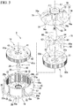
- FIG. 3 is an exploded perspective view of the speed reduction mechanism 3.
- the speed reduction mechanism 3 is formed as a so-called hypocycloid speed reduction mechanism.
- the speed reduction mechanism 3 includes the gear casing 10 that is arranged on the motor casing 4, an eccentric shaft 11 that is rotatably supported by the gear casing 10, a ring gear 12 (fixed gear) that is fixed inside the gear casing 10, a first swing gear 13 and a second swing gear 14 that are engaged with the ring gear 12, and the output part 15 that is engaged with the first swing gear 13.
- the gear casing 10 is formed in a substantially tube shape having a bottom.
- the gear casing 10 is arranged such that a bottom wall 16 of the gear casing 10 is directed to the motor part 2 side (lower side). That is, the bottom wall 16 of the gear casing 10 has a role of closing an opening at an upper end of the motor casing 4 and partitioning the motor part 2 and the speed reduction mechanism 3.
- the outer diameter of the outer circumferential surface of a circumferential wall 17 in the gear casing 10 is set to be slightly smaller than the outer diameter of the outer circumferential surface in the motor casing 4.
- a plurality of bolt seats 18 that extend in the axial direction are integrally molded on the outer circumferential surface of the circumferential wall 17.
- the bolt seats 18 are used for fastening and fixing a cover 70 described later to the gear casing 10 by a bolt (not shown).
- the bolt seats 18 are formed throughout the entire region in the axial direction of the circumferential wall 17 and are arranged at an equal interval in the circumferential direction.
- a female screw part 18a is engraved along the axial direction on each bolt seat 18.
- An outer flange part 19 is formed on an end portion on the motor casing 4 side of the circumferential wall 17.
- the outer diameter of the outer flange part 19 is set to be substantially the same as the outer diameter of the outer circumferential surface in the motor casing 4.
- a bolt seat 20 is formed on the outer flange part 19 at each of positions that correspond to the bolt seats 7 of the motor casing 4 such that the bolt seat 20 protrudes toward a radially outward direction.
- the bolt seats 7 and 20 are overlapped with each other in the axial direction.
- a bolt insertion hole 20a is formed on each bolt seat 20 of the gear casing 10.
- a bolt (not shown) is threaded into the female screw part (not shown) that is engraved on the bolt seat 7 of the motor casing 4 via the bolt insertion hole 20a. Thereby, the motor casing 4 and the gear casing 10 are fastened and fixed to each other.
- a bearing housing 21 is integrally molded on the center in the radial direction of the bottom wall 16 of the gear casing 10.
- the bearing housing 21 is formed in a substantially oval shape when seen from the axial direction.
- a bearing 22 is provided on the bearing housing 21 at the center in the radial direction of the bottom wall 16. The bearing 22 rotatably supports a lower part of the eccentric shaft 11 described later.
- the ring gear 12 is internally fitted and fixed to an inner circumferential surface of the circumferential wall 17 of the gear casing 10.
- the ring gear 12 is formed in a substantially tube shape having a bottom so as to correspond to the inner surface of the gear casing 10. That is, the ring gear 12 is formed so as to almost cover the inner surface of the circumferential wall 17 and the inner surface of the bottom wall 16 in the gear casing 10.
- An internal tooth 27a (third internal tooth) is formed on the entire inner circumferential surface of a circumferential wall 27 of the ring gear 12.
- a fit protrusion part 28a is formed entirely on a bottom wall 28 of the ring gear 12 via a predetermined gap from the internal tooth 27a such that the fit protrusion part 28a protrudes upward.
- the fit protrusion part 28a is formed on most of the center part in the radial direction of the bottom wall 28 of the ring gear 12 such that the fit protrusion part 28a protrudes upward.
- the fit protrusion part 28a is formed in a substantially circular shape when seen from the axial direction.
- the fit protrusion part 28a is used for regulating the displacement in the radial direction of the second swing gear 14 (details are described later).
- a fit hole 28a that has a substantially oval shape and that is capable of fitting to the bearing housing 21 of the gear casing 10 is formed on the bottom wall 28 of the ring gear 12.
- the fit hole 28a of the ring gear 12 is fitted to the bearing housing 21 of the gear casing 10, and thereby, it is regulated that the ring gear 12 is rotated around the motor shaft line L1.
- the eccentric shaft 11 that is supported by the bearing 22 of the gear casing 10 has a shaft main body 23 that is concentric with the motor shaft line L1. A lower end of the shaft main body 23 is rotatably supported by the bearing 22. A connection shaft 24 that protrudes toward the motor part 2 side is integrally molded on the lower end of the shaft main body 23 via the bearing 22. The connection shaft 24 is connected to the rotor (not shown) of the motor part 2 via a joint (not shown). Thereby, the rotation of the rotor is transmitted to the eccentric shaft 11.
- Two eccentric parts 25, 26, namely a first eccentric part 25 and a second eccentric part 26, are integrally molded on the center in the axial direction of the shaft main body 23.
- Each of the two eccentric parts 25, 26 is formed in a cylinder shape.
- the first eccentric part 25 is arranged on an upper side.
- the second eccentric part 26 is arranged on a lower side.
- An outer circumferential surface 25a of the first eccentric part 25 is formed of a cylindrical surface having a center 01 at an eccentric position with respect to the motor shaft line L1.
- An outer circumferential surface 26a of the second eccentric part 26 is formed of a cylindrical surface having a center O2 at an eccentric position with respect to the motor shaft line L1.
- An eccentric amount of the center 01 of the first eccentric part 25 is set to be the same as an eccentric amount of the center O2 of the second eccentric part 26.
- the first eccentric part 25 and the second eccentric part 26 are arranged such that the centers 01, O2 are displaced by 180° around the motor shaft line L1 from each other. That is, the center 01 of the first eccentric part 25 and the center O2 of the second eccentric part 26 are at point-symmetric positions around the motor shaft line L1.
- the first swing gear 13 is rotatably supported by the first eccentric part 25 via a bearing 29.
- the first swing gear 13 has a first gear main body 31 having a substantially circular plate shape.
- the first swing gear 13 is arranged on an inner side in the radial direction of the circumferential wall 27 of the ring gear 12.
- a bearing accommodation hole 31a to which an outer circumferential surface of the bearing 29 is fitted is formed on the center in the radial direction of the first gear main body 31.
- An external internal tooth ring 33 is provided on an outer circumferential part of the first gear main body 31 to stand toward an upward direction.
- An external tooth 33a (first external tooth) that is engaged with the internal tooth 27a of the ring gear 12 is formed on an outer circumferential surface of the external internal tooth ring 33.
- An internal tooth 33b (first internal tooth) is formed on an inner circumferential surface of the external internal tooth ring 33.
- the tooth number of the internal tooth 33b is set to be smaller than the tooth number of the external tooth 33a and the tooth number of the internal tooth 27a of the ring gear 12. Specifically, for example, the tooth number of the internal tooth 27a of the ring gear 12 is set to 43, and the tooth number of the external tooth 33a of the first swing gear 13 is set to 42. On the other hand, the tooth number of the internal tooth 33b of the first swing gear 13 is set to 9. Therefore, the circle pitch of the internal tooth 33b is greater than that of the external tooth 33a.
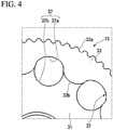
- FIG. 4 is a partially enlarged plan view seen from an axial direction of the first swing gear 13.
- a penetration hole 32 that penetrates in a thickness direction is formed between teeth of the internal tooth 33b on the first gear main body 31 of the first swing gear 13.
- a tooth shape arcing part 32a that is formed along the shape of the tooth bottom between teeth of the internal tooth 33b.
- an arc part 32b that continues smoothly to the tooth shape arcing part 32a.
- the tooth shape arcing part 32a has a cycloidal tooth profile.
- FIG. 5 is a perspective view of the second swing gear 14.
- the second swing gear 14 is rotatably supported by the second eccentric part 26 of the eccentric shaft 11 via a bearing 40.
- the second swing gear 14 has a second gear main body 41 having a substantially circular plate shape.
- the second swing gear 14 is arranged on an inner side in the radial direction of the circumferential wall 27 of the ring gear 12 and on a lower surface side of the first gear main body 31.
- a bearing accommodation hole 41a to which an outer circumferential surface of the bearing 40 is fitted is formed on the center in the radial direction of the second gear main body 41.
- a fit recess part 41b is formed on most of the center part in the radial direction of a lower surface of the second gear main body 41.
- the fit recess part 41b is loosely fitted to the fit protrusion part 28a that is formed on the bottom wall 28 of the ring gear 12. Thereby, a displacement in the radial direction of the second swing gear 14 is regulated.
- An external tooth 41c (second external tooth) that is engaged with the internal tooth 27a of the ring gear 12 is formed on an outer circumferential part of the second gear main body 41.
- the tooth number of the external tooth 41c is set to be the same as the tooth number of the external tooth 33a of the first swing gear 13.
- a penetration hole 42 (second internal tooth) is formed on the second gear main body 41 at a position that corresponds to the penetration hole 32 of the first swing gear 13 and at a position from an upper surface of the second gear main body 41 to the fit recess part 41b.
- the penetration hole 42 is formed in the same shape as that of the penetration hole 32 of the first swing gear 13. That is, half on an outer side in the radial direction of an inner circumferential edge of the penetration hole 42 is a tooth shape arcing part 42a (second internal tooth), and the other half on an inner side in the radial direction of the inner circumferential edge of the penetration hole 42 is an arc part 42b that continues smoothly to the tooth shape arcing part 42a.
- the tooth shape arcing part 42a has a cycloidal tooth profile.
- an outermost position at which the penetration hole 42 is formed is arranged at a slightly more outside position in the radial direction than the fit recess part 41b. Therefore, when seeing the second swing gear 14 from an upper side (the first swing gear 13 side), the circumferential edge of the fit recess part 41b becomes a state of being partially exposed via the penetration hole 42.
- FIG. 6 is a plan view seen from an axial direction of a state in which the eccentric shaft 11, the ring gear 12, the first swing gear 13, and the second swing gear 14 are stored inside the gear casing 10.
- the first swing gear 13 is rotatably supported by the first eccentric part 25 of the eccentric shaft 11 via the bearing 29, and the second swing gear 14 is rotatably supported by the second eccentric part 26 via the bearing 40. Therefore, as shown in FIG. 6 , the penetration hole 32 of the first swing gear 13 and the penetration hole 42 of the second swing gear 14 are formed at a position that corresponds to each other, but the positions of the penetration holes 32, 42 are not matched with each other when seen from the axial direction. That is, the penetration hole 32 of the first swing gear 13 and the penetration hole 42 of the second swing gear 14 are displaced by 180° around the motor shaft line L1.
- FIG. 7 is a perspective view of the output part 15.
- the output part 15 is arranged on the first swing gear 13 and on an inner side in the radial direction of the external internal tooth ring 33 of the first swing gear 13.
- the output part 15 is formed of the output shaft 51 that is formed in a substantially cylinder shape which is concentric with the motor shaft line L1 and an output gear 52 that is provided on a lower end of the output shaft 51.
- the output gear 52 is arranged on the first swing gear 13 and the inner side in the radial direction of the external internal tooth ring 33 of the first swing gear 13.
- connection shaft 53 to which a two-direction removal processing is applied is integrally molded on a front end of the output shaft 51 concentrically with the output shaft 51.
- a female screw part 53a is engraved on the connection shaft 53.
- the connection shaft 53 is used for outputting an output of the speed reducer-attached motor 1 to an external apparatus (now shown) by being connected to the external apparatus (not shown).
- a flange part 54 having a substantially circular plate shape is integrally molded on a lower end of the output shaft 51.
- a bearing housing 55 is formed on a lower surface of the flange part 54 such that the bearing housing 55 protrudes downward.
- a bearing 56 is internally fitted and fixed to the bearing housing 55.
- An upper end part of the eccentric shaft 11 is rotatably supported by the bearing 56.
- a bolt insertion hole 58 through which a bolt 57 is capable of being inserted is formed on an outer circumferential portion of the flange part 54.
- a counter boring portion 58a that receives a head part 57a of the bolt 57 is formed on an upper surface of the bolt insertion hole 58.
- the output gear 52 has a gear main body 60 having a substantially circular plate shape.
- a storage recess part 61 is formed on most of the center part in the radial direction of an upper surface of the gear main body 60.
- the diameter of the storage recess part 61 is set to be slightly larger than the diameter of the flange part 54.
- the flange part 54 of the output shaft 51 is stored in such a storage recess part 61.
- a female screw part 61a is engraved on the storage recess part 61 at a position that corresponds to the bolt insertion hole 58 of the flange part 54.
- a bolt 57 that is inserted into the bolt insertion hole 58 is threaded into the female screw part 61a.
- An external tooth 60a (third external tooth) that is concentric with the motor shaft line L1 is formed on an outer circumferential part of the gear main body 60.
- the external tooth 60a has a cycloidal tooth profile.
- the external tooth 60a is engaged with the internal tooth 33b of the first swing gear 13.
- the external tooth 60a has a protrusion part 62 that is formed to protrude along the axial direction and toward a downward direction.
- the protrusion part 62 is inserted in the penetration hole 32 of the first swing gear 13 and is further inserted in the penetration hole 42 of the second swing gear 14.
- a surface that continues to the external tooth 60a of the protrusion part 62 is a tooth shape arcing surface 62a (third external tooth) having a cycloidal tooth profile similarly to the external tooth 60a.
- a surface on an inner side in the radial direction other than the tooth shape arcing surface 62a of the protrusion part 62 is an arc surface 62b that smoothly continues to the tooth shape arcing surface 62a.
- the cover 70 is attached to an upper end of the gear casing 10 in a state where the eccentric shaft 11, the ring gear 12, the first swing gear 13, the second swing gear 14, and the flange part 54 of the output part 15 are stored inside the gear casing 10.
- the cover 70 is formed of a cover main body 71 that is formed in a substantially circular plate shape so as to close an opening of the circumferential wall 17 of the gear casing 10 and a bearing housing 72 that is formed to protrude upward from the cover main body 71.
- a spigot-and-socket fit part 73 that has an annular shape and that is fitted by spigot-and-socket fitting to the circumferential wall 17 of the gear casing 10 is formed to protrude on a lower surface of the cover main body 71. Positioning in the radial direction of the cover 70 with respect to the gear casing 10 is performed by the spigot-and-socket fit part 73. A front end of the spigot-and-socket fit part 73 is in contact with an upper end of the circumferential wall 27 of the ring gear 12.
- a bolt seat 74 is formed on an outer circumferential edge of the cover main body 71 at each of positions that correspond to the bolt seats 18 of the gear casing 10 such that the bolt seat 74 protrudes outward in the radial direction.
- a bolt insertion hole 74a that communicates with the female screw part 18a (refer to FIG. 3 ) of the gear casing 10 is formed on each bolt seat 74.
- a bolt (not shown) is threaded into the female screw part 18a of the gear casing 10 via the bolt insertion hole 74a. Thereby, the gear casing 10 and the cover 70 are fastened and fixed to each other.
- the bearing housing 72 is formed in a substantially cylinder shape and is arranged concentrically with the motor shaft line L1. An upper end of the output shaft 51 protrudes upward in the axial direction of the cover 70 via the bearing housing 72.
- Each of bearings 75a, 75b is provided on each of ends in the vertical direction of the bearing housing 72.
- the output shaft 51 is rotatably supported by the bearings 75a, 75b.
- a collar 76 is provided between the two bearings 75a, 75b inside the bearing housing 72.
- the collar 76 performs positioning in the axial direction of the two bearings 75a, 75b.
- the rotor (not shown) of the motor part 2 is rotated, and thereby, the eccentric shaft 11 that is connected to the rotor is rotated.
- the first swing gear 13 and the second swing gear 14 are rotated in response to the rotation.
- the first swing gear 13 is supported rotatably via the bearing 29 by the first eccentric part 25 of the eccentric shaft 11.
- the second swing gear 14 is supported rotatably via the bearing 40 by the second eccentric part 26 of the eccentric shaft 11. Therefore, each of the swing gears 13, 14 revolves around the motor shaft line L1 and is rotated such that the speed is reduced with respect to the eccentric shaft 11 around each of the corresponding centers 01, O2 (refer to FIG. 2 ) of the eccentric parts 25, 26 (engagement first stage).
- the first swing gear 13 of the two swing gears 13, 14 is engaged with the output gear 52. Therefore, by the swinging rotation of the first swing gear 13, power is transmitted to the first swing gear 13 (engagement second stage), and the output part 15 is rotated. Thereby, the drive force of the speed reducer-attached motor 1 is output.
- the first eccentric part 25 and the second eccentric part 26 are arranged such that the centers 01, O2 are displaced by 180° around the motor shaft line L1 from each other.
- the center 01 of the first eccentric part 25 and the center O2 of the second eccentric part 26 are at point-symmetric positions around the motor shaft line L1. That is, the penetration hole 32 of the first swing gear 13 and the penetration hole 42 of the second swing gear 14 are displaced by 180° around the motor shaft line L1. Therefore, the first swing gear 13 and the second swing gear 14 perform a swing movement while being displaced by 180° around the motor shaft line L1.
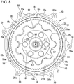
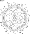
- FIG. 8 when a position at which the internal tooth 33b of the first swing gear 13 is engaged with the external tooth 60a of the output part 15 is approximately on the right side in FIG. 8 , as shown in FIG. 9 , a position at which the penetration hole 42 of the second swing gear 14 is engaged with the protrusion part 62 of the output part 15 becomes a position (approximately on the left side in FIG. 9 ) displaced by 180° around the motor shaft line L1. It is assumed that both of FIG. 8 and FIG. 9 are seen from the same direction in the axial direction.
- the embodiment described above includes the eccentric shaft 11 having the first eccentric part 25 and the second eccentric part 26 that are displaced by 180° around the motor shaft line L1 from each other.
- Each of the swing gears 13, 14 is provided on each of the eccentric parts 25, 26. Therefore, it is possible to balance the weights of eccentric amounts mutually by the first eccentric part 25 and the second eccentric part 26. Further, the first swing gear 13 and the second swing gear 14 are moved point-symmetrically around the motor shaft line L1, and therefore, it is possible to balance out the engagement reaction force between the internal tooth 33b of the first swing gear 13 and the external tooth 60a of the output part 15 and the engagement reaction force between the penetration hole 42 of the second swing gear 14 and the protrusion part 62 of the output part 15.
- the tooth number of the internal tooth 33b of the first swing gear 13 and the number of the penetration hole 42 of the second swing gear 14 are set to be smaller than the tooth numbers of the external tooth 33a of the first swing gear 13, the external tooth 41c of the second swing gear 14, and the internal tooth 27a of the ring gear 12. Therefore, the circle pitch of the internal tooth 33b of the first swing gear 13 is greater than that of the external tooth 33a of the first swing gear 13. As a result, it is possible to ensure a space between teeth of the internal tooth 33b of the first swing gear 13. By using this space, it is possible to form the penetration hole 32 on the first swing gear 13, and it is possible to engage the protrusion part 62 of the output part 15 with the second swing gear 14 via the penetration hole 32.
- the first swing gear 13 and the second swing gear 14 are overlapped with each other in the axial direction and using the penetration holes 32, 42 of the swing gears 13, 14, the first swing gear 13 is engaged with the external tooth 60a of the output part 15, and the second swing gear 14 is engaged with the protrusion part 62 of the output part 15. In this way, by reducing an unnecessary space of each component that constitutes the speed reduction mechanism 3 as much as possible, it is possible to downsize the speed reduction mechanism 3.
- each of the external tooth 60a of the output gear 52 and the tooth shape arcing surface 62a of the protrusion part 62 has a cycloidal tooth profile. Therefore, it is possible to enhance the strengths of the external tooth 60a and the protrusion part 62.
- the above embodiment is described using an example in which the tooth number of the internal tooth 27a of the ring gear 12 that constitutes the engagement first stage is set to 43, and the tooth number of the external tooth 33a of the first swing gear 13 and the tooth number of the external tooth 41c of the second swing gear 14 are set to 42.
- the above embodiment is described using an example in which each of the tooth number of the internal tooth 33b of the first swing gear 13 that constitutes the engagement second stage, the number of the penetration hole 42 of the second swing gear 14, and the tooth number of the external tooth 60a of the output gear 52 is set to 9.
- the tooth number of the internal tooth 33b of the first swing gear 13, the number of the penetration hole 42 of the second swing gear 14, and the tooth number of the external tooth 60a of the output gear 52 may be the same as one another and can be arbitrarily set.
- the above embodiment is described using an example in which the output part 15 is formed of the output shaft 51 that is formed in a substantially cylinder shape which is concentric with the motor shaft line L1 and the output gear 52 that is provided on the lower end of the output shaft 51.
- the above embodiment is described using an example in which the output shaft 51 and the output gear 52 are fastened and fixed to each other by the bolt 57.
- the embodiment is not limited thereto, and the output shaft 51 and the output gear 52 may be integrally molded.
Landscapes
- Engineering & Computer Science (AREA)
- General Engineering & Computer Science (AREA)
- Mechanical Engineering (AREA)
- Retarders (AREA)
- Connection Of Motors, Electrical Generators, Mechanical Devices, And The Like (AREA)
Abstract
Description
- The present invention relates to a speed reducer-attached motor.
- Generally, as a speed reducer-attached motor, one such motor is known which includes a speed reduction mechanism that is operated by a hypocycloid speed reduction method (for example, refer to Japanese Unexamined Patent Application, First Publication No.
2016-93000 - The eccentric part has an eccentric outer circumferential surface of which the center is at an eccentric position with respect to a rotation axis line of the motor part, and the swing gear is inserted rotatably at the eccentric outer circumferential surface. The output part is rotated concentrically with the rotation axis line of the motor part.
- In such a configuration, when the eccentric part is rotated in accordance with the drive of the motor part, the swing gear performs a swing movement while being engaged with the fixed gear. The swing gear performs a rotation movement at a rotation number (rotation number of a rotation movement) having a more decreased speed (engagement first stage) than that of the rotation number of a revolution movement according to the engagement with the fixed gear. The rotation movement having a decreased speed of the swing gear is transmitted to the output part, and the output part is rotated at a rotation number having a more increased speed (engagement second stage) than that of the rotation number of the swing gear.
- In a reducer-attached motor, there is a possibility that poor weight balance of the eccentric part or the swing gear performing a swing movement may cause a vibration or noise at the time of driving of the reducer-attached motor. Therefore, it is conceivable that a balance weight be provided in order to adjust a load balance at the time of driving (in order to balance with the eccentric mass of the eccentric part). However, for example, when thinning the diameter of the speed reduction mechanism, there is a problem in that it is difficult to ensure an arrangement space of the balance weight.
- Further, an engagement reaction force between the swing gear and the fixed gear and an engagement reaction force between the swing gear and the output gear are applied on the eccentric part. Therefore, there is a possibility that the power transmission efficiency of the speed reduction mechanism may be degraded due to these reaction forces.
- In view of the foregoing, an aspect of the present invention provides a high-efficiency and compact speed reducer-attached motor capable of adjusting a load balance at the time of driving without providing a balance weight.
- A speed reducer-attached motor according to an aspect of the present invention includes: a motor part; and a speed reduction mechanism that reduces a speed of a rotation of the motor part and that outputs a rotation having a reduced speed, wherein the speed reduction mechanism includes: a gear casing; a first eccentric part of which a center is at an eccentric position with respect to a rotation axis line of the motor part and which is rotated in response to the rotation of the motor part; a second eccentric part of which a center is at a position that is displaced by 180° around the rotation axis line from the center of the first eccentric part and which is rotated integrally with the first eccentric part in response to the rotation of the motor part; a first swing gear that is fitted rotatably to the first eccentric part and that has a first external tooth and a first internal tooth; a second swing gear that is fitted rotatably to the second eccentric part and that has a second external tooth and a second internal tooth; a fixed gear that is fixed to the gear casing and that has a third internal tooth which is engaged with the first external tooth and the second external tooth; and an output gear that has a third external tooth which is engaged with the first internal tooth and the second internal tooth, that is rotated around the rotation axis line, and that outputs power to an external apparatus, wherein tooth numbers of the first internal tooth, the second internal tooth, and the third external tooth are set to be smaller than tooth numbers of the first external tooth, the second external tooth, and the third internal tooth.
- In this way, since the first eccentric part and the second eccentric part are displaced by 180° around the rotation axis line from each other, it is possible to balance the weights of eccentric amounts mutually by the first eccentric part and the second eccentric part. Further, each of the swing gears (first swing gear, second swing gear) is rotatably fitted to each of the first eccentric part and the second eccentric part. The first swing gear and the second swing gear are moved point-symmetrically around the rotation axis line, and therefore, it is possible to balance out the engagement reaction force between the first external tooth and the third internal tooth and the engagement reaction force between the second external tooth and the third internal tooth. Further, it is possible to balance out the engagement reaction force between the first internal tooth and the third external tooth and the engagement reaction force between the second internal tooth and the third external tooth. Accordingly, it is possible to adjust a load balance at the time of driving without providing a balance weight as in the related art, and it is possible to provide a high-efficiency speed reducer-attached motor.
- Further, since the tooth numbers of the first internal tooth, the second internal tooth, and the third external tooth are set to be smaller than the tooth numbers of the first external tooth, the second external tooth, and the third internal tooth, it is possible to ensure a space between teeth of the first internal tooth, the second internal tooth, and the third external tooth. By using this space, it is possible to engage the first internal tooth with the third external tooth, and it is possible to engage the second internal tooth with the third external tooth. Therefore, it is possible to downsize the speed reducer-attached motor.
- In the speed reducer-attached motor described above, the first swing gear may have a first gear main body that is rotatably fitted to the first eccentric part and that has a circular plate shape, the first external tooth and the first internal tooth being provided on the first gear main body, the second swing gear may have a second gear main body that is rotatably fitted to the second eccentric part and that has a circular plate shape, the second external tooth and the second internal tooth being provided on the second gear main body, the first swing gear and the second swing gear may be arranged such that the first gear main body and the second gear main body are overlapped with each other in the rotation axis line direction, and a penetration hole through which the third external tooth of the output gear is capable of being inserted may be formed on each of the first gear main body and the second gear main body.
- According to such a configuration, it is possible to arrange the first swing gear, the second swing gear, the fixed gear, and the output gear in a small space. Although the space is small, it is possible to engage the first internal tooth with the third external tooth, and it is possible to engage the second internal tooth with the third external tooth.
- In the speed reducer-attached motor described above, the tooth numbers of the first internal tooth, the second internal tooth, and the third external tooth may be set to be the same as one another.
- According to such a configuration, it is possible to form the first internal tooth, the second internal tooth, and the third external tooth to be as large as possible. Therefore, it is possible to enhance strengths of the first internal tooth, the second internal tooth, and the third external tooth as much as possible.
- In the speed reducer-attached motor described above, the third external tooth may have a cycloidal tooth profile.
- According to such a configuration, it is possible to enhance the strength of the third external tooth. Further, since it is possible to allow the contact between the third external tooth and the first and second internal teeth to be smooth, it is possible to reduce the engagement resistance between the teeth as much as possible. As a result, it is possible to improve the transmission efficiency of the speed reduction mechanism.
- According to an aspect of the present invention, since the first eccentric part and the second eccentric part are displaced by 180° around the rotation axis line from each other, it is possible to balance the weights of eccentric amounts mutually by the first eccentric part and the second eccentric part. Further, each of the swing gears (first swing gear, second swing gear) is rotatably fitted to each of the first eccentric part and the second eccentric part. The first swing gear and the second swing gear are moved point-symmetrically around the rotation axis line, and therefore, it is possible to balance out the engagement reaction force between the first external tooth and the third internal tooth and the engagement reaction force between the second external tooth and the third internal tooth. Further, it is possible to balance out the engagement reaction force between the first internal tooth and the third external tooth and the engagement reaction force between the second internal tooth and the third external tooth. Accordingly, it is possible to adjust a load balance at the time of driving without providing a balance weight as in the related art, and it is possible to provide a high-efficiency speed reducer-attached motor.
- Further, since the tooth numbers of the first internal tooth, the second internal tooth, and the third external tooth are set to be smaller than the tooth numbers of the first external tooth, the second external tooth, and the third internal tooth, it is possible to ensure a space between teeth of the first internal tooth, the second internal tooth, and the third external tooth. By using this space, it is possible to engage the first internal tooth and the third external tooth with each other, and it is possible to engage the second internal tooth and the third external tooth with each other. Therefore, it is possible to downsize the speed reducer-attached motor.
-
-
FIG. 1 is a perspective view of a speed reducer-attached motor in an embodiment of the present invention. -
FIG. 2 is a cross-sectional view along an axial direction of a speed reduction mechanism in the embodiment of the present invention. -
FIG. 3 is an exploded perspective view of the speed reduction mechanism in the embodiment of the present invention. -
FIG. 4 is a partially enlarged plan view seen from an axial direction of a first swing gear in the embodiment of the present invention. -
FIG. 5 is a perspective view of a second swing gear in the embodiment of the present invention. -
FIG. 6 is a plan view seen from an axial direction of the speed reduction mechanism in the embodiment of the present invention and shows a state in which a cover and an output part are removed. -
FIG. 7 is a perspective view of the output part in the embodiment of the present invention. -
FIG. 8 is a plan view seen from an axial direction showing an engagement state between the first swing gear and the output part in the embodiment of the present invention. -
FIG. 9 is a plan view seen from an axial direction showing an engagement state between the second swing gear and the output part in the embodiment of the present invention. -
- 1: speed reducer-attached motor
- 2: motor part
- 3: speed reduction mechanism
- 10: gear casing
- 12: ring gear (fixed gear)
- 13: first swing gear
- 14: second swing gear
- 15: output part
- 25: first eccentric part
- 26: second eccentric part
- 27a: internal tooth (third internal tooth)
- 32: penetration hole
- 33a: external tooth (first external tooth)
- 33b: internal tooth (first internal tooth)
- 41c: external tooth (second external tooth)
- 42: penetration hole (second internal tooth)
- 42a: tooth shape arcing part (second internal tooth)
- 52: output gear
- 60a: external tooth (third external tooth)
- 62: protrusion part
- 62a: tooth shape arcing surface (third external tooth)
- L1: motor shaft line (rotation axis line)
- O1, O2: center
- Next, an embodiment of the present invention is described with reference to the drawings.
-
FIG. 1 is a perspective view of a speed reducer-attached motor 1. - As shown in
FIG. 1 , the speed reducer-attached motor 1 includes a motor part 2 having an oblate shape and aspeed reduction mechanism 3 to which a rotation output of the motor part 2 is transmitted. A motor shaft line (rotation axis line) L1 which is a rotation center of the motor part 2 is matched with a rotation center (axis line) of anoutput shaft 51 of anoutput part 15 described later that constitutes thespeed reduction mechanism 3. - In the following description, for ease of explanation, a side from which an output is taken out from the
output shaft 51 is referred to as an upper side (upper side inFIG. 1 ), and the other side is referred to as a lower side (lower side inFIG. 1 ). That is, the motor part 2 is arranged on the lower side, and thespeed reduction mechanism 3 is arranged on the upper side. A direction along the motor shaft line L1 is simply referred to as an axial direction. A direction around the motor shaft line L1 is simply referred to as a circumferential direction. A direction orthogonal to the motor shaft line L1 is referred to as a radial direction. - The motor part 2 is constituted of a so-called DC brushless motor. The motor part 2 has a motor casing 4 having a substantially cylinder shape. A cover 6 is provided on a lower end of the motor casing 4 so as to close an opening of the motor casing 4.
- A plurality of
bolt seats 7 are formed on a substantially upper half of an outer circumferential surface of the motor casing 4 such that the plurality ofbolt seats 7 protrude toward a radially outward direction. Eachbolt seat 7 is used for fastening and fixing the motor casing 4 and agear casing 10 described later to each other by a bolt (not shown). A female screw part (not shown) is engraved on eachbolt seat 7. The bolt seats 7 are arranged at a substantially equal interval in a circumferential direction. - A stator (not shown) is fixed to an inner circumferential surface of the motor casing 4. A rotor (not shown) is provided rotatably with respect to the stator on an inner side in the radial direction of the stator. A coil (not shown) is wound around the stator. The coil is formed to be electrically connectable to an external electric source (not shown) via an
electric source window 5a that is formed as an opening on acircumferential wall 5 of the motor casing 4. When the external electric source (not shown) is electrically connected to the stator, a predetermined magnetic field is formed on the stator. The rotor is rotated by the magnetic field, and the rotation is further transmitted to thespeed reduction mechanism 3. -
FIG. 2 is a cross-sectional view along an axial direction of thespeed reduction mechanism 3.FIG. 3 is an exploded perspective view of thespeed reduction mechanism 3. - As shown in
FIG. 2 andFIG. 3 , thespeed reduction mechanism 3 is formed as a so-called hypocycloid speed reduction mechanism. Thespeed reduction mechanism 3 includes thegear casing 10 that is arranged on the motor casing 4, aneccentric shaft 11 that is rotatably supported by thegear casing 10, a ring gear 12 (fixed gear) that is fixed inside thegear casing 10, afirst swing gear 13 and asecond swing gear 14 that are engaged with thering gear 12, and theoutput part 15 that is engaged with thefirst swing gear 13. - The
gear casing 10 is formed in a substantially tube shape having a bottom. Thegear casing 10 is arranged such that abottom wall 16 of thegear casing 10 is directed to the motor part 2 side (lower side). That is, thebottom wall 16 of thegear casing 10 has a role of closing an opening at an upper end of the motor casing 4 and partitioning the motor part 2 and thespeed reduction mechanism 3. The outer diameter of the outer circumferential surface of acircumferential wall 17 in thegear casing 10 is set to be slightly smaller than the outer diameter of the outer circumferential surface in the motor casing 4. A plurality ofbolt seats 18 that extend in the axial direction are integrally molded on the outer circumferential surface of thecircumferential wall 17. The bolt seats 18 are used for fastening and fixing acover 70 described later to thegear casing 10 by a bolt (not shown). The bolt seats 18 are formed throughout the entire region in the axial direction of thecircumferential wall 17 and are arranged at an equal interval in the circumferential direction. Afemale screw part 18a is engraved along the axial direction on eachbolt seat 18. - An
outer flange part 19 is formed on an end portion on the motor casing 4 side of thecircumferential wall 17. The outer diameter of theouter flange part 19 is set to be substantially the same as the outer diameter of the outer circumferential surface in the motor casing 4. Abolt seat 20 is formed on theouter flange part 19 at each of positions that correspond to thebolt seats 7 of the motor casing 4 such that thebolt seat 20 protrudes toward a radially outward direction. The bolt seats 7 and 20 are overlapped with each other in the axial direction. Abolt insertion hole 20a is formed on eachbolt seat 20 of thegear casing 10. A bolt (not shown) is threaded into the female screw part (not shown) that is engraved on thebolt seat 7 of the motor casing 4 via thebolt insertion hole 20a. Thereby, the motor casing 4 and thegear casing 10 are fastened and fixed to each other. - A bearing
housing 21 is integrally molded on the center in the radial direction of thebottom wall 16 of thegear casing 10. The bearinghousing 21 is formed in a substantially oval shape when seen from the axial direction. Abearing 22 is provided on the bearinghousing 21 at the center in the radial direction of thebottom wall 16. The bearing 22 rotatably supports a lower part of theeccentric shaft 11 described later. - The
ring gear 12 is internally fitted and fixed to an inner circumferential surface of thecircumferential wall 17 of thegear casing 10. Thering gear 12 is formed in a substantially tube shape having a bottom so as to correspond to the inner surface of thegear casing 10. That is, thering gear 12 is formed so as to almost cover the inner surface of thecircumferential wall 17 and the inner surface of thebottom wall 16 in thegear casing 10. Aninternal tooth 27a (third internal tooth) is formed on the entire inner circumferential surface of acircumferential wall 27 of thering gear 12. - A
fit protrusion part 28a is formed entirely on a bottom wall 28 of thering gear 12 via a predetermined gap from theinternal tooth 27a such that thefit protrusion part 28a protrudes upward. In other words, thefit protrusion part 28a is formed on most of the center part in the radial direction of the bottom wall 28 of thering gear 12 such that thefit protrusion part 28a protrudes upward. Thefit protrusion part 28a is formed in a substantially circular shape when seen from the axial direction. Thefit protrusion part 28a is used for regulating the displacement in the radial direction of the second swing gear 14 (details are described later). - A
fit hole 28a that has a substantially oval shape and that is capable of fitting to the bearinghousing 21 of thegear casing 10 is formed on the bottom wall 28 of thering gear 12. Thefit hole 28a of thering gear 12 is fitted to the bearinghousing 21 of thegear casing 10, and thereby, it is regulated that thering gear 12 is rotated around the motor shaft line L1. - The
eccentric shaft 11 that is supported by the bearing 22 of thegear casing 10 has a shaftmain body 23 that is concentric with the motor shaft line L1. A lower end of the shaftmain body 23 is rotatably supported by thebearing 22. Aconnection shaft 24 that protrudes toward the motor part 2 side is integrally molded on the lower end of the shaftmain body 23 via thebearing 22. Theconnection shaft 24 is connected to the rotor (not shown) of the motor part 2 via a joint (not shown). Thereby, the rotation of the rotor is transmitted to theeccentric shaft 11. - Two
eccentric parts eccentric part 25 and a secondeccentric part 26, are integrally molded on the center in the axial direction of the shaftmain body 23. Each of the twoeccentric parts eccentric part 25 is arranged on an upper side. The secondeccentric part 26 is arranged on a lower side. An outer circumferential surface 25a of the firsteccentric part 25 is formed of a cylindrical surface having a center 01 at an eccentric position with respect to the motor shaft line L1. An outer circumferential surface 26a of the secondeccentric part 26 is formed of a cylindrical surface having a center O2 at an eccentric position with respect to the motor shaft line L1. An eccentric amount of the center 01 of the firsteccentric part 25 is set to be the same as an eccentric amount of the center O2 of the secondeccentric part 26. The firsteccentric part 25 and the secondeccentric part 26 are arranged such that the centers 01, O2 are displaced by 180° around the motor shaft line L1 from each other. That is, the center 01 of the firsteccentric part 25 and the center O2 of the secondeccentric part 26 are at point-symmetric positions around the motor shaft line L1. - The
first swing gear 13 is rotatably supported by the firsteccentric part 25 via abearing 29. Thefirst swing gear 13 has a first gearmain body 31 having a substantially circular plate shape. Thefirst swing gear 13 is arranged on an inner side in the radial direction of thecircumferential wall 27 of thering gear 12. A bearingaccommodation hole 31a to which an outer circumferential surface of thebearing 29 is fitted is formed on the center in the radial direction of the first gearmain body 31. - An external
internal tooth ring 33 is provided on an outer circumferential part of the first gearmain body 31 to stand toward an upward direction. - An
external tooth 33a (first external tooth) that is engaged with theinternal tooth 27a of thering gear 12 is formed on an outer circumferential surface of the externalinternal tooth ring 33. Aninternal tooth 33b (first internal tooth) is formed on an inner circumferential surface of the externalinternal tooth ring 33. - The tooth number of the
internal tooth 33b is set to be smaller than the tooth number of theexternal tooth 33a and the tooth number of theinternal tooth 27a of thering gear 12. Specifically, for example, the tooth number of theinternal tooth 27a of thering gear 12 is set to 43, and the tooth number of theexternal tooth 33a of thefirst swing gear 13 is set to 42. On the other hand, the tooth number of theinternal tooth 33b of thefirst swing gear 13 is set to 9. Therefore, the circle pitch of theinternal tooth 33b is greater than that of theexternal tooth 33a. -
FIG. 4 is a partially enlarged plan view seen from an axial direction of thefirst swing gear 13. - As shown in
FIG. 4 , apenetration hole 32 that penetrates in a thickness direction is formed between teeth of theinternal tooth 33b on the first gearmain body 31 of thefirst swing gear 13. About half of an inner circumferential edge of thepenetration hole 32 is a toothshape arcing part 32a that is formed along the shape of the tooth bottom between teeth of theinternal tooth 33b. About the other half of the inner circumferential edge of thepenetration hole 32 is anarc part 32b that continues smoothly to the toothshape arcing part 32a. The toothshape arcing part 32a has a cycloidal tooth profile. -
FIG. 5 is a perspective view of thesecond swing gear 14. - As shown in
FIG. 2 ,FIG. 3 , andFIG. 5 , thesecond swing gear 14 is rotatably supported by the secondeccentric part 26 of theeccentric shaft 11 via abearing 40. Thesecond swing gear 14 has a second gearmain body 41 having a substantially circular plate shape. Thesecond swing gear 14 is arranged on an inner side in the radial direction of thecircumferential wall 27 of thering gear 12 and on a lower surface side of the first gearmain body 31. A bearingaccommodation hole 41a to which an outer circumferential surface of thebearing 40 is fitted is formed on the center in the radial direction of the second gearmain body 41. - A
fit recess part 41b is formed on most of the center part in the radial direction of a lower surface of the second gearmain body 41. Thefit recess part 41b is loosely fitted to thefit protrusion part 28a that is formed on the bottom wall 28 of thering gear 12. Thereby, a displacement in the radial direction of thesecond swing gear 14 is regulated. - An
external tooth 41c (second external tooth) that is engaged with theinternal tooth 27a of thering gear 12 is formed on an outer circumferential part of the second gearmain body 41. The tooth number of theexternal tooth 41c is set to be the same as the tooth number of theexternal tooth 33a of thefirst swing gear 13. - A penetration hole 42 (second internal tooth) is formed on the second gear
main body 41 at a position that corresponds to thepenetration hole 32 of thefirst swing gear 13 and at a position from an upper surface of the second gearmain body 41 to thefit recess part 41b. Thepenetration hole 42 is formed in the same shape as that of thepenetration hole 32 of thefirst swing gear 13. That is, half on an outer side in the radial direction of an inner circumferential edge of thepenetration hole 42 is a toothshape arcing part 42a (second internal tooth), and the other half on an inner side in the radial direction of the inner circumferential edge of thepenetration hole 42 is anarc part 42b that continues smoothly to the toothshape arcing part 42a. The toothshape arcing part 42a has a cycloidal tooth profile. - As shown in
FIG. 5 in detail, an outermost position at which thepenetration hole 42 is formed is arranged at a slightly more outside position in the radial direction than thefit recess part 41b. Therefore, when seeing thesecond swing gear 14 from an upper side (thefirst swing gear 13 side), the circumferential edge of thefit recess part 41b becomes a state of being partially exposed via thepenetration hole 42. -
FIG. 6 is a plan view seen from an axial direction of a state in which theeccentric shaft 11, thering gear 12, thefirst swing gear 13, and thesecond swing gear 14 are stored inside thegear casing 10. - As described above, the
first swing gear 13 is rotatably supported by the firsteccentric part 25 of theeccentric shaft 11 via thebearing 29, and thesecond swing gear 14 is rotatably supported by the secondeccentric part 26 via thebearing 40. Therefore, as shown inFIG. 6 , thepenetration hole 32 of thefirst swing gear 13 and thepenetration hole 42 of thesecond swing gear 14 are formed at a position that corresponds to each other, but the positions of the penetration holes 32, 42 are not matched with each other when seen from the axial direction. That is, thepenetration hole 32 of thefirst swing gear 13 and thepenetration hole 42 of thesecond swing gear 14 are displaced by 180° around the motor shaft line L1. -
FIG. 7 is a perspective view of theoutput part 15. - As shown in
FIG. 2 ,FIG. 3 , andFIG. 7 , theoutput part 15 is arranged on thefirst swing gear 13 and on an inner side in the radial direction of the externalinternal tooth ring 33 of thefirst swing gear 13. - The
output part 15 is formed of theoutput shaft 51 that is formed in a substantially cylinder shape which is concentric with the motor shaft line L1 and anoutput gear 52 that is provided on a lower end of theoutput shaft 51. Theoutput gear 52 is arranged on thefirst swing gear 13 and the inner side in the radial direction of the externalinternal tooth ring 33 of thefirst swing gear 13. - A
connection shaft 53 to which a two-direction removal processing is applied is integrally molded on a front end of theoutput shaft 51 concentrically with theoutput shaft 51. Afemale screw part 53a is engraved on theconnection shaft 53. Theconnection shaft 53 is used for outputting an output of the speed reducer-attached motor 1 to an external apparatus (now shown) by being connected to the external apparatus (not shown). - A
flange part 54 having a substantially circular plate shape is integrally molded on a lower end of theoutput shaft 51. A bearinghousing 55 is formed on a lower surface of theflange part 54 such that the bearinghousing 55 protrudes downward. Abearing 56 is internally fitted and fixed to the bearinghousing 55. An upper end part of theeccentric shaft 11 is rotatably supported by thebearing 56. - A
bolt insertion hole 58 through which abolt 57 is capable of being inserted is formed on an outer circumferential portion of theflange part 54. A counterboring portion 58a that receives ahead part 57a of thebolt 57 is formed on an upper surface of thebolt insertion hole 58. By forming the counterboring portion 58a, when thebolt 57 is inserted in thebolt insertion hole 58, it is possible to prevent thehead part 57a of thebolt 57 from protruding from theflange part 54. Thebolt 57 that is inserted in thebolt insertion hole 58 fastens and fixes theoutput shaft 51 and theoutput gear 52 to each other. - The
output gear 52 has a gearmain body 60 having a substantially circular plate shape. Astorage recess part 61 is formed on most of the center part in the radial direction of an upper surface of the gearmain body 60. The diameter of thestorage recess part 61 is set to be slightly larger than the diameter of theflange part 54. Theflange part 54 of theoutput shaft 51 is stored in such astorage recess part 61. Afemale screw part 61a is engraved on thestorage recess part 61 at a position that corresponds to thebolt insertion hole 58 of theflange part 54. Abolt 57 that is inserted into thebolt insertion hole 58 is threaded into thefemale screw part 61a. Thereby, theoutput shaft 51 and theoutput gear 52 are fastened and fixed to each other. - An
external tooth 60a (third external tooth) that is concentric with the motor shaft line L1 is formed on an outer circumferential part of the gearmain body 60. Theexternal tooth 60a has a cycloidal tooth profile. Theexternal tooth 60a is engaged with theinternal tooth 33b of thefirst swing gear 13. - The
external tooth 60a has aprotrusion part 62 that is formed to protrude along the axial direction and toward a downward direction. Theprotrusion part 62 is inserted in thepenetration hole 32 of thefirst swing gear 13 and is further inserted in thepenetration hole 42 of thesecond swing gear 14. A surface that continues to theexternal tooth 60a of theprotrusion part 62 is a toothshape arcing surface 62a (third external tooth) having a cycloidal tooth profile similarly to theexternal tooth 60a. A surface on an inner side in the radial direction other than the toothshape arcing surface 62a of theprotrusion part 62 is anarc surface 62b that smoothly continues to the toothshape arcing surface 62a. Thereby, theprotrusion part 62 is inserted in thepenetration hole 42 of thesecond swing gear 14 and is engaged with thepenetration hole 42. - As shown in
FIG. 1 andFIG. 2 , thecover 70 is attached to an upper end of thegear casing 10 in a state where theeccentric shaft 11, thering gear 12, thefirst swing gear 13, thesecond swing gear 14, and theflange part 54 of theoutput part 15 are stored inside thegear casing 10. - The
cover 70 is formed of a covermain body 71 that is formed in a substantially circular plate shape so as to close an opening of thecircumferential wall 17 of thegear casing 10 and a bearinghousing 72 that is formed to protrude upward from the covermain body 71. - A spigot-and-socket
fit part 73 that has an annular shape and that is fitted by spigot-and-socket fitting to thecircumferential wall 17 of thegear casing 10 is formed to protrude on a lower surface of the covermain body 71. Positioning in the radial direction of thecover 70 with respect to thegear casing 10 is performed by the spigot-and-socketfit part 73. A front end of the spigot-and-socketfit part 73 is in contact with an upper end of thecircumferential wall 27 of thering gear 12. - A
bolt seat 74 is formed on an outer circumferential edge of the covermain body 71 at each of positions that correspond to the bolt seats 18 of thegear casing 10 such that thebolt seat 74 protrudes outward in the radial direction. Abolt insertion hole 74a that communicates with thefemale screw part 18a (refer toFIG. 3 ) of thegear casing 10 is formed on eachbolt seat 74. A bolt (not shown) is threaded into thefemale screw part 18a of thegear casing 10 via thebolt insertion hole 74a. Thereby, thegear casing 10 and thecover 70 are fastened and fixed to each other. - The bearing
housing 72 is formed in a substantially cylinder shape and is arranged concentrically with the motor shaft line L1. An upper end of theoutput shaft 51 protrudes upward in the axial direction of thecover 70 via the bearinghousing 72. - Each of
bearings housing 72. Theoutput shaft 51 is rotatably supported by thebearings collar 76 is provided between the twobearings housing 72. - The
collar 76 performs positioning in the axial direction of the twobearings - Next, an operation of the speed reducer-attached motor 1 is described.
- The rotor (not shown) of the motor part 2 is rotated, and thereby, the
eccentric shaft 11 that is connected to the rotor is rotated. When theeccentric shaft 11 is rotated, thefirst swing gear 13 and thesecond swing gear 14 are rotated in response to the rotation. Thefirst swing gear 13 is supported rotatably via thebearing 29 by the firsteccentric part 25 of theeccentric shaft 11. Thesecond swing gear 14 is supported rotatably via thebearing 40 by the secondeccentric part 26 of theeccentric shaft 11. Therefore, each of the swing gears 13, 14 revolves around the motor shaft line L1 and is rotated such that the speed is reduced with respect to theeccentric shaft 11 around each of the corresponding centers 01, O2 (refer toFIG. 2 ) of theeccentric parts 25, 26 (engagement first stage). - The
first swing gear 13 of the two swing gears 13, 14 is engaged with theoutput gear 52. Therefore, by the swinging rotation of thefirst swing gear 13, power is transmitted to the first swing gear 13 (engagement second stage), and theoutput part 15 is rotated. Thereby, the drive force of the speed reducer-attached motor 1 is output. - The first
eccentric part 25 and the secondeccentric part 26 are arranged such that the centers 01, O2 are displaced by 180° around the motor shaft line L1 from each other. In other words, the center 01 of the firsteccentric part 25 and the center O2 of the secondeccentric part 26 are at point-symmetric positions around the motor shaft line L1. That is, thepenetration hole 32 of thefirst swing gear 13 and thepenetration hole 42 of thesecond swing gear 14 are displaced by 180° around the motor shaft line L1. Therefore, thefirst swing gear 13 and thesecond swing gear 14 perform a swing movement while being displaced by 180° around the motor shaft line L1. As a result, a timing when theinternal tooth 33b of thefirst swing gear 13 is engaged with theexternal tooth 60a of theoutput part 15 and a timing when thepenetration hole 42 of thesecond swing gear 14 is engaged with theprotrusion part 62 of theoutput part 15 are displaced by 180° around the motor shaft line L1 from each other. - That is, as shown in
FIG. 8 , when a position at which theinternal tooth 33b of thefirst swing gear 13 is engaged with theexternal tooth 60a of theoutput part 15 is approximately on the right side inFIG. 8 , as shown inFIG. 9 , a position at which thepenetration hole 42 of thesecond swing gear 14 is engaged with theprotrusion part 62 of theoutput part 15 becomes a position (approximately on the left side inFIG. 9 ) displaced by 180° around the motor shaft line L1. It is assumed that both ofFIG. 8 andFIG. 9 are seen from the same direction in the axial direction. - In this way, the embodiment described above includes the
eccentric shaft 11 having the firsteccentric part 25 and the secondeccentric part 26 that are displaced by 180° around the motor shaft line L1 from each other. Each of the swing gears 13, 14 is provided on each of theeccentric parts eccentric part 25 and the secondeccentric part 26. Further, thefirst swing gear 13 and thesecond swing gear 14 are moved point-symmetrically around the motor shaft line L1, and therefore, it is possible to balance out the engagement reaction force between theinternal tooth 33b of thefirst swing gear 13 and theexternal tooth 60a of theoutput part 15 and the engagement reaction force between thepenetration hole 42 of thesecond swing gear 14 and theprotrusion part 62 of theoutput part 15. Further, it is possible to balance out the engagement reaction force between theinternal tooth 27a of thering gear 12 and theexternal tooth 33a of thefirst swing gear 13 and the engagement reaction force between theinternal tooth 27a of thering gear 12 and theexternal tooth 41c of thesecond swing gear 14. Accordingly, it is possible to adjust a load balance at the time of driving of thespeed reduction mechanism 3 without providing a balance weight as in the related art, and it is possible to provide a high-efficiency speed reducer-attached motor 1. - Further, the tooth number of the
internal tooth 33b of thefirst swing gear 13 and the number of thepenetration hole 42 of thesecond swing gear 14 are set to be smaller than the tooth numbers of theexternal tooth 33a of thefirst swing gear 13, theexternal tooth 41c of thesecond swing gear 14, and theinternal tooth 27a of thering gear 12. Therefore, the circle pitch of theinternal tooth 33b of thefirst swing gear 13 is greater than that of theexternal tooth 33a of thefirst swing gear 13. As a result, it is possible to ensure a space between teeth of theinternal tooth 33b of thefirst swing gear 13. By using this space, it is possible to form thepenetration hole 32 on thefirst swing gear 13, and it is possible to engage theprotrusion part 62 of theoutput part 15 with thesecond swing gear 14 via thepenetration hole 32. Therefore, it is possible to downsize the speed reduction mechanism 3 (speed reducer-attached motor 1). Further, as the tooth number of theinternal tooth 33b of thefirst swing gear 13 is small, it is possible to form theinternal tooth 33b and theexternal tooth 60a of theoutput part 15 to be large. Therefore, it is possible to enhance the strengths of theinternal tooth 33b and theexternal tooth 60a as much as possible. - Further, by arranging the
first swing gear 13 and thesecond swing gear 14 to be overlapped with each other in the axial direction and using the penetration holes 32, 42 of the swing gears 13, 14, thefirst swing gear 13 is engaged with theexternal tooth 60a of theoutput part 15, and thesecond swing gear 14 is engaged with theprotrusion part 62 of theoutput part 15. In this way, by reducing an unnecessary space of each component that constitutes thespeed reduction mechanism 3 as much as possible, it is possible to downsize thespeed reduction mechanism 3. - Further, each of the
external tooth 60a of theoutput gear 52 and the toothshape arcing surface 62a of theprotrusion part 62 has a cycloidal tooth profile. Therefore, it is possible to enhance the strengths of theexternal tooth 60a and theprotrusion part 62. - Further, it is possible to allow the contact of the
external tooth 60a of theoutput gear 52 and theprotrusion part 62 with theinternal tooth 33b of thefirst swing gear 13 and thepenetration hole 42 of thesecond swing gear 14 to be smooth. Therefore, it is possible to reduce the engagement resistance between theexternal tooth 60a and theprotrusion part 62, and theinternal tooth 33b and thepenetration hole 42 as much as possible. As a result, it is possible to improve the transmission efficiency of thespeed reduction mechanism 3. - The present invention is not limited to the embodiment described above, and various changes can be added to the embodiment described above without departing from the scope of the invention.
- For example, the above embodiment is described using an example in which the tooth number of the
internal tooth 27a of thering gear 12 that constitutes the engagement first stage is set to 43, and the tooth number of theexternal tooth 33a of thefirst swing gear 13 and the tooth number of theexternal tooth 41c of thesecond swing gear 14 are set to 42. The above embodiment is described using an example in which each of the tooth number of theinternal tooth 33b of thefirst swing gear 13 that constitutes the engagement second stage, the number of thepenetration hole 42 of thesecond swing gear 14, and the tooth number of theexternal tooth 60a of theoutput gear 52 is set to 9. However, the embodiment is not limited thereto. The tooth number of theinternal tooth 33b of thefirst swing gear 13, the number of thepenetration hole 42 of thesecond swing gear 14, and the tooth number of theexternal tooth 60a of theoutput gear 52 may be the same as one another and can be arbitrarily set. - Further, the above embodiment is described using an example in which the
output part 15 is formed of theoutput shaft 51 that is formed in a substantially cylinder shape which is concentric with the motor shaft line L1 and theoutput gear 52 that is provided on the lower end of theoutput shaft 51. The above embodiment is described using an example in which theoutput shaft 51 and theoutput gear 52 are fastened and fixed to each other by thebolt 57. However, the embodiment is not limited thereto, and theoutput shaft 51 and theoutput gear 52 may be integrally molded.
Claims (4)
- A speed reducer-attached motor, comprising:a motor part; anda speed reduction mechanism that reduces a speed of a rotation of the motor part and that outputs a rotation having a reduced speed,wherein the speed reduction mechanism comprises:a gear casing;a first eccentric part of which a center is at an eccentric position with respect to a rotation axis line of the motor part and which is rotated in response to the rotation of the motor part;a second eccentric part of which a center is at a position that is displaced by 180° around the rotation axis line from the center of the first eccentric part and which is rotated integrally with the first eccentric part in response to the rotation of the motor part;a first swing gear that is fitted rotatably to the first eccentric part and that has a first external tooth and a first internal tooth;a second swing gear that is fitted rotatably to the second eccentric part and that has a second external tooth and a second internal tooth;a fixed gear that is fixed to the gear casing and that has a third internal tooth which is engaged with the first external tooth and the second external tooth; andan output gear that has a third external tooth which is engaged with the first internal tooth and the second internal tooth, that is rotated around the rotation axis line, and that outputs power to an external apparatus,wherein tooth numbers of the first internal tooth, the second internal tooth, and the third external tooth are set to be smaller than tooth numbers of the first external tooth, the second external tooth, and the third internal tooth.
- The speed reducer-attached motor according to Claim 1,
wherein the first swing gear has a first gear main body that is rotatably fitted to the first eccentric part and that has a circular plate shape, the first external tooth and the first internal tooth being provided on the first gear main body,
the second swing gear has a second gear main body that is rotatably fitted to the second eccentric part and that has a circular plate shape, the second external tooth and the second internal tooth being provided on the second gear main body,
the first swing gear and the second swing gear are arranged such that the first gear main body and the second gear main body are overlapped with each other in the rotation axis line direction, and
a penetration hole through which the third external tooth of the output gear is capable of being inserted is formed on each of the first gear main body and the second gear main body. - The speed reducer-attached motor according to Claim 1 or 2,
wherein the tooth numbers of the first internal tooth, the second internal tooth, and the third external tooth are set to be the same as one another. - The speed reducer-attached motor according to any one of Claims 1 to 3,
wherein the third external tooth has a cycloidal tooth profile.
Applications Claiming Priority (1)
| Application Number | Priority Date | Filing Date | Title |
|---|---|---|---|
| JP2017159388A JP6873867B2 (en) | 2017-08-22 | 2017-08-22 | Motor with reducer |
Publications (1)
| Publication Number | Publication Date |
|---|---|
| EP3467344A1 true EP3467344A1 (en) | 2019-04-10 |
Family
ID=63143070
Family Applications (1)
| Application Number | Title | Priority Date | Filing Date |
|---|---|---|---|
| EP18187062.7A Withdrawn EP3467344A1 (en) | 2017-08-22 | 2018-08-02 | Speed reducer-attached motor |
Country Status (2)
| Country | Link |
|---|---|
| EP (1) | EP3467344A1 (en) |
| JP (1) | JP6873867B2 (en) |
Cited By (3)
| Publication number | Priority date | Publication date | Assignee | Title |
|---|---|---|---|---|
| CN114222060A (en) * | 2021-11-29 | 2022-03-22 | 新思考电机有限公司 | Output assembly, optical drive device and security equipment |
| CN116235388A (en) * | 2020-09-24 | 2023-06-06 | 日本电产株式会社 | Cycloidal reduction gear and electrical equipment |
| US20250341245A1 (en) * | 2024-05-03 | 2025-11-06 | Delta Electronics, Inc. | Inner gear wheel with impact absorption structure and reducer using same |
Citations (4)
| Publication number | Priority date | Publication date | Assignee | Title |
|---|---|---|---|---|
| JP2012161239A (en) * | 2011-01-11 | 2012-08-23 | Jtekt Corp | Motor driving force transmission device |
| EP2538112A1 (en) * | 2010-02-15 | 2012-12-26 | JTEKT Corporation | Swing internal contact type planetary gear device and rotation drive device |
| WO2016072453A1 (en) * | 2014-11-06 | 2016-05-12 | 株式会社ミツバ | Motor with speed reducer |
| US20160297500A1 (en) * | 2015-04-07 | 2016-10-13 | Tangent Motor Company | Electric Drive Unit |
Family Cites Families (2)
| Publication number | Priority date | Publication date | Assignee | Title |
|---|---|---|---|---|
| DE102004048196A1 (en) * | 2004-09-30 | 2006-04-06 | Robert Bosch Gmbh | Eccentric gear, in particular with cycloid gearing |
| CN101150269A (en) * | 2007-06-28 | 2008-03-26 | 张东烁 | Multi-milkiness tooth planet drive and reverse rotation prevention decelerating motor |
-
2017
- 2017-08-22 JP JP2017159388A patent/JP6873867B2/en active Active
-
2018
- 2018-08-02 EP EP18187062.7A patent/EP3467344A1/en not_active Withdrawn
Patent Citations (5)
| Publication number | Priority date | Publication date | Assignee | Title |
|---|---|---|---|---|
| EP2538112A1 (en) * | 2010-02-15 | 2012-12-26 | JTEKT Corporation | Swing internal contact type planetary gear device and rotation drive device |
| JP2012161239A (en) * | 2011-01-11 | 2012-08-23 | Jtekt Corp | Motor driving force transmission device |
| WO2016072453A1 (en) * | 2014-11-06 | 2016-05-12 | 株式会社ミツバ | Motor with speed reducer |
| JP2016093000A (en) | 2014-11-06 | 2016-05-23 | 株式会社ミツバ | Reducer motor |
| US20160297500A1 (en) * | 2015-04-07 | 2016-10-13 | Tangent Motor Company | Electric Drive Unit |
Cited By (5)
| Publication number | Priority date | Publication date | Assignee | Title |
|---|---|---|---|---|
| CN116235388A (en) * | 2020-09-24 | 2023-06-06 | 日本电产株式会社 | Cycloidal reduction gear and electrical equipment |
| CN114222060A (en) * | 2021-11-29 | 2022-03-22 | 新思考电机有限公司 | Output assembly, optical drive device and security equipment |
| CN114222060B (en) * | 2021-11-29 | 2023-12-26 | 新思考电机有限公司 | Output components, optical drives and security equipment |
| US20250341245A1 (en) * | 2024-05-03 | 2025-11-06 | Delta Electronics, Inc. | Inner gear wheel with impact absorption structure and reducer using same |
| US12510135B2 (en) * | 2024-05-03 | 2025-12-30 | Delta Electronics, Inc. | Inner gear wheel with impact absorption structure and reducer using same |
Also Published As
| Publication number | Publication date |
|---|---|
| JP6873867B2 (en) | 2021-05-19 |
| JP2019041438A (en) | 2019-03-14 |
Similar Documents
| Publication | Publication Date | Title |
|---|---|---|
| JP6154640B2 (en) | Motor with reduction gear | |
| US11162574B2 (en) | Speed reduction mechanism and motor with speed reducer | |
| TWI656714B (en) | Harmonic gear reducer unit and power unit provided with the unit | |
| EP3239526B1 (en) | Electrically driven scroll compressor | |
| JP6599220B2 (en) | Reducer with electric motor | |
| CN109478826B (en) | power unit | |
| EP2597761A2 (en) | Electric motor and electric unit including the same | |
| US20190085906A1 (en) | Transmission and actuator | |
| JP6873867B2 (en) | Motor with reducer | |
| KR20240113033A (en) | Swivel Actuator of Hollow Type | |
| US11181178B2 (en) | Strain wave gear speed reducer unit and power unit | |
| JP5824668B2 (en) | Ring body holding jig and scroll compression device | |
| CN217883114U (en) | Output device | |
| CN216290514U (en) | Electric Actuator | |
| WO2020183896A1 (en) | Electric compressor | |
| EP3453916B1 (en) | Speed reducer-attached motor | |
| JP2006304558A (en) | Hypocycloid reducer with built-in motor | |
| JP5884707B2 (en) | Electric compressor | |
| JP7250874B2 (en) | Power unit and robot having it | |
| JP2007162497A (en) | Electric motor and fluid pump using the electric motor | |
| EP4521605A1 (en) | Actuator | |
| JP2006300273A (en) | Hypocycloid reducer with built-in motor | |
| JP2019173658A (en) | Electric compressor | |
| KR20240114338A (en) | Motor Driving Apparatus and Swivel Actuator of Hollow Type Using the Same | |
| JP2025043441A (en) | Speed reducer and motor with speed reducer |
Legal Events
| Date | Code | Title | Description |
|---|---|---|---|
| PUAI | Public reference made under article 153(3) epc to a published international application that has entered the european phase |
Free format text: ORIGINAL CODE: 0009012 |
|
| STAA | Information on the status of an ep patent application or granted ep patent |
Free format text: STATUS: THE APPLICATION HAS BEEN PUBLISHED |
|
| AK | Designated contracting states |
Kind code of ref document: A1 Designated state(s): AL AT BE BG CH CY CZ DE DK EE ES FI FR GB GR HR HU IE IS IT LI LT LU LV MC MK MT NL NO PL PT RO RS SE SI SK SM TR |
|
| AX | Request for extension of the european patent |
Extension state: BA ME |
|
| STAA | Information on the status of an ep patent application or granted ep patent |
Free format text: STATUS: REQUEST FOR EXAMINATION WAS MADE |
|
| 17P | Request for examination filed |
Effective date: 20191010 |
|
| RBV | Designated contracting states (corrected) |
Designated state(s): AL AT BE BG CH CY CZ DE DK EE ES FI FR GB GR HR HU IE IS IT LI LT LU LV MC MK MT NL NO PL PT RO RS SE SI SK SM TR |
|
| STAA | Information on the status of an ep patent application or granted ep patent |
Free format text: STATUS: EXAMINATION IS IN PROGRESS |
|
| 17Q | First examination report despatched |
Effective date: 20200625 |
|
| GRAP | Despatch of communication of intention to grant a patent |
Free format text: ORIGINAL CODE: EPIDOSNIGR1 |
|
| STAA | Information on the status of an ep patent application or granted ep patent |
Free format text: STATUS: GRANT OF PATENT IS INTENDED |
|
| INTG | Intention to grant announced |
Effective date: 20210303 |
|
| STAA | Information on the status of an ep patent application or granted ep patent |
Free format text: STATUS: THE APPLICATION IS DEEMED TO BE WITHDRAWN |
|
| 18D | Application deemed to be withdrawn |
Effective date: 20210714 |