EP3466725A1 - Pneumatic tire - Google Patents
Pneumatic tire Download PDFInfo
- Publication number
- EP3466725A1 EP3466725A1 EP17806078.6A EP17806078A EP3466725A1 EP 3466725 A1 EP3466725 A1 EP 3466725A1 EP 17806078 A EP17806078 A EP 17806078A EP 3466725 A1 EP3466725 A1 EP 3466725A1
- Authority
- EP
- European Patent Office
- Prior art keywords
- microgroove
- crossing
- microgrooves
- blocks
- pneumatic tire
- Prior art date
- Legal status (The legal status is an assumption and is not a legal conclusion. Google has not performed a legal analysis and makes no representation as to the accuracy of the status listed.)
- Granted
Links
- 230000007423 decrease Effects 0.000 description 12
- 238000005096 rolling process Methods 0.000 description 12
- XLYOFNOQVPJJNP-UHFFFAOYSA-N water Substances O XLYOFNOQVPJJNP-UHFFFAOYSA-N 0.000 description 12
- 230000006866 deterioration Effects 0.000 description 7
- 238000005452 bending Methods 0.000 description 3
- 230000000052 comparative effect Effects 0.000 description 3
- IJGRMHOSHXDMSA-UHFFFAOYSA-N Atomic nitrogen Chemical compound N#N IJGRMHOSHXDMSA-UHFFFAOYSA-N 0.000 description 1
- 230000001154 acute effect Effects 0.000 description 1
- 229910001873 dinitrogen Inorganic materials 0.000 description 1
- 230000000694 effects Effects 0.000 description 1
- 238000011156 evaluation Methods 0.000 description 1
- 230000005484 gravity Effects 0.000 description 1
- 238000010438 heat treatment Methods 0.000 description 1
Images


Classifications
-
- B—PERFORMING OPERATIONS; TRANSPORTING
- B60—VEHICLES IN GENERAL
- B60C—VEHICLE TYRES; TYRE INFLATION; TYRE CHANGING; CONNECTING VALVES TO INFLATABLE ELASTIC BODIES IN GENERAL; DEVICES OR ARRANGEMENTS RELATED TO TYRES
- B60C11/00—Tyre tread bands; Tread patterns; Anti-skid inserts
- B60C11/03—Tread patterns
- B60C11/12—Tread patterns characterised by the use of narrow slits or incisions, e.g. sipes
- B60C11/1259—Depth of the sipe
-
- B—PERFORMING OPERATIONS; TRANSPORTING
- B60—VEHICLES IN GENERAL
- B60C—VEHICLE TYRES; TYRE INFLATION; TYRE CHANGING; CONNECTING VALVES TO INFLATABLE ELASTIC BODIES IN GENERAL; DEVICES OR ARRANGEMENTS RELATED TO TYRES
- B60C11/00—Tyre tread bands; Tread patterns; Anti-skid inserts
- B60C11/03—Tread patterns
- B60C11/0306—Patterns comprising block rows or discontinuous ribs
-
- B—PERFORMING OPERATIONS; TRANSPORTING
- B60—VEHICLES IN GENERAL
- B60C—VEHICLE TYRES; TYRE INFLATION; TYRE CHANGING; CONNECTING VALVES TO INFLATABLE ELASTIC BODIES IN GENERAL; DEVICES OR ARRANGEMENTS RELATED TO TYRES
- B60C11/00—Tyre tread bands; Tread patterns; Anti-skid inserts
- B60C11/03—Tread patterns
-
- B—PERFORMING OPERATIONS; TRANSPORTING
- B60—VEHICLES IN GENERAL
- B60C—VEHICLE TYRES; TYRE INFLATION; TYRE CHANGING; CONNECTING VALVES TO INFLATABLE ELASTIC BODIES IN GENERAL; DEVICES OR ARRANGEMENTS RELATED TO TYRES
- B60C11/00—Tyre tread bands; Tread patterns; Anti-skid inserts
- B60C11/03—Tread patterns
- B60C11/04—Tread patterns in which the raised area of the pattern consists only of continuous circumferential ribs, e.g. zig-zag
-
- B—PERFORMING OPERATIONS; TRANSPORTING
- B60—VEHICLES IN GENERAL
- B60C—VEHICLE TYRES; TYRE INFLATION; TYRE CHANGING; CONNECTING VALVES TO INFLATABLE ELASTIC BODIES IN GENERAL; DEVICES OR ARRANGEMENTS RELATED TO TYRES
- B60C11/00—Tyre tread bands; Tread patterns; Anti-skid inserts
- B60C11/03—Tread patterns
- B60C11/11—Tread patterns in which the raised area of the pattern consists only of isolated elements, e.g. blocks
-
- B—PERFORMING OPERATIONS; TRANSPORTING
- B60—VEHICLES IN GENERAL
- B60C—VEHICLE TYRES; TYRE INFLATION; TYRE CHANGING; CONNECTING VALVES TO INFLATABLE ELASTIC BODIES IN GENERAL; DEVICES OR ARRANGEMENTS RELATED TO TYRES
- B60C11/00—Tyre tread bands; Tread patterns; Anti-skid inserts
- B60C11/03—Tread patterns
- B60C11/12—Tread patterns characterised by the use of narrow slits or incisions, e.g. sipes
-
- B—PERFORMING OPERATIONS; TRANSPORTING
- B60—VEHICLES IN GENERAL
- B60C—VEHICLE TYRES; TYRE INFLATION; TYRE CHANGING; CONNECTING VALVES TO INFLATABLE ELASTIC BODIES IN GENERAL; DEVICES OR ARRANGEMENTS RELATED TO TYRES
- B60C11/00—Tyre tread bands; Tread patterns; Anti-skid inserts
- B60C11/03—Tread patterns
- B60C11/12—Tread patterns characterised by the use of narrow slits or incisions, e.g. sipes
- B60C11/1204—Tread patterns characterised by the use of narrow slits or incisions, e.g. sipes with special shape of the sipe
-
- B—PERFORMING OPERATIONS; TRANSPORTING
- B60—VEHICLES IN GENERAL
- B60C—VEHICLE TYRES; TYRE INFLATION; TYRE CHANGING; CONNECTING VALVES TO INFLATABLE ELASTIC BODIES IN GENERAL; DEVICES OR ARRANGEMENTS RELATED TO TYRES
- B60C11/00—Tyre tread bands; Tread patterns; Anti-skid inserts
- B60C11/03—Tread patterns
- B60C11/12—Tread patterns characterised by the use of narrow slits or incisions, e.g. sipes
- B60C11/1236—Tread patterns characterised by the use of narrow slits or incisions, e.g. sipes with special arrangements in the tread pattern
-
- B—PERFORMING OPERATIONS; TRANSPORTING
- B60—VEHICLES IN GENERAL
- B60C—VEHICLE TYRES; TYRE INFLATION; TYRE CHANGING; CONNECTING VALVES TO INFLATABLE ELASTIC BODIES IN GENERAL; DEVICES OR ARRANGEMENTS RELATED TO TYRES
- B60C11/00—Tyre tread bands; Tread patterns; Anti-skid inserts
- B60C11/03—Tread patterns
- B60C2011/0337—Tread patterns characterised by particular design features of the pattern
- B60C2011/0339—Grooves
- B60C2011/0341—Circumferential grooves
- B60C2011/0346—Circumferential grooves with zigzag shape
-
- B—PERFORMING OPERATIONS; TRANSPORTING
- B60—VEHICLES IN GENERAL
- B60C—VEHICLE TYRES; TYRE INFLATION; TYRE CHANGING; CONNECTING VALVES TO INFLATABLE ELASTIC BODIES IN GENERAL; DEVICES OR ARRANGEMENTS RELATED TO TYRES
- B60C11/00—Tyre tread bands; Tread patterns; Anti-skid inserts
- B60C11/03—Tread patterns
- B60C11/12—Tread patterns characterised by the use of narrow slits or incisions, e.g. sipes
- B60C11/1204—Tread patterns characterised by the use of narrow slits or incisions, e.g. sipes with special shape of the sipe
- B60C2011/1209—Tread patterns characterised by the use of narrow slits or incisions, e.g. sipes with special shape of the sipe straight at the tread surface
-
- B—PERFORMING OPERATIONS; TRANSPORTING
- B60—VEHICLES IN GENERAL
- B60C—VEHICLE TYRES; TYRE INFLATION; TYRE CHANGING; CONNECTING VALVES TO INFLATABLE ELASTIC BODIES IN GENERAL; DEVICES OR ARRANGEMENTS RELATED TO TYRES
- B60C11/00—Tyre tread bands; Tread patterns; Anti-skid inserts
- B60C11/03—Tread patterns
- B60C11/12—Tread patterns characterised by the use of narrow slits or incisions, e.g. sipes
- B60C11/1204—Tread patterns characterised by the use of narrow slits or incisions, e.g. sipes with special shape of the sipe
- B60C2011/1213—Tread patterns characterised by the use of narrow slits or incisions, e.g. sipes with special shape of the sipe sinusoidal or zigzag at the tread surface
-
- B—PERFORMING OPERATIONS; TRANSPORTING
- B60—VEHICLES IN GENERAL
- B60C—VEHICLE TYRES; TYRE INFLATION; TYRE CHANGING; CONNECTING VALVES TO INFLATABLE ELASTIC BODIES IN GENERAL; DEVICES OR ARRANGEMENTS RELATED TO TYRES
- B60C11/00—Tyre tread bands; Tread patterns; Anti-skid inserts
- B60C11/03—Tread patterns
- B60C11/12—Tread patterns characterised by the use of narrow slits or incisions, e.g. sipes
- B60C11/1259—Depth of the sipe
- B60C2011/1268—Depth of the sipe being different from sipe to sipe
-
- B—PERFORMING OPERATIONS; TRANSPORTING
- B60—VEHICLES IN GENERAL
- B60C—VEHICLE TYRES; TYRE INFLATION; TYRE CHANGING; CONNECTING VALVES TO INFLATABLE ELASTIC BODIES IN GENERAL; DEVICES OR ARRANGEMENTS RELATED TO TYRES
- B60C2200/00—Tyres specially adapted for particular applications
- B60C2200/06—Tyres specially adapted for particular applications for heavy duty vehicles
-
- Y—GENERAL TAGGING OF NEW TECHNOLOGICAL DEVELOPMENTS; GENERAL TAGGING OF CROSS-SECTIONAL TECHNOLOGIES SPANNING OVER SEVERAL SECTIONS OF THE IPC; TECHNICAL SUBJECTS COVERED BY FORMER USPC CROSS-REFERENCE ART COLLECTIONS [XRACs] AND DIGESTS
- Y02—TECHNOLOGIES OR APPLICATIONS FOR MITIGATION OR ADAPTATION AGAINST CLIMATE CHANGE
- Y02T—CLIMATE CHANGE MITIGATION TECHNOLOGIES RELATED TO TRANSPORTATION
- Y02T10/00—Road transport of goods or passengers
- Y02T10/80—Technologies aiming to reduce greenhouse gasses emissions common to all road transportation technologies
- Y02T10/86—Optimisation of rolling resistance, e.g. weight reduction
Definitions
- the present disclosure relates to a pneumatic tire having at least one main groove formed in each of tread portions on both sides of the tire equator.
- Patent Document 1 A pneumatic tire described in the following Japanese Patent Application Laid-Open ( JP-A) No. 2015-074360 (Patent Document 1), for example, is known as a conventional pneumatic tire.
- each land portion is formed with a plurality of microgrooves extending along a tire meridian, and a plurality of crossing microgrooves that are orthogonal to the microgrooves and extend along the tire equator as illustrated in Fig. 4 of Patent Document 1.
- block groups each consisting of a plurality of blocks having rectangular shapes aligned along the microgrooves are repeatedly arranged in each land portion in the circumferential direction. Consequently, the blocks are methodically arranged in a grid pattern.
- a pneumatic tire having a plurality of blocks as described above has a problem that the wet performance drastically deteriorates as described below.
- the block 51 is crushed inward in the radial direction upon receiving a load when the block 51 enters into a grounded region. Since rubber constituting the block 51 is incompressible, all of the four sidewalls 52 bulge perpendicularly to the sidewalls 52 at this time.
- the amount of bulging of the sidewalls 52 described above increases from both lateral ends (ridgelines extending in the height direction) 52a of each sidewall 52 toward the intermediate point between the lateral ends and increases from both vertical ends (radially inner and outer ends) of each sidewall 52 toward the intermediate point between the vertical ends as indicated by the imaginary lines, and the vicinity of the surface center (the center of gravity) of each sidewall 52 becomes the peak of the mountain where the sidewall bulges most.
- the ground contact pressure on the surface at the radially outer end of the block 51 is high at an outer edge portion, that is, in the vicinity of the open end edges 57, and low at a center portion of the surface.
- the blocks 51 arranged in a grid pattern enter into the grounded region as described above, a large part of the groove 53 is closed by the bulging deformation described above, the ground contact pressure in the vicinity of the open end edges 57 of each block 51 is lowered, and the ground contact pressure on the surface of each block 51 is uniformized.
- An object of the present disclosure is to provide a pneumatic tire capable of easily improving wet performance while preventing deterioration of rolling resistance.
- Such an object is achieved by a pneumatic tire in which at least one main groove is formed in each tread portion on either side of the tire equator S to form a plurality of land portions, a microgroove that extends in the width direction and closes at a time of grounding, and a crossing microgroove that crosses the microgroove and closes at the time of grounding are formed in at least one of the land portions, such that block groups, each consisting of a plurality of blocks aligned along the microgroove, are arranged in at least one of the land portions repeatedly in the circumferential direction, and widthwise sidewalls of blocks in block groups arranged adjacent to each other in the circumferential direction are displaced from each other along the microgroove by a distance L corresponding to from 1/3 to 1/2 of an arrangement pitch P of the blocks.
- a pneumatic radial tire to be mounted on a truck, a bus, or a passenger car.
- the pneumatic tire 11 is used in a state in which air, nitrogen gas, or the like is filled therein.
- the pneumatic tire 11 has a tread portion 12, which is grounded at the time of running, at a radially outer end portion.
- At least one main groove 13 is formed in each tread portion 12 on either side of the tire equator (tread center) S.
- two main grooves 13 are formed in each of the tread portions, that is, four in total are formed. Consequently, one proximal land portion 14 extending on the tire equator S is defined between two inner main grooves 13a in closest proximity to the tire equator S.
- two intermediate land portions 15 are defined between the inner main grooves 13a and two outer main grooves 13b respectively arranged on outer sides in the width direction than the inner main grooves 13a.
- two outer land portions 16 are defined between the outer main grooves 13b and tread ends E.
- a plurality of, for example five here, land portions are formed in the tread portion 12 to extend along the tire equator S.
- one main groove or three main grooves may be provided in each of tread portions 12 on both sides of the tire equator S, that is, two or six in total may be provided.
- one main groove may be formed on the tire equator S in addition to the above-described main groove.
- the main groove may extend straight.
- a plurality of microgrooves 19 extending in the width direction are formed in at least one land portion, or for example one proximal land portion 14 that is in closest proximity to the tire equator S by straddling the tire equator S in this embodiment, among the land portions.
- the microgrooves 19 extend parallel to each other and are arranged at equal intervals in the extending direction of the tire equator S.
- the microgrooves 19 have a groove width within a range of from 0.5 to 3.0 mm so as to close at the time of grounding, and are generally referred to as sipes.
- the above-mentioned width direction refers to a direction that crosses the tire meridian G, which is orthogonal to the tire equator S, at an angle of 45 degrees or less and includes a direction parallel to the tire meridian G.
- At least one crossing microgroove 21, for example one crossing microgroove 21 here, is formed in each defined land portion 20 (see FIG. 4 ) defined between two adjacent microgrooves 19.
- the crossing microgrooves 21 cross the microgrooves 19 at a predetermined angle, for example 90 degrees here, and both ends thereof are continuous with the microgrooves 19 forming a substantially T shape.
- the crossing microgrooves 21 are arranged at equal intervals in the extending direction of the microgrooves 19. It is to be noted that it is preferable that the crossing angle of the crossing microgrooves 21 with respect to the microgrooves 19 is approximately 90 degrees in order to uniformize the block rigidity as a whole.
- the crossing microgrooves 21 also have a groove width within the range of from 0.5 to 3.0 mm so as to close at the time of grounding and are also referred to as sipes as with the microgrooves 19.
- microgrooves 19 which extend in the width direction and close at the time of grounding, and crossing microgrooves 21 which cross the microgrooves 19 and close at the time of grounding in at least one land portion (proximal land portion 14) as described above, block groups 23 each consisting of a plurality of (two) blocks 22 aligned at equal intervals along the microgrooves 19 are formed in the land portion (proximal land portion 14), and such block groups 23 are repeatedly arranged at equal intervals in the circumferential direction.
- the circumferential direction refers to a direction crossing the tire equator S at an angle of less than 45 degrees and includes a direction parallel to the tire equator S.
- the contact area between the sidewalls of the blocks 22 at this portion also decreases.
- a space that is not closed in the microgrooves 19 and the crossing microgrooves 21 increases. Consequently, when the pneumatic tire 11 runs on a wet road surface, a space into which water can enter increases, the cross-sectional area of where water flows also increases, and the wet performance is easily improved.
- a sidewall of a block 22 is deformed to expand as described above, a measurable part of the microgrooves 19 and the crossing microgrooves 21 is not closed. Therefore, a portion having a high ground contact pressure remains in the vicinity of the open end edge 25 of each block 22, and consequently, the wet performance is further improved.
- the arrangement pitch P of the blocks 22 refers to the distance between the same points in blocks 22 adjacent to each other in the width direction, and is a value measured along the extending direction of a microgroove 19.
- the value of the distance L is less than 1/3 of the arrangement pitch P, it is impossible to improve the wet performance, as is clear from the test examples described later.
- the amount of overlap with a block 22 adjacent in the width direction becomes larger than the amount of overlap with a block 22 which has overlapped so far, and therefore the distance L is to be measured between the adjacent blocks 22. Consequently, the maximum value of the distance L is 1/2.
- microgrooves 19 may be extended parallel to the tire meridian G direction in a state where block groups 23 (blocks 22) shifted in the width direction as described above are arranged repeatedly in the circumferential direction.
- block groups 23 blocks 22
- such a structure may possibly cause deterioration of the wet performance when the inner main grooves 13a bend acutely (at 90 degrees) to have a rectangular wave shape, and the flow of water flowing therein is deteriorated.
- the microgrooves 19 are inclined at a predetermined angle with respect to the tire meridian G as described above, so that acute bending toward the width direction of the inner main grooves 13a located on both sides of the width direction of the land portion (proximal land portion 14) provided with the blocks 22 is relaxed.
- the flow of water at the time of draining is smoothed, and the wet performance is improved.
- corner portions protruding outward in the width direction of the blocks 22 disappear as indicated by the imaginary lines, so that the bending degree of the inner main grooves 13a is further reduced, and the wet performance is further improved.
- the shape slightly changes from the quadrangle shape by providing a disappearing portion, though the blocks 22 have the same quadrangle shape, for example a rectangle shape here, in a case in which such a disappearing portion is not provided in the blocks 22.
- blocks 22 adjacent to each other in the width direction may be slightly displaced relatively along the crossing microgroove 21.
- the inclination direction of the microgrooves 19 with respect to the tire equator S is opposite to the inclination direction of the crossing microgrooves 21 with respect to the tire equator S.
- the crush amount of a block 22 becomes large (the bulging amount of a sidewall also becomes large) and the contribution ratio to the wet performance becomes large in a portion of the pneumatic tire 11 adjacent to to the tire equator S, that is, in the tread center portion since the ground contact pressure is made higher than that of the shoulder portion by the crowning, it is possible to improve the wet performance not only at this portion but also at the entire area of the pneumatic tire 11 in a case in which the microgrooves 19 and the crossing microgrooves 21 are formed in the proximal land portion 14 in closest proximity to the tire equator S, which greatly contributes to improvement of the wet performance, as described above.
- microgrooves 19 and crossing microgrooves 21 similar to those described above may be formed at any land portion except the proximal land portion 14, and widthwise sidewalls 24 of blocks 22 may be displaced along the microgrooves 19 by a distance L corresponding to from 1/3 to 1/2 of the arrangement pitch P of the blocks 22.
- Denoted at 28 are a plurality of transverse grooves, which are formed respectively in the intermediate land portions 15 and have both widthwise ends that are open to the inner and outer main grooves 13a and 13b, are spaced at equal intervals in the circumferential direction, and extend in the width direction, and these transverse grooves 28 divide the intermediate land portions 15, so that a plurality of intermediate blocks 29 spaced in the circumferential direction are defined.
- Denoted at 30 are a plurality of transverse grooves respectively formed in the outer land portions 16, and these transverse grooves 30 each have a widthwise inner end open to an outer main groove 13b, and a widthwise outer end open to a tread end E.
- the transverse grooves 30 extend in the width direction and are arranged at equal intervals in the circumferential direction, the outer land portions 16 are divided by the transverse grooves 30, so that a plurality of outer blocks 31 separated in the circumferential direction are defined. It is to be noted that the transverse grooves 28 and 30 may be omitted, and in such a case, the intermediate land portions 15 and the outer land portions 16 become ribs continuous in the circumferential direction.
- Fig. 3 is a view illustrating Embodiment 2 of the invention and is a sectional view similar to Fig. 2 .
- a groove depth D of the microgrooves 19 and the crossing microgrooves 21 formed in the proximal land portion 14 is set larger than a groove depth F of the inner main grooves 13a that come into contact with the proximal land portions 14 at both widthwise outer sides of the proximal land portion 14.
- the groove depth of the microgrooves 19 and the crossing microgrooves 21 is set larger than the groove depth of the outer main grooves in a case in which the microgrooves and the crossing microgrooves are formed in the intermediate land portions.
- the other configurations and functions are the same as those of Embodiment 1.
- Figs. 4 and 5 are view illustrating Embodiment 3 of the present invention.
- microgrooves 34 and crossing microgrooves 35 similar to the microgrooves 19 and the crossing microgrooves 21 are formed also in the land portion other than the proximal land portion 14, for example in the intermediate land portion 33 here, so that a plurality of blocks 36 are defined in the intermediate land portions 33 by the microgrooves 34 and the crossing microgrooves 35.
- a groove depth H of the microgrooves 19 and the crossing microgrooves 21 formed in the proximal land portion 14 is set larger than a groove depth J of the microgrooves 34 and the crossing microgrooves 35 formed in a land portion other than the proximal land portion 14 (in the intermediate land portion 33 here).
- Figs. 6 and 7 are views illustrating Embodiment 4 of the present invention.
- the proximal land portion 14 and the intermediate land portions 15 are integrated to form a wide proximal land portion 38, and microgrooves 39 similar to the microgrooves 19 and crossing microgrooves 40 similar to the crossing microgrooves 21 are formed in the proximal land portion 38, so that a plurality of blocks 41 are defined in the proximal land portion 38 by the microgrooves 39 and the crossing microgrooves 40.
- three crossing microgrooves 40 parallel to each other are formed and arranged at equal intervals in the extending direction of each microgroove 39 in this embodiment.
- a groove depth Q of the microgrooves 39 and the crossing microgrooves 40 located in a proximal portion M adjacent to the tire equator S among the microgrooves 39 and the crossing microgrooves 40 formed in the proximal land portion 38, is larger than a groove depth R of the microgrooves 39 and the crossing microgrooves 40 located in a distal portion N spaced from the tire equator S.
- the groove depth of a portion of the microgrooves 39 and the crossing microgrooves 40 located closer to the tire equator S large as described above so as to facilitate crushing of the blocks 41 at the time of grounding, sidewalls of blocks 41 come into contact with each other over a large area at the time of grounding. Consequently, the rigidity of these blocks 41 is improved, and the rolling resistance decreases.
- the groove depth of the microgrooves 39 and the crossing microgrooves 40 are increased stepwise as approaching the tire equator S in this embodiment, it is to be noted that the groove depth may be increased continuously in the present disclosure.
- each block was adjusted to set the groove width of the inner main grooves and the amplitude of the zigzag to be the same value.
- the size of each of the above-described tires was 275/80R22.5, and the groove depths of the main grooves, the microgrooves, and the crossing microgrooves were the same.
- each of such tires was mounted on a rim having a size of 7.50 ⁇ 22.5, and the inside of each tire was filled to have an internal pressure (gauge pressure) of 900 kPa.
- Each tire was then mounted on a heavy-weight vehicle. Thereafter, such a vehicle was run on a wet road surface, and the wet performance (steering stability) at the time of running was evaluated and indexed based on feeling of the driver. Here, the larger the numerical value is, the better the wet performance is.
- index evaluation of the rolling resistance of each tire was carried out by running each of the above-described tires on a drum at 70 km/h, and then inertially rotating the drum and measuring the degree of deceleration during inertial rotation.
- the present disclosure can be applied to the industrial field of a pneumatic tire having at least one main groove formed in each tread portion on either side of the tire equator.
Landscapes
- Engineering & Computer Science (AREA)
- Mechanical Engineering (AREA)
- Tires In General (AREA)
Abstract
Description
- The present disclosure relates to a pneumatic tire having at least one main groove formed in each of tread portions on both sides of the tire equator.
- A pneumatic tire described in the following Japanese Patent Application Laid-Open (
JP-A) No. 2015-074360 - In such a pneumatic tire, three land portions are formed by forming one main groove in each of tread portions on both sides of the tire equator, and each land portion is provided with a plurality of microgrooves extending along a tire meridian, and a plurality of crossing microgrooves that are orthogonal to the microgrooves and extend along the tire equator as illustrated in
Fig. 4 of Patent Document 1. As a result, block groups each consisting of a plurality of blocks having rectangular shapes aligned along the microgrooves are repeatedly arranged in each land portion in the circumferential direction. Consequently, the blocks are methodically arranged in a grid pattern. - Here, a pneumatic tire having a plurality of blocks as described above has a problem that the wet performance drastically deteriorates as described below. When focusing on one block as illustrated in
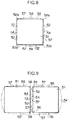
Fig. 8 , theblock 51 is crushed inward in the radial direction upon receiving a load when theblock 51 enters into a grounded region. Since rubber constituting theblock 51 is incompressible, all of the foursidewalls 52 bulge perpendicularly to thesidewalls 52 at this time. Here, the amount of bulging of thesidewalls 52 described above increases from both lateral ends (ridgelines extending in the height direction) 52a of eachsidewall 52 toward the intermediate point between the lateral ends and increases from both vertical ends (radially inner and outer ends) of eachsidewall 52 toward the intermediate point between the vertical ends as indicated by the imaginary lines, and the vicinity of the surface center (the center of gravity) of eachsidewall 52 becomes the peak of the mountain where the sidewall bulges most. - When two
blocks 51 bulging in such a manner are aligned such thatsidewalls 52 are opposed to each other over the entire surface with amicrogroove 53, which closes at a time of grounding, interposed therebetween as illustrated inFig. 9 , the vicinities of the most bulging tops are opposed right in front. Therefore, the bulgingportions 54 crush each other, and theopposed sidewalls 52 of the twoblocks 51 come into surface contact with each other over a wide area around a surface center portion. In addition, when the bulgingportions 54 crush each other as described above, rubber that has not been absorbed by thegroove 53 causescorners 56 of twosidewalls 55 that are orthogonal to theopposed sidewalls 52 of the twoblocks 51 to bulge as indicated by the imaginary lines inFig. 9 . Here, whenblocks 51 havingsidewalls 52 deformed in such a manner are arranged in a grid pattern as described in the Patent Document 1,corner portions 56 ofadjacent blocks 51 also bulge and come into closer surface contact with each other. Thus, a large part of thegroove 53 betweenadjacent blocks 51 is closed by the surface contact between thesidewalls 52 of theblocks 51. Consequently, when the pneumatic tire runs on a wet road surface, the wet performance deteriorates, and since a space into which water can enter is narrowed, the cross-sectional area of where water flows decreases. - Moreover, when focusing on one
block 51, the ground contact pressure on the surface at the radially outer end of theblock 51 is high at an outer edge portion, that is, in the vicinity of theopen end edges 57, and low at a center portion of the surface. However, when theblocks 51 arranged in a grid pattern enter into the grounded region as described above, a large part of thegroove 53 is closed by the bulging deformation described above, the ground contact pressure in the vicinity of theopen end edges 57 of eachblock 51 is lowered, and the ground contact pressure on the surface of eachblock 51 is uniformized. Here, in a case in which a portion having a high ground contact pressure exists on the surface of theblock 51 as described above, such a portion destroys the water film on the road surface and comes into contact with the road surface at the time of grounding. Therefore, although the contact area increases and the wet performance is improved, the water film is not sufficiently destroyed and the wet performance is further deteriorated in a case in which a portion having a high ground contact pressure decreases and the ground contact pressure is uniformized as a whole as described above. Although it is conceivable to increase the width of thegroove 53 located betweenblocks 51 in order to solve such a problem, this causes another problem that the amount of deformation of theblock 51 during running increases and the heating value increases, causing deterioration of the rolling resistance of the pneumatic tire. - An object of the present disclosure is to provide a pneumatic tire capable of easily improving wet performance while preventing deterioration of rolling resistance.
- Such an object is achieved by a pneumatic tire in which at least one main groove is formed in each tread portion on either side of the tire equator S to form a plurality of land portions, a microgroove that extends in the width direction and closes at a time of grounding, and a crossing microgroove that crosses the microgroove and closes at the time of grounding are formed in at least one of the land portions, such that block groups, each consisting of a plurality of blocks aligned along the microgroove, are arranged in at least one of the land portions repeatedly in the circumferential direction, and widthwise sidewalls of blocks in block groups arranged adjacent to each other in the circumferential direction are displaced from each other along the microgroove by a distance L corresponding to from 1/3 to 1/2 of an arrangement pitch P of the blocks.
- When the pneumatic tire rotates and a block enters into the grounded region, the block is crushed by a load, and each sidewall of the block bulges such that the vicinity of the surface center becomes the top of the mountain (becomes the most bulging portion). However, with the present disclosure in which the widthwise sidewalls of blocks in block groups arranged adjacent to each other in the circumferential direction are displaced from each other along the microgroove by a distance L corresponding to from 1/3 to 1/2 of the arrangement pitch P of the blocks as described above, the most bulging portions in blocks adjacent to each other in the circumferential direction collapse largely along the microgroove, and as a result, crushing of the most bulging portions is avoided, and the contact area between the block sidewalls decreases. Moreover, since crushing of the most bulging portions is avoided as described above, the amount of bulging in the vicinity of the corner portions of the blocks also decreases, and the contact area between the block sidewalls at this portion decreases. Thus, a space which is not closed in the microgrooves and the crossing microgrooves increases. Consequently, when the pneumatic tire runs on a wet road surface, the space into which water can enter increases, the cross-sectional area of where water flows also increases, and the wet performance is easily improved. In addition, even when the block sidewalls are deformed to bulge as described above, a measurable part of each of the microgrooves and the crossing microgrooves is not closed, and therefore a portion having a high ground contact pressure remains in the vicinity of the open end edge of each block. Consequently, the wet performance is further improved. In such a case, since it is unnecessary to increase the groove width of the microgrooves and the crossing microgrooves, deterioration of the rolling resistance can be prevented.
-
-
Fig. 1 is a plan view of a tread portion illustrating Embodiment 1 of the invention. -
Fig. 2 is a sectional view taken along line I-I inFig. 1 . -
Fig. 3 is a sectional view similar toFig. 2 illustrating Embodiment 2 of the invention. -
Fig. 4 is a plan view of a tread portion illustrating Embodiment 3 of the invention. -
Fig. 5 is a sectional view taken along line II-II inFIG. 4 . -
Fig. 6 is a plan view of a tread portion illustrating Embodiment 4 of the invention. -
Fig. 7 is a sectional view taken along line III-III inFig. 6 . -
Fig. 8 is an explanatory view for explaining a deformed state of a block in a conventional tread portion. -
Fig. 9 is an explanatory view for explaining a deformed state of blocks in a conventional tread portion. - The following description will explain Embodiment 1 of the present invention with reference to the drawings.
- Denoted at 11 in
Figs. 1 and2 is a pneumatic radial tire to be mounted on a truck, a bus, or a passenger car. Thepneumatic tire 11 is used in a state in which air, nitrogen gas, or the like is filled therein. Thepneumatic tire 11 has atread portion 12, which is grounded at the time of running, at a radially outer end portion. On the outer circumferential surface (tread surface) of thetread portion 12, a plurality ofmain grooves 13 are formed to continuously extend while bending in a zigzag manner along the tire equator S. Since themain grooves 13 are wide, themain grooves 13 do not close even at the time of grounding. Here, at least onemain groove 13 is formed in eachtread portion 12 on either side of the tire equator (tread center) S. In this embodiment, twomain grooves 13 are formed in each of the tread portions, that is, four in total are formed. Consequently, oneproximal land portion 14 extending on the tire equator S is defined between two innermain grooves 13a in closest proximity to the tire equator S. Moreover, twointermediate land portions 15 are defined between the innermain grooves 13a and two outermain grooves 13b respectively arranged on outer sides in the width direction than the innermain grooves 13a. Furthermore, twoouter land portions 16 are defined between the outermain grooves 13b and tread ends E. As a result, a plurality of, for example five here, land portions are formed in thetread portion 12 to extend along the tire equator S. In the present disclosure, one main groove or three main grooves may be provided in each oftread portions 12 on both sides of the tire equator S, that is, two or six in total may be provided. Moreover, one main groove may be formed on the tire equator S in addition to the above-described main groove. Furthermore, the main groove may extend straight. - A plurality of
microgrooves 19 extending in the width direction are formed in at least one land portion, or for example oneproximal land portion 14 that is in closest proximity to the tire equator S by straddling the tire equator S in this embodiment, among the land portions. Themicrogrooves 19 extend parallel to each other and are arranged at equal intervals in the extending direction of the tire equator S. Themicrogrooves 19 have a groove width within a range of from 0.5 to 3.0 mm so as to close at the time of grounding, and are generally referred to as sipes. Here, the above-mentioned width direction refers to a direction that crosses the tire meridian G, which is orthogonal to the tire equator S, at an angle of 45 degrees or less and includes a direction parallel to the tire meridian G. At least one crossingmicrogroove 21, for example one crossingmicrogroove 21 here, is formed in each defined land portion 20 (seeFIG. 4 ) defined between twoadjacent microgrooves 19. The crossingmicrogrooves 21 cross themicrogrooves 19 at a predetermined angle, for example 90 degrees here, and both ends thereof are continuous with themicrogrooves 19 forming a substantially T shape. In a case in which a plurality of such crossingmicrogrooves 21 are formed, thecrossing microgrooves 21 are arranged at equal intervals in the extending direction of themicrogrooves 19. It is to be noted that it is preferable that the crossing angle of thecrossing microgrooves 21 with respect to themicrogrooves 19 is approximately 90 degrees in order to uniformize the block rigidity as a whole. Thecrossing microgrooves 21 also have a groove width within the range of from 0.5 to 3.0 mm so as to close at the time of grounding and are also referred to as sipes as with themicrogrooves 19. - By forming
microgrooves 19 which extend in the width direction and close at the time of grounding, and crossingmicrogrooves 21 which cross themicrogrooves 19 and close at the time of grounding in at least one land portion (proximal land portion 14) as described above,block groups 23 each consisting of a plurality of (two)blocks 22 aligned at equal intervals along themicrogrooves 19 are formed in the land portion (proximal land portion 14), andsuch block groups 23 are repeatedly arranged at equal intervals in the circumferential direction. Here, the circumferential direction refers to a direction crossing the tire equator S at an angle of less than 45 degrees and includes a direction parallel to the tire equator S. Here, in a case in which blocks 22 in twoblock groups 23 arranged adjacent to each other in the circumferential direction completely overlap each other in the extending direction of the crossing microgrooves 21 (the extending direction of themicrogrooves 19 is not displaced) as described in the background art, a space into which water can enter is narrowed and the cross-sectional area of where water flows decreases when thepneumatic tire 11 rotates and theblock 22 enters into the grounded region as described above, and the ground contact pressure is also uniformized as a whole, causing deterioration of the wet performance. - However, in this embodiment in which widthwise sidewalls on the same side in the width direction, or for example the
widthwise sidewalls 24 on one side in the width direction here, ofblocks 22 inblock groups 23 arranged adjacent to each other in the circumferential direction are displaced along amicrogroove 19 by a distance L corresponding to from 1/3 to 1/2 of the arrangement pitch P of theblocks 22, the most bulging portions collapse largely along themicrogroove 19 inblocks 22 adjacent to each other in the circumferential direction. As a result, crushing of the most bulging portions is avoided, and the contact area between the sidewalls of theblocks 22 decreases. Moreover, by avoiding the above-described crushing of the most bulging portions, the bulging amount in the vicinity of the corner portions of theblocks 22 also decreases. As a result, the contact area between the sidewalls of theblocks 22 at this portion also decreases. Thus, a space that is not closed in themicrogrooves 19 and thecrossing microgrooves 21 increases. Consequently, when thepneumatic tire 11 runs on a wet road surface, a space into which water can enter increases, the cross-sectional area of where water flows also increases, and the wet performance is easily improved. In addition, even when a sidewall of ablock 22 is deformed to expand as described above, a measurable part of themicrogrooves 19 and thecrossing microgrooves 21 is not closed. Therefore, a portion having a high ground contact pressure remains in the vicinity of theopen end edge 25 of eachblock 22, and consequently, the wet performance is further improved. In addition, since it is unnecessary to increase the groove width of themicrogrooves 19 and thecrossing microgrooves 21 in such a case, deterioration of the rolling resistance can be easily prevented. - Here, the arrangement pitch P of the
blocks 22 refers to the distance between the same points inblocks 22 adjacent to each other in the width direction, and is a value measured along the extending direction of amicrogroove 19. In a case in which the value of the distance L is less than 1/3 of the arrangement pitch P, it is impossible to improve the wet performance, as is clear from the test examples described later. Moreover, when a relative shift occurs between theblocks 22 such that the value of the distance L exceeds 1/2 of the arrangement pitch P, the amount of overlap with ablock 22 adjacent in the width direction becomes larger than the amount of overlap with ablock 22 which has overlapped so far, and therefore the distance L is to be measured between the adjacent blocks 22. Consequently, the maximum value of the distance L is 1/2. Moreover, themicrogrooves 19 may be extended parallel to the tire meridian G direction in a state where block groups 23 (blocks 22) shifted in the width direction as described above are arranged repeatedly in the circumferential direction. However, such a structure may possibly cause deterioration of the wet performance when the innermain grooves 13a bend acutely (at 90 degrees) to have a rectangular wave shape, and the flow of water flowing therein is deteriorated. - Therefore, in this embodiment, the
microgrooves 19 are inclined at a predetermined angle with respect to the tire meridian G as described above, so that acute bending toward the width direction of the innermain grooves 13a located on both sides of the width direction of the land portion (proximal land portion 14) provided with theblocks 22 is relaxed. As a result, the flow of water at the time of draining is smoothed, and the wet performance is improved. In this embodiment, it is to be noted that corner portions protruding outward in the width direction of theblocks 22 disappear as indicated by the imaginary lines, so that the bending degree of the innermain grooves 13a is further reduced, and the wet performance is further improved. Here, the shape slightly changes from the quadrangle shape by providing a disappearing portion, though theblocks 22 have the same quadrangle shape, for example a rectangle shape here, in a case in which such a disappearing portion is not provided in theblocks 22. Moreover, in a case in which the shape of eachblock 22 is adjusted, blocks 22 adjacent to each other in the width direction may be slightly displaced relatively along thecrossing microgroove 21. - Furthermore, in this embodiment in which the
crossing microgrooves 21 cross perpendicularly with themicrogrooves 19 inclined at a predetermined angle with respect to the tire meridian G as described above, the inclination direction of themicrogrooves 19 with respect to the tire equator S is opposite to the inclination direction of thecrossing microgrooves 21 with respect to the tire equator S. Moreover, although the crush amount of ablock 22 becomes large (the bulging amount of a sidewall also becomes large) and the contribution ratio to the wet performance becomes large in a portion of thepneumatic tire 11 adjacent to to the tire equator S, that is, in the tread center portion since the ground contact pressure is made higher than that of the shoulder portion by the crowning, it is possible to improve the wet performance not only at this portion but also at the entire area of thepneumatic tire 11 in a case in which themicrogrooves 19 and thecrossing microgrooves 21 are formed in theproximal land portion 14 in closest proximity to the tire equator S, which greatly contributes to improvement of the wet performance, as described above. In the present disclosure, it is to be noted thatmicrogrooves 19 and crossingmicrogrooves 21 similar to those described above may be formed at any land portion except theproximal land portion 14, and widthwise sidewalls 24 ofblocks 22 may be displaced along themicrogrooves 19 by a distance L corresponding to from 1/3 to 1/2 of the arrangement pitch P of theblocks 22. In such a case, it is also possible to improve the wet performance in the land portion where themicrogrooves 19 and thecrossing microgrooves 21 are formed, while preventing deterioration of the rolling performance. Denoted at 28 are a plurality of transverse grooves, which are formed respectively in theintermediate land portions 15 and have both widthwise ends that are open to the inner and outermain grooves transverse grooves 28 divide theintermediate land portions 15, so that a plurality ofintermediate blocks 29 spaced in the circumferential direction are defined. Denoted at 30 are a plurality of transverse grooves respectively formed in theouter land portions 16, and thesetransverse grooves 30 each have a widthwise inner end open to an outermain groove 13b, and a widthwise outer end open to a tread end E. Since thetransverse grooves 30 extend in the width direction and are arranged at equal intervals in the circumferential direction, theouter land portions 16 are divided by thetransverse grooves 30, so that a plurality ofouter blocks 31 separated in the circumferential direction are defined. It is to be noted that thetransverse grooves intermediate land portions 15 and theouter land portions 16 become ribs continuous in the circumferential direction. -
Fig. 3 is a view illustrating Embodiment 2 of the invention and is a sectional view similar toFig. 2 . In this embodiment, a groove depth D of themicrogrooves 19 and thecrossing microgrooves 21 formed in theproximal land portion 14 is set larger than a groove depth F of the innermain grooves 13a that come into contact with theproximal land portions 14 at both widthwise outer sides of theproximal land portion 14. By setting the groove depth of themicrogrooves 19 and thecrossing microgrooves 21 closer to the tire equator S (close to the tire equator S) large as described above so as to facilitate crushing of theblock 22 at this portion, thewidthwise sidewalls 24 of theseblocks 22 come into contact with each other over a large area at the time of grounding. Consequently, the rigidity of theseblocks 22 is improved, and the rolling resistance decreases. It is to be noted that the groove depth of the microgrooves and the crossing microgrooves is set larger than the groove depth of the outer main grooves in a case in which the microgrooves and the crossing microgrooves are formed in the intermediate land portions. The other configurations and functions are the same as those of Embodiment 1. -
Figs. 4 and 5 are view illustrating Embodiment 3 of the present invention. In this embodiment,microgrooves 34 and crossingmicrogrooves 35 similar to themicrogrooves 19 and thecrossing microgrooves 21 are formed also in the land portion other than theproximal land portion 14, for example in theintermediate land portion 33 here, so that a plurality ofblocks 36 are defined in theintermediate land portions 33 by themicrogrooves 34 and thecrossing microgrooves 35. Moreover, a groove depth H of themicrogrooves 19 and thecrossing microgrooves 21 formed in theproximal land portion 14 is set larger than a groove depth J of themicrogrooves 34 and thecrossing microgrooves 35 formed in a land portion other than the proximal land portion 14 (in theintermediate land portion 33 here). By setting the groove depth H of themicrogrooves 19 and thecrossing microgrooves 21 closer to the tire equator S large as described above so as to facilitate crushing of theblocks 22, thewidthwise sidewalls 24 of theseblocks 22 come into contact with each other over a large area at the time of grounding. Consequently, the rigidity of theseblocks 22 is improved, and the rolling resistance decreases. It is to be noted that the other configurations and functions are the same as those of Embodiment 1. -
Figs. 6 and 7 are views illustrating Embodiment 4 of the present invention. In this embodiment, theproximal land portion 14 and theintermediate land portions 15 are integrated to form a wideproximal land portion 38, andmicrogrooves 39 similar to themicrogrooves 19 and crossingmicrogrooves 40 similar to thecrossing microgrooves 21 are formed in theproximal land portion 38, so that a plurality ofblocks 41 are defined in theproximal land portion 38 by themicrogrooves 39 and thecrossing microgrooves 40. Furthermore, three crossingmicrogrooves 40 parallel to each other are formed and arranged at equal intervals in the extending direction of eachmicrogroove 39 in this embodiment. Moreover, a groove depth Q of themicrogrooves 39 and thecrossing microgrooves 40 located in a proximal portion M adjacent to the tire equator S among themicrogrooves 39 and thecrossing microgrooves 40 formed in theproximal land portion 38, is larger than a groove depth R of themicrogrooves 39 and thecrossing microgrooves 40 located in a distal portion N spaced from the tire equator S. By setting the groove depth of a portion of themicrogrooves 39 and thecrossing microgrooves 40 located closer to the tire equator S large as described above so as to facilitate crushing of theblocks 41 at the time of grounding, sidewalls ofblocks 41 come into contact with each other over a large area at the time of grounding. Consequently, the rigidity of theseblocks 41 is improved, and the rolling resistance decreases. Although the groove depth of themicrogrooves 39 and thecrossing microgrooves 40 are increased stepwise as approaching the tire equator S in this embodiment, it is to be noted that the groove depth may be increased continuously in the present disclosure. - Next, a test example will be described. In this test, Conventional Tire having the above-described value L (distance) / P (arrangement pitch) of 0/12 (crossing microgrooves are on a straight line), Comparative Tire 1 having a value L/P of 2/12, Comparative Tire 2 having a value L/P of 3/12, Example Tire 1 having a value L/P of 4/12, Example Tire 2 having a value L/P of 5/12, and Example Tire 3 having a value L/P of 6/12 were prepared. Here, the tread pattern of each tire was substantially the same as that depicted in
Fig. 1 , except that a disappearing shape of each block was adjusted to set the groove width of the inner main grooves and the amplitude of the zigzag to be the same value. Here, the size of each of the above-described tires was 275/80R22.5, and the groove depths of the main grooves, the microgrooves, and the crossing microgrooves were the same. - Next, each of such tires was mounted on a rim having a size of 7.50×22.5, and the inside of each tire was filled to have an internal pressure (gauge pressure) of 900 kPa. Each tire was then mounted on a heavy-weight vehicle. Thereafter, such a vehicle was run on a wet road surface, and the wet performance (steering stability) at the time of running was evaluated and indexed based on feeling of the driver. Here, the larger the numerical value is, the better the wet performance is. Next, index evaluation of the rolling resistance of each tire was carried out by running each of the above-described tires on a drum at 70 km/h, and then inertially rotating the drum and measuring the degree of deceleration during inertial rotation. Here, the smaller the numerical value is, the less the rolling resistance is, which indicates that the better the tire is. The following Table 1 shows the results of such a test. As is clear from this test result, the wet performance can be effectively improved without lowering the rolling resistance in a case in which the value of L/P is within the range of from 1/3 to 1/2.
[Table 1] TYPE OF TIRE CONVENTIONAL TIRE COMPARATIVE TIRE EXAMPLE TIRE 1 2 1 2 3 L/P 0/12 2/12 3/12 4/12 5/12 6/12 WET PERFORMANCE 5 5 5 8 9 9 ROLLING RESISTANCE 8 8 8 8 8 8 - The present disclosure can be applied to the industrial field of a pneumatic tire having at least one main groove formed in each tread portion on either side of the tire equator.
- The disclosure of Japanese Patent Application No.
2016-112204 filed on June 3, 2016 - All documents, patent applications, and technical standards described in this specification are incorporated herein by reference to the same extent as a case in which individual documents, patent applications, and technical standards are specifically and individually referred to be incorporated by reference.
Claims (6)
- A pneumatic tire in which at least one main groove is formed in each tread portion on either side of a tire equator S to form a plurality of land portions, and a microgroove that extends in a width direction and closes at a time of grounding, and a crossing microgroove that crosses the microgroove and closes at the time of grounding, are formed in at least one of the land portions, such that block groups, each consisting of a plurality of blocks aligned along the microgroove, are arranged in the at least one of the land portions repeatedly in a circumferential direction, wherein widthwise sidewalls of blocks in a block group arranged adjacent to each other in a circumferential direction are displaced from each other along the microgroove by a distance L corresponding to from 1/3 to 1/2 of an arrangement pitch P of the blocks.
- The pneumatic tire according to claim 1, wherein the microgroove and the crossing microgroove are formed in a proximal land portion in closest proximity to the tire equator S.
- The pneumatic tire according to claim 1 or 2, wherein a groove depth D of the microgroove and the crossing microgroove formed in the at least one of the land portions is larger than a groove depth F of a main groove that comes into contact with the land portion at a widthwise outer side.
- The pneumatic tire according to claim 2, wherein a microgroove and a crossing microgroove are also formed in a land portion other than the proximal land portion, and a groove depth H of the microgroove and the crossing microgroove formed in the proximal land portion is larger than a groove depth J of the microgroove and the crossing microgroove formed in the land portion other than the proximal land portion.
- The pneumatic tire according to claim 1, wherein a groove depth Q of a microgroove and a crossing microgroove located at a proximal portion adjacent to the tire equator S among microgrooves and crossing microgrooves formed in the at least one of the land portions, is larger than a groove depth R of a microgroove and a crossing microgroove located at a distal portion spaced from the tire equator S.
- The pneumatic tire according to any one of claims 1 to 5, wherein the microgroove is inclined with respect to a tire meridian G.
Applications Claiming Priority (2)
| Application Number | Priority Date | Filing Date | Title |
|---|---|---|---|
| JP2016112204A JP6712907B2 (en) | 2016-06-03 | 2016-06-03 | Pneumatic tire |
| PCT/JP2017/005932 WO2017208516A1 (en) | 2016-06-03 | 2017-02-17 | Pneumatic tire |
Publications (3)
| Publication Number | Publication Date |
|---|---|
| EP3466725A1 true EP3466725A1 (en) | 2019-04-10 |
| EP3466725A4 EP3466725A4 (en) | 2019-05-29 |
| EP3466725B1 EP3466725B1 (en) | 2020-08-05 |
Family
ID=60478288
Family Applications (1)
| Application Number | Title | Priority Date | Filing Date |
|---|---|---|---|
| EP17806078.6A Not-in-force EP3466725B1 (en) | 2016-06-03 | 2017-02-17 | Pneumatic tire |
Country Status (5)
| Country | Link |
|---|---|
| US (1) | US11298984B2 (en) |
| EP (1) | EP3466725B1 (en) |
| JP (1) | JP6712907B2 (en) |
| CN (1) | CN109195819A (en) |
| WO (1) | WO2017208516A1 (en) |
Families Citing this family (1)
| Publication number | Priority date | Publication date | Assignee | Title |
|---|---|---|---|---|
| CN115884884B (en) * | 2020-07-29 | 2026-03-27 | 横滨橡胶株式会社 | tire |
Family Cites Families (26)
| Publication number | Priority date | Publication date | Assignee | Title |
|---|---|---|---|---|
| US2821231A (en) * | 1954-12-31 | 1958-01-28 | Gen Tire & Rubber Co | Transversely-slitted tire tread |
| FR2145414B1 (en) | 1971-07-13 | 1974-02-15 | Michelin & Cie | |
| BE792556A (en) | 1971-12-17 | 1973-06-12 | Michelin & Cie | IMPROVEMENTS TO TIRE PACKAGES |
| DE2549668A1 (en) | 1975-11-05 | 1977-05-12 | Uniroyal Ag | VEHICLE TIRES WITH RADIAL CARCASS |
| JPH0253611A (en) * | 1988-08-19 | 1990-02-22 | Yokohama Rubber Co Ltd:The | Pneumatic heavy-load radial tire |
| JP2872283B2 (en) * | 1989-08-01 | 1999-03-17 | 株式会社ブリヂストン | Pneumatic tire |
| JP3502711B2 (en) | 1995-11-22 | 2004-03-02 | 横浜ゴム株式会社 | studless tire |
| JP3749348B2 (en) | 1997-05-06 | 2006-02-22 | 株式会社ブリヂストン | Tire vulcanization mold |
| DE50012536D1 (en) | 2000-12-12 | 2006-05-18 | Continental Ag | Tire with tread pattern for good snow and ice grip |
| EP1759890B1 (en) * | 2004-06-23 | 2009-11-11 | Bridgestone Corporation | Pneumatic tire |
| JP4517756B2 (en) | 2004-07-12 | 2010-08-04 | 横浜ゴム株式会社 | Pneumatic tire |
| JP2006076520A (en) | 2004-09-13 | 2006-03-23 | Bridgestone Corp | Rear tire for bicycle |
| JP4899650B2 (en) | 2006-06-07 | 2012-03-21 | 横浜ゴム株式会社 | Pneumatic tire |
| JP2008155817A (en) | 2006-12-25 | 2008-07-10 | Bridgestone Corp | Pneumatic tire for heavy load |
| CN105128602B (en) * | 2007-05-28 | 2020-06-19 | 株式会社普利司通 | Tyre for vehicle wheels |
| JP2009006922A (en) | 2007-06-29 | 2009-01-15 | Bridgestone Corp | Pneumatic tire |
| US20090095387A1 (en) * | 2007-10-15 | 2009-04-16 | The Goodyear Tire & Rubber Co. | Tire With Tread Having Full Depth Siping |
| EP2301768B1 (en) * | 2008-06-25 | 2014-11-05 | Bridgestone Corporation | Tire |
| JP2012025206A (en) | 2010-07-20 | 2012-02-09 | Bridgestone Corp | Pneumatic tire |
| US9604506B2 (en) | 2010-08-05 | 2017-03-28 | Bridgestone Corporation | Tire |
| US20140238568A1 (en) * | 2011-10-03 | 2014-08-28 | Bridgestone Corporation | Pneumatic tire for heavy load |
| JP2014162429A (en) * | 2013-02-27 | 2014-09-08 | Bridgestone Corp | Pneumatic tire |
| JP6000218B2 (en) | 2013-10-09 | 2016-09-28 | 横浜ゴム株式会社 | Pneumatic tire |
| JP5846227B2 (en) * | 2014-02-06 | 2016-01-20 | 横浜ゴム株式会社 | Pneumatic tire |
| CN110722934B (en) * | 2014-06-19 | 2021-12-07 | 倍耐力轮胎股份公司 | Vehicle tyre |
| JP2016112204A (en) | 2014-12-15 | 2016-06-23 | 株式会社ナム | Cushion for chair |
-
2016
- 2016-06-03 JP JP2016112204A patent/JP6712907B2/en active Active
-
2017
- 2017-02-17 CN CN201780033157.6A patent/CN109195819A/en active Pending
- 2017-02-17 WO PCT/JP2017/005932 patent/WO2017208516A1/en not_active Ceased
- 2017-02-17 EP EP17806078.6A patent/EP3466725B1/en not_active Not-in-force
- 2017-02-17 US US16/303,728 patent/US11298984B2/en active Active
Also Published As
| Publication number | Publication date |
|---|---|
| CN109195819A (en) | 2019-01-11 |
| US11298984B2 (en) | 2022-04-12 |
| WO2017208516A1 (en) | 2017-12-07 |
| JP2017217960A (en) | 2017-12-14 |
| EP3466725B1 (en) | 2020-08-05 |
| US20190270345A1 (en) | 2019-09-05 |
| JP6712907B2 (en) | 2020-06-24 |
| EP3466725A4 (en) | 2019-05-29 |
Similar Documents
| Publication | Publication Date | Title |
|---|---|---|
| EP3178668B1 (en) | Pneumatic tire | |
| EP3205516B1 (en) | Pneumatic tire | |
| US9994077B2 (en) | Pneumatic tire | |
| EP2610086B1 (en) | Pneumatic tire | |
| EP3213931B1 (en) | Pneumatic tire | |
| EP2179868B1 (en) | Pneumatic tire | |
| EP3156261B1 (en) | Pneumatic tire | |
| EP2514608B1 (en) | Pneumatic tire | |
| JP5337201B2 (en) | Pneumatic tire | |
| US8813800B2 (en) | Pneumatic tire | |
| EP3260308A1 (en) | Tire | |
| US9636953B2 (en) | Pneumatic tire | |
| EP2193935A1 (en) | Pneumatic tire with asymetric tread pattern | |
| EP3095622A1 (en) | Pneumatic tire | |
| EP3305556B1 (en) | Tire | |
| KR102377656B1 (en) | Pneumatic tire | |
| EP3572242B1 (en) | Tire | |
| EP2769856A1 (en) | Pneumatic tire | |
| EP3323638B1 (en) | Tire | |
| US11376890B2 (en) | Pneumatic tire | |
| JP6902335B2 (en) | tire | |
| JP6776827B2 (en) | tire | |
| JP6965507B2 (en) | tire | |
| EP3466725B1 (en) | Pneumatic tire | |
| WO2016204004A1 (en) | Pneumatic tire |
Legal Events
| Date | Code | Title | Description |
|---|---|---|---|
| STAA | Information on the status of an ep patent application or granted ep patent |
Free format text: STATUS: THE INTERNATIONAL PUBLICATION HAS BEEN MADE |
|
| PUAI | Public reference made under article 153(3) epc to a published international application that has entered the european phase |
Free format text: ORIGINAL CODE: 0009012 |
|
| STAA | Information on the status of an ep patent application or granted ep patent |
Free format text: STATUS: REQUEST FOR EXAMINATION WAS MADE |
|
| 17P | Request for examination filed |
Effective date: 20181212 |
|
| AK | Designated contracting states |
Kind code of ref document: A1 Designated state(s): AL AT BE BG CH CY CZ DE DK EE ES FI FR GB GR HR HU IE IS IT LI LT LU LV MC MK MT NL NO PL PT RO RS SE SI SK SM TR |
|
| AX | Request for extension of the european patent |
Extension state: BA ME |
|
| A4 | Supplementary search report drawn up and despatched |
Effective date: 20190502 |
|
| RIC1 | Information provided on ipc code assigned before grant |
Ipc: B60C 11/11 20060101ALI20190425BHEP Ipc: B60C 11/12 20060101ALI20190425BHEP Ipc: B60C 11/03 20060101AFI20190425BHEP |
|
| DAV | Request for validation of the european patent (deleted) | ||
| DAX | Request for extension of the european patent (deleted) | ||
| GRAP | Despatch of communication of intention to grant a patent |
Free format text: ORIGINAL CODE: EPIDOSNIGR1 |
|
| STAA | Information on the status of an ep patent application or granted ep patent |
Free format text: STATUS: GRANT OF PATENT IS INTENDED |
|
| INTG | Intention to grant announced |
Effective date: 20200219 |
|
| GRAS | Grant fee paid |
Free format text: ORIGINAL CODE: EPIDOSNIGR3 |
|
| GRAA | (expected) grant |
Free format text: ORIGINAL CODE: 0009210 |
|
| STAA | Information on the status of an ep patent application or granted ep patent |
Free format text: STATUS: THE PATENT HAS BEEN GRANTED |
|
| AK | Designated contracting states |
Kind code of ref document: B1 Designated state(s): AL AT BE BG CH CY CZ DE DK EE ES FI FR GB GR HR HU IE IS IT LI LT LU LV MC MK MT NL NO PL PT RO RS SE SI SK SM TR |
|
| REG | Reference to a national code |
Ref country code: GB Ref legal event code: FG4D |
|
| REG | Reference to a national code |
Ref country code: CH Ref legal event code: EP |
|
| REG | Reference to a national code |
Ref country code: AT Ref legal event code: REF Ref document number: 1298218 Country of ref document: AT Kind code of ref document: T Effective date: 20200815 |
|
| REG | Reference to a national code |
Ref country code: DE Ref legal event code: R096 Ref document number: 602017021297 Country of ref document: DE |
|
| REG | Reference to a national code |
Ref country code: IE Ref legal event code: FG4D |
|
| REG | Reference to a national code |
Ref country code: LT Ref legal event code: MG4D |
|
| REG | Reference to a national code |
Ref country code: NL Ref legal event code: MP Effective date: 20200805 |
|
| REG | Reference to a national code |
Ref country code: AT Ref legal event code: MK05 Ref document number: 1298218 Country of ref document: AT Kind code of ref document: T Effective date: 20200805 |
|
| PG25 | Lapsed in a contracting state [announced via postgrant information from national office to epo] |
Ref country code: LT Free format text: LAPSE BECAUSE OF FAILURE TO SUBMIT A TRANSLATION OF THE DESCRIPTION OR TO PAY THE FEE WITHIN THE PRESCRIBED TIME-LIMIT Effective date: 20200805 Ref country code: ES Free format text: LAPSE BECAUSE OF FAILURE TO SUBMIT A TRANSLATION OF THE DESCRIPTION OR TO PAY THE FEE WITHIN THE PRESCRIBED TIME-LIMIT Effective date: 20200805 Ref country code: PT Free format text: LAPSE BECAUSE OF FAILURE TO SUBMIT A TRANSLATION OF THE DESCRIPTION OR TO PAY THE FEE WITHIN THE PRESCRIBED TIME-LIMIT Effective date: 20201207 Ref country code: NO Free format text: LAPSE BECAUSE OF FAILURE TO SUBMIT A TRANSLATION OF THE DESCRIPTION OR TO PAY THE FEE WITHIN THE PRESCRIBED TIME-LIMIT Effective date: 20201105 Ref country code: GR Free format text: LAPSE BECAUSE OF FAILURE TO SUBMIT A TRANSLATION OF THE DESCRIPTION OR TO PAY THE FEE WITHIN THE PRESCRIBED TIME-LIMIT Effective date: 20201106 Ref country code: FI Free format text: LAPSE BECAUSE OF FAILURE TO SUBMIT A TRANSLATION OF THE DESCRIPTION OR TO PAY THE FEE WITHIN THE PRESCRIBED TIME-LIMIT Effective date: 20200805 Ref country code: SE Free format text: LAPSE BECAUSE OF FAILURE TO SUBMIT A TRANSLATION OF THE DESCRIPTION OR TO PAY THE FEE WITHIN THE PRESCRIBED TIME-LIMIT Effective date: 20200805 Ref country code: BG Free format text: LAPSE BECAUSE OF FAILURE TO SUBMIT A TRANSLATION OF THE DESCRIPTION OR TO PAY THE FEE WITHIN THE PRESCRIBED TIME-LIMIT Effective date: 20201105 Ref country code: HR Free format text: LAPSE BECAUSE OF FAILURE TO SUBMIT A TRANSLATION OF THE DESCRIPTION OR TO PAY THE FEE WITHIN THE PRESCRIBED TIME-LIMIT Effective date: 20200805 Ref country code: AT Free format text: LAPSE BECAUSE OF FAILURE TO SUBMIT A TRANSLATION OF THE DESCRIPTION OR TO PAY THE FEE WITHIN THE PRESCRIBED TIME-LIMIT Effective date: 20200805 |
|
| PG25 | Lapsed in a contracting state [announced via postgrant information from national office to epo] |
Ref country code: IS Free format text: LAPSE BECAUSE OF FAILURE TO SUBMIT A TRANSLATION OF THE DESCRIPTION OR TO PAY THE FEE WITHIN THE PRESCRIBED TIME-LIMIT Effective date: 20201205 Ref country code: RS Free format text: LAPSE BECAUSE OF FAILURE TO SUBMIT A TRANSLATION OF THE DESCRIPTION OR TO PAY THE FEE WITHIN THE PRESCRIBED TIME-LIMIT Effective date: 20200805 Ref country code: PL Free format text: LAPSE BECAUSE OF FAILURE TO SUBMIT A TRANSLATION OF THE DESCRIPTION OR TO PAY THE FEE WITHIN THE PRESCRIBED TIME-LIMIT Effective date: 20200805 Ref country code: NL Free format text: LAPSE BECAUSE OF FAILURE TO SUBMIT A TRANSLATION OF THE DESCRIPTION OR TO PAY THE FEE WITHIN THE PRESCRIBED TIME-LIMIT Effective date: 20200805 Ref country code: LV Free format text: LAPSE BECAUSE OF FAILURE TO SUBMIT A TRANSLATION OF THE DESCRIPTION OR TO PAY THE FEE WITHIN THE PRESCRIBED TIME-LIMIT Effective date: 20200805 |
|
| PG25 | Lapsed in a contracting state [announced via postgrant information from national office to epo] |
Ref country code: EE Free format text: LAPSE BECAUSE OF FAILURE TO SUBMIT A TRANSLATION OF THE DESCRIPTION OR TO PAY THE FEE WITHIN THE PRESCRIBED TIME-LIMIT Effective date: 20200805 Ref country code: DK Free format text: LAPSE BECAUSE OF FAILURE TO SUBMIT A TRANSLATION OF THE DESCRIPTION OR TO PAY THE FEE WITHIN THE PRESCRIBED TIME-LIMIT Effective date: 20200805 Ref country code: CZ Free format text: LAPSE BECAUSE OF FAILURE TO SUBMIT A TRANSLATION OF THE DESCRIPTION OR TO PAY THE FEE WITHIN THE PRESCRIBED TIME-LIMIT Effective date: 20200805 Ref country code: RO Free format text: LAPSE BECAUSE OF FAILURE TO SUBMIT A TRANSLATION OF THE DESCRIPTION OR TO PAY THE FEE WITHIN THE PRESCRIBED TIME-LIMIT Effective date: 20200805 Ref country code: SM Free format text: LAPSE BECAUSE OF FAILURE TO SUBMIT A TRANSLATION OF THE DESCRIPTION OR TO PAY THE FEE WITHIN THE PRESCRIBED TIME-LIMIT Effective date: 20200805 |
|
| REG | Reference to a national code |
Ref country code: DE Ref legal event code: R097 Ref document number: 602017021297 Country of ref document: DE |
|
| PG25 | Lapsed in a contracting state [announced via postgrant information from national office to epo] |
Ref country code: AL Free format text: LAPSE BECAUSE OF FAILURE TO SUBMIT A TRANSLATION OF THE DESCRIPTION OR TO PAY THE FEE WITHIN THE PRESCRIBED TIME-LIMIT Effective date: 20200805 |
|
| PLBE | No opposition filed within time limit |
Free format text: ORIGINAL CODE: 0009261 |
|
| STAA | Information on the status of an ep patent application or granted ep patent |
Free format text: STATUS: NO OPPOSITION FILED WITHIN TIME LIMIT |
|
| PG25 | Lapsed in a contracting state [announced via postgrant information from national office to epo] |
Ref country code: SK Free format text: LAPSE BECAUSE OF FAILURE TO SUBMIT A TRANSLATION OF THE DESCRIPTION OR TO PAY THE FEE WITHIN THE PRESCRIBED TIME-LIMIT Effective date: 20200805 |
|
| 26N | No opposition filed |
Effective date: 20210507 |
|
| PG25 | Lapsed in a contracting state [announced via postgrant information from national office to epo] |
Ref country code: IT Free format text: LAPSE BECAUSE OF FAILURE TO SUBMIT A TRANSLATION OF THE DESCRIPTION OR TO PAY THE FEE WITHIN THE PRESCRIBED TIME-LIMIT Effective date: 20200805 |
|
| PG25 | Lapsed in a contracting state [announced via postgrant information from national office to epo] |
Ref country code: SI Free format text: LAPSE BECAUSE OF FAILURE TO SUBMIT A TRANSLATION OF THE DESCRIPTION OR TO PAY THE FEE WITHIN THE PRESCRIBED TIME-LIMIT Effective date: 20200805 |
|
| PG25 | Lapsed in a contracting state [announced via postgrant information from national office to epo] |
Ref country code: MC Free format text: LAPSE BECAUSE OF FAILURE TO SUBMIT A TRANSLATION OF THE DESCRIPTION OR TO PAY THE FEE WITHIN THE PRESCRIBED TIME-LIMIT Effective date: 20200805 |
|
| GBPC | Gb: european patent ceased through non-payment of renewal fee |
Effective date: 20210217 |
|
| REG | Reference to a national code |
Ref country code: BE Ref legal event code: MM Effective date: 20210228 |
|
| PG25 | Lapsed in a contracting state [announced via postgrant information from national office to epo] |
Ref country code: CH Free format text: LAPSE BECAUSE OF NON-PAYMENT OF DUE FEES Effective date: 20210228 Ref country code: LI Free format text: LAPSE BECAUSE OF NON-PAYMENT OF DUE FEES Effective date: 20210228 Ref country code: LU Free format text: LAPSE BECAUSE OF NON-PAYMENT OF DUE FEES Effective date: 20210217 |
|
| PG25 | Lapsed in a contracting state [announced via postgrant information from national office to epo] |
Ref country code: IE Free format text: LAPSE BECAUSE OF NON-PAYMENT OF DUE FEES Effective date: 20210217 Ref country code: GB Free format text: LAPSE BECAUSE OF NON-PAYMENT OF DUE FEES Effective date: 20210217 |
|
| PG25 | Lapsed in a contracting state [announced via postgrant information from national office to epo] |
Ref country code: BE Free format text: LAPSE BECAUSE OF NON-PAYMENT OF DUE FEES Effective date: 20210228 |
|
| PGFP | Annual fee paid to national office [announced via postgrant information from national office to epo] |
Ref country code: FR Payment date: 20230221 Year of fee payment: 7 |
|
| PGFP | Annual fee paid to national office [announced via postgrant information from national office to epo] |
Ref country code: DE Payment date: 20230216 Year of fee payment: 7 |
|
| PG25 | Lapsed in a contracting state [announced via postgrant information from national office to epo] |
Ref country code: CY Free format text: LAPSE BECAUSE OF FAILURE TO SUBMIT A TRANSLATION OF THE DESCRIPTION OR TO PAY THE FEE WITHIN THE PRESCRIBED TIME-LIMIT Effective date: 20200805 |
|
| P01 | Opt-out of the competence of the unified patent court (upc) registered |
Effective date: 20230531 |
|
| PG25 | Lapsed in a contracting state [announced via postgrant information from national office to epo] |
Ref country code: HU Free format text: LAPSE BECAUSE OF FAILURE TO SUBMIT A TRANSLATION OF THE DESCRIPTION OR TO PAY THE FEE WITHIN THE PRESCRIBED TIME-LIMIT; INVALID AB INITIO Effective date: 20170217 |
|
| PG25 | Lapsed in a contracting state [announced via postgrant information from national office to epo] |
Ref country code: MK Free format text: LAPSE BECAUSE OF FAILURE TO SUBMIT A TRANSLATION OF THE DESCRIPTION OR TO PAY THE FEE WITHIN THE PRESCRIBED TIME-LIMIT Effective date: 20200805 |
|
| PG25 | Lapsed in a contracting state [announced via postgrant information from national office to epo] |
Ref country code: TR Free format text: LAPSE BECAUSE OF FAILURE TO SUBMIT A TRANSLATION OF THE DESCRIPTION OR TO PAY THE FEE WITHIN THE PRESCRIBED TIME-LIMIT Effective date: 20200805 |
|
| REG | Reference to a national code |
Ref country code: DE Ref legal event code: R119 Ref document number: 602017021297 Country of ref document: DE |
|
| PG25 | Lapsed in a contracting state [announced via postgrant information from national office to epo] |
Ref country code: MT Free format text: LAPSE BECAUSE OF FAILURE TO SUBMIT A TRANSLATION OF THE DESCRIPTION OR TO PAY THE FEE WITHIN THE PRESCRIBED TIME-LIMIT Effective date: 20200805 |
|
| PG25 | Lapsed in a contracting state [announced via postgrant information from national office to epo] |
Ref country code: DE Free format text: LAPSE BECAUSE OF NON-PAYMENT OF DUE FEES Effective date: 20240903 |
|
| PG25 | Lapsed in a contracting state [announced via postgrant information from national office to epo] |
Ref country code: FR Free format text: LAPSE BECAUSE OF NON-PAYMENT OF DUE FEES Effective date: 20240229 |
|
| PG25 | Lapsed in a contracting state [announced via postgrant information from national office to epo] |
Ref country code: FR Free format text: LAPSE BECAUSE OF NON-PAYMENT OF DUE FEES Effective date: 20240229 Ref country code: DE Free format text: LAPSE BECAUSE OF NON-PAYMENT OF DUE FEES Effective date: 20240903 |