EP3466716B1 - Deformable tire - Google Patents
Deformable tire Download PDFInfo
- Publication number
- EP3466716B1 EP3466716B1 EP16902626.7A EP16902626A EP3466716B1 EP 3466716 B1 EP3466716 B1 EP 3466716B1 EP 16902626 A EP16902626 A EP 16902626A EP 3466716 B1 EP3466716 B1 EP 3466716B1
- Authority
- EP
- European Patent Office
- Prior art keywords
- tire
- spokes
- deformable
- bodies
- present
- Prior art date
- Legal status (The legal status is an assumption and is not a legal conclusion. Google has not performed a legal analysis and makes no representation as to the accuracy of the status listed.)
- Active
Links
Images



Classifications
-
- B—PERFORMING OPERATIONS; TRANSPORTING
- B60—VEHICLES IN GENERAL
- B60B—VEHICLE WHEELS; CASTORS; AXLES FOR WHEELS OR CASTORS; INCREASING WHEEL ADHESION
- B60B1/00—Spoked wheels; Spokes thereof
- B60B1/02—Wheels with wire or other tension spokes
- B60B1/04—Attaching spokes to rim or hub
- B60B1/042—Attaching spokes to hub
-
- B—PERFORMING OPERATIONS; TRANSPORTING
- B60—VEHICLES IN GENERAL
- B60B—VEHICLE WHEELS; CASTORS; AXLES FOR WHEELS OR CASTORS; INCREASING WHEEL ADHESION
- B60B25/00—Rims built-up of several main parts ; Locking means for the rim parts
- B60B25/02—Segmented rims, e.g. with segments arranged in sections; Connecting equipment, e.g. hinges; Insertable flange rings therefor
-
- B—PERFORMING OPERATIONS; TRANSPORTING
- B60—VEHICLES IN GENERAL
- B60B—VEHICLE WHEELS; CASTORS; AXLES FOR WHEELS OR CASTORS; INCREASING WHEEL ADHESION
- B60B9/00—Wheels of high resiliency, e.g. with conical interacting pressure-surfaces
- B60B9/26—Wheels of high resiliency, e.g. with conical interacting pressure-surfaces comprising resilient spokes
- B60B9/28—Wheels of high resiliency, e.g. with conical interacting pressure-surfaces comprising resilient spokes with telescopic action
-
- B—PERFORMING OPERATIONS; TRANSPORTING
- B60—VEHICLES IN GENERAL
- B60B—VEHICLE WHEELS; CASTORS; AXLES FOR WHEELS OR CASTORS; INCREASING WHEEL ADHESION
- B60B1/00—Spoked wheels; Spokes thereof
- B60B1/06—Wheels with compression spokes
-
- B—PERFORMING OPERATIONS; TRANSPORTING
- B60—VEHICLES IN GENERAL
- B60B—VEHICLE WHEELS; CASTORS; AXLES FOR WHEELS OR CASTORS; INCREASING WHEEL ADHESION
- B60B2900/00—Purpose of invention
- B60B2900/10—Reduction of
- B60B2900/131—Vibrations
-
- B—PERFORMING OPERATIONS; TRANSPORTING
- B60—VEHICLES IN GENERAL
- B60B—VEHICLE WHEELS; CASTORS; AXLES FOR WHEELS OR CASTORS; INCREASING WHEEL ADHESION
- B60B2900/00—Purpose of invention
- B60B2900/20—Avoidance of
- B60B2900/212—Damage
-
- B—PERFORMING OPERATIONS; TRANSPORTING
- B60—VEHICLES IN GENERAL
- B60B—VEHICLE WHEELS; CASTORS; AXLES FOR WHEELS OR CASTORS; INCREASING WHEEL ADHESION
- B60B2900/00—Purpose of invention
- B60B2900/50—Improvement of
- B60B2900/551—Handling of obstacles or difficult terrains
-
- B—PERFORMING OPERATIONS; TRANSPORTING
- B60—VEHICLES IN GENERAL
- B60Y—INDEXING SCHEME RELATING TO ASPECTS CROSS-CUTTING VEHICLE TECHNOLOGY
- B60Y2200/00—Type of vehicle
- B60Y2200/40—Special vehicles
- B60Y2200/47—Climbing vehicles, e.g. facade climbing devices
- B60Y2200/48—Stair-climbing vehicles
-
- B—PERFORMING OPERATIONS; TRANSPORTING
- B60—VEHICLES IN GENERAL
- B60Y—INDEXING SCHEME RELATING TO ASPECTS CROSS-CUTTING VEHICLE TECHNOLOGY
- B60Y2400/00—Special features of vehicle units
- B60Y2400/86—Suspension systems
Definitions
- the present invention relates to a deformable tire, more particularly, relates to a tire with elastic spokes.
- a tire is a round object that can rotate around an axis thereof so as to decrease friction during movement. Once a tire is equipped with an axle, it is transformed into a primary component of various kinds of vehicles. Tires are one of the most important inventions in human history and are rather useful in the field of transportation.
- a conventional tire usually consists of a tire frame with spokes and a rubber tire body.
- a rubber tire body usually has a circular shape so as to be wrapped around a tire frame.
- a tire frame is formed with multiple spokes that are fixed on a core structure.
- Vehicles that are equipped with such conventional tires are meant to travel on flat surfaces. When it comes to ground with height differences such as a staircase, such conventional tires become ineffective. Since conventional tires are not designed for climbing, the vehicles equipped with such tires may experience inconvenience when travelling on ground with height differences. For example, small vehicles such as bicycles and wheelchairs equipped with conventional tires are likely to experience such inconvenience. In particular, wheelchair users, who are usually incapable of walking, may experience great trouble if the wheelchair is not capable of climbing.
- KR 2015 0102886 discloses a deformable tire comprising a plurality of spokes connected to a hub or core structure. Each of the spokes is also connected to a tire body by way of a movable connection whereby the tire bodies can deflect from a circumferential orientation during use.
- a primary objective of the present invention is to provide a deformable tire including a plurality of spokes.
- the invention provides a deformable tire according to claim 1.
- Each of the first lengths is dynamically adjusted to a second length.
- the second length is smaller than the first length.
- Fig. 1 is a schematic view illustrating the structure of a deformable tire according to a first embodiment of the present invention.
- the deformable tire 1 includes a plurality of spokes 11. A first end of each of the spokes 11 is connected to a core structure 13. A second end of each of the spokes 11 is connected to a tire body 15. A first length D1 is provided between each of the tire bodies 15 and the core structure 13.
- the spokes 11 are elastic.
- the core structure 13 is configured to fix and support the spokes 11, and each of the first lengths D1 is dynamically adjusted by the elasticity of the spokes 11. It should be understood that the structure of the tire body 15 is substantially similar to the tire bodies available on the market.
- each of the tire bodies 15 connected by the spokes 11 of the present invention are not in connection with each other and may be adjusted according to the type of the vehicle.
- the tire bodies 15 may be adjusted and changed into bicycle tires or wheelchair tires.
- the spokes 11 are configured as elastic structures.
- the number of the spokes 11 shown in the figures is merely for the purpose of illustration and may be adjusted according to the needs of the user or the vehicle.
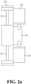
- Fig. 2a is a schematic view illustrating an arrangement of the tire bodies of the deformable tires according to the first embodiment of the present invention.
- Fig. 2a which is a side view of the deformable tire 1 according to the first embodiment of the present invention
- the tire bodies 15 are fixed on the core structure 13 via the spokes 11.
- the tire bodies 15 are arranged in two lines, which are parallel to and staggered with each other, around the core structure 13.
- each of the tire bodies 15 in the two lines of the tire bodies 15 are not in connection with each other, and the two lines of the tire bodies 15 are arranged so the tire bodies 15 are not overlapped with each other.
- Fig. 2b is a schematic view illustrating an arrangement of the tire bodies of the deformable tires according to another design. As shown in Fig. 2b , which is a side view illustrating the deformable tire 1 according to another design, it can be seen that the tire bodies 15 are fixed on the core structure 13 via the spokes 11. The tire bodies 15 are arranged in two lines, which are parallel to and staggered with each other, around the core structure 13.
- each of the tire bodies 15 in the two lines of the tire bodies 15 are not in connection with each other, and the two lines of the tire bodies 15 are arranged so the tire bodies 15 are overlapped with each other.
- the deformable tire 1 may have a higher stability.
- the tire bodies with overlapping arrangement and non-overlapping arrangement each has its own merits, and thus may be applied to various vehicles that are suitable for various types of ground surfaces.
- Fig. 3 is a schematic view illustrating the operation of the deformable tire according to the first embodiment of the present invention.
- the deformable tire 1 of the first embodiment of the present invention when the deformable tire 1 of the first embodiment of the present invention is near and about to climb a staircase 31, one of the spokes 11 will come into contact with the staircase 31 via the tire body 15 connected thereto. Due to its inherent elasticity, the spoke 11 in contact with the staircase 31 is dynamically adjusted to a second length D2 that is smaller than the first length D1. After one of the spokes 11 is compressed to the second length D2, it will stretch back to the first length D1 again by pushing against the staircase 31 via the elasticity thereof. In such a way, the deformable tire 1 may achieve climbing with the elasticity of the spokes 11.
- Fig. 4 is a schematic view illustrating the structure of a deformable tire according to a second embodiment of the present invention.
- the deformable tire 2 includes a plurality of spokes 11. A first end of each of the spokes 11 is connected to a core structure 13. A second end of each of the spokes 11 is connected to a tire body 15. A first length D1 is provided between each of the tire bodies 15 and the core structure 13.
- the spokes 11 are elastic.
- the core structure 13 is configured to fix and support the spokes 11, and each of the first lengths D1 is dynamically adjusted by the inherent elasticity of the spokes 11. Each of the first lengths D1 is adjusted by the inherent elasticity of each of the spokes 11.
- the structure of the tire body 15 is substantially similar to the tire bodies available on the market.
- each of the tire bodies 15 connected by the spokes 11 of the present invention are not in connection with each other and may be adjusted according to the type of the vehicle.
- the tire bodies 15 may be adjusted and changed into bicycle tires or wheelchair tires.
- the spokes 11 may be configured as other elastic structures.
- the structure of the deformable tire 2 of the second embodiment of the present invention is substantially similar to the structure of the deformable tire 1 of the first embodiment of the present invention.
- the operation of the deformable tire 2 is also the same as the deformable tire 1 in the first embodiment.
- the number of the spokes 11 shown in the figures is merely for illustration and may be adjusted according to the needs of the user or the vehicle.
- Fig. 5 is a schematic view illustrating the accommodation of the deformable tire according to another design.
- the deformable tire 2 according to this design is configured to accommodate via the holes 17. More particularly, the spokes 11 may move toward the core structure 13 via the holes 17 so as to adjust the first length D1 to a third length D3.
- the third length D3 is smaller than the first length D1.
- the spokes 11 are configured to penetrate into the core structure 13 through the holes 17.
- the overall size of the deformable tire 2 may be reduced, and the deformable tire 2 may be accommodated and carried more easily. It can be known from Figs.
- each of the spokes 11 may even wholly enter the holes 17 provided on the core structure 13 so as to minimize the size of the deformable tire 2.
- a deformable tire which is capable of climbing and is easy to be accommodated, is provided by the present invention.
- the deformable tire of the present invention is applicable to various types of vehicles, in particular, is applicable to bicycles and wheelchairs.
- a bicycle equipped with the deformable tire of the present invention may be able to freely climb various types of stairs.
- a wheelchair with the deformable tire of the present invention on its both sides may also be able to climb various types of stairs, so people with disabilities are enabled to climb stairs as well.
Landscapes
- Engineering & Computer Science (AREA)
- Mechanical Engineering (AREA)
- Tires In General (AREA)
- Handcart (AREA)
Description
- The present invention relates to a deformable tire, more particularly, relates to a tire with elastic spokes.
- A tire is a round object that can rotate around an axis thereof so as to decrease friction during movement. Once a tire is equipped with an axle, it is transformed into a primary component of various kinds of vehicles. Tires are one of the most important inventions in human history and are rather useful in the field of transportation. A conventional tire usually consists of a tire frame with spokes and a rubber tire body.
- In a conventional tire structure, a rubber tire body usually has a circular shape so as to be wrapped around a tire frame. Generally, a tire frame is formed with multiple spokes that are fixed on a core structure. Vehicles that are equipped with such conventional tires are meant to travel on flat surfaces. When it comes to ground with height differences such as a staircase, such conventional tires become ineffective. Since conventional tires are not designed for climbing, the vehicles equipped with such tires may experience inconvenience when travelling on ground with height differences. For example, small vehicles such as bicycles and wheelchairs equipped with conventional tires are likely to experience such inconvenience. In particular, wheelchair users, who are usually incapable of walking, may experience great trouble if the wheelchair is not capable of climbing.
- Based on the above reasons, there is an urgent need in the industry to develop a deformable tire based on elastic spokes, so vehicles equipped with such deformable tires are enabled to climb surfaces with height differences.
-
KR 2015 0102886 - In view of the foregoing drawbacks, a primary objective of the present invention is to provide a deformable tire including a plurality of spokes.
- The invention provides a deformable tire according to
claim 1. - Each of the first lengths is dynamically adjusted to a second length. Preferably, the second length is smaller than the first length.
- Other purposes, advantages and innovative features of the present invention will become apparent by reading the following detailed description together with the accompanying drawings.
- The present invention is best understood from the following detailed description when read in connection with the accompanying drawings. In order to achieve the foregoing objectives of the present invention, preferable embodiments of the present invention are illustrated in the drawings. It should be understood that the present invention should not be limited by the exact configuration, structure and apparatus illustrated in the drawings.
-
Fig. 1 is a schematic view illustrating the structure of a deformable tire according to a first embodiment of the present invention; -
Fig. 2a is a schematic view illustrating an arrangement of the tire bodies of the deformable tires according to the first embodiment of the present invention; -
Fig. 2b is a schematic view illustrating an arrangement of the tire bodies of the deformable tires according to another design; -
Fig. 3 is a schematic view illustrating the operation of the deformable tire according to the first embodiment of the present invention; -
Fig. 4 is a schematic view illustrating the structure of a deformable tire according to a second embodiment of the present invention; and -
Fig. 5 is a schematic view illustrating the accommodation of the deformable tire according to another design, which does not form part of the present invention. - The present invention will be described in detail with reference to the accompanying drawings in the following section. It should be noted that the drawings are not necessarily drawn to scale for the purpose of simplicity.
-
Fig. 1 is a schematic view illustrating the structure of a deformable tire according to a first embodiment of the present invention. As shown inFig. 1 , according to the first embodiment of the present invention, thedeformable tire 1 includes a plurality ofspokes 11. A first end of each of thespokes 11 is connected to acore structure 13. A second end of each of thespokes 11 is connected to atire body 15. A first length D1 is provided between each of thetire bodies 15 and thecore structure 13. Herein, thespokes 11 are elastic. Thecore structure 13 is configured to fix and support thespokes 11, and each of the first lengths D1 is dynamically adjusted by the elasticity of thespokes 11. It should be understood that the structure of thetire body 15 is substantially similar to the tire bodies available on the market. The difference between the two lies in that each of thetire bodies 15 connected by thespokes 11 of the present invention are not in connection with each other and may be adjusted according to the type of the vehicle. For example, thetire bodies 15 may be adjusted and changed into bicycle tires or wheelchair tires. In addition, in the present invention thespokes 11 are configured as elastic structures. Furthermore, the number of thespokes 11 shown in the figures is merely for the purpose of illustration and may be adjusted according to the needs of the user or the vehicle. -
Fig. 2a is a schematic view illustrating an arrangement of the tire bodies of the deformable tires according to the first embodiment of the present invention. As shown inFig. 2a , which is a side view of thedeformable tire 1 according to the first embodiment of the present invention, it can be seen that thetire bodies 15 are fixed on thecore structure 13 via thespokes 11. Thetire bodies 15 are arranged in two lines, which are parallel to and staggered with each other, around thecore structure 13. Herein, each of thetire bodies 15 in the two lines of thetire bodies 15 are not in connection with each other, and the two lines of thetire bodies 15 are arranged so thetire bodies 15 are not overlapped with each other. By arranging thetires bodies 15 in two staggered lines that are not overlapped with each other, thedeformable tire 1 may have a high climbing efficiency.Fig. 2b is a schematic view illustrating an arrangement of the tire bodies of the deformable tires according to another design. As shown inFig. 2b , which is a side view illustrating thedeformable tire 1 according to another design, it can be seen that thetire bodies 15 are fixed on thecore structure 13 via thespokes 11. Thetire bodies 15 are arranged in two lines, which are parallel to and staggered with each other, around thecore structure 13. Herein, each of thetire bodies 15 in the two lines of thetire bodies 15 are not in connection with each other, and the two lines of thetire bodies 15 are arranged so thetire bodies 15 are overlapped with each other. By arranging thetires bodies 15 in two staggered lines that are overlapped with each other, thedeformable tire 1 may have a higher stability. The tire bodies with overlapping arrangement and non-overlapping arrangement each has its own merits, and thus may be applied to various vehicles that are suitable for various types of ground surfaces. -
Fig. 3 is a schematic view illustrating the operation of the deformable tire according to the first embodiment of the present invention. As shown inFig. 3 , when thedeformable tire 1 of the first embodiment of the present invention is near and about to climb astaircase 31, one of thespokes 11 will come into contact with thestaircase 31 via thetire body 15 connected thereto. Due to its inherent elasticity, thespoke 11 in contact with thestaircase 31 is dynamically adjusted to a second length D2 that is smaller than the first length D1. After one of thespokes 11 is compressed to the second length D2, it will stretch back to the first length D1 again by pushing against thestaircase 31 via the elasticity thereof. In such a way, thedeformable tire 1 may achieve climbing with the elasticity of thespokes 11. -
Fig. 4 is a schematic view illustrating the structure of a deformable tire according to a second embodiment of the present invention. Referring toFig. 4 , thedeformable tire 2 includes a plurality ofspokes 11. A first end of each of thespokes 11 is connected to acore structure 13. A second end of each of thespokes 11 is connected to atire body 15. A first length D1 is provided between each of thetire bodies 15 and thecore structure 13. Herein, thespokes 11 are elastic. Thecore structure 13 is configured to fix and support thespokes 11, and each of the first lengths D1 is dynamically adjusted by the inherent elasticity of thespokes 11. Each of the first lengths D1 is adjusted by the inherent elasticity of each of thespokes 11. It should be understood that the structure of thetire body 15 is substantially similar to the tire bodies available on the market. The difference between the two lies in that each of thetire bodies 15 connected by thespokes 11 of the present invention are not in connection with each other and may be adjusted according to the type of the vehicle. For example, thetire bodies 15 may be adjusted and changed into bicycle tires or wheelchair tires. In addition, in the second embodiment of the present invention, thespokes 11 may be configured as other elastic structures. Based on the above description, it can be known that the structure of thedeformable tire 2 of the second embodiment of the present invention is substantially similar to the structure of thedeformable tire 1 of the first embodiment of the present invention. Hence, the operation of thedeformable tire 2 is also the same as thedeformable tire 1 in the first embodiment. Furthermore, the number of thespokes 11 shown in the figures is merely for illustration and may be adjusted according to the needs of the user or the vehicle. -
Fig. 5 is a schematic view illustrating the accommodation of the deformable tire according to another design. Referring toFig. 5 , thedeformable tire 2 according to this design is configured to accommodate via theholes 17. More particularly, thespokes 11 may move toward thecore structure 13 via theholes 17 so as to adjust the first length D1 to a third length D3. Herein, the third length D3 is smaller than the first length D1. In an accommodated state, thespokes 11 are configured to penetrate into thecore structure 13 through theholes 17. As a result, the overall size of thedeformable tire 2 may be reduced, and thedeformable tire 2 may be accommodated and carried more easily. It can be known fromFigs. 2a and2b that thespokes 11 and the tire bodies are arranged on thecore structure 13 in two parallel lines that are staggered with each other. Therefore, thespokes 11 are refrained from interfering with each other and also refrained from further affecting the accommodation process when being retracted toward the center of thecore structure 13. Moreover, the depths provided by theholes 17 for receiving thespokes 11 may be adjusted accordingly based on the needs of the users. In some other designs, each of thespokes 11 may even wholly enter theholes 17 provided on thecore structure 13 so as to minimize the size of thedeformable tire 2. - It can be known from the above description that a deformable tire, which is capable of climbing and is easy to be accommodated, is provided by the present invention. The deformable tire of the present invention is applicable to various types of vehicles, in particular, is applicable to bicycles and wheelchairs. A bicycle equipped with the deformable tire of the present invention may be able to freely climb various types of stairs. On the other hand, a wheelchair with the deformable tire of the present invention on its both sides may also be able to climb various types of stairs, so people with disabilities are enabled to climb stairs as well.
- Although the present invention has been described with reference to the preferred embodiments thereof, it is apparent to those skilled in the art that a variety of modifications and changes may be made without departing from the scope of the present invention which is intended to be defined by the appended claims.
Claims (2)
- A deformable tire (1), comprising:a plurality of spokes (11), wherein a first end of each of the spokes is connected to a core structure (13), and a second end of each of the spokes is connected to a tire body (15), wherein a first length (D1) is provided between each of the tire bodies and the core structure connected by each of the spokes;wherein the tire bodies (15) are fixed on the core structure (13) via the spokes (11) so that the tire bodies are movable in the direction towards the center of the core structure, and the tire bodies are arranged in two lines and are parallel to each other in an axial direction, and staggered in a circumferential direction; andwherein each of the tire bodies (15) in the two lines of the tire bodies are not in connection with each other, and the two lines of the tire bodies are arranged so the tire bodies are not overlapped with each other in a circumferential direction,characterised in that:the first end of each of the spokes (11) is immovable relative to the core structure (13),in that the spokes are made of an elastic material whereby the spokes have an elastic structure, andin that each of the first lengths (D1) between the first end of a spoke and the second end of a spoke is dynamically adjustable by way only of the elasticity of the spoke material.
- The deformable tire according to claim 1, wherein each of the first lengths (D1) is dynamically adjustable to a second length (D2), and the second length is smaller than the first length.
Applications Claiming Priority (1)
| Application Number | Priority Date | Filing Date | Title |
|---|---|---|---|
| PCT/CN2016/000276 WO2017201636A1 (en) | 2016-05-24 | 2016-05-24 | Deformable tire |
Publications (3)
| Publication Number | Publication Date |
|---|---|
| EP3466716A1 EP3466716A1 (en) | 2019-04-10 |
| EP3466716A4 EP3466716A4 (en) | 2020-01-08 |
| EP3466716B1 true EP3466716B1 (en) | 2025-03-19 |
Family
ID=60410975
Family Applications (1)
| Application Number | Title | Priority Date | Filing Date |
|---|---|---|---|
| EP16902626.7A Active EP3466716B1 (en) | 2016-05-24 | 2016-05-24 | Deformable tire |
Country Status (12)
| Country | Link |
|---|---|
| EP (1) | EP3466716B1 (en) |
| JP (1) | JP6871950B2 (en) |
| KR (1) | KR102301834B1 (en) |
| AU (1) | AU2016407855B2 (en) |
| BR (1) | BR112018072466B1 (en) |
| CA (1) | CA3022322C (en) |
| ES (1) | ES3033187T3 (en) |
| MX (1) | MX2018013600A (en) |
| PL (1) | PL3466716T3 (en) |
| RU (1) | RU2718505C1 (en) |
| WO (1) | WO2017201636A1 (en) |
| ZA (1) | ZA201807549B (en) |
Families Citing this family (7)
| Publication number | Priority date | Publication date | Assignee | Title |
|---|---|---|---|---|
| KR102154615B1 (en) * | 2018-12-07 | 2020-09-10 | 넥센타이어 주식회사 | Non-pneumatic cylinder tire |
| KR102327705B1 (en) * | 2020-02-17 | 2021-11-19 | 한국타이어앤테크놀로지 주식회사 | A non-pneumatic tire |
| IT202100000800A1 (en) * | 2021-01-18 | 2022-07-18 | Be Initia Srl | EQUIPMENT CAPABLE OF INDEPENDENTLY CLIMBING A FLAP OF STEPS |
| KR20220163785A (en) | 2021-06-03 | 2022-12-12 | 현대자동차주식회사 | Wheel and movable object including the same |
| KR20230160135A (en) | 2022-05-16 | 2023-11-23 | 현대자동차주식회사 | Wheel and mobility including the same |
| KR20230172335A (en) | 2022-06-15 | 2023-12-22 | 현대자동차주식회사 | Wheel structure and mobility including the same |
| KR20240045768A (en) | 2022-09-30 | 2024-04-08 | 현대자동차주식회사 | Wheel structure and method of controlling the same |
Citations (1)
| Publication number | Priority date | Publication date | Assignee | Title |
|---|---|---|---|---|
| KR20150102886A (en) * | 2015-07-10 | 2015-09-09 | 최현근 | structure for buffer wheel of two wheel vehicle |
Family Cites Families (18)
| Publication number | Priority date | Publication date | Assignee | Title |
|---|---|---|---|---|
| DE17678C (en) * | 1881-08-17 | 1882-03-30 | J. ROTTKAMP in Nippes b. Cöln | Innovations to springy wagon wheels |
| US669793A (en) * | 1900-12-13 | 1901-03-12 | William C Hillard | Spring vehicle-wheel. |
| DE273205C (en) * | 1913-06-05 | 1914-04-22 | Gilles Max | SUSPENSIVE WHEEL WITH SPOKE ATTACHED TO THE ELASTIC RIM |
| US1660845A (en) * | 1922-08-16 | 1928-02-28 | Mamessier Henri | Elastic wheel |
| US3590897A (en) * | 1969-10-21 | 1971-07-06 | Edwin C Bragdon | Spider wheel |
| US4108231A (en) * | 1976-10-06 | 1978-08-22 | Holchuk Leonard J | Vehicle wheel |
| JPH0365584U (en) * | 1989-10-31 | 1991-06-26 | ||
| RU2037431C1 (en) * | 1993-03-03 | 1995-06-19 | Магомет Салиханович Сагов | Method to increase roadability of vehicle wheel and design of wheel |
| JP3065584U (en) * | 1999-07-08 | 2000-02-02 | 陳文全 | Wheel |
| AU2001291482B2 (en) * | 2000-09-21 | 2005-06-09 | Innowheel Pty Ltd | Multiple directional wheel |
| CN2461792Y (en) * | 2000-12-27 | 2001-11-28 | 魏红军 | Folding leg wheel |
| JP3100128U (en) * | 2003-08-28 | 2004-04-30 | ▲せん▼増坤 | Wheel with shock absorbing structure |
| CN200945801Y (en) * | 2006-09-01 | 2007-09-12 | 周中理 | Explosion-proof vehicle wheel |
| CN200948729Y (en) * | 2006-09-01 | 2007-09-19 | 周中理 | Explosion-proof vehicle wheel |
| CN101462462A (en) * | 2007-12-19 | 2009-06-24 | 李上 | Elastic spoked wheel |
| KR20120070469A (en) * | 2010-12-21 | 2012-06-29 | 한국타이어 주식회사 | Non pneumatic tire |
| CN103963556A (en) * | 2014-04-30 | 2014-08-06 | 占舒婷 | Deformable wheel |
| KR20150102887A (en) * | 2015-07-22 | 2015-09-09 | 최현근 | structure for buffer wheel of two wheel vehicle |
-
2016
- 2016-05-24 CA CA3022322A patent/CA3022322C/en active Active
- 2016-05-24 BR BR112018072466-1A patent/BR112018072466B1/en active IP Right Grant
- 2016-05-24 ES ES16902626T patent/ES3033187T3/en active Active
- 2016-05-24 JP JP2018560679A patent/JP6871950B2/en active Active
- 2016-05-24 WO PCT/CN2016/000276 patent/WO2017201636A1/en not_active Ceased
- 2016-05-24 RU RU2018140125A patent/RU2718505C1/en active
- 2016-05-24 AU AU2016407855A patent/AU2016407855B2/en active Active
- 2016-05-24 KR KR1020187031644A patent/KR102301834B1/en active Active
- 2016-05-24 MX MX2018013600A patent/MX2018013600A/en unknown
- 2016-05-24 PL PL16902626.7T patent/PL3466716T3/en unknown
- 2016-05-24 EP EP16902626.7A patent/EP3466716B1/en active Active
-
2018
- 2018-11-09 ZA ZA2018/07549A patent/ZA201807549B/en unknown
Patent Citations (1)
| Publication number | Priority date | Publication date | Assignee | Title |
|---|---|---|---|---|
| KR20150102886A (en) * | 2015-07-10 | 2015-09-09 | 최현근 | structure for buffer wheel of two wheel vehicle |
Also Published As
| Publication number | Publication date |
|---|---|
| JP2019521027A (en) | 2019-07-25 |
| BR112018072466B1 (en) | 2021-06-22 |
| CA3022322A1 (en) | 2017-11-30 |
| JP6871950B2 (en) | 2021-05-19 |
| EP3466716A4 (en) | 2020-01-08 |
| RU2718505C1 (en) | 2020-04-08 |
| MX2018013600A (en) | 2019-02-21 |
| ES3033187T3 (en) | 2025-07-31 |
| EP3466716A1 (en) | 2019-04-10 |
| CA3022322C (en) | 2021-03-16 |
| WO2017201636A1 (en) | 2017-11-30 |
| AU2016407855B2 (en) | 2020-02-20 |
| PL3466716T3 (en) | 2025-08-18 |
| AU2016407855A1 (en) | 2018-11-15 |
| KR102301834B1 (en) | 2021-09-14 |
| BR112018072466A2 (en) | 2019-02-19 |
| ZA201807549B (en) | 2020-02-26 |
| KR20180126576A (en) | 2018-11-27 |
Similar Documents
| Publication | Publication Date | Title |
|---|---|---|
| US10023004B2 (en) | Deformable tire | |
| AU2016407855B2 (en) | Deformable tire | |
| US8011736B2 (en) | Collapsible wheel | |
| CN107415574B (en) | deformed tire | |
| TWI632075B (en) | Deformable tire | |
| CN102555674B (en) | Non pneumatic tire | |
| EP3135498B1 (en) | Kayak trolley | |
| US9527344B1 (en) | Terrain resilient wheel maintaining a uniform elevation | |
| TW200420447A (en) | Bicycle rim | |
| US10532611B2 (en) | Tire and wheel assembly having angled interfaces | |
| US20120274037A1 (en) | Compressible wheel tip for a walking aid | |
| US9434208B2 (en) | Omnidirectional wheel | |
| US10814670B2 (en) | Low-speed vehicle wheel assembly | |
| JP6380934B2 (en) | Wheelchair mobility aid with built-in wheelchair | |
| EP2479042B1 (en) | Tire rim | |
| KR101767322B1 (en) | Carry aid device for heavy duty tires | |
| KR101659042B1 (en) | Tracked moving apparatus | |
| CN118182016A (en) | Spoke assembly of non-pneumatic tire and vehicle | |
| US942741A (en) | Cushion-wheel. | |
| HK1208206B (en) | Omnidirectional wheel | |
| RU2015108211A (en) | VEHICLE TO overcome obstacles |
Legal Events
| Date | Code | Title | Description |
|---|---|---|---|
| STAA | Information on the status of an ep patent application or granted ep patent |
Free format text: STATUS: THE INTERNATIONAL PUBLICATION HAS BEEN MADE |
|
| PUAI | Public reference made under article 153(3) epc to a published international application that has entered the european phase |
Free format text: ORIGINAL CODE: 0009012 |
|
| STAA | Information on the status of an ep patent application or granted ep patent |
Free format text: STATUS: REQUEST FOR EXAMINATION WAS MADE |
|
| 17P | Request for examination filed |
Effective date: 20181023 |
|
| AK | Designated contracting states |
Kind code of ref document: A1 Designated state(s): AL AT BE BG CH CY CZ DE DK EE ES FI FR GB GR HR HU IE IS IT LI LT LU LV MC MK MT NL NO PL PT RO RS SE SI SK SM TR |
|
| AX | Request for extension of the european patent |
Extension state: BA ME |
|
| DAV | Request for validation of the european patent (deleted) | ||
| DAX | Request for extension of the european patent (deleted) | ||
| A4 | Supplementary search report drawn up and despatched |
Effective date: 20191211 |
|
| RIC1 | Information provided on ipc code assigned before grant |
Ipc: B60B 25/02 20060101ALI20191205BHEP Ipc: B60B 1/04 20060101ALI20191205BHEP Ipc: B60B 9/28 20060101AFI20191205BHEP Ipc: B60B 1/06 20060101ALN20191205BHEP |
|
| STAA | Information on the status of an ep patent application or granted ep patent |
Free format text: STATUS: EXAMINATION IS IN PROGRESS |
|
| 17Q | First examination report despatched |
Effective date: 20220712 |
|
| GRAP | Despatch of communication of intention to grant a patent |
Free format text: ORIGINAL CODE: EPIDOSNIGR1 |
|
| STAA | Information on the status of an ep patent application or granted ep patent |
Free format text: STATUS: GRANT OF PATENT IS INTENDED |
|
| RIC1 | Information provided on ipc code assigned before grant |
Ipc: B60B 1/06 20060101ALN20241120BHEP Ipc: B60B 25/02 20060101ALI20241120BHEP Ipc: B60B 1/04 20060101ALI20241120BHEP Ipc: B60B 9/28 20060101AFI20241120BHEP |
|
| INTG | Intention to grant announced |
Effective date: 20241128 |
|
| GRAS | Grant fee paid |
Free format text: ORIGINAL CODE: EPIDOSNIGR3 |
|
| GRAA | (expected) grant |
Free format text: ORIGINAL CODE: 0009210 |
|
| STAA | Information on the status of an ep patent application or granted ep patent |
Free format text: STATUS: THE PATENT HAS BEEN GRANTED |
|
| AK | Designated contracting states |
Kind code of ref document: B1 Designated state(s): AL AT BE BG CH CY CZ DE DK EE ES FI FR GB GR HR HU IE IS IT LI LT LU LV MC MK MT NL NO PL PT RO RS SE SI SK SM TR |
|
| P01 | Opt-out of the competence of the unified patent court (upc) registered |
Free format text: CASE NUMBER: APP_7004/2025 Effective date: 20250211 |
|
| REG | Reference to a national code |
Ref country code: GB Ref legal event code: FG4D |
|
| REG | Reference to a national code |
Ref country code: CH Ref legal event code: EP |
|
| REG | Reference to a national code |
Ref country code: IE Ref legal event code: FG4D |
|
| REG | Reference to a national code |
Ref country code: DE Ref legal event code: R096 Ref document number: 602016091637 Country of ref document: DE |
|
| PG25 | Lapsed in a contracting state [announced via postgrant information from national office to epo] |
Ref country code: RS Free format text: LAPSE BECAUSE OF FAILURE TO SUBMIT A TRANSLATION OF THE DESCRIPTION OR TO PAY THE FEE WITHIN THE PRESCRIBED TIME-LIMIT Effective date: 20250619 |
|
| PG25 | Lapsed in a contracting state [announced via postgrant information from national office to epo] |
Ref country code: FI Free format text: LAPSE BECAUSE OF FAILURE TO SUBMIT A TRANSLATION OF THE DESCRIPTION OR TO PAY THE FEE WITHIN THE PRESCRIBED TIME-LIMIT Effective date: 20250319 |
|
| PGFP | Annual fee paid to national office [announced via postgrant information from national office to epo] |
Ref country code: DE Payment date: 20250605 Year of fee payment: 10 |
|
| REG | Reference to a national code |
Ref country code: NL Ref legal event code: FP |
|
| PGFP | Annual fee paid to national office [announced via postgrant information from national office to epo] |
Ref country code: ES Payment date: 20250618 Year of fee payment: 10 Ref country code: GB Payment date: 20250604 Year of fee payment: 10 |
|
| REG | Reference to a national code |
Ref country code: LT Ref legal event code: MG9D |
|
| PG25 | Lapsed in a contracting state [announced via postgrant information from national office to epo] |
Ref country code: NO Free format text: LAPSE BECAUSE OF FAILURE TO SUBMIT A TRANSLATION OF THE DESCRIPTION OR TO PAY THE FEE WITHIN THE PRESCRIBED TIME-LIMIT Effective date: 20250619 |
|
| PGFP | Annual fee paid to national office [announced via postgrant information from national office to epo] |
Ref country code: NL Payment date: 20250627 Year of fee payment: 10 |
|
| PG25 | Lapsed in a contracting state [announced via postgrant information from national office to epo] |
Ref country code: HR Free format text: LAPSE BECAUSE OF FAILURE TO SUBMIT A TRANSLATION OF THE DESCRIPTION OR TO PAY THE FEE WITHIN THE PRESCRIBED TIME-LIMIT Effective date: 20250319 |
|
| PG25 | Lapsed in a contracting state [announced via postgrant information from national office to epo] |
Ref country code: LV Free format text: LAPSE BECAUSE OF FAILURE TO SUBMIT A TRANSLATION OF THE DESCRIPTION OR TO PAY THE FEE WITHIN THE PRESCRIBED TIME-LIMIT Effective date: 20250319 |
|
| PGFP | Annual fee paid to national office [announced via postgrant information from national office to epo] |
Ref country code: FR Payment date: 20250606 Year of fee payment: 10 |
|
| PG25 | Lapsed in a contracting state [announced via postgrant information from national office to epo] |
Ref country code: GR Free format text: LAPSE BECAUSE OF FAILURE TO SUBMIT A TRANSLATION OF THE DESCRIPTION OR TO PAY THE FEE WITHIN THE PRESCRIBED TIME-LIMIT Effective date: 20250620 Ref country code: BG Free format text: LAPSE BECAUSE OF FAILURE TO SUBMIT A TRANSLATION OF THE DESCRIPTION OR TO PAY THE FEE WITHIN THE PRESCRIBED TIME-LIMIT Effective date: 20250319 |
|
| PGFP | Annual fee paid to national office [announced via postgrant information from national office to epo] |
Ref country code: CH Payment date: 20250613 Year of fee payment: 10 |
|
| PGFP | Annual fee paid to national office [announced via postgrant information from national office to epo] |
Ref country code: TR Payment date: 20250610 Year of fee payment: 10 |
|
| REG | Reference to a national code |
Ref country code: ES Ref legal event code: FG2A Ref document number: 3033187 Country of ref document: ES Kind code of ref document: T3 Effective date: 20250731 |
|
| REG | Reference to a national code |
Ref country code: AT Ref legal event code: MK05 Ref document number: 1776681 Country of ref document: AT Kind code of ref document: T Effective date: 20250319 |
|
| PG25 | Lapsed in a contracting state [announced via postgrant information from national office to epo] |
Ref country code: SE Free format text: LAPSE BECAUSE OF FAILURE TO SUBMIT A TRANSLATION OF THE DESCRIPTION OR TO PAY THE FEE WITHIN THE PRESCRIBED TIME-LIMIT Effective date: 20250319 |
|
| PG25 | Lapsed in a contracting state [announced via postgrant information from national office to epo] |
Ref country code: SM Free format text: LAPSE BECAUSE OF FAILURE TO SUBMIT A TRANSLATION OF THE DESCRIPTION OR TO PAY THE FEE WITHIN THE PRESCRIBED TIME-LIMIT Effective date: 20250319 |
|
| PG25 | Lapsed in a contracting state [announced via postgrant information from national office to epo] |
Ref country code: PT Free format text: LAPSE BECAUSE OF FAILURE TO SUBMIT A TRANSLATION OF THE DESCRIPTION OR TO PAY THE FEE WITHIN THE PRESCRIBED TIME-LIMIT Effective date: 20250721 |
|
| PGFP | Annual fee paid to national office [announced via postgrant information from national office to epo] |
Ref country code: PL Payment date: 20250610 Year of fee payment: 10 Ref country code: IT Payment date: 20250618 Year of fee payment: 10 |
|
| PG25 | Lapsed in a contracting state [announced via postgrant information from national office to epo] |
Ref country code: AT Free format text: LAPSE BECAUSE OF FAILURE TO SUBMIT A TRANSLATION OF THE DESCRIPTION OR TO PAY THE FEE WITHIN THE PRESCRIBED TIME-LIMIT Effective date: 20250319 |
|
| PG25 | Lapsed in a contracting state [announced via postgrant information from national office to epo] |
Ref country code: CZ Free format text: LAPSE BECAUSE OF FAILURE TO SUBMIT A TRANSLATION OF THE DESCRIPTION OR TO PAY THE FEE WITHIN THE PRESCRIBED TIME-LIMIT Effective date: 20250319 Ref country code: EE Free format text: LAPSE BECAUSE OF FAILURE TO SUBMIT A TRANSLATION OF THE DESCRIPTION OR TO PAY THE FEE WITHIN THE PRESCRIBED TIME-LIMIT Effective date: 20250319 |
|
| PG25 | Lapsed in a contracting state [announced via postgrant information from national office to epo] |
Ref country code: RO Free format text: LAPSE BECAUSE OF FAILURE TO SUBMIT A TRANSLATION OF THE DESCRIPTION OR TO PAY THE FEE WITHIN THE PRESCRIBED TIME-LIMIT Effective date: 20250319 |
|
| PG25 | Lapsed in a contracting state [announced via postgrant information from national office to epo] |
Ref country code: SK Free format text: LAPSE BECAUSE OF FAILURE TO SUBMIT A TRANSLATION OF THE DESCRIPTION OR TO PAY THE FEE WITHIN THE PRESCRIBED TIME-LIMIT Effective date: 20250319 |
|
| PG25 | Lapsed in a contracting state [announced via postgrant information from national office to epo] |
Ref country code: IS Free format text: LAPSE BECAUSE OF FAILURE TO SUBMIT A TRANSLATION OF THE DESCRIPTION OR TO PAY THE FEE WITHIN THE PRESCRIBED TIME-LIMIT Effective date: 20250719 |
|
| REG | Reference to a national code |
Ref country code: DE Ref legal event code: R097 Ref document number: 602016091637 Country of ref document: DE |
|
| PG25 | Lapsed in a contracting state [announced via postgrant information from national office to epo] |
Ref country code: DK Free format text: LAPSE BECAUSE OF FAILURE TO SUBMIT A TRANSLATION OF THE DESCRIPTION OR TO PAY THE FEE WITHIN THE PRESCRIBED TIME-LIMIT Effective date: 20250319 |
|
| PG25 | Lapsed in a contracting state [announced via postgrant information from national office to epo] |
Ref country code: LU Free format text: LAPSE BECAUSE OF NON-PAYMENT OF DUE FEES Effective date: 20250524 |
|
| PLBE | No opposition filed within time limit |
Free format text: ORIGINAL CODE: 0009261 |
|
| STAA | Information on the status of an ep patent application or granted ep patent |
Free format text: STATUS: NO OPPOSITION FILED WITHIN TIME LIMIT |
|
| REG | Reference to a national code |
Ref country code: CH Ref legal event code: L10 Free format text: ST27 STATUS EVENT CODE: U-0-0-L10-L00 (AS PROVIDED BY THE NATIONAL OFFICE) Effective date: 20260128 |
|
| REG | Reference to a national code |
Ref country code: BE Ref legal event code: MM Effective date: 20250531 |
|
| PG25 | Lapsed in a contracting state [announced via postgrant information from national office to epo] |
Ref country code: MC Free format text: LAPSE BECAUSE OF FAILURE TO SUBMIT A TRANSLATION OF THE DESCRIPTION OR TO PAY THE FEE WITHIN THE PRESCRIBED TIME-LIMIT Effective date: 20250319 |
|
| 26N | No opposition filed |
Effective date: 20251222 |
|
| PG25 | Lapsed in a contracting state [announced via postgrant information from national office to epo] |
Ref country code: IE Free format text: LAPSE BECAUSE OF NON-PAYMENT OF DUE FEES Effective date: 20250524 |
|
| PG25 | Lapsed in a contracting state [announced via postgrant information from national office to epo] |
Ref country code: BE Free format text: LAPSE BECAUSE OF NON-PAYMENT OF DUE FEES Effective date: 20250531 |