EP3466686A1 - Additive manufacturing fiber composites and related systems and methods - Google Patents
Additive manufacturing fiber composites and related systems and methods Download PDFInfo
- Publication number
- EP3466686A1 EP3466686A1 EP18183823.6A EP18183823A EP3466686A1 EP 3466686 A1 EP3466686 A1 EP 3466686A1 EP 18183823 A EP18183823 A EP 18183823A EP 3466686 A1 EP3466686 A1 EP 3466686A1
- Authority
- EP
- European Patent Office
- Prior art keywords
- energy
- emissive dopant
- additive manufacturing
- matrix material
- activating
- Prior art date
- Legal status (The legal status is an assumption and is not a legal conclusion. Google has not performed a legal analysis and makes no representation as to the accuracy of the status listed.)
- Granted
Links
- 239000000835 fiber Substances 0.000 title claims abstract description 165
- 238000004519 manufacturing process Methods 0.000 title claims abstract description 149
- 239000000654 additive Substances 0.000 title claims abstract description 136
- 230000000996 additive effect Effects 0.000 title claims abstract description 136
- 239000002131 composite material Substances 0.000 title claims abstract description 73
- 238000000034 method Methods 0.000 title claims abstract description 51
- 239000002019 doping agent Substances 0.000 claims abstract description 186
- 239000011159 matrix material Substances 0.000 claims abstract description 146
- 230000003213 activating effect Effects 0.000 claims abstract description 130
- 230000000694 effects Effects 0.000 claims abstract description 16
- 230000004044 response Effects 0.000 claims abstract description 14
- 239000011347 resin Substances 0.000 claims description 17
- 229920005989 resin Polymers 0.000 claims description 17
- 239000002105 nanoparticle Substances 0.000 claims description 13
- 230000000149 penetrating effect Effects 0.000 claims description 9
- 230000005855 radiation Effects 0.000 claims description 9
- 239000000203 mixture Substances 0.000 claims description 6
- 230000005865 ionizing radiation Effects 0.000 claims description 3
- 238000009826 distribution Methods 0.000 description 14
- 239000000463 material Substances 0.000 description 11
- 230000006870 function Effects 0.000 description 8
- 229920000642 polymer Polymers 0.000 description 5
- 230000002688 persistence Effects 0.000 description 4
- 229920000049 Carbon (fiber) Polymers 0.000 description 3
- 239000004917 carbon fiber Substances 0.000 description 3
- 239000002245 particle Substances 0.000 description 3
- 230000037361 pathway Effects 0.000 description 3
- 239000007787 solid Substances 0.000 description 3
- 230000007704 transition Effects 0.000 description 3
- 229910004829 CaWO4 Inorganic materials 0.000 description 2
- 230000005540 biological transmission Effects 0.000 description 2
- 238000010894 electron beam technology Methods 0.000 description 2
- 230000005284 excitation Effects 0.000 description 2
- 230000009969 flowable effect Effects 0.000 description 2
- 239000012783 reinforcing fiber Substances 0.000 description 2
- ZOXJGFHDIHLPTG-UHFFFAOYSA-N Boron Chemical compound [B] ZOXJGFHDIHLPTG-UHFFFAOYSA-N 0.000 description 1
- 229910003016 Lu2SiO5 Inorganic materials 0.000 description 1
- 230000004913 activation Effects 0.000 description 1
- 229910052782 aluminium Inorganic materials 0.000 description 1
- XAGFODPZIPBFFR-UHFFFAOYSA-N aluminium Chemical compound [Al] XAGFODPZIPBFFR-UHFFFAOYSA-N 0.000 description 1
- 239000004760 aramid Substances 0.000 description 1
- 229920006231 aramid fiber Polymers 0.000 description 1
- 229910001632 barium fluoride Inorganic materials 0.000 description 1
- 229910052796 boron Inorganic materials 0.000 description 1
- 239000003054 catalyst Substances 0.000 description 1
- 239000000919 ceramic Substances 0.000 description 1
- 239000011258 core-shell material Substances 0.000 description 1
- 238000004132 cross linking Methods 0.000 description 1
- 238000010586 diagram Methods 0.000 description 1
- 230000005684 electric field Effects 0.000 description 1
- 230000001815 facial effect Effects 0.000 description 1
- 239000003365 glass fiber Substances 0.000 description 1
- 230000001678 irradiating effect Effects 0.000 description 1
- 239000007788 liquid Substances 0.000 description 1
- 239000007791 liquid phase Substances 0.000 description 1
- 229910052751 metal Inorganic materials 0.000 description 1
- 239000002184 metal Substances 0.000 description 1
- 239000002086 nanomaterial Substances 0.000 description 1
- 229940031182 nanoparticles iron oxide Drugs 0.000 description 1
- 239000002073 nanorod Substances 0.000 description 1
- 239000013307 optical fiber Substances 0.000 description 1
- 230000008569 process Effects 0.000 description 1
- HBMJWWWQQXIZIP-UHFFFAOYSA-N silicon carbide Chemical compound [Si+]#[C-] HBMJWWWQQXIZIP-UHFFFAOYSA-N 0.000 description 1
- 229910010271 silicon carbide Inorganic materials 0.000 description 1
- 229920001187 thermosetting polymer Polymers 0.000 description 1
- 238000009827 uniform distribution Methods 0.000 description 1
Images


Classifications
-
- B—PERFORMING OPERATIONS; TRANSPORTING
- B29—WORKING OF PLASTICS; WORKING OF SUBSTANCES IN A PLASTIC STATE IN GENERAL
- B29C—SHAPING OR JOINING OF PLASTICS; SHAPING OF MATERIAL IN A PLASTIC STATE, NOT OTHERWISE PROVIDED FOR; AFTER-TREATMENT OF THE SHAPED PRODUCTS, e.g. REPAIRING
- B29C64/00—Additive manufacturing, i.e. manufacturing of three-dimensional [3D] objects by additive deposition, additive agglomeration or additive layering, e.g. by 3D printing, stereolithography or selective laser sintering
- B29C64/20—Apparatus for additive manufacturing; Details thereof or accessories therefor
- B29C64/264—Arrangements for irradiation
- B29C64/291—Arrangements for irradiation for operating globally, e.g. together with selectively applied activators or inhibitors
-
- B—PERFORMING OPERATIONS; TRANSPORTING
- B29—WORKING OF PLASTICS; WORKING OF SUBSTANCES IN A PLASTIC STATE IN GENERAL
- B29C—SHAPING OR JOINING OF PLASTICS; SHAPING OF MATERIAL IN A PLASTIC STATE, NOT OTHERWISE PROVIDED FOR; AFTER-TREATMENT OF THE SHAPED PRODUCTS, e.g. REPAIRING
- B29C64/00—Additive manufacturing, i.e. manufacturing of three-dimensional [3D] objects by additive deposition, additive agglomeration or additive layering, e.g. by 3D printing, stereolithography or selective laser sintering
- B29C64/20—Apparatus for additive manufacturing; Details thereof or accessories therefor
-
- B—PERFORMING OPERATIONS; TRANSPORTING
- B29—WORKING OF PLASTICS; WORKING OF SUBSTANCES IN A PLASTIC STATE IN GENERAL
- B29C—SHAPING OR JOINING OF PLASTICS; SHAPING OF MATERIAL IN A PLASTIC STATE, NOT OTHERWISE PROVIDED FOR; AFTER-TREATMENT OF THE SHAPED PRODUCTS, e.g. REPAIRING
- B29C35/00—Heating, cooling or curing, e.g. crosslinking or vulcanising; Apparatus therefor
- B29C35/02—Heating or curing, e.g. crosslinking or vulcanizing during moulding, e.g. in a mould
- B29C35/08—Heating or curing, e.g. crosslinking or vulcanizing during moulding, e.g. in a mould by wave energy or particle radiation
- B29C35/0805—Heating or curing, e.g. crosslinking or vulcanizing during moulding, e.g. in a mould by wave energy or particle radiation using electromagnetic radiation
-
- B—PERFORMING OPERATIONS; TRANSPORTING
- B29—WORKING OF PLASTICS; WORKING OF SUBSTANCES IN A PLASTIC STATE IN GENERAL
- B29C—SHAPING OR JOINING OF PLASTICS; SHAPING OF MATERIAL IN A PLASTIC STATE, NOT OTHERWISE PROVIDED FOR; AFTER-TREATMENT OF THE SHAPED PRODUCTS, e.g. REPAIRING
- B29C64/00—Additive manufacturing, i.e. manufacturing of three-dimensional [3D] objects by additive deposition, additive agglomeration or additive layering, e.g. by 3D printing, stereolithography or selective laser sintering
- B29C64/10—Processes of additive manufacturing
- B29C64/106—Processes of additive manufacturing using only liquids or viscous materials, e.g. depositing a continuous bead of viscous material
- B29C64/118—Processes of additive manufacturing using only liquids or viscous materials, e.g. depositing a continuous bead of viscous material using filamentary material being melted, e.g. fused deposition modelling [FDM]
-
- B—PERFORMING OPERATIONS; TRANSPORTING
- B29—WORKING OF PLASTICS; WORKING OF SUBSTANCES IN A PLASTIC STATE IN GENERAL
- B29C—SHAPING OR JOINING OF PLASTICS; SHAPING OF MATERIAL IN A PLASTIC STATE, NOT OTHERWISE PROVIDED FOR; AFTER-TREATMENT OF THE SHAPED PRODUCTS, e.g. REPAIRING
- B29C64/00—Additive manufacturing, i.e. manufacturing of three-dimensional [3D] objects by additive deposition, additive agglomeration or additive layering, e.g. by 3D printing, stereolithography or selective laser sintering
- B29C64/10—Processes of additive manufacturing
- B29C64/106—Processes of additive manufacturing using only liquids or viscous materials, e.g. depositing a continuous bead of viscous material
- B29C64/124—Processes of additive manufacturing using only liquids or viscous materials, e.g. depositing a continuous bead of viscous material using layers of liquid which are selectively solidified
- B29C64/129—Processes of additive manufacturing using only liquids or viscous materials, e.g. depositing a continuous bead of viscous material using layers of liquid which are selectively solidified characterised by the energy source therefor, e.g. by global irradiation combined with a mask
-
- B—PERFORMING OPERATIONS; TRANSPORTING
- B33—ADDITIVE MANUFACTURING TECHNOLOGY
- B33Y—ADDITIVE MANUFACTURING, i.e. MANUFACTURING OF THREE-DIMENSIONAL [3-D] OBJECTS BY ADDITIVE DEPOSITION, ADDITIVE AGGLOMERATION OR ADDITIVE LAYERING, e.g. BY 3-D PRINTING, STEREOLITHOGRAPHY OR SELECTIVE LASER SINTERING
- B33Y10/00—Processes of additive manufacturing
-
- B—PERFORMING OPERATIONS; TRANSPORTING
- B33—ADDITIVE MANUFACTURING TECHNOLOGY
- B33Y—ADDITIVE MANUFACTURING, i.e. MANUFACTURING OF THREE-DIMENSIONAL [3-D] OBJECTS BY ADDITIVE DEPOSITION, ADDITIVE AGGLOMERATION OR ADDITIVE LAYERING, e.g. BY 3-D PRINTING, STEREOLITHOGRAPHY OR SELECTIVE LASER SINTERING
- B33Y70/00—Materials specially adapted for additive manufacturing
- B33Y70/10—Composites of different types of material, e.g. mixtures of ceramics and polymers or mixtures of metals and biomaterials
-
- G—PHYSICS
- G01—MEASURING; TESTING
- G01T—MEASUREMENT OF NUCLEAR OR X-RADIATION
- G01T1/00—Measuring X-radiation, gamma radiation, corpuscular radiation, or cosmic radiation
-
- B—PERFORMING OPERATIONS; TRANSPORTING
- B29—WORKING OF PLASTICS; WORKING OF SUBSTANCES IN A PLASTIC STATE IN GENERAL
- B29B—PREPARATION OR PRETREATMENT OF THE MATERIAL TO BE SHAPED; MAKING GRANULES OR PREFORMS; RECOVERY OF PLASTICS OR OTHER CONSTITUENTS OF WASTE MATERIAL CONTAINING PLASTICS
- B29B15/00—Pretreatment of the material to be shaped, not covered by groups B29B7/00 - B29B13/00
- B29B15/08—Pretreatment of the material to be shaped, not covered by groups B29B7/00 - B29B13/00 of reinforcements or fillers
- B29B15/10—Coating or impregnating independently of the moulding or shaping step
- B29B15/12—Coating or impregnating independently of the moulding or shaping step of reinforcements of indefinite length
- B29B15/122—Coating or impregnating independently of the moulding or shaping step of reinforcements of indefinite length with a matrix in liquid form, e.g. as melt, solution or latex
-
- B—PERFORMING OPERATIONS; TRANSPORTING
- B29—WORKING OF PLASTICS; WORKING OF SUBSTANCES IN A PLASTIC STATE IN GENERAL
- B29B—PREPARATION OR PRETREATMENT OF THE MATERIAL TO BE SHAPED; MAKING GRANULES OR PREFORMS; RECOVERY OF PLASTICS OR OTHER CONSTITUENTS OF WASTE MATERIAL CONTAINING PLASTICS
- B29B15/00—Pretreatment of the material to be shaped, not covered by groups B29B7/00 - B29B13/00
- B29B15/08—Pretreatment of the material to be shaped, not covered by groups B29B7/00 - B29B13/00 of reinforcements or fillers
- B29B15/10—Coating or impregnating independently of the moulding or shaping step
- B29B15/12—Coating or impregnating independently of the moulding or shaping step of reinforcements of indefinite length
- B29B15/14—Coating or impregnating independently of the moulding or shaping step of reinforcements of indefinite length of filaments or wires
-
- B—PERFORMING OPERATIONS; TRANSPORTING
- B29—WORKING OF PLASTICS; WORKING OF SUBSTANCES IN A PLASTIC STATE IN GENERAL
- B29C—SHAPING OR JOINING OF PLASTICS; SHAPING OF MATERIAL IN A PLASTIC STATE, NOT OTHERWISE PROVIDED FOR; AFTER-TREATMENT OF THE SHAPED PRODUCTS, e.g. REPAIRING
- B29C35/00—Heating, cooling or curing, e.g. crosslinking or vulcanising; Apparatus therefor
- B29C35/02—Heating or curing, e.g. crosslinking or vulcanizing during moulding, e.g. in a mould
- B29C35/08—Heating or curing, e.g. crosslinking or vulcanizing during moulding, e.g. in a mould by wave energy or particle radiation
- B29C35/0805—Heating or curing, e.g. crosslinking or vulcanizing during moulding, e.g. in a mould by wave energy or particle radiation using electromagnetic radiation
- B29C2035/0844—Heating or curing, e.g. crosslinking or vulcanizing during moulding, e.g. in a mould by wave energy or particle radiation using electromagnetic radiation using X-ray
-
- B—PERFORMING OPERATIONS; TRANSPORTING
- B29—WORKING OF PLASTICS; WORKING OF SUBSTANCES IN A PLASTIC STATE IN GENERAL
- B29C—SHAPING OR JOINING OF PLASTICS; SHAPING OF MATERIAL IN A PLASTIC STATE, NOT OTHERWISE PROVIDED FOR; AFTER-TREATMENT OF THE SHAPED PRODUCTS, e.g. REPAIRING
- B29C35/00—Heating, cooling or curing, e.g. crosslinking or vulcanising; Apparatus therefor
- B29C35/02—Heating or curing, e.g. crosslinking or vulcanizing during moulding, e.g. in a mould
- B29C35/08—Heating or curing, e.g. crosslinking or vulcanizing during moulding, e.g. in a mould by wave energy or particle radiation
- B29C35/0805—Heating or curing, e.g. crosslinking or vulcanizing during moulding, e.g. in a mould by wave energy or particle radiation using electromagnetic radiation
- B29C2035/085—Heating or curing, e.g. crosslinking or vulcanizing during moulding, e.g. in a mould by wave energy or particle radiation using electromagnetic radiation using gamma-ray
-
- B—PERFORMING OPERATIONS; TRANSPORTING
- B29—WORKING OF PLASTICS; WORKING OF SUBSTANCES IN A PLASTIC STATE IN GENERAL
- B29C—SHAPING OR JOINING OF PLASTICS; SHAPING OF MATERIAL IN A PLASTIC STATE, NOT OTHERWISE PROVIDED FOR; AFTER-TREATMENT OF THE SHAPED PRODUCTS, e.g. REPAIRING
- B29C64/00—Additive manufacturing, i.e. manufacturing of three-dimensional [3D] objects by additive deposition, additive agglomeration or additive layering, e.g. by 3D printing, stereolithography or selective laser sintering
- B29C64/10—Processes of additive manufacturing
- B29C64/165—Processes of additive manufacturing using a combination of solid and fluid materials, e.g. a powder selectively bound by a liquid binder, catalyst, inhibitor or energy absorber
-
- B—PERFORMING OPERATIONS; TRANSPORTING
- B29—WORKING OF PLASTICS; WORKING OF SUBSTANCES IN A PLASTIC STATE IN GENERAL
- B29C—SHAPING OR JOINING OF PLASTICS; SHAPING OF MATERIAL IN A PLASTIC STATE, NOT OTHERWISE PROVIDED FOR; AFTER-TREATMENT OF THE SHAPED PRODUCTS, e.g. REPAIRING
- B29C64/00—Additive manufacturing, i.e. manufacturing of three-dimensional [3D] objects by additive deposition, additive agglomeration or additive layering, e.g. by 3D printing, stereolithography or selective laser sintering
- B29C64/10—Processes of additive manufacturing
- B29C64/188—Processes of additive manufacturing involving additional operations performed on the added layers, e.g. smoothing, grinding or thickness control
-
- B—PERFORMING OPERATIONS; TRANSPORTING
- B29—WORKING OF PLASTICS; WORKING OF SUBSTANCES IN A PLASTIC STATE IN GENERAL
- B29C—SHAPING OR JOINING OF PLASTICS; SHAPING OF MATERIAL IN A PLASTIC STATE, NOT OTHERWISE PROVIDED FOR; AFTER-TREATMENT OF THE SHAPED PRODUCTS, e.g. REPAIRING
- B29C64/00—Additive manufacturing, i.e. manufacturing of three-dimensional [3D] objects by additive deposition, additive agglomeration or additive layering, e.g. by 3D printing, stereolithography or selective laser sintering
- B29C64/20—Apparatus for additive manufacturing; Details thereof or accessories therefor
- B29C64/205—Means for applying layers
- B29C64/209—Heads; Nozzles
-
- B—PERFORMING OPERATIONS; TRANSPORTING
- B29—WORKING OF PLASTICS; WORKING OF SUBSTANCES IN A PLASTIC STATE IN GENERAL
- B29C—SHAPING OR JOINING OF PLASTICS; SHAPING OF MATERIAL IN A PLASTIC STATE, NOT OTHERWISE PROVIDED FOR; AFTER-TREATMENT OF THE SHAPED PRODUCTS, e.g. REPAIRING
- B29C64/00—Additive manufacturing, i.e. manufacturing of three-dimensional [3D] objects by additive deposition, additive agglomeration or additive layering, e.g. by 3D printing, stereolithography or selective laser sintering
- B29C64/20—Apparatus for additive manufacturing; Details thereof or accessories therefor
- B29C64/295—Heating elements
-
- B—PERFORMING OPERATIONS; TRANSPORTING
- B29—WORKING OF PLASTICS; WORKING OF SUBSTANCES IN A PLASTIC STATE IN GENERAL
- B29K—INDEXING SCHEME ASSOCIATED WITH SUBCLASSES B29B, B29C OR B29D, RELATING TO MOULDING MATERIALS OR TO MATERIALS FOR MOULDS, REINFORCEMENTS, FILLERS OR PREFORMED PARTS, e.g. INSERTS
- B29K2101/00—Use of unspecified macromolecular compounds as moulding material
- B29K2101/12—Thermoplastic materials
-
- B—PERFORMING OPERATIONS; TRANSPORTING
- B29—WORKING OF PLASTICS; WORKING OF SUBSTANCES IN A PLASTIC STATE IN GENERAL
- B29K—INDEXING SCHEME ASSOCIATED WITH SUBCLASSES B29B, B29C OR B29D, RELATING TO MOULDING MATERIALS OR TO MATERIALS FOR MOULDS, REINFORCEMENTS, FILLERS OR PREFORMED PARTS, e.g. INSERTS
- B29K2105/00—Condition, form or state of moulded material or of the material to be shaped
- B29K2105/06—Condition, form or state of moulded material or of the material to be shaped containing reinforcements, fillers or inserts
- B29K2105/08—Condition, form or state of moulded material or of the material to be shaped containing reinforcements, fillers or inserts of continuous length, e.g. cords, rovings, mats, fabrics, strands or yarns
-
- B—PERFORMING OPERATIONS; TRANSPORTING
- B33—ADDITIVE MANUFACTURING TECHNOLOGY
- B33Y—ADDITIVE MANUFACTURING, i.e. MANUFACTURING OF THREE-DIMENSIONAL [3-D] OBJECTS BY ADDITIVE DEPOSITION, ADDITIVE AGGLOMERATION OR ADDITIVE LAYERING, e.g. BY 3-D PRINTING, STEREOLITHOGRAPHY OR SELECTIVE LASER SINTERING
- B33Y30/00—Apparatus for additive manufacturing; Details thereof or accessories therefor
-
- B—PERFORMING OPERATIONS; TRANSPORTING
- B33—ADDITIVE MANUFACTURING TECHNOLOGY
- B33Y—ADDITIVE MANUFACTURING, i.e. MANUFACTURING OF THREE-DIMENSIONAL [3-D] OBJECTS BY ADDITIVE DEPOSITION, ADDITIVE AGGLOMERATION OR ADDITIVE LAYERING, e.g. BY 3-D PRINTING, STEREOLITHOGRAPHY OR SELECTIVE LASER SINTERING
- B33Y99/00—Subject matter not provided for in other groups of this subclass
Definitions
- the present disclosure relates to fiber composites for additive manufacturing, and related methods and systems.
- a printing process may use a feedstock material, dispensed from a print head, to additively manufacture an article with successive layers or courses of the feedstock material.
- the feedstock material may comprise a polymer and reinforcing fibers, such as carbon fibers, that are opaque to visible and ultra-violet light.
- a source of curing energy may be directed at the feedstock material, dispensed by the print head, to solidify the feedstock material.
- the reinforcing fibers are opaque to the curing energy, they cast shadows and prevent the curing energy, originating directly from the source of curing energy, from irradiating and curing the photopolymer in the shadows.
- Additive manufacturing fiber composites and related systems and methods are disclosed.
- Additive manufacturing fiber composites comprise a bundle of elongate fibers and a matrix material, with an energy-emissive dopant.
- the matrix material holds or encompasses the elongate fibers of the additive manufacturing fiber tow.
- the energy-emissive dopant emits a curing energy in response to receiving an activating energy, and the curing energy effects curing of the solidifiable matrix material so that it solidifies to a rigid or semi-rigid matrix material.
- the activating energy may penetrate or pass-through the elongate fibers to activate the energy-emissive dopant to provide curing of the matrix material throughout the additive manufacturing fiber composite.
- Methods of additively manufacturing an article include dispensing an additive manufacturing fiber tow, a solidifiable matrix material, and an energy-emissive dopant.
- the method includes applying the activating energy to the energy-emissive dopant to activate the energy-emissive dopant to emit the curing energy.
- Systems to additively manufacture an article include a supply of additive manufacturing fiber tow, a supply of matrix material with energy-emissive dopant, a composite dispenser to dispense the additive manufacturing fiber tow with the solidifiable matrix material, and an activating energy source that applies activating energy to the energy-emissive dopant to activate the energy-emissive dopant to emit the curing energy to effect curing of the matrix material.
- Additive manufacturing fiber composites and related systems and methods are disclosed herein.
- elements that are likely to be included in a given example are illustrated in solid lines, while elements that are optional to a given example are illustrated in broken lines.
- elements that are illustrated in solid lines are not essential to all examples of the present disclosure, and an element shown in solid lines may be omitted from a particular example without departing from the scope of the present disclosure.
- Elongate additive manufacturing fiber composite 10 includes an additive manufacturing fiber tow 12 of multiple elongate fibers 14.
- Elongate additive manufacturing fiber composite 10 further includes a matrix material 20, with an energy-emissive dopant 22.
- Matrix material 20 holds or encompasses elongate fibers 14 of additive manufacturing fiber tow 12.
- the elongate fibers 14 of additive manufacturing fiber tow 12 typically, or at least in their initially manufactured form, have lengths 15 that are significantly greater than their diameters 16.
- Diameter 16 herein refers to a sectional, lateral dimension through a center of a body and does not imply or require that the body have a circular cross section.
- Elongate fibers 14 have cross sections that may be circular or non-circular.
- the elongate fibers 14 each may have lengths that are at least 10, at least 100, at least 1,000, at least 10,000, at least 100,000, or at least 1,000,000 times greater than diameter 16.
- the elongate fibers 14 may be referred to as being continuous or chopped.
- Elongate additive manufacturing fiber composite 10 is configured for use as a feedstock, or at least as a component of a feedstock, for an additive manufacturing system, such as may be referred to as a 3-D printer or a fused filament fabrication (FFF) system, for example.
- Elongate fibers 14 may include, comprise, or be formed of one or more of carbon fibers, glass fibers, aramid fibers, boron fibers, silicon-carbide fibers, ceramic fibers, optical fibers, fiber bundles, fiber weaves, fiber braids, wires, metal wires, conductive wire, and wire bundles.
- Matrix material 20 may take the form of or include one or more of a polymer, a resin, a thermoset, and/or a photopolymer.
- a photopolymer is a polymer that is configured to be cured in the presence of light, such as one or more of ultraviolet light, visible-light, or infrared-light, for example.
- Matrix material 20 may initially have a solidifiable state and may subsequently have a solidified state. In its solidifiable state, matrix material 20 is in a liquid phase or in a similar flowable state (e.g., not in a rigidly solid form) that may be intermixed with and/or applied to encompass elongate fibers 14 to create the elongate additive manufacturing fiber composite 10.
- the elongate additive manufacturing fiber composite 10 may include the matrix material 20 in the solidifiable state as a pre-impregnated, or prepreg, composite stock. In its solidified state, matrix material 20 is in a rigidly, or semi-rigidly, non-flowable state.
- matrix material 20 may be curable so as to transition from the solidifiable state to the solidified state as a result of cross-linking of polymer chains, such as responsive to an application of a curing energy.
- Energy-emissive dopant 22 may include or be configured as a liquid, a gas, and/or a solid that is within matrix material 20 and that emits a curing energy in response to receiving an activating energy, which may be different from the curing energy. The curing energy emitted by energy-emissive dopant 22 effects curing of matrix material 20 to transition from the solidifable state to the solidified state, as described below in greater detail.
- energy-emissive dopant 22 may be and/or include one or more of particles (e.g., nanoparticles), elongates, threads, and/or fibers.
- energy-emissive dopant 22 may be and/or include particles (e.g., nanoparticles).
- matrix material 20 may transition from the solidifiable state to the solidified state by applying a curing energy that may comprise one or more of heat, ultraviolet light, visible light, or infrared light, for example.
- the curing energy may be applied by a curing energy source (e.g., light or heat source), and/or may be applied by energy-emissive dopant 22 emitting the curing energy in response to receiving the activating energy.
- elongate fibers 14 of additive manufacturing fiber tow 12 may block or shadow illuminating curing energy from a curing energy source and prevent the curing energy from reaching at least some of the matrix material 20.
- matrix material 20 may be transitioned from the solidifiable state to the solidified state by applying an activating energy that activates energy-emissive dopant 22 throughout matrix material 20 so that energy-emissive dopant 22 emits the curing energy and effects curing of matrix material 20.
- the activating energy may be a penetrating and/or an ionizing activating energy (e.g., x-rays, gamma rays, electron-beams, sub-atomic particles, etc.) or may be a non-ionizing activating energy (e.g., ultraviolet (UV), visible, infrared (IR), radio frequency (RF), microwaves, magnetic or electric fields, etc.).
- an activating energy may be a penetrating and/or an ionizing activating energy (e.g., x-rays, gamma rays, electron-beams, sub-atomic particles, etc.) or may be a non-ionizing activating energy (e.g., ultraviolet
- a penetrating and/or an ionizing activating energy may penetrate or pass through elongate fibers 14 to reach matrix material 20 that could otherwise be obscured by the elongate fibers 14.
- such activating energy activates energy-emissive dopant 22 throughout matrix material 20 so that energy-emissive dopant 22 emits the curing energy and effects curing of matrix material 20 throughout elongate additive manufacturing fiber composite 10.
- the activating energy may also effect curing of matrix material 20 directly upon illuminating or impinging upon the matrix material 20.
- Table 1 lists example materials that may be employed as and/or included in energy-emissive dopant 22, together with corresponding activating energies (as wavelengths in nanometers (nm) or energy type), curing energies that are emitted (as wavelengths in nm, or energy type), and persistence times (nanoseconds (nS)) for materials that may continue to emit curing energy subsequent to activation energy being applied, as described below in greater detail.
- One or more of the dopants of Table 1 may include and/or be configured as nanoparticles, which may be generally of a size of 1 nm to 100 nm.
- UV light may correspond to a curing energy in some examples.
- Fig. 2 includes a flowchart illustrating an example additive manufacturing method 30, and Fig. 3 includes an illustration corresponding and/or relating to example operations of method 30.
- Method 30 includes dispensing 32 an additive manufacturing fiber tow, a matrix material, and an energy-emissive dopant.
- the additive manufacturing fiber tow may include additive manufacturing fiber tow 12
- the matrix material and energy-emissive dopant may include matrix material 20 with energy-emissive dopant 22, which together may form a solidifiable elongate additive manufacturing fiber composite 33.
- solidifiable elongate additive manufacturing fiber composite 33 may correspond to elongate additive manufacturing fiber composite 10 with matrix material 20 in a solidifiable state.
- Method 30 includes applying 34 activating energy to the energy-emissive dopant to activate the energy-emissive dopant to emit the curing energy.
- Applying 34 activating energy to the energy-emissive dopant may include applying a penetrating and/or an ionizing activating energy (e.g., x-rays, gamma rays, etc.).
- activating energy 35 may be applied by an activating energy source 36 and, as indicated in an illustration enlargement, may activate energy-emissive dopant 22 to emit curing energy 37 to provide solidified elongate additive manufacturing fiber composite 38.
- solidified elongate additive manufacturing fiber composite 38 may correspond to elongate additive manufacturing fiber composite 10 with matrix material 20 in a solidified state.
- Dispensing 32 an additive manufacturing fiber tow, a matrix material, and an energy-emissive dopant may include dispensing additive manufacturing fiber tow, matrix material, and energy-emissive dopant separately, concurrently, and/or in any combination, sub-combination, or sequence.
- matrix material 20 is illustrated as including energy-emissive dopant 22 when dispensed with additive manufacturing fiber tow 12.
- matrix material 20 and energy-emissive dopant 22 may be dispensed separately.
- applying 34 activating energy 35 to the energy-emissive dopant 22 to activate the energy-emissive dopant 22 to emit the curing energy 37 may occur at any time (e.g., before, during, and/or after) with regard to dispensing 32 of an additive manufacturing fiber tow, a matrix material, and an energy-emissive dopant.
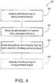
- Fig. 4 includes a flowchart illustrating an example additive manufacturing method 50, as a particular implementation of additive manufacturing method 30, and Fig. 5 includes illustrations corresponding and/or relating to example operations of method 50.
- Fig. 5 illustrates an example of matrix material 20 that includes a non-reactive matrix component 52 and a resin 54 that together comprise matrix material 20.
- non-reactive matrix component 52 includes energy-emissive dopant 22. It will be appreciated, however, that in other examples, energy-emissive dopant 22 may be included in resin 54, in addition or as an alternative to energy-emissive dopant 22 being included in non-reactive matrix component 52.
- Non-reactive matrix component 52 which may include a catalyst in some examples, is a component of matrix material 20 and is generally not reactive to the activating energy 35 or the curing energy 37.
- non-reactive matrix component 52 may carry energy-emissive dopant 22 without reacting to (e.g., solidifying) in response to exposure to the activating energy 35 or the curing energy 37.
- non-reactive matrix component 52 and energy-emissive dopant 22 together may form a larger proportion of matrix material 20 than would energy-emissive dopant 22 alone.
- energy-emissive dopant 22 included with non-reactive matrix component 52 may facilitate and/or increase the accuracy of measuring, mixing, and/or distributing energy-emissive dopant 22 in matrix material 20.
- Method 50 includes applying 56 activating energy to the energy-emissive dopant (e.g., within the non-reactive matrix component 52) to activate the energy-emissive dopant to emit the curing energy.
- activating energy 57 may be applied by an activating energy source 58 and, as indicated in an illustration enlargement, may activate energy-emissive dopant 22 to emit curing energy 59 to provide dopant-activated non-reactive matrix component 60.
- Method 50 includes mixing 62 the dopant-activated non-reactive matrix component 60 and the resin 54 to form matrix material 20.
- Method 50 includes dispensing 64 an additive manufacturing fiber tow, a matrix material, and an energy-emissive dopant, which together may form a solidifiable elongate additive manufacturing fiber composite 65.
- Dispensing 64 an additive manufacturing fiber tow, a matrix material, and an energy-emissive dopant may include dispensing additive manufacturing fiber tow 12 and matrix material 20 (with the dopant-activated non-reactive matrix component 60) concurrently or successively.
- Method 50 may optionally include applying 66 activating energy to the energy-emissive dopant, included with manufacturing fiber tow 12 and matrix material 20, further to activate the energy-emissive dopant to emit the curing energy. As illustrated in Fig.
- activating energy 67 may be applied by an activating energy source 68 and, as indicated in an illustration enlargement, may activate energy-emissive dopant 22 to emit curing energy 69 to provide dopant-activated non-reactive matrix component 60.
- activating energy sources 58 and 68 may be the same energy source, and in other examples activating energy sources 58 and 68 may be separate energy sources and may have different intensities, wavelengths/energies, or other characteristics.
- applying 56 activating energy 57 to the energy-emissive dopant 22 and applying 66 activating energy 67 to the energy-emissive dopant may correspond to first and second applications of activating energy.
- the energy-emissive dopant 22 may emit the curing energy 59, 69 while receiving the activating energy 57, 67 and in other examples the energy-emissive dopant 22 may also continue to emit the curing energy 59, 69 subsequent to application of the activating energy 57, 67.
- Energy-emissive dopant 22 that emits the curing energy 59, 69 while receiving the activating energy 57, 67, and in some examples only while receiving the activating energy 57, 67, may be referred to as fluorescent.
- Energy-emissive dopant 22 that continues to emit the curing energy 59, 69 subsequent to receiving the activating energy 57, 67 may be referred to as phosphorescent.
- energy-emissive dopant 22 that continues to emit the curing energy 59, 69 subsequent to receiving the activating energy 57, 67 may emit or release the curing energy 59, 69 over time and may provide a timed delay to curing of the matrix material 20.
- Table 1 lists as example phosphorescent materials SrHfO3:Ce, YTaO4:Nb, CaWO4, and LaOBr:Tb, which may continue to emit curing energies over persistence times ranging from about 40 ns to several hours.
- Figs. 6-9 illustrate cross-sectional views of respective examples of elongate additive manufacturing fiber composite 10, each of which includes additive manufacturing fiber tow 12 of multiple elongate fibers 14, matrix material 20, and energy-emissive dopant 22.
- Fig. 6 illustrates example 70 of elongate additive manufacturing fiber composite 10, in which energy-emissive dopant 22 is in a distribution 80 that is positioned and/or distributed centrally, or at about a center region of elongate additive manufacturing fiber composite 10.
- Distribution 80 of energy-emissive dopant 22 may be employed, for example, to overcome or address shadowing that may arise in a central and/or center region of elongate additive manufacturing fiber composite 10 from multiple elongate fibers 14 of additive manufacturing fiber tow 12.
- Fig. 7 illustrates example 72 of elongate additive manufacturing fiber composite 10, in which energy-emissive dopant 22 is in a distribution 82 that is positioned and/or distributed in one or more (e.g., two) concentric arrangements within elongate additive manufacturing fiber composite 10.
- Distribution 82 of energy-emissive dopant 22 may employ, for example, different dopants and/or different concentrations of dopant in the concentric arrangements to promote curing and/or stiffness of the elongate additive manufacturing fiber composite 10 after curing.
- Fig. 8 illustrates example 74 of elongate additive manufacturing fiber composite 10, in which energy-emissive dopant 22 is in a distribution 84 that is positioned and/or distributed in multiple radial arrangements within elongate additive manufacturing fiber composite 10, and optionally also with includes energy-emissive dopant 22 positioned and/or distributed centrally, or at about a center region.
- Distribution 84 of energy-emissive dopant 22 may promote curing of and/or adhesion between successive or adjacent layers and/or courses of elongate additive manufacturing fiber composite 10, which may promote intermingling between layers and/or courses of the elongate additive manufacturing fiber composite 10.
- Fig. 9 illustrates example 76 of elongate additive manufacturing fiber composite 10, with a generally flat configuration, in which energy-emissive dopant 22 is in a distribution 86 that is positioned and/or distributed along a central plane or planar region of elongate additive manufacturing fiber composite 10.
- Distribution 86 of energy-emissive dopant 22 may be employed, for example, to overcome or address shadowing that may arise in a central and/or center region of a generally flat elongate additive manufacturing fiber composite 10 from the multiple elongate fibers 14 of additive manufacturing fiber tow 12.
- distributions 80, 82, 84, and 86 of respective examples 70, 72, 74, and 76 are illustrative and that energy-emissive dopant 22 may be positioned and/or distributed in many other arrangements, including a uniform distribution throughout matrix material 20, in accordance with the scope of this disclosure.
- Fig. 10 illustrates example 90 of multiple courses or layers 92 (e.g., two) of elongate additive manufacturing fiber composite 10, with a generally flat configuration, which each include additive manufacturing fiber tow 12 of multiple elongate fibers 14, matrix material 20, and distributions 94 and 96 of respective energy-emissive dopants 98 and 99, that together may be referred to as an energy-emissive dopant 22.
- Energy-emissive dopants 98 and 99 may extend through generally planar regions of example 90 of elongate additive manufacturing fiber composite 10, with energy-emissive dopant 98 extending through a generally central planar region and energy-emissive dopant 99 extending through opposed outer or facial planar regions example 90 of elongate additive manufacturing fiber composite 10.
- Energy-emissive dopants 98 and 99 may be generally analogous, in emitting curing energy in response to receiving activating energy, but may emit energy in different manners, such as at different rates and/or at different energies.
- energy-emissive dopant 98 extending through the generally central planar region may emit curing energy at a higher rate than that of energy-emissive dopant 98, to provide improved inter-laminar bonding.
- two or more energy-emissive dopants that provide different curing rates may facilitate or improve inter-laminar bonding if a first layer cures at a lower rate while a second layer is being applied, thereby allowing the second layer to be applied before the first layer is cured.
- a first dopant may emit an energy, in response to an external activating energy, that may function as an internal activating energy to activate a second dopant to emit a curing energy. It will be appreciated that many combinations of two or more dopants that emit energy in two or more manners may be used together. Moreover, it will be appreciated that arbitrary numbers of courses or layers of elongate additive manufacturing fiber composite 10 may be used in any configuration and that such elongate additive manufacturing fiber composite 10 may be of any cross-sectional shape or configuration.
- Example 90 of Fig. 10 illustrates courses or layers 92 with respective elongate fibers 14 that may be generally parallel to each other. It will be appreciated, however, that other examples may include more than two courses or layers 92, and the elongate fibers 14 of respective courses or layers 92 may be aligned in different directions. For example, successive courses or layers 92, or successive groups of courses or layers 92, may have respective elongate fibers 14 that are transverse (e.g., perpendicular) to each other. In other examples, different courses or layers 92, or different groups of courses or layers 92, may have any orientation, according to design or performance considerations.
- Fig. 11 is a block diagram of a system 100 for additively manufacturing an article.
- System 100 includes a supply 102 of the additive manufacturing fiber tow 12, and a supply 104 of matrix material 20 with energy-emissive dopant 22.
- a delivery guide 106 is positioned to receive the additive manufacturing fiber tow from the supply 102 and the matrix material 20 with energy-emissive dopant 22 from the supply 104 and is configured to dispense them as a solidifiable elongate additive manufacturing fiber composite, such as solidifiable elongate additive manufacturing fiber composite 33 ( Fig. 3 ) or 65 ( Fig. 5 ), for example.
- a drive assembly 108 is operatively coupled to the delivery guide 106 and configured to selectively move the delivery guide 106 in two- or three-dimensions to additively form the solidifiable elongate additive manufacturing fiber composite in an article configuration.
- Delivery guide 106 and/or drive assembly 108 may be referred to as a composite dispenser.
- the solidifiable elongate additive manufacturing fiber composite in the article configuration may refer to the solidifiable elongate additive manufacturing fiber composite at any time after being dispensed, including immediately after any portion of the solidifiable elongate additive manufacturing fiber composite is dispensed in the article configuration, or after the article is completely formed by the solidifiable elongate additive manufacturing fiber composite, or any time therebetween.
- System 100 further includes an activating energy source 110 that applies activating energy to the energy-emissive dopant to activate the energy-emissive dopant to emit the curing energy to effect curing of the matrix material to manufacture the article.
- activating energy source 110 may correspond or be analogous to activating energy source 36 ( Fig. 3 ) and/or activating energy sources 58 and/or 68 ( Fig. 5 ) and may provide at least any of the activating or excitation energies listed in Table 1.
- the activating energy may be or include a penetrating and/or an ionizing activating energy, such as x-rays or gamma rays.
- Activating energy source 110 of system 100 may provide such activating energies, which may be referred to as high-energy activating energies.
- Figs. 12 and 13 illustrate schematic cross-sectional views of example high-energy activating systems 120 and 130 that may be employed with and/or incorporated into system 100.
- Activating systems 120 and 130 include high-energy activating energy sources 122 and 132 (e.g., gamma radiation sources), as examples of activating energy source 110, to activate energy-emissive dopants 124 and 134, respectively.
- energy-emissive dopant 124 may be included with a non-reactive matrix component 126, in a manner similar to that described with reference to Fig. 5 .
- energy-emissive dopant 134 may be included with a matrix material 136 and a fiber tow 137, in a manner similar to that described with reference to Fig. 3 .
- High-energy activating energy sources 122 and 132, emitting gamma radiation may be considered to be emitting ionizing and or penetrating energy.
- High-energy activating systems 120 and 130 include radiation shielding 128 and 138 to minimize extraneous transmission of ionizing and or penetrating energy for safety purposes.
- systems 120 and 130 may include meander pathways 129 and 139 further to minimize extraneous transmission of ionizing and or penetrating energy.
- energy-emissive dopant 124 and non-reactive matrix component 126 may be carried along meander pathway 129 past high-energy activating energy sources 122
- energy-emissive dopant 134 with matrix material 136 and a fiber tow 137 may be carried along meander pathway 139 past high-energy activating energy sources 132.
- high-energy activating energy sources 122 and 132 may generate other high-energy activating energies, such as x-ray radiation.
- the terms “adapted” and “configured” mean that the element, component, or other subject matter is designed and/or intended to perform a given function. Thus, the use of the terms “adapted” and “configured” should not be construed to mean that a given element, component, or other subject matter is simply “capable of” performing a given function but that the element, component, and/or other subject matter is specifically selected, created, implemented, utilized, programmed, and/or designed for the purpose of performing the function. It is also within the scope of the present disclosure that elements, components, and/or other recited subject matter that is recited as being adapted to perform a particular function may additionally or alternatively be described as being configured to perform that function, and vice versa. Similarly, subject matter that is recited as being configured to perform a particular function may additionally or alternatively be described as being operative to perform that function.
- the term "and/or" placed between a first entity and a second entity means one of (1) the first entity, (2) the second entity, and (3) the first entity and the second entity.
- Multiple entries listed with “and/or” should be construed in the same manner, i.e., "one or more" of the entities so conjoined.
- Other entities optionally may be present other than the entities specifically identified by the "and/or” clause, whether related or unrelated to those entities specifically identified.
- a reference to "A and/or B,” when used in conjunction with open-ended language such as “comprising,” may refer, in one example, to A only (optionally including entities other than B); in another example, to B only (optionally including entities other than A); in yet another example, to both A and B (optionally including other entities).
- These entities may refer to elements, actions, structures, steps, operations, values, and the like.
Abstract
Description
- The present disclosure relates to fiber composites for additive manufacturing, and related methods and systems.
- A printing process may use a feedstock material, dispensed from a print head, to additively manufacture an article with successive layers or courses of the feedstock material. The feedstock material may comprise a polymer and reinforcing fibers, such as carbon fibers, that are opaque to visible and ultra-violet light. When the polymer in the feedstock material is a photopolymer, a source of curing energy may be directed at the feedstock material, dispensed by the print head, to solidify the feedstock material. However, when the reinforcing fibers are opaque to the curing energy, they cast shadows and prevent the curing energy, originating directly from the source of curing energy, from irradiating and curing the photopolymer in the shadows.
- Additive manufacturing fiber composites and related systems and methods are disclosed.
- Additive manufacturing fiber composites comprise a bundle of elongate fibers and a matrix material, with an energy-emissive dopant. The matrix material holds or encompasses the elongate fibers of the additive manufacturing fiber tow. The energy-emissive dopant emits a curing energy in response to receiving an activating energy, and the curing energy effects curing of the solidifiable matrix material so that it solidifies to a rigid or semi-rigid matrix material. The activating energy may penetrate or pass-through the elongate fibers to activate the energy-emissive dopant to provide curing of the matrix material throughout the additive manufacturing fiber composite.
- Methods of additively manufacturing an article include dispensing an additive manufacturing fiber tow, a solidifiable matrix material, and an energy-emissive dopant. The method includes applying the activating energy to the energy-emissive dopant to activate the energy-emissive dopant to emit the curing energy.
- Systems to additively manufacture an article include a supply of additive manufacturing fiber tow, a supply of matrix material with energy-emissive dopant, a composite dispenser to dispense the additive manufacturing fiber tow with the solidifiable matrix material, and an activating energy source that applies activating energy to the energy-emissive dopant to activate the energy-emissive dopant to emit the curing energy to effect curing of the matrix material.
-
-
Fig. 1 is a schematic view of an elongate additive manufacturing fiber composite. -
Fig. 2 includes a flowchart illustrating an example additive manufacturing method. -
Fig. 3 includes illustrations corresponding to example operations of the method ofFig. 2 . -
Fig. 4 includes a flowchart illustrating another example additive manufacturing method. -
Fig. 5 includes illustrations corresponding and/or relating to example operations of the method ofFig. 4 . -
Fig. 6 illustrates a cross-sectional view of a first distribution of energy-emissive dopant in a first example elongate additive manufacturing fiber composite. -
Fig. 7 illustrates a cross-sectional view of a second distribution of energy-emissive dopant in a second example elongate additive manufacturing fiber composite. -
Fig. 8 illustrates a cross-sectional view of a third distribution of energy-emissive dopant in a third example elongate additive manufacturing fiber composite. -
Fig. 9 illustrates a cross-sectional view of a fourth distribution of energy-emissive dopant in a fourth example elongate additive manufacturing fiber composite. -
Fig. 10 illustrates an example of multiple courses or layers of elongate additive manufacturing fiber composite. -
Fig. 11 is a schematic illustration representing a system for additive manufacturing that utilize multi-part filaments. -
Fig. 12 illustrates a schematic cross-sectional view of a first system with a high-energy activating energy source to activate an energy-emissive dopant. -
Fig. 13 illustrates a schematic cross-sectional view of a second system with a high-energy activating energy source to activate an energy-emissive dopant. - Additive manufacturing fiber composites and related systems and methods are disclosed herein. Generally, in the figures, elements that are likely to be included in a given example are illustrated in solid lines, while elements that are optional to a given example are illustrated in broken lines. However, elements that are illustrated in solid lines are not essential to all examples of the present disclosure, and an element shown in solid lines may be omitted from a particular example without departing from the scope of the present disclosure.
- As schematically illustrated in
Fig. 1 , an elongate additivemanufacturing fiber composite 10 is shown. Elongate additivemanufacturing fiber composite 10 includes an additivemanufacturing fiber tow 12 of multipleelongate fibers 14. Elongate additivemanufacturing fiber composite 10 further includes amatrix material 20, with an energy-emissive dopant 22.Matrix material 20 holds or encompasseselongate fibers 14 of additivemanufacturing fiber tow 12. - The
elongate fibers 14 of additivemanufacturing fiber tow 12 typically, or at least in their initially manufactured form, havelengths 15 that are significantly greater than theirdiameters 16. (Diameter 16 herein refers to a sectional, lateral dimension through a center of a body and does not imply or require that the body have a circular cross section. Elongatefibers 14 have cross sections that may be circular or non-circular.) As illustrative, non-exclusive examples, theelongate fibers 14 each may have lengths that are at least 10, at least 100, at least 1,000, at least 10,000, at least 100,000, or at least 1,000,000 times greater thandiameter 16. In accordance with these examples, theelongate fibers 14 may be referred to as being continuous or chopped. Elongate additivemanufacturing fiber composite 10 is configured for use as a feedstock, or at least as a component of a feedstock, for an additive manufacturing system, such as may be referred to as a 3-D printer or a fused filament fabrication (FFF) system, for example.Elongate fibers 14 may include, comprise, or be formed of one or more of carbon fibers, glass fibers, aramid fibers, boron fibers, silicon-carbide fibers, ceramic fibers, optical fibers, fiber bundles, fiber weaves, fiber braids, wires, metal wires, conductive wire, and wire bundles. -
Matrix material 20 may take the form of or include one or more of a polymer, a resin, a thermoset, and/or a photopolymer. As used herein, a photopolymer is a polymer that is configured to be cured in the presence of light, such as one or more of ultraviolet light, visible-light, or infrared-light, for example.Matrix material 20 may initially have a solidifiable state and may subsequently have a solidified state. In its solidifiable state,matrix material 20 is in a liquid phase or in a similar flowable state (e.g., not in a rigidly solid form) that may be intermixed with and/or applied to encompasselongate fibers 14 to create the elongate additivemanufacturing fiber composite 10. The elongate additivemanufacturing fiber composite 10 may include thematrix material 20 in the solidifiable state as a pre-impregnated, or prepreg, composite stock. In its solidified state,matrix material 20 is in a rigidly, or semi-rigidly, non-flowable state. - In some examples,
matrix material 20 may be curable so as to transition from the solidifiable state to the solidified state as a result of cross-linking of polymer chains, such as responsive to an application of a curing energy. Energy-emissive dopant 22 may include or be configured as a liquid, a gas, and/or a solid that is withinmatrix material 20 and that emits a curing energy in response to receiving an activating energy, which may be different from the curing energy. The curing energy emitted by energy-emissive dopant 22 effects curing ofmatrix material 20 to transition from the solidifable state to the solidified state, as described below in greater detail. As a solid, energy-emissive dopant 22 may be and/or include one or more of particles (e.g., nanoparticles), elongates, threads, and/or fibers. In some examples in whichelongate fibers 14 include carbon fibers, energy-emissive dopant 22 may be and/or include particles (e.g., nanoparticles). - Generally,
matrix material 20 may transition from the solidifiable state to the solidified state by applying a curing energy that may comprise one or more of heat, ultraviolet light, visible light, or infrared light, for example. The curing energy may be applied by a curing energy source (e.g., light or heat source), and/or may be applied by energy-emissive dopant 22 emitting the curing energy in response to receiving the activating energy. In some examples,elongate fibers 14 of additivemanufacturing fiber tow 12 may block or shadow illuminating curing energy from a curing energy source and prevent the curing energy from reaching at least some of thematrix material 20. - In examples, therefore,
matrix material 20 may be transitioned from the solidifiable state to the solidified state by applying an activating energy that activates energy-emissive dopant 22 throughoutmatrix material 20 so that energy-emissive dopant 22 emits the curing energy and effects curing ofmatrix material 20. In some examples, the activating energy may be a penetrating and/or an ionizing activating energy (e.g., x-rays, gamma rays, electron-beams, sub-atomic particles, etc.) or may be a non-ionizing activating energy (e.g., ultraviolet (UV), visible, infrared (IR), radio frequency (RF), microwaves, magnetic or electric fields, etc.). In some examples, a penetrating and/or an ionizing activating energy may penetrate or pass throughelongate fibers 14 to reachmatrix material 20 that could otherwise be obscured by theelongate fibers 14. In addition to reachingmatrix material 20 that could otherwise be obscured or shadowed by theelongate fibers 14, such activating energy activates energy-emissive dopant 22 throughoutmatrix material 20 so that energy-emissive dopant 22 emits the curing energy and effects curing ofmatrix material 20 throughout elongate additivemanufacturing fiber composite 10. In examples, the activating energy may also effect curing ofmatrix material 20 directly upon illuminating or impinging upon thematrix material 20. - Table 1 lists example materials that may be employed as and/or included in energy-
emissive dopant 22, together with corresponding activating energies (as wavelengths in nanometers (nm) or energy type), curing energies that are emitted (as wavelengths in nm, or energy type), and persistence times (nanoseconds (nS)) for materials that may continue to emit curing energy subsequent to activation energy being applied, as described below in greater detail. One or more of the dopants of Table 1 may include and/or be configured as nanoparticles, which may be generally of a size of 1 nm to 100 nm.Table 1 Energy-Emissive Dopant Excitation or Activating Energy Emission Persistence Time Au 260 nm 3500 nm NaYF4(Er/Tm,Yb)/NaYF4 (core-shell configuration) 980 nm 365 nm Iron Oxide Nanoparticles Alternating Current Magnetic Field Thermal Aluminum Nanorods (e.g., plasmonic nanostructures or nanoantennas) Electron-Beam 260 nm -600 nm Au NP (nanoparticles) Radio Frequency Thermal BaF2 X-Ray 180-220 nm YAlO3:Ce X-Ray 360 nm LuAlO3:Ce X-Ray 365 nm ZnO:Ga X-ray 390 nm SrHfO3:Ce X-Ray 390 nm 40 ns Lu2SiO5:Ce X-Ray 390 nm YTaO4:Nb X-Ray 410 nm 2,000 ns PbWO4 X-Ray 410 nm CaWO4 X-Ray 420 nm 6,000 ns K2Lal5:Ce X-Ray 420 nm LaOBr:Tb X-Ray 425 nm 1,000,000 ns Li2MgGeO4:Mn2+ 254 nm 532 nm >1.8x10¹³ ns (> 5 hours) emissive dopant 22, and may or may not include persistence times within the range of 40 ns - 5 hours. Moreover, wavelengths generally in the range of 10 nm to about 450 nm may be considered ultraviolet (UV) light, which may correspond to a curing energy in some examples. -
Fig. 2 includes a flowchart illustrating an exampleadditive manufacturing method 30, andFig. 3 includes an illustration corresponding and/or relating to example operations ofmethod 30. -
Method 30 includes dispensing 32 an additive manufacturing fiber tow, a matrix material, and an energy-emissive dopant. As illustrated inFig. 3 , for example, the additive manufacturing fiber tow may include additivemanufacturing fiber tow 12, and the matrix material and energy-emissive dopant may includematrix material 20 with energy-emissive dopant 22, which together may form a solidifiable elongate additivemanufacturing fiber composite 33. For example, solidifiable elongate additivemanufacturing fiber composite 33 may correspond to elongate additivemanufacturing fiber composite 10 withmatrix material 20 in a solidifiable state.Method 30 includes applying 34 activating energy to the energy-emissive dopant to activate the energy-emissive dopant to emit the curing energy. Applying 34 activating energy to the energy-emissive dopant may include applying a penetrating and/or an ionizing activating energy (e.g., x-rays, gamma rays, etc.). As illustrated inFig. 3 , for example, activatingenergy 35 may be applied by an activatingenergy source 36 and, as indicated in an illustration enlargement, may activate energy-emissive dopant 22 to emit curingenergy 37 to provide solidified elongate additivemanufacturing fiber composite 38. For example, solidified elongate additivemanufacturing fiber composite 38 may correspond to elongate additivemanufacturing fiber composite 10 withmatrix material 20 in a solidified state. - Dispensing 32 an additive manufacturing fiber tow, a matrix material, and an energy-emissive dopant may include dispensing additive manufacturing fiber tow, matrix material, and energy-emissive dopant separately, concurrently, and/or in any combination, sub-combination, or sequence. In
Fig. 3 , for example,matrix material 20 is illustrated as including energy-emissive dopant 22 when dispensed with additivemanufacturing fiber tow 12. In other examples,matrix material 20 and energy-emissive dopant 22 may be dispensed separately. Also, applying 34 activatingenergy 35 to the energy-emissive dopant 22 to activate the energy-emissive dopant 22 to emit the curingenergy 37 may occur at any time (e.g., before, during, and/or after) with regard to dispensing 32 of an additive manufacturing fiber tow, a matrix material, and an energy-emissive dopant. -
Fig. 4 includes a flowchart illustrating an exampleadditive manufacturing method 50, as a particular implementation ofadditive manufacturing method 30, andFig. 5 includes illustrations corresponding and/or relating to example operations ofmethod 50.Fig. 5 illustrates an example ofmatrix material 20 that includes anon-reactive matrix component 52 and aresin 54 that together comprisematrix material 20. In the example ofFigs. 4 and5 ,non-reactive matrix component 52 includes energy-emissive dopant 22. It will be appreciated, however, that in other examples, energy-emissive dopant 22 may be included inresin 54, in addition or as an alternative to energy-emissive dopant 22 being included innon-reactive matrix component 52. -
Non-reactive matrix component 52, which may include a catalyst in some examples, is a component ofmatrix material 20 and is generally not reactive to the activatingenergy 35 or the curingenergy 37. As a result,non-reactive matrix component 52 may carry energy-emissive dopant 22 without reacting to (e.g., solidifying) in response to exposure to the activatingenergy 35 or the curingenergy 37. Moreover,non-reactive matrix component 52 and energy-emissive dopant 22 together may form a larger proportion ofmatrix material 20 than would energy-emissive dopant 22 alone. As a result, energy-emissive dopant 22 included withnon-reactive matrix component 52 may facilitate and/or increase the accuracy of measuring, mixing, and/or distributing energy-emissive dopant 22 inmatrix material 20. -
Method 50 includes applying 56 activating energy to the energy-emissive dopant (e.g., within the non-reactive matrix component 52) to activate the energy-emissive dopant to emit the curing energy. As illustrated inFig. 5 , for example, activatingenergy 57 may be applied by an activatingenergy source 58 and, as indicated in an illustration enlargement, may activate energy-emissive dopant 22 to emit curingenergy 59 to provide dopant-activatednon-reactive matrix component 60.Method 50 includes mixing 62 the dopant-activatednon-reactive matrix component 60 and theresin 54 to formmatrix material 20.Method 50 includes dispensing 64 an additive manufacturing fiber tow, a matrix material, and an energy-emissive dopant, which together may form a solidifiable elongate additivemanufacturing fiber composite 65. Dispensing 64 an additive manufacturing fiber tow, a matrix material, and an energy-emissive dopant may include dispensing additivemanufacturing fiber tow 12 and matrix material 20 (with the dopant-activated non-reactive matrix component 60) concurrently or successively.Method 50 may optionally include applying 66 activating energy to the energy-emissive dopant, included withmanufacturing fiber tow 12 andmatrix material 20, further to activate the energy-emissive dopant to emit the curing energy. As illustrated inFig. 5 , for example, activatingenergy 67 may be applied by an activatingenergy source 68 and, as indicated in an illustration enlargement, may activate energy-emissive dopant 22 to emit curingenergy 69 to provide dopant-activatednon-reactive matrix component 60. In some examples, activatingenergy sources energy sources - In examples, applying 56 activating
energy 57 to the energy-emissive dopant 22 and applying 66 activatingenergy 67 to the energy-emissive dopant may correspond to first and second applications of activating energy. In some examples, the energy-emissive dopant 22 may emit the curingenergy energy emissive dopant 22 may also continue to emit the curingenergy energy emissive dopant 22 that emits the curingenergy energy energy emissive dopant 22 that continues to emit the curingenergy energy emissive dopant 22 that continues to emit the curingenergy energy energy matrix material 20. As examples, Table 1 lists as example phosphorescent materials SrHfO3:Ce, YTaO4:Nb, CaWO4, and LaOBr:Tb, which may continue to emit curing energies over persistence times ranging from about 40 ns to several hours. -
Figs. 6-9 illustrate cross-sectional views of respective examples of elongate additivemanufacturing fiber composite 10, each of which includes additivemanufacturing fiber tow 12 of multipleelongate fibers 14,matrix material 20, and energy-emissive dopant 22.Fig. 6 illustrates example 70 of elongate additivemanufacturing fiber composite 10, in which energy-emissive dopant 22 is in adistribution 80 that is positioned and/or distributed centrally, or at about a center region of elongate additivemanufacturing fiber composite 10.Distribution 80 of energy-emissive dopant 22 may be employed, for example, to overcome or address shadowing that may arise in a central and/or center region of elongate additivemanufacturing fiber composite 10 from multipleelongate fibers 14 of additivemanufacturing fiber tow 12. -
Fig. 7 illustrates example 72 of elongate additivemanufacturing fiber composite 10, in which energy-emissive dopant 22 is in adistribution 82 that is positioned and/or distributed in one or more (e.g., two) concentric arrangements within elongate additivemanufacturing fiber composite 10.Distribution 82 of energy-emissive dopant 22 may employ, for example, different dopants and/or different concentrations of dopant in the concentric arrangements to promote curing and/or stiffness of the elongate additivemanufacturing fiber composite 10 after curing. -
Fig. 8 illustrates example 74 of elongate additivemanufacturing fiber composite 10, in which energy-emissive dopant 22 is in adistribution 84 that is positioned and/or distributed in multiple radial arrangements within elongate additivemanufacturing fiber composite 10, and optionally also with includes energy-emissive dopant 22 positioned and/or distributed centrally, or at about a center region.Distribution 84 of energy-emissive dopant 22 may promote curing of and/or adhesion between successive or adjacent layers and/or courses of elongate additivemanufacturing fiber composite 10, which may promote intermingling between layers and/or courses of the elongate additivemanufacturing fiber composite 10. -
Fig. 9 illustrates example 76 of elongate additivemanufacturing fiber composite 10, with a generally flat configuration, in which energy-emissive dopant 22 is in adistribution 86 that is positioned and/or distributed along a central plane or planar region of elongate additivemanufacturing fiber composite 10.Distribution 86 of energy-emissive dopant 22 may be employed, for example, to overcome or address shadowing that may arise in a central and/or center region of a generally flat elongate additivemanufacturing fiber composite 10 from the multipleelongate fibers 14 of additivemanufacturing fiber tow 12. It will be appreciated thatdistributions emissive dopant 22 may be positioned and/or distributed in many other arrangements, including a uniform distribution throughoutmatrix material 20, in accordance with the scope of this disclosure. -
Fig. 10 illustrates example 90 of multiple courses or layers 92 (e.g., two) of elongate additivemanufacturing fiber composite 10, with a generally flat configuration, which each include additivemanufacturing fiber tow 12 of multipleelongate fibers 14,matrix material 20, anddistributions emissive dopants emissive dopant 22. Energy-emissive dopants manufacturing fiber composite 10, with energy-emissive dopant 98 extending through a generally central planar region and energy-emissive dopant 99 extending through opposed outer or facial planar regions example 90 of elongate additivemanufacturing fiber composite 10. Energy-emissive dopants emissive dopant 98 extending through the generally central planar region may emit curing energy at a higher rate than that of energy-emissive dopant 98, to provide improved inter-laminar bonding. For example, two or more energy-emissive dopants that provide different curing rates may facilitate or improve inter-laminar bonding if a first layer cures at a lower rate while a second layer is being applied, thereby allowing the second layer to be applied before the first layer is cured. Timing issues with inter-laminar bonding can be significant in forming large-scale composites. In other examples, a first dopant may emit an energy, in response to an external activating energy, that may function as an internal activating energy to activate a second dopant to emit a curing energy. It will be appreciated that many combinations of two or more dopants that emit energy in two or more manners may be used together. Moreover, it will be appreciated that arbitrary numbers of courses or layers of elongate additivemanufacturing fiber composite 10 may be used in any configuration and that such elongate additivemanufacturing fiber composite 10 may be of any cross-sectional shape or configuration. - Example 90 of
Fig. 10 illustrates courses orlayers 92 with respectiveelongate fibers 14 that may be generally parallel to each other. It will be appreciated, however, that other examples may include more than two courses or layers 92, and theelongate fibers 14 of respective courses or layers 92 may be aligned in different directions. For example, successive courses or layers 92, or successive groups of courses or layers 92, may have respectiveelongate fibers 14 that are transverse (e.g., perpendicular) to each other. In other examples, different courses or layers 92, or different groups of courses or layers 92, may have any orientation, according to design or performance considerations. -
Fig. 11 is a block diagram of asystem 100 for additively manufacturing an article.System 100 includes asupply 102 of the additivemanufacturing fiber tow 12, and asupply 104 ofmatrix material 20 with energy-emissive dopant 22. Adelivery guide 106 is positioned to receive the additive manufacturing fiber tow from thesupply 102 and thematrix material 20 with energy-emissive dopant 22 from thesupply 104 and is configured to dispense them as a solidifiable elongate additive manufacturing fiber composite, such as solidifiable elongate additive manufacturing fiber composite 33 (Fig. 3 ) or 65 (Fig. 5 ), for example. Adrive assembly 108 is operatively coupled to thedelivery guide 106 and configured to selectively move thedelivery guide 106 in two- or three-dimensions to additively form the solidifiable elongate additive manufacturing fiber composite in an article configuration.Delivery guide 106 and/or drive assembly 108 may be referred to as a composite dispenser. The solidifiable elongate additive manufacturing fiber composite in the article configuration may refer to the solidifiable elongate additive manufacturing fiber composite at any time after being dispensed, including immediately after any portion of the solidifiable elongate additive manufacturing fiber composite is dispensed in the article configuration, or after the article is completely formed by the solidifiable elongate additive manufacturing fiber composite, or any time therebetween. -
System 100 further includes an activatingenergy source 110 that applies activating energy to the energy-emissive dopant to activate the energy-emissive dopant to emit the curing energy to effect curing of the matrix material to manufacture the article. As examples, activatingenergy source 110 may correspond or be analogous to activating energy source 36 (Fig. 3 ) and/or activatingenergy sources 58 and/or 68 (Fig. 5 ) and may provide at least any of the activating or excitation energies listed in Table 1. - As described above, some examples of the activating energy may be or include a penetrating and/or an ionizing activating energy, such as x-rays or gamma rays. Activating
energy source 110 of system 100 (Fig. 11 ) may provide such activating energies, which may be referred to as high-energy activating energies. In connection with applying such high-energy activating energies,Figs. 12 and 13 illustrate schematic cross-sectional views of example high-energy activating systems system 100. Activatingsystems energy sources 122 and 132 (e.g., gamma radiation sources), as examples of activatingenergy source 110, to activate energy-emissive dopants - In high-
energy activating system 120, energy-emissive dopant 124 may be included with anon-reactive matrix component 126, in a manner similar to that described with reference toFig. 5 . In high-energy activating system 130, energy-emissive dopant 134 may be included with amatrix material 136 and afiber tow 137, in a manner similar to that described with reference toFig. 3 . High-energy activatingenergy sources energy activating systems radiation shielding systems meander pathways emissive dopant 124 andnon-reactive matrix component 126 may be carried alongmeander pathway 129 past high-energy activatingenergy sources 122, and energy-emissive dopant 134 withmatrix material 136 and afiber tow 137 may be carried alongmeander pathway 139 past high-energy activatingenergy sources 132. It will be appreciated that in other examples high-energy activatingenergy sources - Illustrative, non-exclusive examples of inventive subject matter according to the present disclosure are described in the following enumerated paragraphs:
- A. A method of additively manufacturing an article, comprising:
- dispensing an additive manufacturing fiber tow, a solidifiable matrix material, and an energy-emissive dopant, wherein the energy-emissive dopant emits a curing energy in response to receiving an activating energy, and the curing energy effects curing of the solidifiable matrix material; and
- applying activating energy to the energy-emissive dopant to activate the energy-emissive dopant to emit the curing energy.
- A1. The method of paragraph A, wherein dispensing the additive manufacturing fiber tow, the solidifiable matrix material, and the energy-emissive dopant includes arranging the additive manufacturing fiber tow in an article configuration with the solidifiable matrix material and the energy-emissive dopant.
- A2. The method of paragraph A1, wherein applying the activating energy to the energy-emissive dopant includes applying the activating energy to the energy-emissive dopant with the additive manufacturing fiber tow and the solidifiable matrix material in the article configuration.
- A3. The method of any of paragraphs A-A2, wherein applying the activating energy to the energy-emissive dopant includes applying the activating energy to the energy-emissive dopant without the additive manufacturing fiber tow.
- A4. The method of any of paragraphs A-A3, wherein the energy-emissive dopant emits the curing energy while receiving the activating energy.
- A5. The method of any paragraphs A-A3, wherein the energy-emissive dopant continues to emit the curing energy subsequent to application of the activating energy.
- A6. The method of any of paragraphs A-A5, wherein the solidifiable matrix material includes a non-reactive matrix component and a resin and the energy-emissive dopant is included in the non-reactive matrix component, wherein the method further comprises mixing the resin with the non-reactive matrix component and the energy-emissive dopant, and wherein dispensing the additive manufacturing fiber tow, the solidifiable matrix material, and the energy-emissive dopant includes applying the solidifiable matrix material and the energy-emissive dopant to the additive manufacturing fiber tow.
- A7. The method of any of paragraphs A-A6, wherein the curing energy and the activating energy are different.
- A8. The method of paragraph A6, wherein the activating energy is of a penetrating energy to penetrate the additive manufacturing fiber tow and the solidifiable matrix material to activate the energy-emissive dopant.
- A9. The method of paragraph A6 or A7, wherein the activating energy includes ionizing radiation to penetrate the additive manufacturing fiber tow and the solidifiable matrix material to activate the energy-emissive dopant.
- A10. The method of paragraph A9, wherein the activating energy includes gamma radiation.
- A11. The method of paragraph A9 or A10, wherein the activating energy includes x-ray radiation.
- A12. The method of any of paragraphs A-A11, wherein the energy-emissive dopant includes nanoparticles.
- A13. The method of any of paragraphs A-A11, wherein the energy-emissive dopant is configured as nanoparticles.
- A14. The method of any of paragraphs A-A13, wherein the additive manufacturing fiber tow with the solidifiable matrix material and the energy-emissive dopant that emits a curing energy correspond to a first additive manufacturing fiber tow with a first solidifiable matrix material and a first energy-emissive dopant that emits a first curing energy, respectively, wherein the first curing energy effects curing of the first solidifiable matrix material at a first cure rate, and wherein the method further comprises dispensing a second additive manufacturing fiber tow on the first additive manufacturing fiber tow with a second solidifiable matrix material and a second energy-emissive dopant, wherein the second energy-emissive dopant emits a second curing energy in response to receiving the activating energy, and the second curing energy effects curing of the second solidifiable matrix material at a second cure rate that is different than the first cure rate.
- A15. An article manufactured according to the method of any of paragraphs A-A14.
- B. An additive manufacturing system, comprising:
- a supply of additive manufacturing fiber tow;
- a fiber tow dispenser to dispense the additive manufacturing fiber tow;
- a supply of solidifiable matrix material with an energy-emissive dopant that emits a curing energy in response to receiving an activating energy, wherein the curing energy effects curing of the solidifiable matrix material;
- a composite dispenser to dispense the additive manufacturing fiber tow with the solidifiable matrix material; and
- an activating energy source to apply activating energy to the energy-emissive dopant to activate the energy-emissive dopant to emit the curing energy.
- B1. The system of paragraph B, wherein the activating energy source includes a first activating energy source configured to apply activating energy to the energy-emissive dopant separate from the additive manufacturing fiber tow and prior to the solidifiable matrix material being dispensed with the additive manufacturing fiber.
- B2. The system of paragraph B or B1, wherein the activating energy source includes a second activating energy source configured to apply activating energy to the energy-emissive dopant after the solidifiable matrix material is dispensed with the additive manufacturing fiber.
- B3. The system of any of paragraphs B-B2, wherein the solidifiable matrix material includes a non-reactive matrix component and a resin and the energy-emissive dopant is included in the non-reactive matrix component, and wherein the system further comprises a mixer to mix the resin with the non-reactive matrix component and the energy-emissive dopant as a mixture and to dispense the mixture with additive manufacturing fiber tow.
- B4. The system of paragraph B1, wherein the solidifiable matrix material includes an non-reactive matrix component and a resin and the energy-emissive dopant is included in the non-reactive matrix component, wherein the system further comprises a mixer to mix the resin with the non-reactive matrix component and the energy-emissive dopant as a mixture and to deliver the mixture to the composite dispenser, and wherein the first activating energy source is configured to apply activating energy to the energy-emissive dopant in the non-reactive matrix component prior to the mixer mixing the resin with the non-reactive matrix component and the energy-emissive dopant.
- B5. The system of any of paragraphs B-B4, wherein the curing energy and the activating energy are different.
- B6. The system of any of paragraphs B-B5, wherein the activating energy source applies activating energy that includes ionizing radiation.
- B7. The system of paragraph B6, wherein the activating energy includes gamma radiation.
- B8. The system of paragraph B6 or B7, wherein the activating energy includes x-ray radiation.
- B9. The system of any of paragraphs B-B8, wherein the energy-emissive dopant includes nanoparticles.
- B10. The system of any of paragraphs B-B8, wherein the energy-emissive dopant is configured as nanoparticles.
- B11. The use of the system of any of paragraphs B-B10 to additively manufacture an article.
- C. An article, comprising:
- one or more courses of additive manufacturing fiber tow; and
- a solidified matrix material with an energy-emissive dopant applied to each course, wherein the energy-emissive dopant emits a curing energy in response to receiving an activating energy to effect curing of the solidified matrix material.
- C1. The article of paragraph C, wherein the activating energy includes ionizing energy.
- C2. The article of paragraph C or C1, wherein the solidified matrix material includes a resin.
- C3. The article of any of paragraphs C-C2, wherein the solidified matrix material includes a non-reactive matrix component.
- C4. The article of any of paragraphs C-C3, wherein the energy-emissive dopant includes nanoparticles.
- C5. The article of any of paragraphs C-C3, wherein the energy-emissive dopant is configured as nanoparticles.
- C6. The article of any of paragraphs C-C5, wherein the energy-emissive dopant includes a first energy-emissive dopant that emits a curing energy in a first manner, and wherein the solidified matrix material of at least one of the one or more courses of additive manufacturing fiber tow further includes a second energy-emissive dopant that emits the curing energy in a second manner that is different from the first manner.
- D. An elongate additive manufacturing fiber composite, comprising:
- multiple elongate fibers; and
- a matrix material that encompasses the elongate fibers, the matrix material including an energy-emissive dopant that emits a curing energy in response to receiving an activating energy to effect curing of the matrix material.
- D1. The elongate additive manufacturing fiber composite of paragraph D, wherein the energy-emissive dopant includes nanoparticles.
- D2. The elongate additive manufacturing fiber composite of paragraph D, wherein the energy-emissive dopant is configured as nanoparticles.
- D3. The elongate additive manufacturing fiber composite of any of paragraphs D-D2, wherein the energy-emissive dopant emits the curing energy while receiving the activating energy.
- D4. The elongate additive manufacturing fiber composite of any of paragraphs D-D2, wherein the energy-emissive dopant continues to emit the curing energy subsequent to application of the activating energy.
- D5. The elongate additive manufacturing fiber composite of any of paragraphs D-D5, wherein the matrix material includes a photopolymer that is configured to be cured in the presence of light of the curing energy.
- D6. The elongate additive manufacturing fiber composite of any of paragraphs D-D5, wherein the energy-emissive dopant includes a first energy-emissive dopant that emits a curing energy in a first manner, and wherein the matrix material further includes a second energy-emissive dopant that emits the curing energy in a second manner than is different from the first manner.
- D7. The elongate additive manufacturing fiber composite of any of paragraphs D-D6, wherein the elongate additive manufacturing fiber composite includes a pre-impregnated composite stock.
- D8. The use of the elongate additive manufacturing fiber composite of any of paragraphs D-D7 to additively manufacture an article.
- As used herein, the terms "adapted" and "configured" mean that the element, component, or other subject matter is designed and/or intended to perform a given function. Thus, the use of the terms "adapted" and "configured" should not be construed to mean that a given element, component, or other subject matter is simply "capable of" performing a given function but that the element, component, and/or other subject matter is specifically selected, created, implemented, utilized, programmed, and/or designed for the purpose of performing the function. It is also within the scope of the present disclosure that elements, components, and/or other recited subject matter that is recited as being adapted to perform a particular function may additionally or alternatively be described as being configured to perform that function, and vice versa. Similarly, subject matter that is recited as being configured to perform a particular function may additionally or alternatively be described as being operative to perform that function.
- As used herein, the term "and/or" placed between a first entity and a second entity means one of (1) the first entity, (2) the second entity, and (3) the first entity and the second entity. Multiple entries listed with "and/or" should be construed in the same manner, i.e., "one or more" of the entities so conjoined. Other entities optionally may be present other than the entities specifically identified by the "and/or" clause, whether related or unrelated to those entities specifically identified. Thus, as a non-limiting example, a reference to "A and/or B," when used in conjunction with open-ended language such as "comprising," may refer, in one example, to A only (optionally including entities other than B); in another example, to B only (optionally including entities other than A); in yet another example, to both A and B (optionally including other entities). These entities may refer to elements, actions, structures, steps, operations, values, and the like.
- The various disclosed elements of apparatuses and systems and steps of methods disclosed herein are not required to all apparatuses, systems, and methods according to the present disclosure, and the present disclosure includes all novel and non-obvious combinations and subcombinations of the various elements and steps disclosed herein. Moreover, one or more of the various elements and steps disclosed herein may define independent inventive subject matter that is separate and apart from the whole of a disclosed apparatus, system, or method. Accordingly, such inventive subject matter is not required to be associated with the specific apparatuses, systems, and methods that are expressly disclosed herein, and such inventive subject matter may find utility in apparatuses, systems, and/or methods that are not expressly disclosed herein.
Claims (15)
- A method of additively manufacturing an article, comprising:dispensing an additive manufacturing fiber tow (12), a solidifiable matrix material (20), and an energy-emissive dopant (22), wherein the energy-emissive dopant (22) emits a curing energy (37, 59, 69) in response to receiving an activating energy (35, 57, 67), and the curing energy (37, 59, 69) effects curing of the solidifiable matrix material (20); andapplying activating energy (35, 57, 67) to the energy-emissive dopant (22) to activate the energy-emissive dopant (22) to emit the curing energy (37, 59, 69).
- The method of claim 1, wherein dispensing the additive manufacturing fiber tow (12), the solidifiable matrix material (20), and the energy-emissive dopant (22) includes arranging the additive manufacturing fiber tow (12) in an article configuration with the solidifiable matrix material (20) and the energy-emissive dopant (22).
- The method of claim 2, wherein applying the activating energy (35, 57, 67) to the energy-emissive dopant (22) includes applying the activating energy (35, 57, 67) to the energy-emissive dopant (22) with the additive manufacturing fiber tow (12) and the solidifiable matrix material (20) in the article configuration.
- The method of one of claims 1 to 3, wherein applying the activating energy (35, 57, 67) to the energy-emissive dopant (22) includes applying the activating energy (35, 57, 67) to the energy-emissive dopant (22) without the additive manufacturing fiber tow (12).
- The method of one of claims 1 to 4, wherein the solidifiable matrix material (20) includes a non-reactive matrix component and a resin and the energy-emissive dopant (22) is included in the non-reactive matrix component, wherein the method further comprises mixing the resin with the non-reactive matrix component and the energy-emissive dopant (22), and wherein dispensing the additive manufacturing fiber tow (12), the solidifiable matrix material (20), and the energy-emissive dopant (22) includes applying the solidifiable matrix material (20) and the energy-emissive dopant (22) to the additive manufacturing fiber tow (12).
- The method of one of claims 1 to 5, wherein the activating energy (35, 57, 67) is of a penetrating energy to penetrate the additive manufacturing fiber tow (12) and the solidifiable matrix material (20) to activate the energy-emissive dopant (22).
- The method of claim 6, wherein the activating energy (35, 57, 67) includes x-ray radiation.
- The method of one of claims 1 to 7, wherein the energy-emissive dopant (22) includes nanoparticles.
- An additive manufacturing system, comprising:a supply of additive manufacturing fiber tow (12);a supply of solidifiable matrix material (20) with an energy-emissive dopant (22) that emits a curing energy (37, 59, 69) in response to receiving an activating energy (35, 57, 67), wherein the curing energy effects curing of the solidifiable matrix material (20);a composite dispenser to dispense the additive manufacturing fiber tow (12) with the solidifiable matrix material (20); andan activating energy source (36, 58, 68) to apply activating energy (35, 57, 67) to the energy-emissive dopant (22) to activate the energy-emissive dopant (22) to emit the curing energy (37, 59, 69).
- The system of claim 9, wherein the activating energy source (36, 58, 68) includes a first activating energy source configured to apply activating energy to the energy-emissive dopant (22) separate from the additive manufacturing fiber tow (12) and prior to the solidifiable matrix material (20) being dispensed with the additive manufacturing fiber tow (12).
- The system of claim 10, wherein the activating energy source (36, 58, 68) includes a second activating energy source configured to apply activating energy to the energy-emissive dopant (22) after the solidifiable matrix material (20) is dispensed with the additive manufacturing fiber tow (12).
- The system of one of claims 9 to 11, wherein the activating energy source (36, 58, 68) is configured to apply activating energy to the energy-emissive dopant (22) after the solidifiable matrix material (20) is dispensed with the additive manufacturing fiber tow (12) in the article configuration.
- The system of one of claims 9 to 12, wherein the solidifiable matrix material (20) includes a non-reactive matrix component and a resin and the energy-emissive dopant (22) is included in the non-reactive matrix component, and wherein the system further comprises a mixer to mix the resin with the non-reactive matrix component and the energy-emissive dopant (22) as a mixture and to dispense the mixture with the additive manufacturing fiber tow (12).
- The system of claim 13, wherein the activating energy is applied to the energy-emissive dopant (22) in the non-reactive matrix component prior to mixing the resin with the non-reactive matrix component.
- The system of one of claims 9 to 14, wherein the activating energy source (36, 58, 68) applies activating energy that includes ionizing radiation.
Applications Claiming Priority (1)
| Application Number | Priority Date | Filing Date | Title |
|---|---|---|---|
| US15/726,283 US10766195B2 (en) | 2017-10-05 | 2017-10-05 | Additive manufacturing fiber composites and related systems and methods |
Publications (2)
| Publication Number | Publication Date |
|---|---|
| EP3466686A1 true EP3466686A1 (en) | 2019-04-10 |
| EP3466686B1 EP3466686B1 (en) | 2022-04-20 |
Family
ID=62981036
Family Applications (1)
| Application Number | Title | Priority Date | Filing Date |
|---|---|---|---|
| EP18183823.6A Active EP3466686B1 (en) | 2017-10-05 | 2018-07-17 | Additive manufacturing fiber composites and related systems and methods |
Country Status (4)
| Country | Link |
|---|---|
| US (1) | US10766195B2 (en) |
| EP (1) | EP3466686B1 (en) |
| CN (1) | CN109624316B (en) |
| IL (1) | IL262086B (en) |
Citations (2)
| Publication number | Priority date | Publication date | Assignee | Title |
|---|---|---|---|---|
| US6899777B2 (en) * | 2001-01-02 | 2005-05-31 | Advanced Ceramics Research, Inc. | Continuous fiber reinforced composites and methods, apparatuses, and compositions for making the same |
| WO2015118533A1 (en) * | 2014-02-04 | 2015-08-13 | Yissum Research Development Company Of The Hebrew University Of Jerusalem Ltd | Methods for fabricating 3-dimentional scintillators |
Family Cites Families (26)
| Publication number | Priority date | Publication date | Assignee | Title |
|---|---|---|---|---|
| US3971711A (en) * | 1972-08-04 | 1976-07-27 | Nitto Boseki Co. | Process for increasing radiation-curability of a radiation-curable resin |
| US5936861A (en) | 1997-08-15 | 1999-08-10 | Nanotek Instruments, Inc. | Apparatus and process for producing fiber reinforced composite objects |
| US6214279B1 (en) | 1999-10-02 | 2001-04-10 | Nanotek Instruments, Inc. | Apparatus and process for freeform fabrication of composite reinforcement preforms |
| US6362388B1 (en) | 1999-11-30 | 2002-03-26 | Gregory J. Lucas | Adhesive bandage |
| US20050104241A1 (en) | 2000-01-18 | 2005-05-19 | Objet Geometried Ltd. | Apparatus and method for three dimensional model printing |
| US7625198B2 (en) | 2004-08-11 | 2009-12-01 | Cornell Research Foundation, Inc. | Modular fabrication systems and methods |
| CA2701896A1 (en) | 2007-10-16 | 2009-04-23 | Ingersoll Machine Tools, Inc. | Fiber placement machine platform system having interchangeable head and creel assemblies |
| US7960024B2 (en) | 2009-01-27 | 2011-06-14 | Milliken & Company | Multi-layered fiber |
| US8920697B2 (en) | 2010-09-17 | 2014-12-30 | Stratasys, Inc. | Method for building three-dimensional objects in extrusion-based additive manufacturing systems using core-shell consumable filaments |
| WO2012037329A2 (en) | 2010-09-17 | 2012-03-22 | Stratasys, Inc. | Semi-crystalline consumable materials for use in extrusion-based additive manufacturing systems |
| US20120077397A1 (en) | 2010-09-23 | 2012-03-29 | Saint-Gobain Adfors Canada, Ltd. | Reinforcing carbon fibers and material containing the fibers |
| PE20142126A1 (en) | 2011-12-16 | 2015-01-11 | Alan Erdman | DEVICE AND A METHOD TO REDUCE TIRES |
| KR20130108026A (en) | 2012-03-23 | 2013-10-02 | 주식회사 엘지화학 | Organic light emitting device |
| US9511543B2 (en) * | 2012-08-29 | 2016-12-06 | Cc3D Llc | Method and apparatus for continuous composite three-dimensional printing |
| EP2931489A4 (en) * | 2012-12-14 | 2016-10-19 | 3M Innovative Properties Co | Method of making precision-molded articles by polymerizing ethylenically-unsaturated materials in a mold using ionizing radiation |
| US9527240B2 (en) | 2013-03-15 | 2016-12-27 | Stratasys, Inc. | Additive manufacturing system and method for printing three-dimensional parts using velocimetry |
| US9138940B2 (en) | 2013-03-15 | 2015-09-22 | Type A Machines, Inc. | Winchester print head |
| EP4008521B1 (en) | 2013-03-22 | 2024-01-03 | Markforged, Inc. | Three dimensional printing of reinforced filament |
| WO2015009938A1 (en) | 2013-07-17 | 2015-01-22 | Markforged, Inc. | Apparatus for fiber reinforced additive manufacturing |
| JP6628737B2 (en) * | 2014-03-21 | 2020-01-15 | レイン オルーク オーストラリア ピーティーワイ リミテッド | Method and apparatus for forming composite objects |
| EP3200612B1 (en) | 2014-09-29 | 2021-05-26 | Natural Machines, Inc. | Apparatus and method for heating and cooking food using laser beams and electromagnetic radiation |
| CN107405829A (en) * | 2014-11-27 | 2017-11-28 | 佐治亚-太平洋化工品有限公司 | For adding the thixotropy thermosetting resin in the material expressing technique in manufacturing |
| US9969894B2 (en) * | 2015-03-03 | 2018-05-15 | Ricoh Company, Ltd. | Active-energy-ray-curable composition, active-energy-ray-curable ink, composition stored container, method and apparatus for forming two-dimensional or three-dimensional image, two-dimensional or three-dimensional image, structure, and processed product |
| JP6615497B2 (en) * | 2015-06-03 | 2019-12-04 | 三菱重工業株式会社 | Resin composite material, curing method thereof, and resin molded product |
| US10131132B2 (en) * | 2015-07-31 | 2018-11-20 | The Boeing Company | Methods for additively manufacturing composite parts |
| WO2017146740A1 (en) * | 2016-02-26 | 2017-08-31 | Hewlett-Packard Development Company, L.P. | Three-dimensional (3d) printing |
-
2017
- 2017-10-05 US US15/726,283 patent/US10766195B2/en active Active
-
2018
- 2018-07-17 EP EP18183823.6A patent/EP3466686B1/en active Active
- 2018-07-24 CN CN201810816620.0A patent/CN109624316B/en active Active
- 2018-10-03 IL IL262086A patent/IL262086B/en unknown
Patent Citations (2)
| Publication number | Priority date | Publication date | Assignee | Title |
|---|---|---|---|---|
| US6899777B2 (en) * | 2001-01-02 | 2005-05-31 | Advanced Ceramics Research, Inc. | Continuous fiber reinforced composites and methods, apparatuses, and compositions for making the same |
| WO2015118533A1 (en) * | 2014-02-04 | 2015-08-13 | Yissum Research Development Company Of The Hebrew University Of Jerusalem Ltd | Methods for fabricating 3-dimentional scintillators |
Also Published As
| Publication number | Publication date |
|---|---|
| IL262086A (en) | 2019-02-28 |
| US10766195B2 (en) | 2020-09-08 |
| CN109624316A (en) | 2019-04-16 |
| EP3466686B1 (en) | 2022-04-20 |
| CN109624316B (en) | 2022-03-15 |
| IL262086B (en) | 2022-04-01 |
| US20190105832A1 (en) | 2019-04-11 |
Similar Documents
| Publication | Publication Date | Title |
|---|---|---|
| US11072158B2 (en) | Systems and methods for additively manufacturing composite parts | |
| Abliz et al. | Curing methods for advanced polymer composites-a review | |
| Odom et al. | Rapid curing and additive manufacturing of thermoset systems using scanning microwave heating of carbon nanotube/epoxy composites | |
| US20160023433A1 (en) | Thermoplastic composite prepreg for automated fiber placement | |
| US10497488B2 (en) | Composite materials with improved electrical conductivity and methods of manufacture thereof | |
| JP2017536262A (en) | Process for manufacturing composite articles | |
| US20190009462A1 (en) | Systems and methods for additive manufacturing | |
| EP3263633B1 (en) | Curing method of resin composite material | |
| KR101752751B1 (en) | Ultraviolet induced thermoplastic based self-healing composites and method for preparing the same | |
| US20100239848A1 (en) | Film and Prepreg with Nanoparticles, Processes of Making Thereof, and Reinforced Component Made Therewith | |
| US11318665B2 (en) | Multi-part filaments for additive manufacturing and related systems and methods | |
| Vautard et al. | Influence of an oxidation of the carbon fiber surface on the adhesion strength in carbon fiber-acrylate composites cured by electron beam | |
| US10766195B2 (en) | Additive manufacturing fiber composites and related systems and methods | |
| Wang et al. | Fabrication of continuous carbon fiber reinforced polyamide 6 composites by means of self‐resistance electric heating | |
| US20140096902A1 (en) | Method and Apparatus for Fabricating an Ultra-High Molecular Weight Polymer Structure | |
| WO2016055508A1 (en) | Rotary transformer having a shield of filled smc and/or bmc materials | |
| Zhang et al. | Irradiation dose control for polymer‐matrix composites fabricated by in situ curing with low‐energy electron beam | |
| Kitagawa et al. | A new process of thermoplastic polypropylene reinforced by interlayered activated carbon fiber treated by electron beam irradiation under nitrogen gas atmosphere with oxygen prior to assembly and hot-press | |
| Szebényi et al. | The effect of electron irradiation on the mechanical properties of MWCNT/carbon fiber reinforced hybrid nanocomposites | |
| KR102349174B1 (en) | A method of manufacturing a current carrying composite panel with a lightning strike protection function | |
| Kim et al. | Effects of heat treatment on the microstructure and flexural mechanical properties of carbon fiber reinforced composite cured by electron beam | |
| WO2023004144A2 (en) | Additive chemistries, methods, and systems for additive manufacturing | |
| US20190047209A1 (en) | Additive manufacturing fiber tows with bindments and related systems and methods | |
| Abliz et al. | LOW-ENERGY ELECTRON BEAM CURED THERMOSET TAPE PLACEMENT | |
| JPS62257814A (en) | Modified prepreg and its manufacture |
Legal Events
| Date | Code | Title | Description |
|---|---|---|---|
| PUAI | Public reference made under article 153(3) epc to a published international application that has entered the european phase |
Free format text: ORIGINAL CODE: 0009012 |
|
| STAA | Information on the status of an ep patent application or granted ep patent |
Free format text: STATUS: REQUEST FOR EXAMINATION WAS MADE |
|
| 17P | Request for examination filed |
Effective date: 20180717 |
|
| AK | Designated contracting states |
Kind code of ref document: A1 Designated state(s): AL AT BE BG CH CY CZ DE DK EE ES FI FR GB GR HR HU IE IS IT LI LT LU LV MC MK MT NL NO PL PT RO RS SE SI SK SM TR |
|
| AX | Request for extension of the european patent |
Extension state: BA ME |
|
| STAA | Information on the status of an ep patent application or granted ep patent |
Free format text: STATUS: REQUEST FOR EXAMINATION WAS MADE |
|
| RIC1 | Information provided on ipc code assigned before grant |
Ipc: G01T 1/00 20060101ALN20211001BHEP Ipc: B29C 64/165 20170101ALI20211001BHEP Ipc: B33Y 30/00 20150101ALI20211001BHEP Ipc: B33Y 10/00 20150101AFI20211001BHEP |
|
| GRAP | Despatch of communication of intention to grant a patent |
Free format text: ORIGINAL CODE: EPIDOSNIGR1 |
|
| STAA | Information on the status of an ep patent application or granted ep patent |
Free format text: STATUS: GRANT OF PATENT IS INTENDED |
|
| INTG | Intention to grant announced |
Effective date: 20211112 |
|
| RIC1 | Information provided on ipc code assigned before grant |
Ipc: G01T 1/00 20060101ALN20211102BHEP Ipc: B29C 64/118 20170101ALI20211102BHEP Ipc: B33Y 30/00 20150101ALI20211102BHEP Ipc: B33Y 10/00 20150101AFI20211102BHEP |
|
| GRAS | Grant fee paid |
Free format text: ORIGINAL CODE: EPIDOSNIGR3 |
|
| GRAA | (expected) grant |
Free format text: ORIGINAL CODE: 0009210 |
|
| STAA | Information on the status of an ep patent application or granted ep patent |
Free format text: STATUS: THE PATENT HAS BEEN GRANTED |
|
| AK | Designated contracting states |
Kind code of ref document: B1 Designated state(s): AL AT BE BG CH CY CZ DE DK EE ES FI FR GB GR HR HU IE IS IT LI LT LU LV MC MK MT NL NO PL PT RO RS SE SI SK SM TR |
|
| REG | Reference to a national code |
Ref country code: GB Ref legal event code: FG4D |
|
| REG | Reference to a national code |
Ref country code: CH Ref legal event code: EP |
|
| REG | Reference to a national code |
Ref country code: DE Ref legal event code: R096 Ref document number: 602018034030 Country of ref document: DE |
|
| REG | Reference to a national code |
Ref country code: IE Ref legal event code: FG4D |
|
| REG | Reference to a national code |
Ref country code: AT Ref legal event code: REF Ref document number: 1484875 Country of ref document: AT Kind code of ref document: T Effective date: 20220515 |
|
| REG | Reference to a national code |
Ref country code: LT Ref legal event code: MG9D |
|
| REG | Reference to a national code |
Ref country code: NL Ref legal event code: MP Effective date: 20220420 |
|
| REG | Reference to a national code |
Ref country code: AT Ref legal event code: MK05 Ref document number: 1484875 Country of ref document: AT Kind code of ref document: T Effective date: 20220420 |
|
| PG25 | Lapsed in a contracting state [announced via postgrant information from national office to epo] |
Ref country code: NL Free format text: LAPSE BECAUSE OF FAILURE TO SUBMIT A TRANSLATION OF THE DESCRIPTION OR TO PAY THE FEE WITHIN THE PRESCRIBED TIME-LIMIT Effective date: 20220420 |
|
| PG25 | Lapsed in a contracting state [announced via postgrant information from national office to epo] |
Ref country code: SE Free format text: LAPSE BECAUSE OF FAILURE TO SUBMIT A TRANSLATION OF THE DESCRIPTION OR TO PAY THE FEE WITHIN THE PRESCRIBED TIME-LIMIT Effective date: 20220420 Ref country code: PT Free format text: LAPSE BECAUSE OF FAILURE TO SUBMIT A TRANSLATION OF THE DESCRIPTION OR TO PAY THE FEE WITHIN THE PRESCRIBED TIME-LIMIT Effective date: 20220822 Ref country code: NO Free format text: LAPSE BECAUSE OF FAILURE TO SUBMIT A TRANSLATION OF THE DESCRIPTION OR TO PAY THE FEE WITHIN THE PRESCRIBED TIME-LIMIT Effective date: 20220720 Ref country code: LT Free format text: LAPSE BECAUSE OF FAILURE TO SUBMIT A TRANSLATION OF THE DESCRIPTION OR TO PAY THE FEE WITHIN THE PRESCRIBED TIME-LIMIT Effective date: 20220420 Ref country code: HR Free format text: LAPSE BECAUSE OF FAILURE TO SUBMIT A TRANSLATION OF THE DESCRIPTION OR TO PAY THE FEE WITHIN THE PRESCRIBED TIME-LIMIT Effective date: 20220420 Ref country code: GR Free format text: LAPSE BECAUSE OF FAILURE TO SUBMIT A TRANSLATION OF THE DESCRIPTION OR TO PAY THE FEE WITHIN THE PRESCRIBED TIME-LIMIT Effective date: 20220721 Ref country code: FI Free format text: LAPSE BECAUSE OF FAILURE TO SUBMIT A TRANSLATION OF THE DESCRIPTION OR TO PAY THE FEE WITHIN THE PRESCRIBED TIME-LIMIT Effective date: 20220420 Ref country code: ES Free format text: LAPSE BECAUSE OF FAILURE TO SUBMIT A TRANSLATION OF THE DESCRIPTION OR TO PAY THE FEE WITHIN THE PRESCRIBED TIME-LIMIT Effective date: 20220420 Ref country code: BG Free format text: LAPSE BECAUSE OF FAILURE TO SUBMIT A TRANSLATION OF THE DESCRIPTION OR TO PAY THE FEE WITHIN THE PRESCRIBED TIME-LIMIT Effective date: 20220720 Ref country code: AT Free format text: LAPSE BECAUSE OF FAILURE TO SUBMIT A TRANSLATION OF THE DESCRIPTION OR TO PAY THE FEE WITHIN THE PRESCRIBED TIME-LIMIT Effective date: 20220420 |
|
| PG25 | Lapsed in a contracting state [announced via postgrant information from national office to epo] |
Ref country code: RS Free format text: LAPSE BECAUSE OF FAILURE TO SUBMIT A TRANSLATION OF THE DESCRIPTION OR TO PAY THE FEE WITHIN THE PRESCRIBED TIME-LIMIT Effective date: 20220420 Ref country code: PL Free format text: LAPSE BECAUSE OF FAILURE TO SUBMIT A TRANSLATION OF THE DESCRIPTION OR TO PAY THE FEE WITHIN THE PRESCRIBED TIME-LIMIT Effective date: 20220420 Ref country code: LV Free format text: LAPSE BECAUSE OF FAILURE TO SUBMIT A TRANSLATION OF THE DESCRIPTION OR TO PAY THE FEE WITHIN THE PRESCRIBED TIME-LIMIT Effective date: 20220420 Ref country code: IS Free format text: LAPSE BECAUSE OF FAILURE TO SUBMIT A TRANSLATION OF THE DESCRIPTION OR TO PAY THE FEE WITHIN THE PRESCRIBED TIME-LIMIT Effective date: 20220820 |
|
| REG | Reference to a national code |
Ref country code: DE Ref legal event code: R097 Ref document number: 602018034030 Country of ref document: DE |
|
| PG25 | Lapsed in a contracting state [announced via postgrant information from national office to epo] |
Ref country code: SM Free format text: LAPSE BECAUSE OF FAILURE TO SUBMIT A TRANSLATION OF THE DESCRIPTION OR TO PAY THE FEE WITHIN THE PRESCRIBED TIME-LIMIT Effective date: 20220420 Ref country code: SK Free format text: LAPSE BECAUSE OF FAILURE TO SUBMIT A TRANSLATION OF THE DESCRIPTION OR TO PAY THE FEE WITHIN THE PRESCRIBED TIME-LIMIT Effective date: 20220420 Ref country code: RO Free format text: LAPSE BECAUSE OF FAILURE TO SUBMIT A TRANSLATION OF THE DESCRIPTION OR TO PAY THE FEE WITHIN THE PRESCRIBED TIME-LIMIT Effective date: 20220420 Ref country code: EE Free format text: LAPSE BECAUSE OF FAILURE TO SUBMIT A TRANSLATION OF THE DESCRIPTION OR TO PAY THE FEE WITHIN THE PRESCRIBED TIME-LIMIT Effective date: 20220420 Ref country code: DK Free format text: LAPSE BECAUSE OF FAILURE TO SUBMIT A TRANSLATION OF THE DESCRIPTION OR TO PAY THE FEE WITHIN THE PRESCRIBED TIME-LIMIT Effective date: 20220420 Ref country code: CZ Free format text: LAPSE BECAUSE OF FAILURE TO SUBMIT A TRANSLATION OF THE DESCRIPTION OR TO PAY THE FEE WITHIN THE PRESCRIBED TIME-LIMIT Effective date: 20220420 |
|
| PLBE | No opposition filed within time limit |
Free format text: ORIGINAL CODE: 0009261 |
|
| STAA | Information on the status of an ep patent application or granted ep patent |
Free format text: STATUS: NO OPPOSITION FILED WITHIN TIME LIMIT |
|
| PG25 | Lapsed in a contracting state [announced via postgrant information from national office to epo] |
Ref country code: MC Free format text: LAPSE BECAUSE OF FAILURE TO SUBMIT A TRANSLATION OF THE DESCRIPTION OR TO PAY THE FEE WITHIN THE PRESCRIBED TIME-LIMIT Effective date: 20220420 |
|
| REG | Reference to a national code |
Ref country code: CH Ref legal event code: PL |
|
| RAP4 | Party data changed (patent owner data changed or rights of a patent transferred) |
Owner name: THE BOEING COMPANY |
|
| 26N | No opposition filed |
Effective date: 20230123 |
|
| REG | Reference to a national code |
Ref country code: BE Ref legal event code: MM Effective date: 20220731 |
|
| PG25 | Lapsed in a contracting state [announced via postgrant information from national office to epo] |
Ref country code: AL Free format text: LAPSE BECAUSE OF FAILURE TO SUBMIT A TRANSLATION OF THE DESCRIPTION OR TO PAY THE FEE WITHIN THE PRESCRIBED TIME-LIMIT Effective date: 20220420 |
|
| PG25 | Lapsed in a contracting state [announced via postgrant information from national office to epo] |
Ref country code: LU Free format text: LAPSE BECAUSE OF NON-PAYMENT OF DUE FEES Effective date: 20220717 Ref country code: LI Free format text: LAPSE BECAUSE OF NON-PAYMENT OF DUE FEES Effective date: 20220731 Ref country code: CH Free format text: LAPSE BECAUSE OF NON-PAYMENT OF DUE FEES Effective date: 20220731 |
|
| PG25 | Lapsed in a contracting state [announced via postgrant information from national office to epo] |
Ref country code: SI Free format text: LAPSE BECAUSE OF FAILURE TO SUBMIT A TRANSLATION OF THE DESCRIPTION OR TO PAY THE FEE WITHIN THE PRESCRIBED TIME-LIMIT Effective date: 20220420 Ref country code: BE Free format text: LAPSE BECAUSE OF NON-PAYMENT OF DUE FEES Effective date: 20220731 |
|
| P01 | Opt-out of the competence of the unified patent court (upc) registered |
Effective date: 20230516 |
|
| PG25 | Lapsed in a contracting state [announced via postgrant information from national office to epo] |
Ref country code: IE Free format text: LAPSE BECAUSE OF NON-PAYMENT OF DUE FEES Effective date: 20220717 |
|
| PGFP | Annual fee paid to national office [announced via postgrant information from national office to epo] |
Ref country code: GB Payment date: 20230727 Year of fee payment: 6 |
|
| PGFP | Annual fee paid to national office [announced via postgrant information from national office to epo] |
Ref country code: FR Payment date: 20230725 Year of fee payment: 6 Ref country code: DE Payment date: 20230727 Year of fee payment: 6 |
|
| PG25 | Lapsed in a contracting state [announced via postgrant information from national office to epo] |
Ref country code: IT Free format text: LAPSE BECAUSE OF FAILURE TO SUBMIT A TRANSLATION OF THE DESCRIPTION OR TO PAY THE FEE WITHIN THE PRESCRIBED TIME-LIMIT Effective date: 20220420 |
|
| PG25 | Lapsed in a contracting state [announced via postgrant information from national office to epo] |
Ref country code: HU Free format text: LAPSE BECAUSE OF FAILURE TO SUBMIT A TRANSLATION OF THE DESCRIPTION OR TO PAY THE FEE WITHIN THE PRESCRIBED TIME-LIMIT; INVALID AB INITIO Effective date: 20180717 |