EP3466632A1 - Partial curing of thermoset composites - Google Patents
Partial curing of thermoset composites Download PDFInfo
- Publication number
- EP3466632A1 EP3466632A1 EP18193550.3A EP18193550A EP3466632A1 EP 3466632 A1 EP3466632 A1 EP 3466632A1 EP 18193550 A EP18193550 A EP 18193550A EP 3466632 A1 EP3466632 A1 EP 3466632A1
- Authority
- EP
- European Patent Office
- Prior art keywords
- plies
- layup
- resin
- curing accelerator
- thermoset
- Prior art date
- Legal status (The legal status is an assumption and is not a legal conclusion. Google has not performed a legal analysis and makes no representation as to the accuracy of the status listed.)
- Granted
Links
Images



Classifications
-
- B—PERFORMING OPERATIONS; TRANSPORTING
- B32—LAYERED PRODUCTS
- B32B—LAYERED PRODUCTS, i.e. PRODUCTS BUILT-UP OF STRATA OF FLAT OR NON-FLAT, e.g. CELLULAR OR HONEYCOMB, FORM
- B32B5/00—Layered products characterised by the non- homogeneity or physical structure, i.e. comprising a fibrous, filamentary, particulate or foam layer; Layered products characterised by having a layer differing constitutionally or physically in different parts
- B32B5/22—Layered products characterised by the non- homogeneity or physical structure, i.e. comprising a fibrous, filamentary, particulate or foam layer; Layered products characterised by having a layer differing constitutionally or physically in different parts characterised by the presence of two or more layers which are next to each other and are fibrous, filamentary, formed of particles or foamed
- B32B5/24—Layered products characterised by the non- homogeneity or physical structure, i.e. comprising a fibrous, filamentary, particulate or foam layer; Layered products characterised by having a layer differing constitutionally or physically in different parts characterised by the presence of two or more layers which are next to each other and are fibrous, filamentary, formed of particles or foamed one layer being a fibrous or filamentary layer
- B32B5/26—Layered products characterised by the non- homogeneity or physical structure, i.e. comprising a fibrous, filamentary, particulate or foam layer; Layered products characterised by having a layer differing constitutionally or physically in different parts characterised by the presence of two or more layers which are next to each other and are fibrous, filamentary, formed of particles or foamed one layer being a fibrous or filamentary layer another layer next to it also being fibrous or filamentary
-
- B—PERFORMING OPERATIONS; TRANSPORTING
- B32—LAYERED PRODUCTS
- B32B—LAYERED PRODUCTS, i.e. PRODUCTS BUILT-UP OF STRATA OF FLAT OR NON-FLAT, e.g. CELLULAR OR HONEYCOMB, FORM
- B32B27/00—Layered products comprising a layer of synthetic resin
-
- B—PERFORMING OPERATIONS; TRANSPORTING
- B29—WORKING OF PLASTICS; WORKING OF SUBSTANCES IN A PLASTIC STATE IN GENERAL
- B29C—SHAPING OR JOINING OF PLASTICS; SHAPING OF MATERIAL IN A PLASTIC STATE, NOT OTHERWISE PROVIDED FOR; AFTER-TREATMENT OF THE SHAPED PRODUCTS, e.g. REPAIRING
- B29C70/00—Shaping composites, i.e. plastics material comprising reinforcements, fillers or preformed parts, e.g. inserts
- B29C70/04—Shaping composites, i.e. plastics material comprising reinforcements, fillers or preformed parts, e.g. inserts comprising reinforcements only, e.g. self-reinforcing plastics
- B29C70/28—Shaping operations therefor
- B29C70/30—Shaping by lay-up, i.e. applying fibres, tape or broadsheet on a mould, former or core; Shaping by spray-up, i.e. spraying of fibres on a mould, former or core
- B29C70/34—Shaping by lay-up, i.e. applying fibres, tape or broadsheet on a mould, former or core; Shaping by spray-up, i.e. spraying of fibres on a mould, former or core and shaping or impregnating by compression, i.e. combined with compressing after the lay-up operation
-
- B—PERFORMING OPERATIONS; TRANSPORTING
- B29—WORKING OF PLASTICS; WORKING OF SUBSTANCES IN A PLASTIC STATE IN GENERAL
- B29C—SHAPING OR JOINING OF PLASTICS; SHAPING OF MATERIAL IN A PLASTIC STATE, NOT OTHERWISE PROVIDED FOR; AFTER-TREATMENT OF THE SHAPED PRODUCTS, e.g. REPAIRING
- B29C35/00—Heating, cooling or curing, e.g. crosslinking or vulcanising; Apparatus therefor
- B29C35/02—Heating or curing, e.g. crosslinking or vulcanizing during moulding, e.g. in a mould
- B29C35/0266—Local curing
-
- B—PERFORMING OPERATIONS; TRANSPORTING
- B29—WORKING OF PLASTICS; WORKING OF SUBSTANCES IN A PLASTIC STATE IN GENERAL
- B29C—SHAPING OR JOINING OF PLASTICS; SHAPING OF MATERIAL IN A PLASTIC STATE, NOT OTHERWISE PROVIDED FOR; AFTER-TREATMENT OF THE SHAPED PRODUCTS, e.g. REPAIRING
- B29C65/00—Joining or sealing of preformed parts, e.g. welding of plastics materials; Apparatus therefor
- B29C65/02—Joining or sealing of preformed parts, e.g. welding of plastics materials; Apparatus therefor by heating, with or without pressure
-
- B—PERFORMING OPERATIONS; TRANSPORTING
- B29—WORKING OF PLASTICS; WORKING OF SUBSTANCES IN A PLASTIC STATE IN GENERAL
- B29C—SHAPING OR JOINING OF PLASTICS; SHAPING OF MATERIAL IN A PLASTIC STATE, NOT OTHERWISE PROVIDED FOR; AFTER-TREATMENT OF THE SHAPED PRODUCTS, e.g. REPAIRING
- B29C65/00—Joining or sealing of preformed parts, e.g. welding of plastics materials; Apparatus therefor
- B29C65/48—Joining or sealing of preformed parts, e.g. welding of plastics materials; Apparatus therefor using adhesives, i.e. using supplementary joining material; solvent bonding
- B29C65/4805—Joining or sealing of preformed parts, e.g. welding of plastics materials; Apparatus therefor using adhesives, i.e. using supplementary joining material; solvent bonding characterised by the type of adhesives
- B29C65/483—Reactive adhesives, e.g. chemically curing adhesives
- B29C65/4835—Heat curing adhesives
-
- B—PERFORMING OPERATIONS; TRANSPORTING
- B29—WORKING OF PLASTICS; WORKING OF SUBSTANCES IN A PLASTIC STATE IN GENERAL
- B29C—SHAPING OR JOINING OF PLASTICS; SHAPING OF MATERIAL IN A PLASTIC STATE, NOT OTHERWISE PROVIDED FOR; AFTER-TREATMENT OF THE SHAPED PRODUCTS, e.g. REPAIRING
- B29C66/00—General aspects of processes or apparatus for joining preformed parts
- B29C66/01—General aspects dealing with the joint area or with the area to be joined
- B29C66/05—Particular design of joint configurations
- B29C66/10—Particular design of joint configurations particular design of the joint cross-sections
- B29C66/11—Joint cross-sections comprising a single joint-segment, i.e. one of the parts to be joined comprising a single joint-segment in the joint cross-section
- B29C66/112—Single lapped joints
-
- B—PERFORMING OPERATIONS; TRANSPORTING
- B29—WORKING OF PLASTICS; WORKING OF SUBSTANCES IN A PLASTIC STATE IN GENERAL
- B29C—SHAPING OR JOINING OF PLASTICS; SHAPING OF MATERIAL IN A PLASTIC STATE, NOT OTHERWISE PROVIDED FOR; AFTER-TREATMENT OF THE SHAPED PRODUCTS, e.g. REPAIRING
- B29C66/00—General aspects of processes or apparatus for joining preformed parts
- B29C66/01—General aspects dealing with the joint area or with the area to be joined
- B29C66/05—Particular design of joint configurations
- B29C66/10—Particular design of joint configurations particular design of the joint cross-sections
- B29C66/11—Joint cross-sections comprising a single joint-segment, i.e. one of the parts to be joined comprising a single joint-segment in the joint cross-section
- B29C66/112—Single lapped joints
- B29C66/1122—Single lap to lap joints, i.e. overlap joints
-
- B—PERFORMING OPERATIONS; TRANSPORTING
- B29—WORKING OF PLASTICS; WORKING OF SUBSTANCES IN A PLASTIC STATE IN GENERAL
- B29C—SHAPING OR JOINING OF PLASTICS; SHAPING OF MATERIAL IN A PLASTIC STATE, NOT OTHERWISE PROVIDED FOR; AFTER-TREATMENT OF THE SHAPED PRODUCTS, e.g. REPAIRING
- B29C66/00—General aspects of processes or apparatus for joining preformed parts
- B29C66/01—General aspects dealing with the joint area or with the area to be joined
- B29C66/05—Particular design of joint configurations
- B29C66/10—Particular design of joint configurations particular design of the joint cross-sections
- B29C66/12—Joint cross-sections combining only two joint-segments; Tongue and groove joints; Tenon and mortise joints; Stepped joint cross-sections
- B29C66/128—Stepped joint cross-sections
- B29C66/1282—Stepped joint cross-sections comprising at least one overlap joint-segment
- B29C66/12821—Stepped joint cross-sections comprising at least one overlap joint-segment comprising at least two overlap joint-segments
- B29C66/12822—Stepped joint cross-sections comprising at least one overlap joint-segment comprising at least two overlap joint-segments comprising at least three overlap joint-segments
-
- B—PERFORMING OPERATIONS; TRANSPORTING
- B29—WORKING OF PLASTICS; WORKING OF SUBSTANCES IN A PLASTIC STATE IN GENERAL
- B29C—SHAPING OR JOINING OF PLASTICS; SHAPING OF MATERIAL IN A PLASTIC STATE, NOT OTHERWISE PROVIDED FOR; AFTER-TREATMENT OF THE SHAPED PRODUCTS, e.g. REPAIRING
- B29C66/00—General aspects of processes or apparatus for joining preformed parts
- B29C66/01—General aspects dealing with the joint area or with the area to be joined
- B29C66/05—Particular design of joint configurations
- B29C66/10—Particular design of joint configurations particular design of the joint cross-sections
- B29C66/12—Joint cross-sections combining only two joint-segments; Tongue and groove joints; Tenon and mortise joints; Stepped joint cross-sections
- B29C66/128—Stepped joint cross-sections
- B29C66/1284—Stepped joint cross-sections comprising at least one butt joint-segment
- B29C66/12841—Stepped joint cross-sections comprising at least one butt joint-segment comprising at least two butt joint-segments
- B29C66/12842—Stepped joint cross-sections comprising at least one butt joint-segment comprising at least two butt joint-segments comprising at least three butt joint-segments
-
- B—PERFORMING OPERATIONS; TRANSPORTING
- B29—WORKING OF PLASTICS; WORKING OF SUBSTANCES IN A PLASTIC STATE IN GENERAL
- B29C—SHAPING OR JOINING OF PLASTICS; SHAPING OF MATERIAL IN A PLASTIC STATE, NOT OTHERWISE PROVIDED FOR; AFTER-TREATMENT OF THE SHAPED PRODUCTS, e.g. REPAIRING
- B29C66/00—General aspects of processes or apparatus for joining preformed parts
- B29C66/01—General aspects dealing with the joint area or with the area to be joined
- B29C66/05—Particular design of joint configurations
- B29C66/10—Particular design of joint configurations particular design of the joint cross-sections
- B29C66/13—Single flanged joints; Fin-type joints; Single hem joints; Edge joints; Interpenetrating fingered joints; Other specific particular designs of joint cross-sections not provided for in groups B29C66/11 - B29C66/12
- B29C66/131—Single flanged joints, i.e. one of the parts to be joined being rigid and flanged in the joint area
-
- B—PERFORMING OPERATIONS; TRANSPORTING
- B29—WORKING OF PLASTICS; WORKING OF SUBSTANCES IN A PLASTIC STATE IN GENERAL
- B29C—SHAPING OR JOINING OF PLASTICS; SHAPING OF MATERIAL IN A PLASTIC STATE, NOT OTHERWISE PROVIDED FOR; AFTER-TREATMENT OF THE SHAPED PRODUCTS, e.g. REPAIRING
- B29C66/00—General aspects of processes or apparatus for joining preformed parts
- B29C66/40—General aspects of joining substantially flat articles, e.g. plates, sheets or web-like materials; Making flat seams in tubular or hollow articles; Joining single elements to substantially flat surfaces
- B29C66/41—Joining substantially flat articles ; Making flat seams in tubular or hollow articles
- B29C66/43—Joining a relatively small portion of the surface of said articles
-
- B—PERFORMING OPERATIONS; TRANSPORTING
- B29—WORKING OF PLASTICS; WORKING OF SUBSTANCES IN A PLASTIC STATE IN GENERAL
- B29C—SHAPING OR JOINING OF PLASTICS; SHAPING OF MATERIAL IN A PLASTIC STATE, NOT OTHERWISE PROVIDED FOR; AFTER-TREATMENT OF THE SHAPED PRODUCTS, e.g. REPAIRING
- B29C66/00—General aspects of processes or apparatus for joining preformed parts
- B29C66/50—General aspects of joining tubular articles; General aspects of joining long products, i.e. bars or profiled elements; General aspects of joining single elements to tubular articles, hollow articles or bars; General aspects of joining several hollow-preforms to form hollow or tubular articles
- B29C66/51—Joining tubular articles, profiled elements or bars; Joining single elements to tubular articles, hollow articles or bars; Joining several hollow-preforms to form hollow or tubular articles
- B29C66/52—Joining tubular articles, bars or profiled elements
- B29C66/524—Joining profiled elements
-
- B—PERFORMING OPERATIONS; TRANSPORTING
- B29—WORKING OF PLASTICS; WORKING OF SUBSTANCES IN A PLASTIC STATE IN GENERAL
- B29C—SHAPING OR JOINING OF PLASTICS; SHAPING OF MATERIAL IN A PLASTIC STATE, NOT OTHERWISE PROVIDED FOR; AFTER-TREATMENT OF THE SHAPED PRODUCTS, e.g. REPAIRING
- B29C66/00—General aspects of processes or apparatus for joining preformed parts
- B29C66/50—General aspects of joining tubular articles; General aspects of joining long products, i.e. bars or profiled elements; General aspects of joining single elements to tubular articles, hollow articles or bars; General aspects of joining several hollow-preforms to form hollow or tubular articles
- B29C66/51—Joining tubular articles, profiled elements or bars; Joining single elements to tubular articles, hollow articles or bars; Joining several hollow-preforms to form hollow or tubular articles
- B29C66/53—Joining single elements to tubular articles, hollow articles or bars
- B29C66/532—Joining single elements to the wall of tubular articles, hollow articles or bars
-
- B—PERFORMING OPERATIONS; TRANSPORTING
- B29—WORKING OF PLASTICS; WORKING OF SUBSTANCES IN A PLASTIC STATE IN GENERAL
- B29C—SHAPING OR JOINING OF PLASTICS; SHAPING OF MATERIAL IN A PLASTIC STATE, NOT OTHERWISE PROVIDED FOR; AFTER-TREATMENT OF THE SHAPED PRODUCTS, e.g. REPAIRING
- B29C66/00—General aspects of processes or apparatus for joining preformed parts
- B29C66/50—General aspects of joining tubular articles; General aspects of joining long products, i.e. bars or profiled elements; General aspects of joining single elements to tubular articles, hollow articles or bars; General aspects of joining several hollow-preforms to form hollow or tubular articles
- B29C66/51—Joining tubular articles, profiled elements or bars; Joining single elements to tubular articles, hollow articles or bars; Joining several hollow-preforms to form hollow or tubular articles
- B29C66/53—Joining single elements to tubular articles, hollow articles or bars
- B29C66/532—Joining single elements to the wall of tubular articles, hollow articles or bars
- B29C66/5326—Joining single elements to the wall of tubular articles, hollow articles or bars said single elements being substantially flat
-
- B—PERFORMING OPERATIONS; TRANSPORTING
- B29—WORKING OF PLASTICS; WORKING OF SUBSTANCES IN A PLASTIC STATE IN GENERAL
- B29C—SHAPING OR JOINING OF PLASTICS; SHAPING OF MATERIAL IN A PLASTIC STATE, NOT OTHERWISE PROVIDED FOR; AFTER-TREATMENT OF THE SHAPED PRODUCTS, e.g. REPAIRING
- B29C66/00—General aspects of processes or apparatus for joining preformed parts
- B29C66/70—General aspects of processes or apparatus for joining preformed parts characterised by the composition, physical properties or the structure of the material of the parts to be joined; Joining with non-plastics material
- B29C66/72—General aspects of processes or apparatus for joining preformed parts characterised by the composition, physical properties or the structure of the material of the parts to be joined; Joining with non-plastics material characterised by the structure of the material of the parts to be joined
- B29C66/721—Fibre-reinforced materials
-
- B—PERFORMING OPERATIONS; TRANSPORTING
- B29—WORKING OF PLASTICS; WORKING OF SUBSTANCES IN A PLASTIC STATE IN GENERAL
- B29C—SHAPING OR JOINING OF PLASTICS; SHAPING OF MATERIAL IN A PLASTIC STATE, NOT OTHERWISE PROVIDED FOR; AFTER-TREATMENT OF THE SHAPED PRODUCTS, e.g. REPAIRING
- B29C66/00—General aspects of processes or apparatus for joining preformed parts
- B29C66/70—General aspects of processes or apparatus for joining preformed parts characterised by the composition, physical properties or the structure of the material of the parts to be joined; Joining with non-plastics material
- B29C66/73—General aspects of processes or apparatus for joining preformed parts characterised by the composition, physical properties or the structure of the material of the parts to be joined; Joining with non-plastics material characterised by the intensive physical properties of the material of the parts to be joined, by the optical properties of the material of the parts to be joined, by the extensive physical properties of the parts to be joined, by the state of the material of the parts to be joined or by the material of the parts to be joined being a thermoplastic or a thermoset
- B29C66/737—General aspects of processes or apparatus for joining preformed parts characterised by the composition, physical properties or the structure of the material of the parts to be joined; Joining with non-plastics material characterised by the intensive physical properties of the material of the parts to be joined, by the optical properties of the material of the parts to be joined, by the extensive physical properties of the parts to be joined, by the state of the material of the parts to be joined or by the material of the parts to be joined being a thermoplastic or a thermoset characterised by the state of the material of the parts to be joined
- B29C66/7375—General aspects of processes or apparatus for joining preformed parts characterised by the composition, physical properties or the structure of the material of the parts to be joined; Joining with non-plastics material characterised by the intensive physical properties of the material of the parts to be joined, by the optical properties of the material of the parts to be joined, by the extensive physical properties of the parts to be joined, by the state of the material of the parts to be joined or by the material of the parts to be joined being a thermoplastic or a thermoset characterised by the state of the material of the parts to be joined uncured, partially cured or fully cured
- B29C66/73751—General aspects of processes or apparatus for joining preformed parts characterised by the composition, physical properties or the structure of the material of the parts to be joined; Joining with non-plastics material characterised by the intensive physical properties of the material of the parts to be joined, by the optical properties of the material of the parts to be joined, by the extensive physical properties of the parts to be joined, by the state of the material of the parts to be joined or by the material of the parts to be joined being a thermoplastic or a thermoset characterised by the state of the material of the parts to be joined uncured, partially cured or fully cured the to-be-joined area of at least one of the parts to be joined being uncured, i.e. non cross-linked, non vulcanized
-
- B—PERFORMING OPERATIONS; TRANSPORTING
- B29—WORKING OF PLASTICS; WORKING OF SUBSTANCES IN A PLASTIC STATE IN GENERAL
- B29C—SHAPING OR JOINING OF PLASTICS; SHAPING OF MATERIAL IN A PLASTIC STATE, NOT OTHERWISE PROVIDED FOR; AFTER-TREATMENT OF THE SHAPED PRODUCTS, e.g. REPAIRING
- B29C66/00—General aspects of processes or apparatus for joining preformed parts
- B29C66/70—General aspects of processes or apparatus for joining preformed parts characterised by the composition, physical properties or the structure of the material of the parts to be joined; Joining with non-plastics material
- B29C66/73—General aspects of processes or apparatus for joining preformed parts characterised by the composition, physical properties or the structure of the material of the parts to be joined; Joining with non-plastics material characterised by the intensive physical properties of the material of the parts to be joined, by the optical properties of the material of the parts to be joined, by the extensive physical properties of the parts to be joined, by the state of the material of the parts to be joined or by the material of the parts to be joined being a thermoplastic or a thermoset
- B29C66/737—General aspects of processes or apparatus for joining preformed parts characterised by the composition, physical properties or the structure of the material of the parts to be joined; Joining with non-plastics material characterised by the intensive physical properties of the material of the parts to be joined, by the optical properties of the material of the parts to be joined, by the extensive physical properties of the parts to be joined, by the state of the material of the parts to be joined or by the material of the parts to be joined being a thermoplastic or a thermoset characterised by the state of the material of the parts to be joined
- B29C66/7375—General aspects of processes or apparatus for joining preformed parts characterised by the composition, physical properties or the structure of the material of the parts to be joined; Joining with non-plastics material characterised by the intensive physical properties of the material of the parts to be joined, by the optical properties of the material of the parts to be joined, by the extensive physical properties of the parts to be joined, by the state of the material of the parts to be joined or by the material of the parts to be joined being a thermoplastic or a thermoset characterised by the state of the material of the parts to be joined uncured, partially cured or fully cured
- B29C66/73751—General aspects of processes or apparatus for joining preformed parts characterised by the composition, physical properties or the structure of the material of the parts to be joined; Joining with non-plastics material characterised by the intensive physical properties of the material of the parts to be joined, by the optical properties of the material of the parts to be joined, by the extensive physical properties of the parts to be joined, by the state of the material of the parts to be joined or by the material of the parts to be joined being a thermoplastic or a thermoset characterised by the state of the material of the parts to be joined uncured, partially cured or fully cured the to-be-joined area of at least one of the parts to be joined being uncured, i.e. non cross-linked, non vulcanized
- B29C66/73752—General aspects of processes or apparatus for joining preformed parts characterised by the composition, physical properties or the structure of the material of the parts to be joined; Joining with non-plastics material characterised by the intensive physical properties of the material of the parts to be joined, by the optical properties of the material of the parts to be joined, by the extensive physical properties of the parts to be joined, by the state of the material of the parts to be joined or by the material of the parts to be joined being a thermoplastic or a thermoset characterised by the state of the material of the parts to be joined uncured, partially cured or fully cured the to-be-joined area of at least one of the parts to be joined being uncured, i.e. non cross-linked, non vulcanized the to-be-joined areas of both parts to be joined being uncured
-
- B—PERFORMING OPERATIONS; TRANSPORTING
- B29—WORKING OF PLASTICS; WORKING OF SUBSTANCES IN A PLASTIC STATE IN GENERAL
- B29C—SHAPING OR JOINING OF PLASTICS; SHAPING OF MATERIAL IN A PLASTIC STATE, NOT OTHERWISE PROVIDED FOR; AFTER-TREATMENT OF THE SHAPED PRODUCTS, e.g. REPAIRING
- B29C66/00—General aspects of processes or apparatus for joining preformed parts
- B29C66/70—General aspects of processes or apparatus for joining preformed parts characterised by the composition, physical properties or the structure of the material of the parts to be joined; Joining with non-plastics material
- B29C66/73—General aspects of processes or apparatus for joining preformed parts characterised by the composition, physical properties or the structure of the material of the parts to be joined; Joining with non-plastics material characterised by the intensive physical properties of the material of the parts to be joined, by the optical properties of the material of the parts to be joined, by the extensive physical properties of the parts to be joined, by the state of the material of the parts to be joined or by the material of the parts to be joined being a thermoplastic or a thermoset
- B29C66/737—General aspects of processes or apparatus for joining preformed parts characterised by the composition, physical properties or the structure of the material of the parts to be joined; Joining with non-plastics material characterised by the intensive physical properties of the material of the parts to be joined, by the optical properties of the material of the parts to be joined, by the extensive physical properties of the parts to be joined, by the state of the material of the parts to be joined or by the material of the parts to be joined being a thermoplastic or a thermoset characterised by the state of the material of the parts to be joined
- B29C66/7375—General aspects of processes or apparatus for joining preformed parts characterised by the composition, physical properties or the structure of the material of the parts to be joined; Joining with non-plastics material characterised by the intensive physical properties of the material of the parts to be joined, by the optical properties of the material of the parts to be joined, by the extensive physical properties of the parts to be joined, by the state of the material of the parts to be joined or by the material of the parts to be joined being a thermoplastic or a thermoset characterised by the state of the material of the parts to be joined uncured, partially cured or fully cured
- B29C66/73753—General aspects of processes or apparatus for joining preformed parts characterised by the composition, physical properties or the structure of the material of the parts to be joined; Joining with non-plastics material characterised by the intensive physical properties of the material of the parts to be joined, by the optical properties of the material of the parts to be joined, by the extensive physical properties of the parts to be joined, by the state of the material of the parts to be joined or by the material of the parts to be joined being a thermoplastic or a thermoset characterised by the state of the material of the parts to be joined uncured, partially cured or fully cured the to-be-joined area of at least one of the parts to be joined being partially cured, i.e. partially cross-linked, partially vulcanized
- B29C66/73754—General aspects of processes or apparatus for joining preformed parts characterised by the composition, physical properties or the structure of the material of the parts to be joined; Joining with non-plastics material characterised by the intensive physical properties of the material of the parts to be joined, by the optical properties of the material of the parts to be joined, by the extensive physical properties of the parts to be joined, by the state of the material of the parts to be joined or by the material of the parts to be joined being a thermoplastic or a thermoset characterised by the state of the material of the parts to be joined uncured, partially cured or fully cured the to-be-joined area of at least one of the parts to be joined being partially cured, i.e. partially cross-linked, partially vulcanized the to-be-joined areas of both parts to be joined being partially cured
-
- B—PERFORMING OPERATIONS; TRANSPORTING
- B29—WORKING OF PLASTICS; WORKING OF SUBSTANCES IN A PLASTIC STATE IN GENERAL
- B29C—SHAPING OR JOINING OF PLASTICS; SHAPING OF MATERIAL IN A PLASTIC STATE, NOT OTHERWISE PROVIDED FOR; AFTER-TREATMENT OF THE SHAPED PRODUCTS, e.g. REPAIRING
- B29C66/00—General aspects of processes or apparatus for joining preformed parts
- B29C66/70—General aspects of processes or apparatus for joining preformed parts characterised by the composition, physical properties or the structure of the material of the parts to be joined; Joining with non-plastics material
- B29C66/73—General aspects of processes or apparatus for joining preformed parts characterised by the composition, physical properties or the structure of the material of the parts to be joined; Joining with non-plastics material characterised by the intensive physical properties of the material of the parts to be joined, by the optical properties of the material of the parts to be joined, by the extensive physical properties of the parts to be joined, by the state of the material of the parts to be joined or by the material of the parts to be joined being a thermoplastic or a thermoset
- B29C66/737—General aspects of processes or apparatus for joining preformed parts characterised by the composition, physical properties or the structure of the material of the parts to be joined; Joining with non-plastics material characterised by the intensive physical properties of the material of the parts to be joined, by the optical properties of the material of the parts to be joined, by the extensive physical properties of the parts to be joined, by the state of the material of the parts to be joined or by the material of the parts to be joined being a thermoplastic or a thermoset characterised by the state of the material of the parts to be joined
- B29C66/7375—General aspects of processes or apparatus for joining preformed parts characterised by the composition, physical properties or the structure of the material of the parts to be joined; Joining with non-plastics material characterised by the intensive physical properties of the material of the parts to be joined, by the optical properties of the material of the parts to be joined, by the extensive physical properties of the parts to be joined, by the state of the material of the parts to be joined or by the material of the parts to be joined being a thermoplastic or a thermoset characterised by the state of the material of the parts to be joined uncured, partially cured or fully cured
- B29C66/73755—General aspects of processes or apparatus for joining preformed parts characterised by the composition, physical properties or the structure of the material of the parts to be joined; Joining with non-plastics material characterised by the intensive physical properties of the material of the parts to be joined, by the optical properties of the material of the parts to be joined, by the extensive physical properties of the parts to be joined, by the state of the material of the parts to be joined or by the material of the parts to be joined being a thermoplastic or a thermoset characterised by the state of the material of the parts to be joined uncured, partially cured or fully cured the to-be-joined area of at least one of the parts to be joined being fully cured, i.e. fully cross-linked, fully vulcanized
-
- B—PERFORMING OPERATIONS; TRANSPORTING
- B29—WORKING OF PLASTICS; WORKING OF SUBSTANCES IN A PLASTIC STATE IN GENERAL
- B29C—SHAPING OR JOINING OF PLASTICS; SHAPING OF MATERIAL IN A PLASTIC STATE, NOT OTHERWISE PROVIDED FOR; AFTER-TREATMENT OF THE SHAPED PRODUCTS, e.g. REPAIRING
- B29C66/00—General aspects of processes or apparatus for joining preformed parts
- B29C66/70—General aspects of processes or apparatus for joining preformed parts characterised by the composition, physical properties or the structure of the material of the parts to be joined; Joining with non-plastics material
- B29C66/73—General aspects of processes or apparatus for joining preformed parts characterised by the composition, physical properties or the structure of the material of the parts to be joined; Joining with non-plastics material characterised by the intensive physical properties of the material of the parts to be joined, by the optical properties of the material of the parts to be joined, by the extensive physical properties of the parts to be joined, by the state of the material of the parts to be joined or by the material of the parts to be joined being a thermoplastic or a thermoset
- B29C66/739—General aspects of processes or apparatus for joining preformed parts characterised by the composition, physical properties or the structure of the material of the parts to be joined; Joining with non-plastics material characterised by the intensive physical properties of the material of the parts to be joined, by the optical properties of the material of the parts to be joined, by the extensive physical properties of the parts to be joined, by the state of the material of the parts to be joined or by the material of the parts to be joined being a thermoplastic or a thermoset characterised by the material of the parts to be joined being a thermoplastic or a thermoset
- B29C66/7394—General aspects of processes or apparatus for joining preformed parts characterised by the composition, physical properties or the structure of the material of the parts to be joined; Joining with non-plastics material characterised by the intensive physical properties of the material of the parts to be joined, by the optical properties of the material of the parts to be joined, by the extensive physical properties of the parts to be joined, by the state of the material of the parts to be joined or by the material of the parts to be joined being a thermoplastic or a thermoset characterised by the material of the parts to be joined being a thermoplastic or a thermoset characterised by the material of at least one of the parts being a thermoset
- B29C66/73941—General aspects of processes or apparatus for joining preformed parts characterised by the composition, physical properties or the structure of the material of the parts to be joined; Joining with non-plastics material characterised by the intensive physical properties of the material of the parts to be joined, by the optical properties of the material of the parts to be joined, by the extensive physical properties of the parts to be joined, by the state of the material of the parts to be joined or by the material of the parts to be joined being a thermoplastic or a thermoset characterised by the material of the parts to be joined being a thermoplastic or a thermoset characterised by the material of at least one of the parts being a thermoset characterised by the materials of both parts being thermosets
-
- B—PERFORMING OPERATIONS; TRANSPORTING
- B29—WORKING OF PLASTICS; WORKING OF SUBSTANCES IN A PLASTIC STATE IN GENERAL
- B29C—SHAPING OR JOINING OF PLASTICS; SHAPING OF MATERIAL IN A PLASTIC STATE, NOT OTHERWISE PROVIDED FOR; AFTER-TREATMENT OF THE SHAPED PRODUCTS, e.g. REPAIRING
- B29C70/00—Shaping composites, i.e. plastics material comprising reinforcements, fillers or preformed parts, e.g. inserts
- B29C70/04—Shaping composites, i.e. plastics material comprising reinforcements, fillers or preformed parts, e.g. inserts comprising reinforcements only, e.g. self-reinforcing plastics
- B29C70/28—Shaping operations therefor
- B29C70/30—Shaping by lay-up, i.e. applying fibres, tape or broadsheet on a mould, former or core; Shaping by spray-up, i.e. spraying of fibres on a mould, former or core
- B29C70/304—In-plane lamination by juxtaposing or interleaving of plies, e.g. scarf joining
-
- B—PERFORMING OPERATIONS; TRANSPORTING
- B29—WORKING OF PLASTICS; WORKING OF SUBSTANCES IN A PLASTIC STATE IN GENERAL
- B29C—SHAPING OR JOINING OF PLASTICS; SHAPING OF MATERIAL IN A PLASTIC STATE, NOT OTHERWISE PROVIDED FOR; AFTER-TREATMENT OF THE SHAPED PRODUCTS, e.g. REPAIRING
- B29C73/00—Repairing of articles made from plastics or substances in a plastic state, e.g. of articles shaped or produced by using techniques covered by this subclass or subclass B29D
- B29C73/04—Repairing of articles made from plastics or substances in a plastic state, e.g. of articles shaped or produced by using techniques covered by this subclass or subclass B29D using preformed elements
- B29C73/10—Repairing of articles made from plastics or substances in a plastic state, e.g. of articles shaped or produced by using techniques covered by this subclass or subclass B29D using preformed elements using patches sealing on the surface of the article
-
- B—PERFORMING OPERATIONS; TRANSPORTING
- B32—LAYERED PRODUCTS
- B32B—LAYERED PRODUCTS, i.e. PRODUCTS BUILT-UP OF STRATA OF FLAT OR NON-FLAT, e.g. CELLULAR OR HONEYCOMB, FORM
- B32B27/00—Layered products comprising a layer of synthetic resin
- B32B27/18—Layered products comprising a layer of synthetic resin characterised by the use of special additives
- B32B27/26—Layered products comprising a layer of synthetic resin characterised by the use of special additives using curing agents
-
- B—PERFORMING OPERATIONS; TRANSPORTING
- B32—LAYERED PRODUCTS
- B32B—LAYERED PRODUCTS, i.e. PRODUCTS BUILT-UP OF STRATA OF FLAT OR NON-FLAT, e.g. CELLULAR OR HONEYCOMB, FORM
- B32B27/00—Layered products comprising a layer of synthetic resin
- B32B27/38—Layered products comprising a layer of synthetic resin comprising epoxy resins
-
- B—PERFORMING OPERATIONS; TRANSPORTING
- B32—LAYERED PRODUCTS
- B32B—LAYERED PRODUCTS, i.e. PRODUCTS BUILT-UP OF STRATA OF FLAT OR NON-FLAT, e.g. CELLULAR OR HONEYCOMB, FORM
- B32B37/00—Methods or apparatus for laminating, e.g. by curing or by ultrasonic bonding
- B32B37/04—Methods or apparatus for laminating, e.g. by curing or by ultrasonic bonding characterised by the partial melting of at least one layer
-
- C—CHEMISTRY; METALLURGY
- C08—ORGANIC MACROMOLECULAR COMPOUNDS; THEIR PREPARATION OR CHEMICAL WORKING-UP; COMPOSITIONS BASED THEREON
- C08J—WORKING-UP; GENERAL PROCESSES OF COMPOUNDING; AFTER-TREATMENT NOT COVERED BY SUBCLASSES C08B, C08C, C08F, C08G or C08H
- C08J5/00—Manufacture of articles or shaped materials containing macromolecular substances
- C08J5/04—Reinforcing macromolecular compounds with loose or coherent fibrous material
-
- B—PERFORMING OPERATIONS; TRANSPORTING
- B29—WORKING OF PLASTICS; WORKING OF SUBSTANCES IN A PLASTIC STATE IN GENERAL
- B29C—SHAPING OR JOINING OF PLASTICS; SHAPING OF MATERIAL IN A PLASTIC STATE, NOT OTHERWISE PROVIDED FOR; AFTER-TREATMENT OF THE SHAPED PRODUCTS, e.g. REPAIRING
- B29C66/00—General aspects of processes or apparatus for joining preformed parts
- B29C66/70—General aspects of processes or apparatus for joining preformed parts characterised by the composition, physical properties or the structure of the material of the parts to be joined; Joining with non-plastics material
- B29C66/71—General aspects of processes or apparatus for joining preformed parts characterised by the composition, physical properties or the structure of the material of the parts to be joined; Joining with non-plastics material characterised by the composition of the plastics material of the parts to be joined
-
- B—PERFORMING OPERATIONS; TRANSPORTING
- B29—WORKING OF PLASTICS; WORKING OF SUBSTANCES IN A PLASTIC STATE IN GENERAL
- B29C—SHAPING OR JOINING OF PLASTICS; SHAPING OF MATERIAL IN A PLASTIC STATE, NOT OTHERWISE PROVIDED FOR; AFTER-TREATMENT OF THE SHAPED PRODUCTS, e.g. REPAIRING
- B29C66/00—General aspects of processes or apparatus for joining preformed parts
- B29C66/70—General aspects of processes or apparatus for joining preformed parts characterised by the composition, physical properties or the structure of the material of the parts to be joined; Joining with non-plastics material
- B29C66/72—General aspects of processes or apparatus for joining preformed parts characterised by the composition, physical properties or the structure of the material of the parts to be joined; Joining with non-plastics material characterised by the structure of the material of the parts to be joined
- B29C66/721—Fibre-reinforced materials
- B29C66/7212—Fibre-reinforced materials characterised by the composition of the fibres
-
- B—PERFORMING OPERATIONS; TRANSPORTING
- B29—WORKING OF PLASTICS; WORKING OF SUBSTANCES IN A PLASTIC STATE IN GENERAL
- B29K—INDEXING SCHEME ASSOCIATED WITH SUBCLASSES B29B, B29C OR B29D, RELATING TO MOULDING MATERIALS OR TO MATERIALS FOR MOULDS, REINFORCEMENTS, FILLERS OR PREFORMED PARTS, e.g. INSERTS
- B29K2101/00—Use of unspecified macromolecular compounds as moulding material
- B29K2101/10—Thermosetting resins
-
- B—PERFORMING OPERATIONS; TRANSPORTING
- B29—WORKING OF PLASTICS; WORKING OF SUBSTANCES IN A PLASTIC STATE IN GENERAL
- B29K—INDEXING SCHEME ASSOCIATED WITH SUBCLASSES B29B, B29C OR B29D, RELATING TO MOULDING MATERIALS OR TO MATERIALS FOR MOULDS, REINFORCEMENTS, FILLERS OR PREFORMED PARTS, e.g. INSERTS
- B29K2105/00—Condition, form or state of moulded material or of the material to be shaped
- B29K2105/24—Condition, form or state of moulded material or of the material to be shaped crosslinked or vulcanised
- B29K2105/243—Partially cured
-
- B—PERFORMING OPERATIONS; TRANSPORTING
- B29—WORKING OF PLASTICS; WORKING OF SUBSTANCES IN A PLASTIC STATE IN GENERAL
- B29L—INDEXING SCHEME ASSOCIATED WITH SUBCLASS B29C, RELATING TO PARTICULAR ARTICLES
- B29L2031/00—Other particular articles
- B29L2031/30—Vehicles, e.g. ships or aircraft, or body parts thereof
-
- B—PERFORMING OPERATIONS; TRANSPORTING
- B29—WORKING OF PLASTICS; WORKING OF SUBSTANCES IN A PLASTIC STATE IN GENERAL
- B29L—INDEXING SCHEME ASSOCIATED WITH SUBCLASS B29C, RELATING TO PARTICULAR ARTICLES
- B29L2031/00—Other particular articles
- B29L2031/30—Vehicles, e.g. ships or aircraft, or body parts thereof
- B29L2031/3067—Ships
-
- B—PERFORMING OPERATIONS; TRANSPORTING
- B29—WORKING OF PLASTICS; WORKING OF SUBSTANCES IN A PLASTIC STATE IN GENERAL
- B29L—INDEXING SCHEME ASSOCIATED WITH SUBCLASS B29C, RELATING TO PARTICULAR ARTICLES
- B29L2031/00—Other particular articles
- B29L2031/30—Vehicles, e.g. ships or aircraft, or body parts thereof
- B29L2031/3076—Aircrafts
-
- B—PERFORMING OPERATIONS; TRANSPORTING
- B29—WORKING OF PLASTICS; WORKING OF SUBSTANCES IN A PLASTIC STATE IN GENERAL
- B29L—INDEXING SCHEME ASSOCIATED WITH SUBCLASS B29C, RELATING TO PARTICULAR ARTICLES
- B29L2031/00—Other particular articles
- B29L2031/30—Vehicles, e.g. ships or aircraft, or body parts thereof
- B29L2031/3097—Cosmonautical vehicles; Rockets
-
- B—PERFORMING OPERATIONS; TRANSPORTING
- B32—LAYERED PRODUCTS
- B32B—LAYERED PRODUCTS, i.e. PRODUCTS BUILT-UP OF STRATA OF FLAT OR NON-FLAT, e.g. CELLULAR OR HONEYCOMB, FORM
- B32B2305/00—Condition, form or state of the layers or laminate
- B32B2305/08—Reinforcements
-
- B—PERFORMING OPERATIONS; TRANSPORTING
- B32—LAYERED PRODUCTS
- B32B—LAYERED PRODUCTS, i.e. PRODUCTS BUILT-UP OF STRATA OF FLAT OR NON-FLAT, e.g. CELLULAR OR HONEYCOMB, FORM
- B32B2305/00—Condition, form or state of the layers or laminate
- B32B2305/74—Partially cured
-
- B—PERFORMING OPERATIONS; TRANSPORTING
- B32—LAYERED PRODUCTS
- B32B—LAYERED PRODUCTS, i.e. PRODUCTS BUILT-UP OF STRATA OF FLAT OR NON-FLAT, e.g. CELLULAR OR HONEYCOMB, FORM
- B32B2398/00—Unspecified macromolecular compounds
- B32B2398/10—Thermosetting resins
-
- B—PERFORMING OPERATIONS; TRANSPORTING
- B32—LAYERED PRODUCTS
- B32B—LAYERED PRODUCTS, i.e. PRODUCTS BUILT-UP OF STRATA OF FLAT OR NON-FLAT, e.g. CELLULAR OR HONEYCOMB, FORM
- B32B2605/00—Vehicles
- B32B2605/18—Aircraft
Definitions
- the present disclosure generally relates to the fabrication of composite structures, and deals more particularly utilizing partially cured composite laminate parts.
- composite may refer to a composite structure comprising fibers such as carbon fibers set in a matrix such as a thermoset resin.
- Composite laminate parts may be joined together by adhesive bonding, co-bonding or co-curing.
- adhesive bonding and co-bonding at least one of the parts requires adequate surface preparation and proper adhesive selection in order to achieve the desired bonding quality.
- the need for surface preparation and elimination of surface contaminants increases manufacturing costs, and the use of bonding adhesives adds undesired weight to part assemblies. Manufacturing costs are also increased by the need to provide tooling for supporting the uncured parts during the joining process. These issues reduce the options available for efficient staging of manufacturing processes. It would therefore be desirable to provide more alternatives for assembly, joining and/or curing, and process sequencing.
- the disclosure relates in general to manufacturing composite parts, and more specifically to joining composite laminate thermoset parts that are partially cured.
- a resin curing accelerator in the form of a catalyst is applied to portions of part layups that are to be precured.
- the catalyst accelerates curing of these portions at low cure temperatures, while leaving other portions of the parts uncured and therefore chemically reactive. Uncured portions of the parts can be brought into contact with each other and co-cured, while the cured portions of the parts provide the parts with stability.
- the catalyst can be strategically applied to certain regions of one or more plies before they are laid up, resulting in a part that has tailored curing.
- a method of making a composite structure.
- the method comprises assembling a layup, including laying up a plurality of plies of fiber reinforced thermoset resin, and applying a resin curing reaction accelerator to a first portion of the layup.
- the method further comprises curing the first portion of the layup using a cure schedule that is sufficient to cure the first portion of the layup while maintaining a second uncured portion of the layup uncured.
- a method of making a composite structure.
- the method comprises applying a resin curing accelerator to selected regions of fiber reinforced, thermoset resin plies, and assembling a layup including the thermoset resin plies to which the resin curing accelerator has been applied.
- the method further includes forming the layup to a desired shape, and producing a partially cured part by curing the selected regions of the thermoset plies having the resin curing accelerator applied thereto, while leaving other regions of the layup uncured.
- the method also includes placing the partially cured layup against a structure, and joining the partially cured part to the structure.
- a composite laminate part layup comprising a plurality of fiber reinforced, thermoset resin plies, wherein at least certain of the thermoset resin plies have a resin curing accelerator applied to at least a region thereof.
- One of the advantages of the disclosed examples is that the need for extensive surface preparation and bonding adhesives of parts to be joined may be eliminated. Another advantage is that tooling costs required for maintaining part shapes can be substantially reduced or eliminated. A further advantage is that specialized equipment is not required to achieve differential heating/cooling of different portions of the parts. Partial curing of parts can be performed using conventional equipment. Still another advantage is that partially cured composite laminate parts can be produced in which cured portions of parts support and maintain the shape of the uncured portions without the need for underlying support tooling or fixtures.
- Figures 1 and 2 diagrammatically illustrate an apparatus and method for strategically applying a resin curing accelerator 91 to selected regions of the plies 44 that allows partially cured parts 32, 34 to be produced having cured and uncured portions 40, 42 ( Figure 3 ) respectively.
- the resin curing accelerator 91 comprises a reaction catalyst 92 that causes the resin to which it is applied to cure at a temperature lower than the normal cure temperature and/or more quickly, compared to regions of the plies 44 to which the catalyst 92 has not been applied.
- strategic application of the catalyst 92 to regions 94 of the plies 44 allows differential curing of the parts 32, 34.
- Sheet material 74 which may comprise either a prepreg or dry fibers, is drawn from a bulk supply reel 76 and guided through one or more rollers 80 past a catalyst applicator 82.
- the catalyst applicator 82 which in the illustrated example is an automated applicator operated in accordance with a set of programmed instructions accessed by a programmed controller 88, applies a suitable reaction catalyst 92 to preselected regions 94 of the sheet material 74, either by spraying, printing or using other techniques.
- the catalyst 92 is strategically applied to preselected regions of the plies 44 that are intended to be precured.
- a catalyst stabilizer 84 may be applied to the catalyst 92 by a stabilizer applicator 85 in order to stabilize the catalyst 92.
- the catalyst stabilizer 84 functions to prevent potential degradation of the catalyst 92.
- Sheet material 74 is then cut to the desired ply lengths by a ply cutter 65 before being delivered onto a table 90 or other support where they may be picked up manually or by a pick-and-place machine (not shown) to form a ply layup.
- plies 44 can be cut from bulk prepreg material, and the catalyst 92 can then be applied by hand to the desired regions of the plies 44 using spraying, brushing or other manual techniques, following which the plies 44 can be manually stacked according to a desired ply schedule.
- the plies 44 can be manually transported and laid up by hand on a layup tool (not shown) that is used to shape the plies 44 prior to precuring in which the regions of the plies 44 having the catalyst 92 applied thereto are cured at a temperature lower than the normal cure temperature.
- the catalyst 92 may be applied, either manually or under automatic control, to the individual plies 44 after the ply 44 is placed on the layup tool 100 ( Figure 11 ).
- Figure 2 illustrates four typical plies 44 showing the catalyst 92 having been strategically applied only to certain regions 94 of the plies 44 that are intended to be precured, while leaving the remaining regions 96 intended to remain uncured devoid of the catalyst 92.
- thermoset resin may comprise, for example and without limitation, epoxy resins, cynate ester resins, polyurethane resins, or phenolic resins.
- the catalyst 92 should be suitable for the selected thermoset resin. For example, 4,4 0-methylene-bis 3-chloro-2,6-Diethylaniline can be used as the catalyst for cynate ester resins.
- the catalyst 92 is applied on the left half of the plies 44, following which the plies 44 are stacked to form a ply layup 102.
- the layup 102 is heated according to a cure schedule that is sufficient to substantially cure the regions 94 that are to be precured but is insufficient to cure the remaining regions 96 that are to remain uncured and therefore chemically active.
- the plies 44 are infused with a thermoset resin, and then heated to a temperature that is sufficient to cure those regions 94 of the plies 44 to which the catalyst 92 has been applied.
- differential curing of the parts 32, 34 can be achieved using to different cure schedules.
- the first cure schedule used to achieve partial curing of the part 32, 34 may be performed at a lower temperature and/or shorter duration, compared to a second cure schedule that is used to fully cure the part 32, 34, during co-curing or co-bonding with another structure.
- the first cure schedule may include heating the layup of parts 32, 34 to a temperature of approximately 140°C, while second cure schedule may heating the parts 32, 34 to a temperature higher than 140°C.
- a composite structure 30 comprises two composite laminate parts 32, 34 joined together along an overlapping area 36 at an interfacial region 38 forming a lap joint.
- the parts 32, 34 shown in Figure 1 are joined together along an interfacial region 38 either by co-bonding or co-curing.
- At least one of the parts 32, 34 is in a partially cured state, and includes an uncured portion 42 ( Figure 2 ) along the interfacial region 38 that is achieved by differential curing of the part 32, 34, using the strategic application of a resin curing accelerator 91 ( Figure 2 ) to the piles of the part 32, 34 in the form of a reaction catalyst 92 ( Figure 11 ).
- FIG. 5 illustrates one example of the composite structure 30 shown in Figure 4 in which the two parts 32, 34 are joined together in the overlapping area 36 to form a lap joint 45, by co-curing the two parts 32, 34.
- each the parts 32, 34 includes a cured portion 40 and an uncured portion 42.
- cured portion means that the cured portion has been cured to a degree that maintains the shape and stability of the part 32, 34.
- the cured portion 40 may be fully cured, while in other applications, the cured portion 40 may be cured to a greater degree than the uncured portion 42, but nevertheless cured to a point that maintains the overall shape and stability of the part 32, 34.
- uncured portion means that the uncured portion remains chemically reactive and capable of being co-cured with another uncured part or bonding adhesive. While in the illustrated examples, the parts 32, 34 are substantially flat, in other examples, the parts 32, 34 may have three dimensional curves or complex contours resulting from at least partial curing of the parts 32, 34 in shaped tooling (not shown) suitable for the application. As will be discussed below, precuring regions of the parts 32, 34 having the resin curing accelerator 91 applied thereto results in a partially cured part 32, 34 that maintains the shape imparted to it by the tooling, in spite of the fact that other regions of the part 32, 34 remain uncured. The ability of the partially cured part to maintain its shape allows the part to be handled, transported and/or joined to a structure by co-bonding or co-curing, without the need for supporting tooling or fixtures.
- the plies 44 of the parts 32, 34 throughout their thicknesses 46, 48 within the overlapping area 36 are uncured prior to being joined together and co-cured.
- the portions 40 of the plies 44 outside of the overlapping area 36 are precured prior to the joining process as a result of a curing accelerator 91 (see Figure 1 ) having been applied thereto which allows these portions 40 to be precured at a temperature lower than normal cure temperature, while maintaining other portions 42 uncured.
- the uncured portions 42 of the parts 32, 34 that overlap each other have been brought into contact with each other along an interfacial region 38.
- the uncured portions 42 of the two parts 32, 34 are co-cured, joining them together along the interfacial region 38.
- the cured portions 40 may be cured at a lower-than-normal cure temperature due to the resin curing accelerator 91 having been applied thereto, while those plies 44a along the interfacial region 38 which do not have an application of the resin curing accelerator 91 remain uncured. From the foregoing, it may be appreciated that strategic application of the resin curing accelerator 91 allows pre-curing of any selected region e.g. overlapping area 36 of any ply 44 within the thickness 46, 48 of the part 32, 34, while the remaining plies 44a within the same region remain uncured.
- the two parts 32, 34 may be joined together by co-curing only a few of the uncured plies 44a along the interfacial region 38, while the cured portions 40 that have been precured using the resin curing accelerator 91 maintain the shapes of the parts 32, 34 throughout their lengths.
- the cured portions 40 which are aligned with and positioned above the uncured portions 40, therefore provide stability and support for the uncured portions 40, without the need for supporting tooling.
- Figures 7 and 8 illustrate another example in which the two parts 32, 34 are joined together along an adhesive bondline 50 by co-bonding.
- an uncured portion 42 of part 32 comprising several uncured plies 44a along the interfacial region 38 are bonded to part 34 of which all plies 44 have been precured.
- the regions of the plies 44 that are stacked above the uncured plies 44a have had the resin curing accelerator 91 applied thereto, allowing them to be precured at a temperature that is lower than the normal cure temperature of the thermoset resin.
- the bonding adhesive is applied to one or both of the parts 32, 34, the two parts 32, 34 can be assembled and subjected to a full cure schedule, thereby cocuring the uncured plies of part 32 with the adhesive along the adhesive bondline 50.
- Figures 9 and 10 illustrate a composite laminate hat stringer 54 that is joined to a composite laminate skin 56.
- the hat stringer 54 comprises a top 58, webs 60 and outwardly extending flanges 62.
- the hat stringer 54 includes a cured portion 40, and an uncured portion 42 comprising uncured plies 44a on the bottoms 62a of the flanges 62.
- those plies 44 near the top of flanges 62 have been precured at a lower than normal cure temperature according to a first cure schedule as a result of having the resin curing accelerator 91 applied thereto, while the plies 44 near the interfacial region 38 at the bottom 62a that do not have an applied resin curing accelerator 91, remain uncured and are subsequently cured at the higher, normal cure temperature of the resin according to a second cure schedule.
- the composite skin 56 is also a partially cured structure having cured portions 40 and uncured portions 42. The uncured portions 42 of the skin 56 are located along the interfacial region 38, facing the uncured portions 42 of the flanges 62.
- the bottoms 62a of flanges 62 are cocured to the uncured portion 42 of the skin 56.
- the skin 56 may be fully cured, in which case the uncured plies 44a on the bottoms 62a of the flanges 62 may be co-bonded to the skin 56.
- FIG. 11 illustrates how the partially cured hat stringer 54 of Figure 9 can be produced using the process shown in Figure 1 to strategically apply the catalyst 92 to regions 94 of the plies 44 that are to be precured, while leaving other regions 96 uncured.
- a top plan view on the left side of Figure 11 depicts three plies 44a, 44b, 44c to which the catalyst 92 has been strategically applied. Only three plies are shown for sake of simplicity of description however in practical applications a typical hat stringer 54 may comprise a greater number of plies 44.
- ply 44a is a bottom ply
- 44c is a top ply
- ply 44b is an intermediate ply positioned between plies 44a and 44c.
- Catalyst 92 is applied only to the central region 94 of plies 44a and 44b which correspond to the top 58 and webs 60 of the stringer 54.
- the catalyst 92 is also applied only to the regions 94 at the left and right edges of ply 44c which correspond to the flanges 62.
- the plies 44a, 44b and 44c are laid up on a suitable tool 100 having a cross-sectional shape corresponding to a completed stringer 54.
- the plies 44a, 44b, 44c are laid up flat as a stack, and the stack is transferred onto the tool 100 where it is formed down onto, heated and consolidated using autoclave or out of autoclave processing.
- the plies 44a, 44b, 44c and the individually laid up and formed down onto the tool 100 are individually laid up and formed down onto the tool 100.
- the ply layup on the tool 100 is then heated and consolidated in an autoclave, pressclave or oven, according to a first cure schedule that is sufficient to cure those regions 94 that are to be precured, i.e., those portions of the plies 44a, 44b, 44c that are to be precured.
- a first cure schedule that is sufficient to cure those regions 94 that are to be precured, i.e., those portions of the plies 44a, 44b, 44c that are to be precured.
- the formed and stiffened shape of the partially cured hat stringer 54 is maintained as a result of the stiffness of the precured regions 94, while the uncured regions 96 of the bottom and intermediate plies 44a, 44b remain uncured and therefore chemically reactive.
- the stringer 54 is removed from the tool 100 and transferred to the skin 56 ( Figure 9 ) where the bottoms 62a of flanges 62 are brought into contact and placed against the skin 56.
- the bottoms 62a of the flanges 62 can be co-cured or co-bonded with the composite skin 56 or other composite structure, using a second cure schedule. Curing according the second cure schedule results in full curing of the bottoms 62a of the flanges 62 as well as adhesive that may be used to cobond the stringer 54 and the skin 56.
- a blade stringer 64 comprises a blade 68 and a pair of flanges 69 joined to a composite skin 56.
- the blade stringer 64 includes a pair of L-shaped members 66 joined together to form a preassembled part before being joined to the skin 56.
- Each of the L-shaped members 66 includes a flange section 70 and a blade section 72.
- Each of the blade sections 72 includes uncured portions 42 along an interfacial region 38 between the two blade sections 72. More particularly, the uncured portions 42 of the two blade sections 72 are joined together by co-curing.
- the uncured portions 42a of the flange sections 70 comprise uncured plies 42 along the interfacial region 38 that are co-bonded to the fully cured plies 44 of the skin 56 along an adhesive bondline 50.
- the L-shaped members 66 each comprise cured and uncured portions 40, 42 and are joined together by co-curing, while the flanges sections 70 are joined to the skin 56 by co-bonding.
- cured and uncured portions 40, 42 are achieved by strategic application of a resin curing accelerator 91 to only selected regions of selected plies 44 that are to be precured. A two-step curing process is then used in which regions of the plies 44 having the resin curing accelerator 91 are cured at a lower-than-normal cure temperature, and the remaining uncured regions of the plies 44 without the curing accelerator 91 are subsequently cured at the normal, full cure temperature.
- the plies 44a, 44b and 44c are laid up on a suitable tool 100 having a cross-sectional shape corresponding to a completed stringer 54.
- the ply layup is then heated to a temperature that is sufficient to cure those regions 94 that are to be precured, i.e., those portions of the plies 44a, 44b, 44c that are to be precured.
- the formed shape of the partially cured hat stringer 54 is maintained as a result of the stiffness and rigidity of the precured regions 94, while the uncured regions 96 of the bottom and intermediate plies 44a, 44b remain uncured and chemically reactive. Consequently the bottoms 62a of the flanges 62 can be co-cured or co-bonded with an underlying composite part, such as a composite skin 56 (not shown in Figure 14 ).
- Figures 15 and 16 illustrate the use of the acceleration catalyst 92 to produce a partially cured composite laminate patch 110 that may be used in the field to rework a composite skin 56 of an aircraft.
- the composite skin 56 has a scarfed depression within the area requiring rework.
- the patch 110 comprises a plurality of composite plies 44, at least certain of which are partially precured.
- the outer extremities of a number of the plies 44 comprise uncured portions 42 while the remainder of those plies comprise cured portions 40.
- the bottom ply 44a of the patch 110 remains entirely uncured. In this example, it can be appreciated that the entire area of the patch 110 that is to be joined to the skin 56 is uncured.
- the uncured portions 42 of the patch 110 are co-bonded to the cured skin 56 using a suitable bonding adhesive. Following placement of the patch 110 on the skin 56, the patch 110 is heated to a temperature sufficient to fully cure the uncured portions 42. The uncured portions 42 are supported by the rigid cured portions 40.
- Figure 17 illustrates a partially cured rework patch 110 that can be applied to the surface of the skin 56 that is not scarfed.
- the partially cured patch 110 includes two bottom plies 44a that are entirely uncured, two intermediate plies 44b that are partially cured, and a top ply 44c that is fully cured.
- the fully cured and partially cured plies 44a, 44b respectively maintain the shape and stability of the rework patch 110 even though the patch 110 includes uncured portions 40.
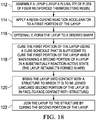
- Figures 18 broadly illustrates the steps of a method of fabricating a composite structure using partially cured parts.
- a composite ply layup is assembled comprising either dry fiber plies which are later infused with a thermoset resin, or by laying up a plurality of prepreg plies.
- the method includes ordering the plies 44 such that regions of plies 44 that remain uncured are located along an interfacial region 38.
- a catalyst 92 which functions as a resin curing accelerator 91 is applied to a first portion of the layup.
- the layup is formed to a desired shape.
- the first portion of the layup is cured using a cure schedule that is sufficient to cure the first portion of the layup while maintaining a second portion of the layup uncured, i.e. in a substantially reaction-active state.
- the cured portions of the layup maintain the shape of the layup without the need for tooling.
- the precured part is removed from the tooling and transported to a structure to which it is to be joined.
- the layup is brought into contact with a structure to which it is to be joined, in which the uncured second portions of the layup are placed in face-to-face contact with a structure which may be cured or uncured.
- the layup is joined to the structure by curing the second portion of the layup.
- Examples of the disclosure may find use in a variety of potential applications, particularly in the transportation industry, including for example, aerospace, marine, automotive applications and other application where pressurized fluid tubes, such as fuel systems and hydraulic systems in aircraft, may be used.
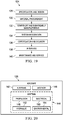
- Examples of the disclosure may be used in the context of an aircraft manufacturing and service method 124 as shown in Figure 19 and an aircraft 126 as shown in Figure 20 .
- Aircraft applications of the disclosed examples may include, for example, without limitation, a wide array of composite laminate parts that are joined together to form a structure.
- exemplary method 124 may include specification and design 128 of the aircraft 126 and material procurement 130.
- component and subassembly manufacturing 132 and system integration 134 of the aircraft 126 takes place. Thereafter, the aircraft 126 may go through certification and delivery 136 in order to be placed in service 138. While in service by a customer, the aircraft 126 is scheduled for routine maintenance and service 140, which may also include modification, reconfiguration, refurbishment, and so on.
- routine maintenance and service 140 which may also include modification, reconfiguration, refurbishment, and so on.
- the disclosed examples may be utilized in any one or more of steps 132, 134, 140, 142 and 146.
- Each of the processes of method 124 may be performed or carried out by a system integrator, a third party, and/or an operator (e.g., a customer).
- a system integrator may include without limitation any number of aircraft manufacturers and major-system subcontractors
- a third party may include without limitation any number of vendors, subcontractors, and suppliers
- an operator may be an airline, leasing company, military entity, service organization, and so on.
- the aircraft 126 produced by exemplary method 124 may include an airframe 142 with a plurality of systems 144 and an interior 146.
- high-level systems 144 include one or more of a propulsion system 148, an electrical system 150, a hydraulic system 152 and an environmental system 154. Any number of other systems may be included.
- an aerospace example is shown, the principles of the disclosure may be applied to other industries, such as the marine and automotive industries.
- Systems and methods embodied herein may be employed during any one or more of the stages of the production and service method 124.
- components or subassemblies corresponding to production process 132 may be fabricated or manufactured in a manner similar to components or subassemblies produced while the aircraft 126 is in service.
- one or more apparatus examples, method examples, or a combination thereof may be utilized during the production stages 132 and 134, for example, by substantially expediting assembly of or reducing the cost of an aircraft 116.
- apparatus examples, method examples, or a combination thereof may be utilized while the aircraft 126 is in service, for example and without limitation, to maintenance and service 140.
Landscapes
- Engineering & Computer Science (AREA)
- Mechanical Engineering (AREA)
- Chemical & Material Sciences (AREA)
- Health & Medical Sciences (AREA)
- Chemical Kinetics & Catalysis (AREA)
- Composite Materials (AREA)
- Physics & Mathematics (AREA)
- General Chemical & Material Sciences (AREA)
- Thermal Sciences (AREA)
- Oral & Maxillofacial Surgery (AREA)
- Manufacturing & Machinery (AREA)
- Organic Chemistry (AREA)
- Polymers & Plastics (AREA)
- Medicinal Chemistry (AREA)
- Materials Engineering (AREA)
- Moulding By Coating Moulds (AREA)
- Laminated Bodies (AREA)
- Reinforced Plastic Materials (AREA)
Abstract
Description
- The present disclosure generally relates to the fabrication of composite structures, and deals more particularly utilizing partially cured composite laminate parts.
- The term "composite", as used herein, may refer to a composite structure comprising fibers such as carbon fibers set in a matrix such as a thermoset resin.
- Composite laminate parts may be joined together by adhesive bonding, co-bonding or co-curing. In the case of adhesive bonding and co-bonding, at least one of the parts requires adequate surface preparation and proper adhesive selection in order to achieve the desired bonding quality. The need for surface preparation and elimination of surface contaminants increases manufacturing costs, and the use of bonding adhesives adds undesired weight to part assemblies. Manufacturing costs are also increased by the need to provide tooling for supporting the uncured parts during the joining process. These issues reduce the options available for efficient staging of manufacturing processes. It would therefore be desirable to provide more alternatives for assembly, joining and/or curing, and process sequencing.
- Therefore, it would be desirable to have a method and apparatus that take into account at least some of the issues discussed above, as well as other possible issues.
- The disclosure relates in general to manufacturing composite parts, and more specifically to joining composite laminate thermoset parts that are partially cured. A resin curing accelerator in the form of a catalyst is applied to portions of part layups that are to be precured. The catalyst accelerates curing of these portions at low cure temperatures, while leaving other portions of the parts uncured and therefore chemically reactive. Uncured portions of the parts can be brought into contact with each other and co-cured, while the cured portions of the parts provide the parts with stability. The catalyst can be strategically applied to certain regions of one or more plies before they are laid up, resulting in a part that has tailored curing.
- According to one example, a method is provided of making a composite structure. The method comprises assembling a layup, including laying up a plurality of plies of fiber reinforced thermoset resin, and applying a resin curing reaction accelerator to a first portion of the layup. The method further comprises curing the first portion of the layup using a cure schedule that is sufficient to cure the first portion of the layup while maintaining a second uncured portion of the layup uncured.
- According to another example, a method is provided of making a composite structure. The method comprises applying a resin curing accelerator to selected regions of fiber reinforced, thermoset resin plies, and assembling a layup including the thermoset resin plies to which the resin curing accelerator has been applied. The method further includes forming the layup to a desired shape, and producing a partially cured part by curing the selected regions of the thermoset plies having the resin curing accelerator applied thereto, while leaving other regions of the layup uncured. The method also includes placing the partially cured layup against a structure, and joining the partially cured part to the structure.
- According to still another example, a composite laminate part layup is provided, comprising a plurality of fiber reinforced, thermoset resin plies, wherein at least certain of the thermoset resin plies have a resin curing accelerator applied to at least a region thereof.
- One of the advantages of the disclosed examples is that the need for extensive surface preparation and bonding adhesives of parts to be joined may be eliminated. Another advantage is that tooling costs required for maintaining part shapes can be substantially reduced or eliminated. A further advantage is that specialized equipment is not required to achieve differential heating/cooling of different portions of the parts. Partial curing of parts can be performed using conventional equipment. Still another advantage is that partially cured composite laminate parts can be produced in which cured portions of parts support and maintain the shape of the uncured portions without the need for underlying support tooling or fixtures.
- The features, functions, and advantages can be achieved independently in various examples of the present disclosure or may be combined in yet other examples in which further details can be seen with reference to the following description and drawings.
- The novel features believed characteristic of the illustrative examples are set forth in the appended claims. The illustrative examples, however, as well as a preferred mode of use, further objectives and advantages thereof, will best be understood by reference to the following detailed description of an illustrative example of the present disclosure when read in conjunction with the accompanying drawings, wherein:
-
Figure 1 is an illustration of a diagrammatic view of an apparatus and method for producing composite plies having an acceleration catalyst strategically applied to selected regions of thereof. -
Figure 2 is an illustration of a plan view of several composite plies showing the regions to which the catalyst has been applied using the apparatus and method shown inFigure 1 . -
Figure 3 is an illustration of a diagrammatic view showing how plies with a strategically applied catalyst are processed to form a partially cured composite laminate part. -
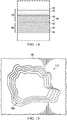
Figure 4 is an illustration of a side view of a composite laminate structure formed by two parts joined together along an interfacial region, wherein the parts have plies that are partially precured using a cure accelerator. -
Figure 5 is an illustration similar toFigure 4 , prior to full curing, wherein each of the parts has a cured portion and an uncured portion. -
Figure 6 is an illustration similar toFigure 5 but wherein only certain plies of the parts near the interfacial region are uncured. -
Figure 7 is an illustration similar toFigure 6 , but wherein only the plies of one of the parts near the interfacial region are uncured, and the parts are joined together along an adhesive bondline. -
Figure 8 is an illustration of the area designated as "FIG. 8 " inFigure 7 . -
Figure 9 is an illustration of a cross-sectional view of a hat stringer joined to a composite skin. -
Figure 10 is an illustration of the area designated as "FIG. 10 " inFigure 9 . -
Figure 11 is an illustration showing how plies having the catalyst strategically applied to certain regions thereof are used to form a hat stringer having uncured portions that can be co-cured or co-bonded to the composite skin shown inFigure 9 . -
Figure 12 is an illustration of a cross-sectional view of a partially cured blade stringer ready to be joined to a composite skin. -
Figure 13 illustration of the area designated as "FIG. 13" Figure 12 . -
Figure 14 is an illustration of the area designated as "FIG. 14 " inFigure 12 . -
Figure 15 is an illustration of a plan view of an aircraft skin having a scarfed area requiring rework. -
Figure 16 is an illustration of a sectional view of the scarfed area shown inFigure 15 , also showing a partially cured rework patch about to be applied thereto. -
Figure 17 is an illustration of a cross-sectional view of an aircraft skin having a partially cured rework patch positioned to be applied thereto, the plies of the patch being exploded to better reveal the cured and uncured portions thereof. -
Figure 18 is an illustration of a flow diagram of a method of joining composite parts. -
Figure 19 is an illustration of a flow diagram of aircraft production and service methodology. -
Figure 20 is an illustration of a block diagram of an aircraft. - Attention is now directed to
Figures 1 and 2 which diagrammatically illustrate an apparatus and method for strategically applying aresin curing accelerator 91 to selected regions of theplies 44 that allows partially curedparts portions 40, 42 (Figure 3 ) respectively. Theresin curing accelerator 91 comprises areaction catalyst 92 that causes the resin to which it is applied to cure at a temperature lower than the normal cure temperature and/or more quickly, compared to regions of theplies 44 to which thecatalyst 92 has not been applied. In other words, strategic application of thecatalyst 92 toregions 94 of theplies 44 allows differential curing of theparts -
Sheet material 74, which may comprise either a prepreg or dry fibers, is drawn from abulk supply reel 76 and guided through one ormore rollers 80 past acatalyst applicator 82. Thecatalyst applicator 82, which in the illustrated example is an automated applicator operated in accordance with a set of programmed instructions accessed by a programmedcontroller 88, applies asuitable reaction catalyst 92 to preselectedregions 94 of thesheet material 74, either by spraying, printing or using other techniques. Thecatalyst 92 is strategically applied to preselected regions of theplies 44 that are intended to be precured. Optionally, following the application of thecatalyst 92, acatalyst stabilizer 84 may be applied to thecatalyst 92 by astabilizer applicator 85 in order to stabilize thecatalyst 92. The catalyst stabilizer 84 functions to prevent potential degradation of thecatalyst 92.Sheet material 74 is then cut to the desired ply lengths by aply cutter 65 before being delivered onto a table 90 or other support where they may be picked up manually or by a pick-and-place machine (not shown) to form a ply layup. - While a largely automated process for strategic application of the
catalyst 92 to selected regions ofplies 44 has been described, a primarily manual process is possible. For example, plies 44 can be cut from bulk prepreg material, and thecatalyst 92 can then be applied by hand to the desired regions of theplies 44 using spraying, brushing or other manual techniques, following which theplies 44 can be manually stacked according to a desired ply schedule. Alternatively, theplies 44 can be manually transported and laid up by hand on a layup tool (not shown) that is used to shape theplies 44 prior to precuring in which the regions of theplies 44 having thecatalyst 92 applied thereto are cured at a temperature lower than the normal cure temperature. Alternately, thecatalyst 92 may be applied, either manually or under automatic control, to the individual plies 44 after theply 44 is placed on the layup tool 100 (Figure 11 ). -
Figure 2 illustrates fourtypical plies 44 showing thecatalyst 92 having been strategically applied only tocertain regions 94 of theplies 44 that are intended to be precured, while leaving the remainingregions 96 intended to remain uncured devoid of thecatalyst 92. - Attention is now directed to
Figure 3 which illustrates how theacceleration catalyst 92 can be strategically applied toplies 44 of either thermoset prepreg or dry fiber that is later impregnated with a thermoset resin to form a differentially curedpart uncured portions catalyst 92 should be suitable for the selected thermoset resin. For example, 4,4 0-methylene-bis 3-chloro-2,6-Diethylaniline can be used as the catalyst for cynate ester resins. In this example, thecatalyst 92 is applied on the left half of theplies 44, following which theplies 44 are stacked to form aply layup 102. At 103, thelayup 102 is heated according to a cure schedule that is sufficient to substantially cure theregions 94 that are to be precured but is insufficient to cure the remainingregions 96 that are to remain uncured and therefore chemically active. In the case of dry fiber plies 44, theplies 44 are infused with a thermoset resin, and then heated to a temperature that is sufficient to cure thoseregions 94 of theplies 44 to which thecatalyst 92 has been applied. - From the foregoing, it can be appreciated that differential curing of the
parts part part parts parts part part parts part - Referring first to
Figure 4 , acomposite structure 30 comprises twocomposite laminate parts area 36 at aninterfacial region 38 forming a lap joint. Theparts Figure 1 are joined together along aninterfacial region 38 either by co-bonding or co-curing. As will be discussed below in more detail, prior to being fully cured as shown inFigure 1 , at least one of theparts Figure 2 ) along theinterfacial region 38 that is achieved by differential curing of thepart Figure 2 ) to the piles of thepart Figure 11 ). -
Figure 5 illustrates one example of thecomposite structure 30 shown inFigure 4 in which the twoparts area 36 to form a lap joint 45, by co-curing the twoparts parts portion 40 and anuncured portion 42. As used herein, "cured portion" means that the cured portion has been cured to a degree that maintains the shape and stability of thepart portion 40 may be fully cured, while in other applications, the curedportion 40 may be cured to a greater degree than theuncured portion 42, but nevertheless cured to a point that maintains the overall shape and stability of thepart parts parts parts parts resin curing accelerator 91 applied thereto results in a partially curedpart part - In the example shown in
Figure 5 , theplies 44 of theparts thicknesses area 36 are uncured prior to being joined together and co-cured. Theportions 40 of theplies 44 outside of the overlappingarea 36 are precured prior to the joining process as a result of a curing accelerator 91 (seeFigure 1 ) having been applied thereto which allows theseportions 40 to be precured at a temperature lower than normal cure temperature, while maintainingother portions 42 uncured. Theuncured portions 42 of theparts interfacial region 38. When subjected to a full cure process explained later, theuncured portions 42 of the twoparts interfacial region 38. - Referring now to
Figure 6 , in this example, only a few of theplies 44a within thethicknesses interfacial region 38 within the overlappingarea 36 are uncured. The curedportions 40 may be cured at a lower-than-normal cure temperature due to theresin curing accelerator 91 having been applied thereto, while thoseplies 44a along theinterfacial region 38 which do not have an application of theresin curing accelerator 91 remain uncured. From the foregoing, it may be appreciated that strategic application of theresin curing accelerator 91 allows pre-curing of any selected region e.g. overlappingarea 36 of anyply 44 within thethickness part plies 44a within the same region remain uncured. Thus, it is apparent that the twoparts uncured plies 44a along theinterfacial region 38, while the curedportions 40 that have been precured using theresin curing accelerator 91 maintain the shapes of theparts portions 40, which are aligned with and positioned above theuncured portions 40, therefore provide stability and support for theuncured portions 40, without the need for supporting tooling. -
Figures 7 and8 illustrate another example in which the twoparts adhesive bondline 50 by co-bonding. In this example, anuncured portion 42 ofpart 32 comprising severaluncured plies 44a along theinterfacial region 38 are bonded topart 34 of which all plies 44 have been precured. The regions of theplies 44 that are stacked above theuncured plies 44a have had theresin curing accelerator 91 applied thereto, allowing them to be precured at a temperature that is lower than the normal cure temperature of the thermoset resin. Once the bonding adhesive is applied to one or both of theparts parts part 32 with the adhesive along theadhesive bondline 50. - Attention is now directed to
Figures 9 and 10 which illustrate a compositelaminate hat stringer 54 that is joined to acomposite laminate skin 56. Thehat stringer 54 comprises a top 58,webs 60 and outwardly extendingflanges 62. Thehat stringer 54 includes a curedportion 40, and anuncured portion 42 comprisinguncured plies 44a on thebottoms 62a of theflanges 62. As best seen inFigure 7 , thoseplies 44 near the top offlanges 62 have been precured at a lower than normal cure temperature according to a first cure schedule as a result of having theresin curing accelerator 91 applied thereto, while theplies 44 near theinterfacial region 38 at the bottom 62a that do not have an appliedresin curing accelerator 91, remain uncured and are subsequently cured at the higher, normal cure temperature of the resin according to a second cure schedule. Thecomposite skin 56 is also a partially cured structure having curedportions 40 anduncured portions 42. Theuncured portions 42 of theskin 56 are located along theinterfacial region 38, facing theuncured portions 42 of theflanges 62. In this example, thebottoms 62a offlanges 62 are cocured to theuncured portion 42 of theskin 56. In other examples, theskin 56 may be fully cured, in which case theuncured plies 44a on thebottoms 62a of theflanges 62 may be co-bonded to theskin 56. - Reference is now made to
Figure 11 which illustrates how the partially curedhat stringer 54 ofFigure 9 can be produced using the process shown inFigure 1 to strategically apply thecatalyst 92 toregions 94 of theplies 44 that are to be precured, while leavingother regions 96 uncured. A top plan view on the left side ofFigure 11 depicts threeplies catalyst 92 has been strategically applied. Only three plies are shown for sake of simplicity of description however in practical applications atypical hat stringer 54 may comprise a greater number ofplies 44. In this example, ply 44a is a bottom ply, 44c is a top ply and ply 44b is an intermediate ply positioned betweenplies Catalyst 92 is applied only to thecentral region 94 ofplies webs 60 of thestringer 54. Thecatalyst 92 is also applied only to theregions 94 at the left and right edges ofply 44c which correspond to theflanges 62. - The
plies suitable tool 100 having a cross-sectional shape corresponding to a completedstringer 54. In one example, theplies tool 100 where it is formed down onto, heated and consolidated using autoclave or out of autoclave processing. In another example, theplies tool 100. The ply layup on thetool 100 is then heated and consolidated in an autoclave, pressclave or oven, according to a first cure schedule that is sufficient to cure thoseregions 94 that are to be precured, i.e., those portions of theplies hat stringer 54 is maintained as a result of the stiffness of theprecured regions 94, while theuncured regions 96 of the bottom andintermediate plies - Following the forming and pre-curing process described above, the
stringer 54 is removed from thetool 100 and transferred to the skin 56 (Figure 9 ) where thebottoms 62a offlanges 62 are brought into contact and placed against theskin 56. Thebottoms 62a of theflanges 62 can be co-cured or co-bonded with thecomposite skin 56 or other composite structure, using a second cure schedule. Curing according the second cure schedule results in full curing of thebottoms 62a of theflanges 62 as well as adhesive that may be used to cobond thestringer 54 and theskin 56. Although not shown in the Figures, it may be possible to tack certain of theplies 44 together by applying thecatalyst 92 to regions of theplies 44 that are to be tacked together. Using this technique, certain of theplies 44 may be tacked together, while otheruncured plies 44 are allowed to slip relative to theother plies 44 during the forming. - Referring now to
Figures 12, 13 and14 , ablade stringer 64 comprises ablade 68 and a pair of flanges 69 joined to acomposite skin 56. Theblade stringer 64 includes a pair of L-shapedmembers 66 joined together to form a preassembled part before being joined to theskin 56. Each of the L-shapedmembers 66 includes aflange section 70 and ablade section 72. Each of theblade sections 72 includesuncured portions 42 along aninterfacial region 38 between the twoblade sections 72. More particularly, theuncured portions 42 of the twoblade sections 72 are joined together by co-curing. Referring particularly toFigures 8 and 10 , the uncured portions 42a of theflange sections 70 compriseuncured plies 42 along theinterfacial region 38 that are co-bonded to the fully cured plies 44 of theskin 56 along anadhesive bondline 50. - Thus, from the foregoing, it can be appreciated that the L-shaped
members 66 each comprise cured anduncured portions flanges sections 70 are joined to theskin 56 by co-bonding. As in previous examples discussed above, cured anduncured portions resin curing accelerator 91 to only selected regions of selected plies 44 that are to be precured. A two-step curing process is then used in which regions of theplies 44 having theresin curing accelerator 91 are cured at a lower-than-normal cure temperature, and the remaining uncured regions of theplies 44 without the curingaccelerator 91 are subsequently cured at the normal, full cure temperature. - The
plies suitable tool 100 having a cross-sectional shape corresponding to a completedstringer 54. The ply layup is then heated to a temperature that is sufficient to cure thoseregions 94 that are to be precured, i.e., those portions of theplies hat stringer 54 is maintained as a result of the stiffness and rigidity of theprecured regions 94, while theuncured regions 96 of the bottom andintermediate plies bottoms 62a of theflanges 62 can be co-cured or co-bonded with an underlying composite part, such as a composite skin 56 (not shown inFigure 14 ). -
Figures 15 and16 illustrate the use of theacceleration catalyst 92 to produce a partially curedcomposite laminate patch 110 that may be used in the field to rework acomposite skin 56 of an aircraft. Thecomposite skin 56 has a scarfed depression within the area requiring rework. Thepatch 110 comprises a plurality of composite plies 44, at least certain of which are partially precured. In the illustrated example, the outer extremities of a number of theplies 44 compriseuncured portions 42 while the remainder of those plies comprise curedportions 40. Thebottom ply 44a of thepatch 110 remains entirely uncured. In this example, it can be appreciated that the entire area of thepatch 110 that is to be joined to theskin 56 is uncured. Theuncured portions 42 of thepatch 110 are co-bonded to the curedskin 56 using a suitable bonding adhesive. Following placement of thepatch 110 on theskin 56, thepatch 110 is heated to a temperature sufficient to fully cure theuncured portions 42. Theuncured portions 42 are supported by the rigid curedportions 40. -
Figure 17 illustrates a partially curedrework patch 110 that can be applied to the surface of theskin 56 that is not scarfed. In this example, the partially curedpatch 110 includes twobottom plies 44a that are entirely uncured, twointermediate plies 44b that are partially cured, and atop ply 44c that is fully cured. The fully cured and partially curedplies rework patch 110 even though thepatch 110 includesuncured portions 40. - Attention is now directed to
Figures 18 which broadly illustrates the steps of a method of fabricating a composite structure using partially cured parts. At 112, a composite ply layup is assembled comprising either dry fiber plies which are later infused with a thermoset resin, or by laying up a plurality of prepreg plies. The method includes ordering theplies 44 such that regions ofplies 44 that remain uncured are located along aninterfacial region 38. At 114, acatalyst 92 which functions as aresin curing accelerator 91 is applied to a first portion of the layup. At 116, optionally, the layup is formed to a desired shape. At 118, the first portion of the layup is cured using a cure schedule that is sufficient to cure the first portion of the layup while maintaining a second portion of the layup uncured, i.e. in a substantially reaction-active state. The cured portions of the layup maintain the shape of the layup without the need for tooling. In those applications where the layup has been formed against tooling during precuring, the precured part is removed from the tooling and transported to a structure to which it is to be joined. At 120, the layup is brought into contact with a structure to which it is to be joined, in which the uncured second portions of the layup are placed in face-to-face contact with a structure which may be cured or uncured. At 122, the layup is joined to the structure by curing the second portion of the layup. - Examples of the disclosure may find use in a variety of potential applications, particularly in the transportation industry, including for example, aerospace, marine, automotive applications and other application where pressurized fluid tubes, such as fuel systems and hydraulic systems in aircraft, may be used. Thus, referring now to
Figures 19 and 20 , examples of the disclosure may be used in the context of an aircraft manufacturing andservice method 124 as shown inFigure 19 and anaircraft 126 as shown inFigure 20 . Aircraft applications of the disclosed examples may include, for example, without limitation, a wide array of composite laminate parts that are joined together to form a structure. During pre-production,exemplary method 124 may include specification anddesign 128 of theaircraft 126 andmaterial procurement 130. During production, component andsubassembly manufacturing 132 andsystem integration 134 of theaircraft 126 takes place. Thereafter, theaircraft 126 may go through certification anddelivery 136 in order to be placed inservice 138. While in service by a customer, theaircraft 126 is scheduled for routine maintenance andservice 140, which may also include modification, reconfiguration, refurbishment, and so on. The disclosed examples may be utilized in any one or more ofsteps - Each of the processes of
method 124 may be performed or carried out by a system integrator, a third party, and/or an operator (e.g., a customer). For the purposes of this description, a system integrator may include without limitation any number of aircraft manufacturers and major-system subcontractors; a third party may include without limitation any number of vendors, subcontractors, and suppliers; and an operator may be an airline, leasing company, military entity, service organization, and so on. - As shown in
Figure 19 , theaircraft 126 produced byexemplary method 124 may include anairframe 142 with a plurality ofsystems 144 and an interior 146. Examples of high-level systems 144 include one or more of apropulsion system 148, anelectrical system 150, ahydraulic system 152 and anenvironmental system 154. Any number of other systems may be included. Although an aerospace example is shown, the principles of the disclosure may be applied to other industries, such as the marine and automotive industries. - Systems and methods embodied herein may be employed during any one or more of the stages of the production and
service method 124. For example, components or subassemblies corresponding toproduction process 132 may be fabricated or manufactured in a manner similar to components or subassemblies produced while theaircraft 126 is in service. Also, one or more apparatus examples, method examples, or a combination thereof may be utilized during the production stages 132 and 134, for example, by substantially expediting assembly of or reducing the cost of anaircraft 116. Similarly, one or more of apparatus examples, method examples, or a combination thereof may be utilized while theaircraft 126 is in service, for example and without limitation, to maintenance andservice 140. - The present invention is also referred to in the following clauses which are not to be confused with the claims.
- A1. A method of making a composite structure (30), comprising: assembling a layup (102), including laying up a plurality of plies (44) of fiber reinforced thermoset resin; applying a resin curing accelerator (91, 92) to a first portion (40) of the layup (102); and, curing the first portion (40) of the layup (102) using a cure schedule that is sufficient to cure the first portion (40) of the layup (102) while maintaining a second uncured portion (42) of the layup (102) uncured.
- A2. The method of clause A1, further comprising: curing the second uncured portion (41) of the layup (102) according to a cure schedule different from the cure schedule used to cure the first portion (40) of the layup (102).
- A3. The method of clause A2, wherein: curing the first portion (40) of the layup (102) includes heating the layup (102) to a first temperature, and curing the second uncured portion (42) of the layup (102) includes heating the layup (102) to a second temperature higher than the first temperature.
- A4. The method of any of clauses A1 to A3, wherein the first portion (40) of the layup (102) includes at least one exposed ply (44a) of the layup (102) located along an interfacial region (38) adapted to be joined to a structure (32, 34).
- A5. The method of any of clauses A1 to A4, wherein assembling the layup (102) includes arranging the plies (44) such that at least a section (44a) of the first portion (40) of the layup (102) is aligned with at least a section of the second portion (42) of the layup (102).
- A6. The method of any of clauses A1 to A5, further comprising the step of: forming the layup (102) to a desired shape before curing the second uncured portion (42) of the layup (102).
- A7. The method of any of clauses A1 to A6, further comprising: applying a stabilizer (84) to the curing accelerator (91, 92).
- B1. A method of making a composite structure (30), comprising: applying a resin curing accelerator (91, 92) to selected regions (94) of fiber reinforced, thermoset resin plies (44); assembling a layup (102) including the thermoset resin plies (44) to which the resin curing accelerator (91, 92) has been applied; and forming the layup (102) to a desired shape.
- B2. The method of clause B1, wherein: assembling the layup (102) includes laying up the thermoset resin plies (44) on a forming tool (100), and forming the layup (102) to the desired shape includes forming the thermoset resin plies (44) on the forming tool (100).
- B3. The method of clause B1 or B2, wherein applying the resin curing accelerator (91, 92) is performed by an automated applicator (82) according to programmed instructions.
- B4. The method of any of clauses B1 to B3, further comprising: reducing potential degradation of the resin curing accelerator (91, 92) by applying a stabilizer (84) to the resin curing accelerator (91, 92).
- B5. The method of any of clauses B1 to B4, further comprising: producing a partially cured part (32, 34) by curing the selected regions (94) of the thermoset plies (44) having the resin curing accelerator (91, 92) applied thereto, while leaving other regions (96) of the layup (102) uncured; placing the partially cured part (32, 34) against a structure (32, 34); and joining the partially cured part (32, 34) to the structure (32, 34).
- B6. The method of clauseB5, wherein joining the partially cured part (32, 34) to the structure (32, 34) is performed by co-bonding or co-curing.
- B7. The method of clauseB5 or B6, wherein applying the resin curing accelerator (91, 92) includes selecting regions (94) of the thermoset plies (44) which, when fully cured, maintain the desired shape of the partially cured part (32, 34) .
- B8. The method of any of clauses B5 to B7, further comprising: arranging the plies (44) of the layup (102) such that the other regions (96) of the layup (102) that are left uncured are located along an interfacial region (30) between the partially cured part (32, 34) and the structure (32, 34) to which the partially cured part (32, 34) is to be joined.
- B9. The method of any of clauses B1 to B8, wherein assembling the layup (102) includes arranging the plies (44) such that the selected regions (94) to which the resin curing accelerator (91, 92) is applied are aligned within the layup (102) with other regions (96) of the layup (102) not having the resin curing accelerator (91, 92) applied thereto.
- C1. A composite laminate part layup (102), comprising: a plurality of fiber reinforced, thermoset resin plies (44), wherein at least certain of the thermoset resin plies have a resin curing accelerator (91, 92) applied to at least a region (94) thereof.
- C2. The composite laminate part layup (102) of clause C1, wherein: the resin curing accelerator (91, 92) is applied fully over the certain of the thermoset resin plies (44).
- C3. The composite laminate part layup (102) of clause C1 or C2, wherein all of the thermoset resin plies (44) having the resin curing accelerator (91, 92) applied to a region (94) thereof.
- C4. The composite laminate part layup (102) of any of clauses C1 to C3, wherein: the layup (102) includes an interfacial region (38) configured to be joined to a structure (32, 34), and the thermoset plies (44) of the layup (102) along the interfacial region (38) are devoid of the resin curing accelerator (91, 92).
- C5. The composite laminate part layup (102) of any of clauses C1 to C4, wherein the thermoset resin is epoxy resin, cynate ester resin, polyurethane resin or phenolic resin.
- D1. A method of making a composite structure, comprising: applying a resin curing accelerator to selected regions of fiber reinforced, thermoset resin plies; assembling a layup including the thermoset resin plies to which the resin curing accelerator has been applied; forming the layup to a desired shape; producing a partially cured part by curing the selected regions of the thermoset plies having the resin curing accelerator applied thereto, while leaving other regions of the layup uncured; placing the partially cured part against a structure; and joining the partially cured part to the structure.
- D2. The method of clause D1, wherein: assembling the layup includes laying up the thermoset resin plies on a forming tool, and forming the layup to the desired shape includes forming the thermoset resin plies on the forming tool.
- D3. The method of clause D1 or D2, wherein applying the resin curing accelerator is performed by an automated applicator according to programmed instructions.
- D4. The method of any of clauses D1 to D3, further comprising: reducing potential degradation of the resin curing accelerator by applying a stabilizer to the resin curing accelerator.
- D5. The method of any of clauses D1 to D4, wherein applying the resin curing accelerator includes selecting regions of the thermoset plies which, when fully cured, maintain the desired shape of the partially cured part.
- D6. The method of any of clauses D1 to D5, further comprising: arranging the plies of the layup such that the other regions of the layup that are left uncured are located along an interfacial region between the partially cured part and the structure to which the partially cured part is to be joined.
- D7. The method of any of clauses D1 to D6, wherein joining the partially cured part to the structure is performed by co-bonding or co-curing.
- D8. The method of any of clauses D1 to D7, wherein assembling the layup includes arranging the plies such that the selected regions to which the resin curing accelerator is applied are aligned within the layup with the other regions of the layup that are uncured.
- E1. A composite structure formed by the method of any of clauses A1 to A7, B1 to B9 or D1 to D8 wherein, optionally, the composite structure (30) is an aircraft part.
- The description of the different illustrative examples has been presented for purposes of illustration and description, and is not intended to be exhaustive or limited to the examples in the form disclosed. Many modifications and variations will be apparent to those of ordinary skill in the art. Further, different illustrative examples may provide different advantages as compared to other illustrative examples. The example or examples selected are chosen and described in order to best explain the principles of the examples, the practical application, and to enable others of ordinary skill in the art to understand the disclosure for various examples with various modifications as are suited to the particular use contemplated.
Claims (15)
- A method of making a composite structure (30), comprising:applying a resin curing accelerator (91, 92) to selected regions (94) of fiber reinforced, thermoset resin plies (44);assembling a layup (102) including the thermoset resin plies (44) to which the resin curing accelerator (91, 92) has been applied; andforming the layup (102) to a desired shape.
- The method of claim 1, wherein:assembling the layup (102) includes laying up the thermoset resin plies (44) on a forming tool (100), andforming the layup (102) to the desired shape includes forming the thermoset resin plies (44) on the forming tool (100) .
- The method of claim 1 or 2, wherein applying the resin curing accelerator (91, 92) is performed by an automated applicator (82) according to programmed instructions.
- The method of any preceding claim, further comprising:reducing potential degradation of the resin curing accelerator (91, 92) by applying a stabilizer (84) to the resin curing accelerator (91, 92).
- The method of any preceding claim, further comprising:producing a partially cured part (32, 34) by curing the selected regions (94) of the thermoset plies (44) having the resin curing accelerator (91, 92) applied thereto, while leaving other regions (96) of the layup (102) uncured;placing the partially cured part (32, 34) against a structure (32, 34); andjoining the partially cured part (32, 34) to the structure (32, 34).
- The method of claim 5, wherein joining the partially cured part (32, 34) to the structure (32, 34) is performed co-bonding or co-curing.
- The method of claim 5 or 6, wherein applying the resin curing accelerator (91, 92) includes selecting regions (94) of the thermoset plies (44) which, when fully cured, maintain the desired shape of the partially cured part (32, 34).
- The method of any of claims 5 to 7, further comprising:arranging the plies (44) of the layup (102) such that the other regions (96) of the layup (102) that are left uncured are located along an interfacial region (30) between the partially cured part (32, 34) and the structure (32, 34) to which the partially cured part (32, 34) is to be joined.
- The method of any preceding claim, wherein assembling the layup (102) includes arranging the plies (44) such that the selected regions (94) to which the resin curing accelerator (91, 92) is applied are aligned within the layup (102) with other regions (96) of the layup (102) not having the resin curing accelerator (91, 92) applied thereto.
- A composite structure (30) formed by the method of any preceding claim wherein, optionally, the composite structure (30) is an aircraft part.
- A composite laminate part layup (102), comprising:a plurality of fiber reinforced, thermoset resin plies (44),wherein at least certain of the thermoset resin plies have a resin curing accelerator (91, 92) applied to at least a region (94) thereof.
- The composite laminate part layup (102) of claim 11, wherein:the resin curing accelerator (91, 92) is applied fully over the certain of the thermoset resin plies (44).
- The composite laminate part layup (102) of claim 11, wherein all of the thermoset resin plies (44) having the resin curing accelerator (91, 92) applied to a region (94) thereof.
- The composite laminate part layup (102) of claim 11,
wherein:the layup (102) includes an interfacial region (38) configured to be joined to a structure (32, 34), andthe thermoset plies (44) of the layup (102) along the interfacial region (38) are devoid of the resin curing accelerator (91, 92). - The composite laminate part layup (102) of claim 11, wherein the thermoset resin is epoxy resin, cynate ester resin, polyurethane resin or phenolic resin.
Applications Claiming Priority (1)
| Application Number | Priority Date | Filing Date | Title |
|---|---|---|---|
| US15/713,655 US10549489B2 (en) | 2017-09-24 | 2017-09-24 | Partial curing of thermoset composites |
Publications (2)
| Publication Number | Publication Date |
|---|---|
| EP3466632A1 true EP3466632A1 (en) | 2019-04-10 |
| EP3466632B1 EP3466632B1 (en) | 2025-07-02 |
Family
ID=63556247
Family Applications (1)
| Application Number | Title | Priority Date | Filing Date |
|---|---|---|---|
| EP18193550.3A Active EP3466632B1 (en) | 2017-09-24 | 2018-09-10 | Partial curing of thermoset composites |
Country Status (7)
| Country | Link |
|---|---|
| US (2) | US10549489B2 (en) |
| EP (1) | EP3466632B1 (en) |
| KR (1) | KR102535014B1 (en) |
| CN (1) | CN109551777B (en) |
| ES (1) | ES3038879T3 (en) |
| PT (1) | PT3466632T (en) |
| RU (1) | RU2768684C2 (en) |
Cited By (1)
| Publication number | Priority date | Publication date | Assignee | Title |
|---|---|---|---|---|
| EP4684947A3 (en) * | 2024-07-25 | 2026-03-18 | Airbus (S.A.S.) | Tape structure of a tape for use in manufacturing a composite structure, automated fibre placement (afp) device, automated fibre placement (afp) method and composite structure |
Families Citing this family (9)
| Publication number | Priority date | Publication date | Assignee | Title |
|---|---|---|---|---|
| US10549489B2 (en) | 2017-09-24 | 2020-02-04 | The Boeing Company | Partial curing of thermoset composites |
| US11472140B2 (en) * | 2018-07-12 | 2022-10-18 | The Boeing Company | Composite structure through-hole repair methods |
| US11198249B2 (en) * | 2018-07-30 | 2021-12-14 | General Electric Company | Method of joining additively manufactured components |
| DE102019005913A1 (en) * | 2019-08-22 | 2021-02-25 | Siempelkamp Maschinen- Und Anlagenbau Gmbh | Method and device for manufacturing a component from a fiber composite material |
| US12252969B2 (en) | 2019-12-19 | 2025-03-18 | Schlumberger Technology Corporation | Undercured stator for mud motor |
| CN114945626B (en) * | 2020-01-31 | 2024-05-28 | 东丽株式会社 | Composite prepreg, preform using the same, fiber-reinforced composite material joint, and method for producing the same |
| US20230152061A1 (en) * | 2020-02-06 | 2023-05-18 | University Of Washington | Fiber composites having strength and flexibility, systems, and methods thereof |
| CN113324812A (en) * | 2021-05-24 | 2021-08-31 | 浙江大学 | Weak-adhesion controllable defect test piece and manufacturing technology and nondestructive testing method thereof |
| EP4650155A1 (en) * | 2024-05-17 | 2025-11-19 | Airbus S.A.S. | Fibre composite material, a method of manufacturing a composite structure and composite structure |
Citations (4)
| Publication number | Priority date | Publication date | Assignee | Title |
|---|---|---|---|---|
| US5176949A (en) * | 1988-10-28 | 1993-01-05 | Brochier S.A. | Textile reinforcements for composite materials and method of manufacturing thereof |
| US20080011377A1 (en) * | 2006-07-14 | 2008-01-17 | Veritas Ag | Flexible hose |
| US20100124659A1 (en) * | 2008-11-19 | 2010-05-20 | The Boeing Company | Staged cocuring of composite structures |
| WO2017055920A1 (en) * | 2015-09-28 | 2017-04-06 | Toray Industries, Inc. | Prepreg with variable cure rate resin compositions |
Family Cites Families (16)
| Publication number | Priority date | Publication date | Assignee | Title |
|---|---|---|---|---|
| US2606880A (en) | 1949-04-26 | 1952-08-12 | American Viscose Corp | Acid-curing thermosetting resins containing esters of oxanilic acid as latent catalysts therefor |
| US6284089B1 (en) | 1997-12-23 | 2001-09-04 | The Boeing Company | Thermoplastic seam welds |
| WO2008012378A1 (en) * | 2006-07-28 | 2008-01-31 | Airbus España, S.L. | Method for producing pieces of compound materials with two curing cycles |
| US8752293B2 (en) | 2007-12-07 | 2014-06-17 | The Boeing Company | Method of fabricating structures using composite modules and structures made thereby |
| DE102008029056A1 (en) | 2008-06-18 | 2009-12-31 | GKN Aerospace Services Limited, East Cowes | Manufacturing method of fiber reinforced composite components with microwaves |
| US20100116938A1 (en) | 2008-11-13 | 2010-05-13 | Kline William T | Method and apparatus for joining composite structural members and structural members made thereby |
| US8307872B2 (en) | 2008-11-13 | 2012-11-13 | The Boeing Company | Apparatus for curing a composite structural member |
| NL2006848C2 (en) * | 2011-05-25 | 2012-11-27 | Univ Delft Technology | Method for bonding a thermoplastic polymer to a thermosetting polymer component. |
| RU2618055C2 (en) * | 2012-11-26 | 2017-05-02 | Сайтек Индастриз Инк. | Composite materials bonding |
| BR112015014928B1 (en) * | 2012-12-21 | 2021-03-30 | Cytec Industries Inc. | CURABLE COMPOSITE MATERIAL AND METHODS FOR MANUFACTURING A CURABLE COMPOSITE MATERIAL AND FOR MANUFACTURING A CURABLE COMPOSITE PIECE |
| US9394881B2 (en) | 2013-05-29 | 2016-07-19 | Siemens Aktiengesellschaft | Wind turbine blade and method of fabricating a wind turbine blade |
| ES2861148T3 (en) * | 2013-12-13 | 2021-10-05 | Airbus Operations Sl | Manufacturing method of partially cured composite material components |
| NL2014306B1 (en) * | 2015-02-18 | 2016-10-13 | Mocs Beheer B V | Thermosetting composite article and method for producing the same. |
| US9731453B2 (en) * | 2015-03-04 | 2017-08-15 | The Boeing Company | Co-curing process for the joining of composite structures |
| GB201515715D0 (en) * | 2015-09-04 | 2015-10-21 | Gurit Uk Ltd | Prepregs and production of composite material using prepregs |
| US10549489B2 (en) | 2017-09-24 | 2020-02-04 | The Boeing Company | Partial curing of thermoset composites |
-
2017
- 2017-09-24 US US15/713,655 patent/US10549489B2/en active Active
-
2018
- 2018-06-18 RU RU2018122069A patent/RU2768684C2/en active
- 2018-07-16 CN CN201810778065.7A patent/CN109551777B/en active Active
- 2018-08-02 KR KR1020180090295A patent/KR102535014B1/en active Active
- 2018-09-10 ES ES18193550T patent/ES3038879T3/en active Active
- 2018-09-10 PT PT181935503T patent/PT3466632T/en unknown
- 2018-09-10 EP EP18193550.3A patent/EP3466632B1/en active Active
-
2019
- 2019-12-18 US US16/719,903 patent/US11220069B2/en active Active
Patent Citations (4)
| Publication number | Priority date | Publication date | Assignee | Title |
|---|---|---|---|---|
| US5176949A (en) * | 1988-10-28 | 1993-01-05 | Brochier S.A. | Textile reinforcements for composite materials and method of manufacturing thereof |
| US20080011377A1 (en) * | 2006-07-14 | 2008-01-17 | Veritas Ag | Flexible hose |
| US20100124659A1 (en) * | 2008-11-19 | 2010-05-20 | The Boeing Company | Staged cocuring of composite structures |
| WO2017055920A1 (en) * | 2015-09-28 | 2017-04-06 | Toray Industries, Inc. | Prepreg with variable cure rate resin compositions |
Cited By (1)
| Publication number | Priority date | Publication date | Assignee | Title |
|---|---|---|---|---|
| EP4684947A3 (en) * | 2024-07-25 | 2026-03-18 | Airbus (S.A.S.) | Tape structure of a tape for use in manufacturing a composite structure, automated fibre placement (afp) device, automated fibre placement (afp) method and composite structure |
Also Published As
| Publication number | Publication date |
|---|---|
| RU2018122069A3 (en) | 2021-09-20 |
| US10549489B2 (en) | 2020-02-04 |
| US11220069B2 (en) | 2022-01-11 |
| US20190091947A1 (en) | 2019-03-28 |
| PT3466632T (en) | 2025-08-20 |
| CN109551777A (en) | 2019-04-02 |
| EP3466632B1 (en) | 2025-07-02 |
| RU2018122069A (en) | 2019-12-18 |
| ES3038879T3 (en) | 2025-10-15 |
| CN109551777B (en) | 2022-10-28 |
| KR102535014B1 (en) | 2023-05-19 |
| KR20190035482A (en) | 2019-04-03 |
| US20200156330A1 (en) | 2020-05-21 |
| RU2768684C2 (en) | 2022-03-24 |
Similar Documents
| Publication | Publication Date | Title |
|---|---|---|
| US11220069B2 (en) | Composite laminate structures | |
| AU2020201610B2 (en) | Fabrication of composite laminates using temporarily stitched preforms | |
| US9096305B2 (en) | Curved composite frames and method of making the same | |
| US10293572B2 (en) | Method for joining sandwich truss core panels and composite structures produced therefrom | |
| CA2857783C (en) | Laminated composite radius filler with geometric shaped filler element and method of forming the same | |
| US9387657B2 (en) | Method of fabricating a curved composite structure using composite prepreg tape | |
| US11007726B2 (en) | Forming composite features using steered discontinuous fiber pre-preg | |
| EP2764987B1 (en) | Method and system of making composite structures having gap fillers with chopped fiber material | |
| US8551380B2 (en) | Method of laying up prepreg plies on contoured tools using a deformable carrier film | |
| US9302759B2 (en) | Flexible truss frame and method of making the same | |
| US9701067B2 (en) | Method of laying up prepreg plies on contoured tools using a deformable carrier film | |
| EP2602094B1 (en) | Method of fabricating composite laminate structures allowing ply slippage during forming | |
| JP2016172437A (en) | Co-hardening process for joining composite material structure | |
| EP3919370B1 (en) | Aircraft stringers having cfrp material reinforced flanges |
Legal Events
| Date | Code | Title | Description |
|---|---|---|---|
| PUAI | Public reference made under article 153(3) epc to a published international application that has entered the european phase |
Free format text: ORIGINAL CODE: 0009012 |
|
| STAA | Information on the status of an ep patent application or granted ep patent |
Free format text: STATUS: REQUEST FOR EXAMINATION WAS MADE |
|
| 17P | Request for examination filed |
Effective date: 20180910 |
|
| AK | Designated contracting states |
Kind code of ref document: A1 Designated state(s): AL AT BE BG CH CY CZ DE DK EE ES FI FR GB GR HR HU IE IS IT LI LT LU LV MC MK MT NL NO PL PT RO RS SE SI SK SM TR |
|
| AX | Request for extension of the european patent |
Extension state: BA ME |
|
| STAA | Information on the status of an ep patent application or granted ep patent |
Free format text: STATUS: EXAMINATION IS IN PROGRESS |
|
| 17Q | First examination report despatched |
Effective date: 20220210 |
|
| RAP3 | Party data changed (applicant data changed or rights of an application transferred) |
Owner name: THE BOEING COMPANY |
|
| GRAP | Despatch of communication of intention to grant a patent |
Free format text: ORIGINAL CODE: EPIDOSNIGR1 |
|
| STAA | Information on the status of an ep patent application or granted ep patent |
Free format text: STATUS: GRANT OF PATENT IS INTENDED |
|
| RIC1 | Information provided on ipc code assigned before grant |
Ipc: B29L 31/30 20060101ALN20241004BHEP Ipc: B29K 105/24 20060101ALN20241004BHEP Ipc: B29C 73/10 20060101ALN20241004BHEP Ipc: B29C 65/48 20060101ALI20241004BHEP Ipc: B29C 65/02 20060101ALI20241004BHEP Ipc: B29C 65/00 20060101ALI20241004BHEP Ipc: B29C 70/30 20060101ALI20241004BHEP Ipc: B29C 35/02 20060101AFI20241004BHEP |
|
| INTG | Intention to grant announced |
Effective date: 20241022 |
|
| P01 | Opt-out of the competence of the unified patent court (upc) registered |
Free format text: CASE NUMBER: APP_61902/2024 Effective date: 20241119 |
|
| GRAJ | Information related to disapproval of communication of intention to grant by the applicant or resumption of examination proceedings by the epo deleted |
Free format text: ORIGINAL CODE: EPIDOSDIGR1 |
|
| STAA | Information on the status of an ep patent application or granted ep patent |
Free format text: STATUS: EXAMINATION IS IN PROGRESS |
|
| GRAP | Despatch of communication of intention to grant a patent |
Free format text: ORIGINAL CODE: EPIDOSNIGR1 |
|
| STAA | Information on the status of an ep patent application or granted ep patent |
Free format text: STATUS: GRANT OF PATENT IS INTENDED |
|
| INTC | Intention to grant announced (deleted) | ||
| RIC1 | Information provided on ipc code assigned before grant |
Ipc: B29L 31/30 20060101ALN20250121BHEP Ipc: B29K 105/24 20060101ALN20250121BHEP Ipc: B29C 73/10 20060101ALN20250121BHEP Ipc: B29C 65/48 20060101ALI20250121BHEP Ipc: B29C 65/02 20060101ALI20250121BHEP Ipc: B29C 65/00 20060101ALI20250121BHEP Ipc: B29C 70/30 20060101ALI20250121BHEP Ipc: B29C 35/02 20060101AFI20250121BHEP |
|
| RIC1 | Information provided on ipc code assigned before grant |
Ipc: B29L 31/30 20060101ALN20250129BHEP Ipc: B29K 105/24 20060101ALN20250129BHEP Ipc: B29C 73/10 20060101ALN20250129BHEP Ipc: B29C 65/48 20060101ALI20250129BHEP Ipc: B29C 65/02 20060101ALI20250129BHEP Ipc: B29C 65/00 20060101ALI20250129BHEP Ipc: B29C 70/30 20060101ALI20250129BHEP Ipc: B29C 35/02 20060101AFI20250129BHEP |
|
| INTG | Intention to grant announced |
Effective date: 20250210 |
|
| GRAS | Grant fee paid |
Free format text: ORIGINAL CODE: EPIDOSNIGR3 |
|
| GRAA | (expected) grant |
Free format text: ORIGINAL CODE: 0009210 |
|
| STAA | Information on the status of an ep patent application or granted ep patent |
Free format text: STATUS: THE PATENT HAS BEEN GRANTED |
|
| AK | Designated contracting states |
Kind code of ref document: B1 Designated state(s): AL AT BE BG CH CY CZ DE DK EE ES FI FR GB GR HR HU IE IS IT LI LT LU LV MC MK MT NL NO PL PT RO RS SE SI SK SM TR |
|
| REG | Reference to a national code |
Ref country code: GB Ref legal event code: FG4D |
|
| REG | Reference to a national code |
Ref country code: CH Ref legal event code: EP |
|
| REG | Reference to a national code |
Ref country code: DE Ref legal event code: R096 Ref document number: 602018083126 Country of ref document: DE |
|
| REG | Reference to a national code |
Ref country code: IE Ref legal event code: FG4D |
|
| REG | Reference to a national code |
Ref country code: PT Ref legal event code: SC4A Ref document number: 3466632 Country of ref document: PT Date of ref document: 20250820 Kind code of ref document: T Free format text: AVAILABILITY OF NATIONAL TRANSLATION Effective date: 20250812 |
|
| REG | Reference to a national code |
Ref country code: SE Ref legal event code: TRGR |
|
| PGFP | Annual fee paid to national office [announced via postgrant information from national office to epo] |
Ref country code: PT Payment date: 20250828 Year of fee payment: 8 |
|
| PGFP | Annual fee paid to national office [announced via postgrant information from national office to epo] |
Ref country code: DE Payment date: 20250929 Year of fee payment: 8 |
|
| REG | Reference to a national code |
Ref country code: ES Ref legal event code: FG2A Ref document number: 3038879 Country of ref document: ES Kind code of ref document: T3 Effective date: 20251015 |
|
| PGFP | Annual fee paid to national office [announced via postgrant information from national office to epo] |
Ref country code: GB Payment date: 20250929 Year of fee payment: 8 |
|
| PGFP | Annual fee paid to national office [announced via postgrant information from national office to epo] |
Ref country code: FR Payment date: 20250925 Year of fee payment: 8 |
|
| PGFP | Annual fee paid to national office [announced via postgrant information from national office to epo] |
Ref country code: SE Payment date: 20250927 Year of fee payment: 8 |
|
| REG | Reference to a national code |
Ref country code: NL Ref legal event code: MP Effective date: 20250702 |
|
| PG25 | Lapsed in a contracting state [announced via postgrant information from national office to epo] |
Ref country code: NL Free format text: LAPSE BECAUSE OF FAILURE TO SUBMIT A TRANSLATION OF THE DESCRIPTION OR TO PAY THE FEE WITHIN THE PRESCRIBED TIME-LIMIT Effective date: 20250702 |
|
| REG | Reference to a national code |
Ref country code: AT Ref legal event code: MK05 Ref document number: 1808756 Country of ref document: AT Kind code of ref document: T Effective date: 20250702 |
|
| PG25 | Lapsed in a contracting state [announced via postgrant information from national office to epo] |
Ref country code: IS Free format text: LAPSE BECAUSE OF FAILURE TO SUBMIT A TRANSLATION OF THE DESCRIPTION OR TO PAY THE FEE WITHIN THE PRESCRIBED TIME-LIMIT Effective date: 20251102 |
|
| PG25 | Lapsed in a contracting state [announced via postgrant information from national office to epo] |
Ref country code: NO Free format text: LAPSE BECAUSE OF FAILURE TO SUBMIT A TRANSLATION OF THE DESCRIPTION OR TO PAY THE FEE WITHIN THE PRESCRIBED TIME-LIMIT Effective date: 20251002 |
|
| REG | Reference to a national code |
Ref country code: LT Ref legal event code: MG9D |
|
| PG25 | Lapsed in a contracting state [announced via postgrant information from national office to epo] |
Ref country code: AT Free format text: LAPSE BECAUSE OF FAILURE TO SUBMIT A TRANSLATION OF THE DESCRIPTION OR TO PAY THE FEE WITHIN THE PRESCRIBED TIME-LIMIT Effective date: 20250702 |
|
| PG25 | Lapsed in a contracting state [announced via postgrant information from national office to epo] |
Ref country code: FI Free format text: LAPSE BECAUSE OF FAILURE TO SUBMIT A TRANSLATION OF THE DESCRIPTION OR TO PAY THE FEE WITHIN THE PRESCRIBED TIME-LIMIT Effective date: 20250702 |
|
| PGFP | Annual fee paid to national office [announced via postgrant information from national office to epo] |
Ref country code: IT Payment date: 20251021 Year of fee payment: 8 |
|
| PG25 | Lapsed in a contracting state [announced via postgrant information from national office to epo] |
Ref country code: HR Free format text: LAPSE BECAUSE OF FAILURE TO SUBMIT A TRANSLATION OF THE DESCRIPTION OR TO PAY THE FEE WITHIN THE PRESCRIBED TIME-LIMIT Effective date: 20250702 |
|
| PG25 | Lapsed in a contracting state [announced via postgrant information from national office to epo] |
Ref country code: GR Free format text: LAPSE BECAUSE OF FAILURE TO SUBMIT A TRANSLATION OF THE DESCRIPTION OR TO PAY THE FEE WITHIN THE PRESCRIBED TIME-LIMIT Effective date: 20251003 |
|
| PGFP | Annual fee paid to national office [announced via postgrant information from national office to epo] |
Ref country code: TR Payment date: 20251007 Year of fee payment: 8 |
|
| PG25 | Lapsed in a contracting state [announced via postgrant information from national office to epo] |
Ref country code: CZ Free format text: LAPSE BECAUSE OF FAILURE TO SUBMIT A TRANSLATION OF THE DESCRIPTION OR TO PAY THE FEE WITHIN THE PRESCRIBED TIME-LIMIT Effective date: 20250702 |
|
| PG25 | Lapsed in a contracting state [announced via postgrant information from national office to epo] |
Ref country code: LV Free format text: LAPSE BECAUSE OF FAILURE TO SUBMIT A TRANSLATION OF THE DESCRIPTION OR TO PAY THE FEE WITHIN THE PRESCRIBED TIME-LIMIT Effective date: 20250702 |
|
| PG25 | Lapsed in a contracting state [announced via postgrant information from national office to epo] |
Ref country code: PL Free format text: LAPSE BECAUSE OF FAILURE TO SUBMIT A TRANSLATION OF THE DESCRIPTION OR TO PAY THE FEE WITHIN THE PRESCRIBED TIME-LIMIT Effective date: 20250702 Ref country code: BG Free format text: LAPSE BECAUSE OF FAILURE TO SUBMIT A TRANSLATION OF THE DESCRIPTION OR TO PAY THE FEE WITHIN THE PRESCRIBED TIME-LIMIT Effective date: 20250702 |
|
| PG25 | Lapsed in a contracting state [announced via postgrant information from national office to epo] |
Ref country code: RS Free format text: LAPSE BECAUSE OF FAILURE TO SUBMIT A TRANSLATION OF THE DESCRIPTION OR TO PAY THE FEE WITHIN THE PRESCRIBED TIME-LIMIT Effective date: 20251002 |
|
| PGFP | Annual fee paid to national office [announced via postgrant information from national office to epo] |
Ref country code: ES Payment date: 20251001 Year of fee payment: 8 |
|
| PG25 | Lapsed in a contracting state [announced via postgrant information from national office to epo] |
Ref country code: RO Free format text: LAPSE BECAUSE OF FAILURE TO SUBMIT A TRANSLATION OF THE DESCRIPTION OR TO PAY THE FEE WITHIN THE PRESCRIBED TIME-LIMIT Effective date: 20250702 |
|
| PG25 | Lapsed in a contracting state [announced via postgrant information from national office to epo] |
Ref country code: SM Free format text: LAPSE BECAUSE OF FAILURE TO SUBMIT A TRANSLATION OF THE DESCRIPTION OR TO PAY THE FEE WITHIN THE PRESCRIBED TIME-LIMIT Effective date: 20250702 |
|
| PG25 | Lapsed in a contracting state [announced via postgrant information from national office to epo] |
Ref country code: DK Free format text: LAPSE BECAUSE OF FAILURE TO SUBMIT A TRANSLATION OF THE DESCRIPTION OR TO PAY THE FEE WITHIN THE PRESCRIBED TIME-LIMIT Effective date: 20250702 |
|
| PG25 | Lapsed in a contracting state [announced via postgrant information from national office to epo] |
Ref country code: SK Free format text: LAPSE BECAUSE OF FAILURE TO SUBMIT A TRANSLATION OF THE DESCRIPTION OR TO PAY THE FEE WITHIN THE PRESCRIBED TIME-LIMIT Effective date: 20250702 Ref country code: EE Free format text: LAPSE BECAUSE OF FAILURE TO SUBMIT A TRANSLATION OF THE DESCRIPTION OR TO PAY THE FEE WITHIN THE PRESCRIBED TIME-LIMIT Effective date: 20250702 |
|
| REG | Reference to a national code |
Ref country code: CH Ref legal event code: H13 Free format text: ST27 STATUS EVENT CODE: U-0-0-H10-H13 (AS PROVIDED BY THE NATIONAL OFFICE) Effective date: 20260504 |
|
| PLBE | No opposition filed within time limit |
Free format text: ORIGINAL CODE: 0009261 |
|
| STAA | Information on the status of an ep patent application or granted ep patent |
Free format text: STATUS: NO OPPOSITION FILED WITHIN TIME LIMIT |