EP3466555A1 - Air purge unit - Google Patents
Air purge unit Download PDFInfo
- Publication number
- EP3466555A1 EP3466555A1 EP18193583.4A EP18193583A EP3466555A1 EP 3466555 A1 EP3466555 A1 EP 3466555A1 EP 18193583 A EP18193583 A EP 18193583A EP 3466555 A1 EP3466555 A1 EP 3466555A1
- Authority
- EP
- European Patent Office
- Prior art keywords
- air
- purge unit
- connection part
- air purge
- light
- Prior art date
- Legal status (The legal status is an assumption and is not a legal conclusion. Google has not performed a legal analysis and makes no representation as to the accuracy of the status listed.)
- Granted
Links
Images
Classifications
-
- G—PHYSICS
- G02—OPTICS
- G02B—OPTICAL ELEMENTS, SYSTEMS OR APPARATUS
- G02B27/00—Optical systems or apparatus not provided for by any of the groups G02B1/00 - G02B26/00, G02B30/00
- G02B27/0006—Optical systems or apparatus not provided for by any of the groups G02B1/00 - G02B26/00, G02B30/00 with means to keep optical surfaces clean, e.g. by preventing or removing dirt, stains, contamination, condensation
-
- B—PERFORMING OPERATIONS; TRANSPORTING
- B08—CLEANING
- B08B—CLEANING IN GENERAL; PREVENTION OF FOULING IN GENERAL
- B08B5/00—Cleaning by methods involving the use of air flow or gas flow
- B08B5/02—Cleaning by the force of jets, e.g. blowing-out cavities
-
- B—PERFORMING OPERATIONS; TRANSPORTING
- B08—CLEANING
- B08B—CLEANING IN GENERAL; PREVENTION OF FOULING IN GENERAL
- B08B13/00—Accessories or details of general applicability for machines or apparatus for cleaning
-
- G—PHYSICS
- G01—MEASURING; TESTING
- G01V—GEOPHYSICS; GRAVITATIONAL MEASUREMENTS; DETECTING MASSES OR OBJECTS; TAGS
- G01V8/00—Prospecting or detecting by optical means
- G01V8/10—Detecting, e.g. by using light barriers
- G01V8/12—Detecting, e.g. by using light barriers using one transmitter and one receiver
Definitions
- the present invention relates to an air purge unit.
- a photoelectric sensor which is a kind of optical sensor is used.
- the photoelectric sensor is configured so that, for example, a light projector for emitting a light to the detection area and a light receiver for receiving the emitted light are included; when an object exists between the light projector and the light receiver, the light is shielded and an amount of light received by the light receiver is reduced.
- the photoelectric sensor detects the presence or absence of an object by analyzing this reduction.
- the light projector and the light receiver are accommodated in an integral housing, and the presence or absence of an object is detected by reflecting a light on the object and analyzing the reflection light.
- the photoelectric sensor may be installed in an environment of machining.
- dirt such as dust or processing oil is attached to the lens surface of the photoelectric sensor through which the light passes, and the amount of light passing through the lens surface is reduced.
- a means is taken to mount an air purge unit for blowing out air to the lens surface on the photoelectric sensor, and to prevent an attachment of dirt to the lens surface.
- a means is disclosed to jet a gas from a gas supply hole around the lens surface, and prevent the attachment of dirt to the lens surface.
- an air injector is connected to the air purge unit, and the air supplied from an air supply source is injected to the inside of the air purge unit via the air injector.
- Patent literature 1 Japanese Laid-open No. 2012-002750
- the present invention provides an air purge unit having an improved degree of freedom in the installation position.
- the air purge unit of one aspect of the present invention is an air purge unit which blows out air to a lens surface of an optical sensor and includes: a first surface and a second surface which are opposite to each other; a third surface which is located along a direction intersecting with the first surface and the second surface; a first connection part, a second connection part and a third connection part which are respectively arranged on the first surface, the second surface and the third surface, and to which an air injector for injecting air to the inside of the air purge unit is selectively connected; and an air blowout part which blows out the air injected to the inside of the air purge unit to the lens surface of the optical sensor
- connection location of the air injector can be selected corresponding to the position for installing the air purge unit, and the degree of freedom in the installation position of the air purge unit can be improved.
- the air injector may be further included.
- the air supply source and the air purge unit are connected by the air injector, and the air from the air supply source can be supplied to the inside of the air purge unit via the air injector.
- a plug may be further included which is detachably attached to a connection part which is among the first connection part, the second connection part and the third connection part and to which the air injector is not connected.
- the plug by attaching the plug to the connection part to which the air injector is not connected, the air is prevented from leaking out of the connection part to which the air injector is not connected.
- the plug is detachably attached so that the attachment position of the plug can be changed corresponding to the connection location of the air injector.
- each of the first connection part, the second connection part and the third connection part may include a screw hole
- the air injector may include a screw part screwed with the screw hole
- the plug may include a screw part screwed with the screw hole
- the screw hole of the connection part of the air purge unit and the screw part of the air injector are screwed
- the screw hole of the connection part of the air purge unit and the screw part of the plug are screwed
- the air injector and the plug can be more firmly connected to the air purge unit.
- the air purge unit may be detachably installed on the optical sensor.
- the air purge unit mounted on the optical sensor can be removed and can be replaced to other optical sensors.
- the air purge unit can be mounted on the optical sensor; when the optical sensor is used in the environment in which the air purge unit is unnecessary, the air purge unit can be removed.
- first connection part and the second connection part may be located in a first straight line which perpendicularly intersects with the first surface and the second surface
- third connection part may be located in a second straight line which bisects a line segment in the first straight line connecting the first connection part and the second connection part
- the air injector can be selectively mounted on any one of an upper side surface, a lower side surface and a rear side surface of the air purge unit.
- an air purge unit having an improved degree of freedom in the installation position can be provided.
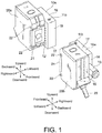
- FIG. 1 is a perspective view showing a state in which an air purge unit 10a of a first embodiment of the disclosure is mounted on a photoelectric sensor.
- the photoelectric sensor uses a light to detect the presence or absence of an object in a detection area or a surface state of the object.
- a transmission type When an object exists between the light projector 20a and the light receiver 20b, an amount of light received by the light receiver 20b is reduced so that the reduction is analyzed and the presence or absence of the object is detected.
- the photoelectric sensor in which the light projector and the light receiver are integral.
- the light from the photoelectric sensor is emitted toward a reflector or the detection object, the reflected light is received and analyzed by the same photoelectric sensor, thereby detecting the presence or absence of the object.
- the photoelectric sensor which acts as both the light projector and the light receiver is called a reflection type.
- the photoelectric sensor of the transmission type is described as an example, but the photoelectric sensor to which the present invention is applied is not limited to the transmission type, and may also be the reflection type.
- the optical sensor on which the air purge unit 10a is mounted is not limited to the photoelectric sensor.
- the air purge unit 10a can be mounted to various optical sensors by which the detection result is affected due to the dirt attached to the lens surface.
- the optical sensor may be a displacement sensor, an image sensor, or a bar-code reader.
- the configurations of the photoelectric sensor and the air purge unit 10a are described.
- two photoelectric sensors are prepared, one is used as the light projector 20a and the other is used as the light receiver 20b.
- the light projector 20a and the light receiver 20b are arranged so that the lens surfaces 21 of them are opposite to each other, and the light emitted by the light projector 20a is received by the light receiver 20b.
- directions of front and back, up and down, and left and right are defined by using an advancing direction of the emitted light as a frontward direction.
- directions of front and back, up and down, and left and right are defined by using an incident direction of the light as a frontward direction.
- the light projector 20a emits a light toward the detection area.
- the emitted light passes through the detection area, and is incident to the light receiver 20b.
- the light projector 20a includes a lens surface 21 and a second mounting part 22.
- the light projector 20a is connected to an amplifier and a power supply via a cable.
- at least any one of the amplifier and the power supply may be built in the light projector 20a.
- the lens surface 21 is a surface through which the light emitted from the light projector 20a passes.
- the lens surface 21 is made of any material that transmits a light, such as glass or resin.
- the second mounting part 22 is a portion on which the air purge unit 10a is mounted and which has a concave.
- the air purge unit 10a includes a first mounting part 14 having a convex. By fitting the convex of the first mounting part 14 and the concave of the second mounting part 22, the air purge unit 10a is mounted on the light projector 20a.
- the connection method of the first mounting part 14 and the second mounting part 22 may be any method, as long as the air purge unit 10a and the light projector 20a are detachable by the method.
- the second mounting part 22 is arranged on a left side surface and a right side surface of the light projector 20a. Therefore, the air purge unit 10a can be mounted on any one of the left side surface and the right side surface of the light projector 20a.
- the light receiver 20b receives the light emitted from the light projector 20a.
- the light receiver 20b analyzes the received light and detects the presence or absence of an object in the detection area.
- the light receiver 20b is connected to the power supply via a cable 23. Furthermore, the power supply may be built in the light receiver 20b. Besides, the light receiver 20b may send the detection result to other equipment via the cable 23.
- the light receiver 20b includes a lens surface 21 and a second mounting part 22.
- the lens surface 21 of the light receiver 20b is an incident surface of the light when the light receiver 20b receives the light.
- the lens surface 21 is made of any material that transmits a light, such as glass or resin.
- the second mounting part 22 of the light receiver 20b is a portion on which the air purge unit 10a is mounted, and has a configuration similar to the second mounting part 22 of the light projector 20a.
- the air purge units 10a for blowing out air to the lens surfaces 21 of the light projector 20a and the light receiver 20b are respectively mounted.
- the air purge unit 10a blows out air to the lens surface 21 of the light projector 20a or the light receiver 20b. Furthermore, the air purge unit 10a mounted on the light projector 20a and the air purge unit 10a mounted on the light receiver 20b have the similar configuration. The specific configuration of the air purge unit 10a is described below using FIG. 2 .
- an air purge unit 10a which has a configuration similar to the air purge unit 10a mounted on the left side surface of the light projector 20a is mounted on the right side surface of the light receiver 20b, it is necessary that the air purge unit 10a is mounted upside down. Therefore, in the air purge unit 10a of the light receiver 20b, a first surface 16 is located on a downward side, and a second surface 17 is located on an upward side.
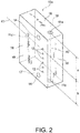
- FIG. 2 is a drawing showing the air purge unit 10a of the first embodiment of the present invention.
- FIG. 2 shows the air purge unit 10a which is mounted on the light projector 20a shown in FIG.1 .
- the air purge unit 10a includes a first connection part 11a, a second connection part 11b, a third connection part 11c, an air blowout part 12, a first mounting part 14, a first surface 16, a second surface 17, and a third surface 18.
- the first surface 16, the second surface 17 and the third surface 18 are side surfaces of the air purge unit 10a.
- a surface of the air purge unit 10a which is located farthest from the floor is set as the first surface 16, and a surface opposite to the first surface 16 is set as the second surface 17.
- a surface of the air purge unit 10a which is located in a direction intersecting with the first surface 16 and the second surface 17 is set as the third surface 18.
- the air purge unit 10a has a plurality of third surfaces 18.
- the first connection part 11a, the second connection part 11b, and the third connection part 11c are portions to which the air injector 13 for injecting air to the inside of the air purge unit 10a is connected.
- the first connection part 11a, the second connection part 11b, and the third connection part 11c are respectively arranged on the first surface 16, the second surface 17, and the third surface 18.
- the third connection part 11c may be arranged on at least any one of the plurality of third surfaces 18.
- the first connection part 11a, the second connection part 11b, and the third connection part 11c are generically named and simply referred to as a "connection part 11".
- the first connection part 11a and the second connection part 11b are located in a first straight line which perpendicularly intersects with the first surface 16 and the second surface 17. Besides, in the first straight line, a line segment which connects the connection part 11a and the second connection part 11b is set as a line segment 40.
- the third connection part 11c is located in a second straight line 41 which bisects the line segment 40. That is, a distance a from the first connection part 11a to the second straight line 41 is equal to a distance b from the second connection part 11b to the second straight line 41.
- the connection parts 11 of the air purge unit 10a are symmetrically arranged.
- the air purge unit 10a can be turned upside down and replaced from the light projector 20a to the light receiver 20b (see FIG. 1 ). At this time, the air blowout part 12 is located on the lens surface 21 side of the light receiver 20b.
- the second connection part 11b which is located on the lower side surface of the air purge unit 10a when the air purge unit 10a is mounted on the light projector 20a, is located on the upper side surface in a state that the air purge unit 10a is mounted on the light receiver 20b.
- the first connection part 11a which is located on the upper side surface of the air purge unit 10a when the air purge unit 10a is mounted on the light projector 20a, is located on the lower side surface in a state that the air purge unit 10a is mounted on the light receiver 20b. Furthermore, similar to the state when the air purge unit 10a is mounted on the light projector 20a, the third connection part 11c is located on the rear side surface of the air purge unit 10a. That is, no matter the air purge unit 10a is mounted on the light projector 20a or the light receiver 20b, the air injector 13 can be selectively mounted on any one of the upper side surface, the lower side surface, and the rear side surface of the air purge unit 10a.
- the air blowout part 12 blows out the air inside the air purge unit 10a to the lens surface 21 of the light projector 20a.
- the air injected from the air injector 13 which is connected to any one of the first connection part 11a, the second connection part 11b and the third connection part 11c is jetted from the air blowout part 12 through a flow path inside the air purge unit 10a.
- a blowout of air toward the lens surface 21 may be conducted at all times, or at regular time intervals.
- the air purge unit 10a of the embodiment is provided with a plurality of connection parts 11 for connecting the air injector 13. Therefore, the connection location of the air injector 13 can be selected corresponding to the installation position of the air purge unit 10a, and the degree of freedom in the installation position of the air purge unit 10a can be improved. That is, the air injector 13 is connected to any one of the connection parts 11 so that the installation of the air purge unit 10a is not obstructed by the air injector 13.
- the air purge unit 10a of the embodiment is detachably mounted on the optical sensor, so that the air purge unit 10a mounted on the optical sensor can be removed and can be replaced to other optical sensors.
- the air purge unit 10a can be mounted on the optical sensor; when the optical sensor is used in the environment in which the air purge unit 10a is unnecessary, the air purge unit 10a can be removed.
- the air injector 13 can be selectively mounted on any one of the upper side surface, the lower side surface, and the rear side surface of the air purge unit 10a.
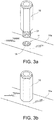
- FIGs. 3a and 3b are drawings relating to the connection part 11 of the air purge unit 10a of the first embodiment.
- FIG. 3a is a drawing showing a state before the air injector 13 is connected to the connection part 11;
- FIG. 3b is a drawing showing a state after the connection.
- the air injector 13 injects the air which is supplied from the air supply source to the inside of the air purge unit 10a.
- the air injector 13 has a screw part 31 at one end.
- the connection part 11 of the air purge unit 10a has a screw hole 15. The air injector 13 and the connection part 11 are connected by the screwing of the screw part 31 and the screw hole 15.
- connection of the air injector 13 and the connection part 11 may not be conducted by screwing, and any method can be taken in which the air injector 13 and the connection part 11 are detachable.
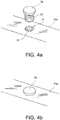
- FIGs. 4a and 4b are drawings relating to the connection part 11 of the air purge unit 10a of the first embodiment;
- FIG. 4a is a drawing showing a state before a plug 30 is connected to the connection part 11;
- FIG. 4b is a drawing showing a state after the connection.
- the plug 30 is loaded on the connection part 11 to which the air injector 13 is not connected, and the air is prevented from leaking out of the connection part 11 to which the air injector 13 is not connected.
- All of the first connection part 11a, the second connection part 11b and the third connection part 11c are associated with the air blowout part 12 via the flow path of air formed inside the air purge unit 10a, and the first connection part 11a, the second connection part 11b and the third connection part 11c are also associated with each other via the flow path. Therefore, when the air is injected from any one of the connection parts 11, the injected air leaks out of the other connection parts 11. Therefore, by attaching the plug 30 to the connection part 11 to which the air injector 13 is not connected, the air can be prevented from leaking out.
- the plug 30 has a screw part 31 at one end.
- the connection part 11 of the air purge unit 10a has a screw hole 15.
- the plug 30 and the connection part 11 are connected by the screwing of the screw part 31 and the screw hole 15.
- connection of the plug 30 and the connection part 11 may not be conducted by screwing, and any method can be taken in which the plug 30 and the connection part 11 are detachable.
- the air supply source and air purge unit 10a are connected by the air injector 13, and the air from the air supply source can be supplied to the inside of the air purge unit 10a via the air injector 13.
- the air purge unit 10a of the embodiment by attaching the plug 30 to the connection part 11 to which the air injector 13 is not connected, the air is prevented from leaking out of the connection part 11 to which the air injector 13 is not connected. Besides, because the plug 30 is detachably attached, the loading position of the plug 30 can be changed corresponding to the connection location of the air injector 13.
- the screw hole 15 of the connection part 11 of the air purge unit 10a and the screw part 31 of the air injector 13 are screwed
- the screw hole 15 of the connection part 11 of the air purge unit 10a and the screw part 31 of the plug 30 are screwed
- the air injector 13 and the plug 30 are more firmly connected to the air purge unit 10a.
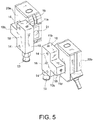
- FIG. 5 is a drawing showing an air purge unit 10b of the second embodiment of the present invention and a photoelectric sensor.
- the air purge unit 10a of the first embodiment and the air purge unit 10b of the second embodiment are different in the mounting location to the photoelectric sensor, the connection location of the air injector 13 and a body shape.
- Other configuration is similar to the configuration of the air purge unit 10a of the first embodiment.
- the air purge unit 10a of the first embodiment is mounted on the left side surface of the light projector 20a and the right side surface of the light receiver 20b (see FIG. 1 ), while in this embodiment, as shown in FIG. 5 , the air purge unit 10b is mounted on the right side surface of the light projector 20a and the left side surface of the light receiver 20b. As shown in FIG. 1 and FIG. 5 , the air purge units 10a, 10b can be mounted on both the right side surface and the left side surface of the photoelectric sensor (the light projector 20a and the light receiver 20b).
- the air injector 13 is connected to the third connection part 11c which is arranged on the rear side surface of the air purge unit 10a (see FIG. 1 ), while in the second embodiment, the air injector 13 is connected to the second connection part 11b which is arranged on the lower side surface of the air purge unit 10b mounted on the light projector 20a, and to the first connection part 11a which is arranged on the lower side surface of the air purge unit 10b mounted on the light receiver 20b.
- the air injector 13 can be selectively connected to any one of the first connection part 11a, the second connection part 11b, and the third connection part 11c.
- the body shape of the air purge unit 10a of the first embodiment is formed in a state that the third surface 18 is associated with the first surface 16 and the second surface 17, while the air purge unit 10b in the embodiment is formed so that upper and lower corners on the rearward side have a recessed shape, and the third surface 18 is not associated with the first surface 16 and the second surface 17.
- the third surface 18 may not be associated with the first surface 16 and the second surface 17, and may be arranged along the direction intersecting with the first surface 16 and the second surface 17.
- the body shape of the air purge unit 10b is set, as shown in FIG. 5 , to a shape that the upper and lower corners on the rearward side are recessed; in this way, the space saving of the air purge unit 10b can be realized.
- An air purge unit which is an air purge unit 10a that blows out air to a lens surface 21 of a optical sensor, including:
Landscapes
- Physics & Mathematics (AREA)
- General Physics & Mathematics (AREA)
- Optics & Photonics (AREA)
- Life Sciences & Earth Sciences (AREA)
- General Life Sciences & Earth Sciences (AREA)
- Geophysics (AREA)
- Geophysics And Detection Of Objects (AREA)
- Cleaning In General (AREA)
Abstract
Description
- The present invention relates to an air purge unit.
- Conventionally, in order to detect the presence or absence of an object in a detection area, a photoelectric sensor which is a kind of optical sensor is used. The photoelectric sensor is configured so that, for example, a light projector for emitting a light to the detection area and a light receiver for receiving the emitted light are included; when an object exists between the light projector and the light receiver, the light is shielded and an amount of light received by the light receiver is reduced. The photoelectric sensor detects the presence or absence of an object by analyzing this reduction. Furthermore, there is also a photoelectric sensor in which the light projector and the light receiver are accommodated in an integral housing, and the presence or absence of an object is detected by reflecting a light on the object and analyzing the reflection light.
- The photoelectric sensor may be installed in an environment of machining. In such an environment, there is an occasion that dirt such as dust or processing oil is attached to the lens surface of the photoelectric sensor through which the light passes, and the amount of light passing through the lens surface is reduced. Then, there is concern that the object cannot be appropriately detected. Therefore, a means is taken to mount an air purge unit for blowing out air to the lens surface on the photoelectric sensor, and to prevent an attachment of dirt to the lens surface. In patent literature 1, a means is disclosed to jet a gas from a gas supply hole around the lens surface, and prevent the attachment of dirt to the lens surface. Besides, generally, an air injector is connected to the air purge unit, and the air supplied from an air supply source is injected to the inside of the air purge unit via the air injector.
- [Patent literature 1] Japanese Laid-open No.
2012-002750 - Meanwhile, there is concern that a position in which an air injector is connected is usually fixed, and thus an installation position of the air purge unit or an installation position of the optical sensor is greatly limited.
- Therefore, the present invention provides an air purge unit having an improved degree of freedom in the installation position.
- The air purge unit of one aspect of the present invention is an air purge unit which blows out air to a lens surface of an optical sensor and includes: a first surface and a second surface which are opposite to each other; a third surface which is located along a direction intersecting with the first surface and the second surface; a first connection part, a second connection part and a third connection part which are respectively arranged on the first surface, the second surface and the third surface, and to which an air injector for injecting air to the inside of the air purge unit is selectively connected; and an air blowout part which blows out the air injected to the inside of the air purge unit to the lens surface of the optical sensor
- According to this aspect, in the air purge unit, a plurality of connection parts for connecting the air injector is arranged. Therefore, the connection location of the air injector can be selected corresponding to the position for installing the air purge unit, and the degree of freedom in the installation position of the air purge unit can be improved.
- In the above aspect, the air injector may be further included.
- According to this aspect, the air supply source and the air purge unit are connected by the air injector, and the air from the air supply source can be supplied to the inside of the air purge unit via the air injector.
- In the above aspect, a plug may be further included which is detachably attached to a connection part which is among the first connection part, the second connection part and the third connection part and to which the air injector is not connected.
- According to this aspect, by attaching the plug to the connection part to which the air injector is not connected, the air is prevented from leaking out of the connection part to which the air injector is not connected. Besides, the plug is detachably attached so that the attachment position of the plug can be changed corresponding to the connection location of the air injector.
- In the above aspect, each of the first connection part, the second connection part and the third connection part may include a screw hole, the air injector may include a screw part screwed with the screw hole, and the plug may include a screw part screwed with the screw hole.
- According to this aspect, the screw hole of the connection part of the air purge unit and the screw part of the air injector are screwed, the screw hole of the connection part of the air purge unit and the screw part of the plug are screwed, and the air injector and the plug can be more firmly connected to the air purge unit.
- In the above aspect, the air purge unit may be detachably installed on the optical sensor.
- According to this aspect, the air purge unit mounted on the optical sensor can be removed and can be replaced to other optical sensors. Besides, when the optical sensor is used in the environment in which dirt is attached to the lens surface of the optical sensor and the air purge unit is necessary, the air purge unit can be mounted on the optical sensor; when the optical sensor is used in the environment in which the air purge unit is unnecessary, the air purge unit can be removed.
- In the above aspect, the first connection part and the second connection part may be located in a first straight line which perpendicularly intersects with the first surface and the second surface, and the third connection part may be located in a second straight line which bisects a line segment in the first straight line connecting the first connection part and the second connection part.
- According to this aspect, even when the air purge unit is mounted on any one of the optical sensors which are installed opposite to each other, the air injector can be selectively mounted on any one of an upper side surface, a lower side surface and a rear side surface of the air purge unit.
- According to the present invention, an air purge unit having an improved degree of freedom in the installation position can be provided.
-
-
FIG. 1 is a perspective view showing a state in which an air purge unit of a first embodiment of the present invention is mounted on a photoelectric sensor. -
FIG. 2 is a drawing showing the air purge unit of the first embodiment of the present invention. -
FIGs. 3a and 3b relate to a connection part of the air purge unit of the first embodiment of the present invention;FIG. 3a is a drawing showing a state before an air injector is connected to the connection part, andFIG. 3b is a drawing showing a state after the connection. -
FIGs. 4a and 4b relate to a connection part of the air purge unit of the first embodiment of the present invention;FIG. 4a is a drawing showing a state before a plug is connected to the connection part, andFIG. 4b is a drawing showing a state after the connection. -
FIG. 5 is a perspective view showing a state in which an air purge unit of a second embodiment of the present invention is connected to the photoelectric sensor. - Embodiments of the present invention are described with reference to the attached drawings. Furthermore, in each drawing, the parts which are denoted by the same symbol have the same or similar configuration.
-
FIG. 1 is a perspective view showing a state in which anair purge unit 10a of a first embodiment of the disclosure is mounted on a photoelectric sensor. The photoelectric sensor uses a light to detect the presence or absence of an object in a detection area or a surface state of the object. There is a plurality of detection methods using the photoelectric sensor. For example, two photoelectric sensors are prepared, one photoelectric sensor is used as alight projector 20a for emitting the light, and the other photoelectric sensor is used as alight receiver 20b for receiving the light. When an object exists between thelight projector 20a and thelight receiver 20b, an amount of light received by thelight receiver 20b is reduced so that the reduction is analyzed and the presence or absence of the object is detected. The photoelectric sensor used in the above detection method is called a transmission type. - Besides, as another detection method, there is a method for conducting the detection by using a photoelectric sensor in which the light projector and the light receiver are integral. The light from the photoelectric sensor is emitted toward a reflector or the detection object, the reflected light is received and analyzed by the same photoelectric sensor, thereby detecting the presence or absence of the object. The photoelectric sensor which acts as both the light projector and the light receiver is called a reflection type. In the embodiment, the photoelectric sensor of the transmission type is described as an example, but the photoelectric sensor to which the present invention is applied is not limited to the transmission type, and may also be the reflection type.
- Furthermore, in the specification, a state in which the
air purge unit 10a is mounted on the photoelectric sensor is described as an example, but the optical sensor on which theair purge unit 10a is mounted is not limited to the photoelectric sensor. Theair purge unit 10a can be mounted to various optical sensors by which the detection result is affected due to the dirt attached to the lens surface. For example, the optical sensor may be a displacement sensor, an image sensor, or a bar-code reader. - With reference to
FIG. 1 , the configurations of the photoelectric sensor and theair purge unit 10a are described. In the embodiment, two photoelectric sensors are prepared, one is used as thelight projector 20a and the other is used as thelight receiver 20b. Thelight projector 20a and thelight receiver 20b are arranged so that the lens surfaces 21 of them are opposite to each other, and the light emitted by thelight projector 20a is received by thelight receiver 20b. - For convenience of description, in regard to the
light projector 20a, when thelight projector 20a is arranged on the floor, directions of front and back, up and down, and left and right are defined by using an advancing direction of the emitted light as a frontward direction. Besides, in regard to thelight receiver 20b, when thelight receiver 20b is arranged on the floor, directions of front and back, up and down, and left and right are defined by using an incident direction of the light as a frontward direction. - The
light projector 20a emits a light toward the detection area. The emitted light passes through the detection area, and is incident to thelight receiver 20b. Thelight projector 20a includes alens surface 21 and a second mountingpart 22. Besides, although it is not shown in the drawing, thelight projector 20a is connected to an amplifier and a power supply via a cable. Furthermore, at least any one of the amplifier and the power supply may be built in thelight projector 20a. - The
lens surface 21 is a surface through which the light emitted from thelight projector 20a passes. Thelens surface 21 is made of any material that transmits a light, such as glass or resin. - The second mounting
part 22 is a portion on which theair purge unit 10a is mounted and which has a concave. Besides, theair purge unit 10a includes a first mountingpart 14 having a convex. By fitting the convex of the first mountingpart 14 and the concave of the second mountingpart 22, theair purge unit 10a is mounted on thelight projector 20a. Furthermore, the connection method of the first mountingpart 14 and the second mountingpart 22 may be any method, as long as theair purge unit 10a and thelight projector 20a are detachable by the method. The second mountingpart 22 is arranged on a left side surface and a right side surface of thelight projector 20a. Therefore, theair purge unit 10a can be mounted on any one of the left side surface and the right side surface of thelight projector 20a. - The
light receiver 20b receives the light emitted from thelight projector 20a. Thelight receiver 20b analyzes the received light and detects the presence or absence of an object in the detection area. Thelight receiver 20b is connected to the power supply via acable 23. Furthermore, the power supply may be built in thelight receiver 20b. Besides, thelight receiver 20b may send the detection result to other equipment via thecable 23. - The
light receiver 20b includes alens surface 21 and a second mountingpart 22. Thelens surface 21 of thelight receiver 20b is an incident surface of the light when thelight receiver 20b receives the light. Thelens surface 21 is made of any material that transmits a light, such as glass or resin. - The second mounting
part 22 of thelight receiver 20b is a portion on which theair purge unit 10a is mounted, and has a configuration similar to the second mountingpart 22 of thelight projector 20a. - On the left side surface of the
light projector 20a and the right side surface of thelight receiver 20b, theair purge units 10a for blowing out air to the lens surfaces 21 of thelight projector 20a and thelight receiver 20b are respectively mounted. - The
air purge unit 10a blows out air to thelens surface 21 of thelight projector 20a or thelight receiver 20b. Furthermore, theair purge unit 10a mounted on thelight projector 20a and theair purge unit 10a mounted on thelight receiver 20b have the similar configuration. The specific configuration of theair purge unit 10a is described below usingFIG. 2 . - Furthermore, in order that an
air purge unit 10a which has a configuration similar to theair purge unit 10a mounted on the left side surface of thelight projector 20a is mounted on the right side surface of thelight receiver 20b, it is necessary that theair purge unit 10a is mounted upside down. Therefore, in theair purge unit 10a of thelight receiver 20b, afirst surface 16 is located on a downward side, and asecond surface 17 is located on an upward side. -
FIG. 2 is a drawing showing theair purge unit 10a of the first embodiment of the present invention.FIG. 2 shows theair purge unit 10a which is mounted on thelight projector 20a shown inFIG.1 . Theair purge unit 10a includes afirst connection part 11a, asecond connection part 11b, athird connection part 11c, anair blowout part 12, a first mountingpart 14, afirst surface 16, asecond surface 17, and athird surface 18. - The
first surface 16, thesecond surface 17 and thethird surface 18 are side surfaces of theair purge unit 10a. When thelight projector 20a is arranged on the floor, a surface of theair purge unit 10a which is located farthest from the floor is set as thefirst surface 16, and a surface opposite to thefirst surface 16 is set as thesecond surface 17. Besides, a surface of theair purge unit 10a which is located in a direction intersecting with thefirst surface 16 and thesecond surface 17 is set as thethird surface 18. Theair purge unit 10a has a plurality of third surfaces 18. - The
first connection part 11a, thesecond connection part 11b, and thethird connection part 11c are portions to which theair injector 13 for injecting air to the inside of theair purge unit 10a is connected. Thefirst connection part 11a, thesecond connection part 11b, and thethird connection part 11c are respectively arranged on thefirst surface 16, thesecond surface 17, and thethird surface 18. Here, thethird connection part 11c may be arranged on at least any one of the plurality of third surfaces 18. Furthermore, in the specification, thefirst connection part 11a, thesecond connection part 11b, and thethird connection part 11c are generically named and simply referred to as a "connection part 11". - The
first connection part 11a and thesecond connection part 11b are located in a first straight line which perpendicularly intersects with thefirst surface 16 and thesecond surface 17. Besides, in the first straight line, a line segment which connects theconnection part 11a and thesecond connection part 11b is set as aline segment 40. Thethird connection part 11c is located in a secondstraight line 41 which bisects theline segment 40. That is, a distance a from thefirst connection part 11a to the secondstraight line 41 is equal to a distance b from thesecond connection part 11b to the secondstraight line 41. Using the secondstraight line 41 in which thethird connection part 11c is located as a symmetric axis, theconnection parts 11 of theair purge unit 10a are symmetrically arranged. - Because such a configuration is used, the
air purge unit 10a can be turned upside down and replaced from thelight projector 20a to thelight receiver 20b (seeFIG. 1 ). At this time, theair blowout part 12 is located on thelens surface 21 side of thelight receiver 20b. Thesecond connection part 11b, which is located on the lower side surface of theair purge unit 10a when theair purge unit 10a is mounted on thelight projector 20a, is located on the upper side surface in a state that theair purge unit 10a is mounted on thelight receiver 20b. Besides, thefirst connection part 11a, which is located on the upper side surface of theair purge unit 10a when theair purge unit 10a is mounted on thelight projector 20a, is located on the lower side surface in a state that theair purge unit 10a is mounted on thelight receiver 20b. Furthermore, similar to the state when theair purge unit 10a is mounted on thelight projector 20a, thethird connection part 11c is located on the rear side surface of theair purge unit 10a. That is, no matter theair purge unit 10a is mounted on thelight projector 20a or thelight receiver 20b, theair injector 13 can be selectively mounted on any one of the upper side surface, the lower side surface, and the rear side surface of theair purge unit 10a. - The
air blowout part 12 blows out the air inside theair purge unit 10a to thelens surface 21 of thelight projector 20a. The air injected from theair injector 13 which is connected to any one of thefirst connection part 11a, thesecond connection part 11b and thethird connection part 11c is jetted from theair blowout part 12 through a flow path inside theair purge unit 10a. Furthermore, a blowout of air toward thelens surface 21 may be conducted at all times, or at regular time intervals. - The
air purge unit 10a of the embodiment is provided with a plurality ofconnection parts 11 for connecting theair injector 13. Therefore, the connection location of theair injector 13 can be selected corresponding to the installation position of theair purge unit 10a, and the degree of freedom in the installation position of theair purge unit 10a can be improved. That is, theair injector 13 is connected to any one of theconnection parts 11 so that the installation of theair purge unit 10a is not obstructed by theair injector 13. - Besides, the
air purge unit 10a of the embodiment is detachably mounted on the optical sensor, so that theair purge unit 10a mounted on the optical sensor can be removed and can be replaced to other optical sensors. Besides, when the optical sensor is used in the environment in which dirt is attached to thelens surface 21 of the optical sensor and theair purge unit 10a is necessary, theair purge unit 10a can be mounted on the optical sensor; when the optical sensor is used in the environment in which theair purge unit 10a is unnecessary, theair purge unit 10a can be removed. - Furthermore, according to the
air purge unit 10a of the embodiment, even when theair purge unit 10a is mounted on any one of the optical sensors which are installed opposite to each other, theair injector 13 can be selectively mounted on any one of the upper side surface, the lower side surface, and the rear side surface of theair purge unit 10a. -
FIGs. 3a and 3b are drawings relating to theconnection part 11 of theair purge unit 10a of the first embodiment.FIG. 3a is a drawing showing a state before theair injector 13 is connected to theconnection part 11;FIG. 3b is a drawing showing a state after the connection. - The
air injector 13 injects the air which is supplied from the air supply source to the inside of theair purge unit 10a. Theair injector 13 has ascrew part 31 at one end. Besides, theconnection part 11 of theair purge unit 10a has ascrew hole 15. Theair injector 13 and theconnection part 11 are connected by the screwing of thescrew part 31 and thescrew hole 15. - Furthermore, the connection of the
air injector 13 and theconnection part 11 may not be conducted by screwing, and any method can be taken in which theair injector 13 and theconnection part 11 are detachable. -
FIGs. 4a and 4b are drawings relating to theconnection part 11 of theair purge unit 10a of the first embodiment;FIG. 4a is a drawing showing a state before aplug 30 is connected to theconnection part 11;FIG. 4b is a drawing showing a state after the connection. - The
plug 30 is loaded on theconnection part 11 to which theair injector 13 is not connected, and the air is prevented from leaking out of theconnection part 11 to which theair injector 13 is not connected. All of thefirst connection part 11a, thesecond connection part 11b and thethird connection part 11c are associated with theair blowout part 12 via the flow path of air formed inside theair purge unit 10a, and thefirst connection part 11a, thesecond connection part 11b and thethird connection part 11c are also associated with each other via the flow path. Therefore, when the air is injected from any one of theconnection parts 11, the injected air leaks out of theother connection parts 11. Therefore, by attaching theplug 30 to theconnection part 11 to which theair injector 13 is not connected, the air can be prevented from leaking out. - The
plug 30 has ascrew part 31 at one end. Besides, theconnection part 11 of theair purge unit 10a has ascrew hole 15. Theplug 30 and theconnection part 11 are connected by the screwing of thescrew part 31 and thescrew hole 15. - Furthermore, the connection of the
plug 30 and theconnection part 11 may not be conducted by screwing, and any method can be taken in which theplug 30 and theconnection part 11 are detachable. - According to the
air purge unit 10a of the embodiment, the air supply source andair purge unit 10a are connected by theair injector 13, and the air from the air supply source can be supplied to the inside of theair purge unit 10a via theair injector 13. - Besides, according to the
air purge unit 10a of the embodiment, by attaching theplug 30 to theconnection part 11 to which theair injector 13 is not connected, the air is prevented from leaking out of theconnection part 11 to which theair injector 13 is not connected. Besides, because theplug 30 is detachably attached, the loading position of theplug 30 can be changed corresponding to the connection location of theair injector 13. - Furthermore, according to the
air purge unit 10a of the embodiment, thescrew hole 15 of theconnection part 11 of theair purge unit 10a and thescrew part 31 of theair injector 13 are screwed, thescrew hole 15 of theconnection part 11 of theair purge unit 10a and thescrew part 31 of theplug 30 are screwed, and theair injector 13 and theplug 30 are more firmly connected to theair purge unit 10a. -
FIG. 5 is a drawing showing anair purge unit 10b of the second embodiment of the present invention and a photoelectric sensor. Theair purge unit 10a of the first embodiment and theair purge unit 10b of the second embodiment are different in the mounting location to the photoelectric sensor, the connection location of theair injector 13 and a body shape. Other configuration is similar to the configuration of theair purge unit 10a of the first embodiment. - The
air purge unit 10a of the first embodiment is mounted on the left side surface of thelight projector 20a and the right side surface of thelight receiver 20b (seeFIG. 1 ), while in this embodiment, as shown inFIG. 5 , theair purge unit 10b is mounted on the right side surface of thelight projector 20a and the left side surface of thelight receiver 20b. As shown inFIG. 1 andFIG. 5 , theair purge units light projector 20a and thelight receiver 20b). - Besides, in the
air purge unit 10a of the first embodiment, theair injector 13 is connected to thethird connection part 11c which is arranged on the rear side surface of theair purge unit 10a (seeFIG. 1 ), while in the second embodiment, theair injector 13 is connected to thesecond connection part 11b which is arranged on the lower side surface of theair purge unit 10b mounted on thelight projector 20a, and to thefirst connection part 11a which is arranged on the lower side surface of theair purge unit 10b mounted on thelight receiver 20b. As shown inFIG. 1 andFIG. 5 , theair injector 13 can be selectively connected to any one of thefirst connection part 11a, thesecond connection part 11b, and thethird connection part 11c. - The body shape of the
air purge unit 10a of the first embodiment is formed in a state that thethird surface 18 is associated with thefirst surface 16 and thesecond surface 17, while theair purge unit 10b in the embodiment is formed so that upper and lower corners on the rearward side have a recessed shape, and thethird surface 18 is not associated with thefirst surface 16 and thesecond surface 17. Thethird surface 18 may not be associated with thefirst surface 16 and thesecond surface 17, and may be arranged along the direction intersecting with thefirst surface 16 and thesecond surface 17. Besides, the body shape of theair purge unit 10b is set, as shown inFIG. 5 , to a shape that the upper and lower corners on the rearward side are recessed; in this way, the space saving of theair purge unit 10b can be realized. - The embodiments described above intend to make it easy to understand the present invention, instead of interpreting the present invention in a limitative way. Each element included in the embodiments, and arrangements, materials, conditions, shapes and sizes thereof can be appropriately changed instead of being limited to the illustrations. Besides, the configurations shown in different embodiments may be partially substituted or combined with each other.
- An air purge unit, which is an
air purge unit 10a that blows out air to alens surface 21 of a optical sensor, including: - a
first surface 16 and asecond surface 17 which are opposite to each other; - a
third surface 18 which is located along a direction intersecting with thefirst surface 16 and thesecond surface 17; - a
first connection part 11a, asecond connection part 11b and athird connection part 11c which are respectively arranged on thefirst surface 16, thesecond surface 17 and thethird surface 18, and to which anair injector 13 for injecting air to the inside of theair purge unit 10a is selectively connected; and - an
air blowout part 12 which blows out the air injected to the inside of theair purge unit 10a to thelens surface 21 of the optical sensor. -
- 10a
- Air purge unit
- 10b
- Air purge unit
- 11
- Connection part
- 11a
- First connection part
- 11b
- Second connection part
- 11c
- Third connection part
- 12
- Air blowout part
- 13
- Air injector
- 14
- First mounting part
- 15
- Screw hole
- 16
- First surface
- 17
- Second surface
- 18
- Third surface
- 20a
- Light projector
- 20b
- Light receiver
- 21
- Lens surface
- 22
- Second mounting part
- 23
- Cable
- 30
- Plug
- 31
- Screw part
- 40
- Line segment
- 41
- Second straight line
Claims (6)
- An air purge unit (10a, 10b) which blows out air to a lens surface (21) of an optical sensor (20a, 20b), characterized in that, comprising:a first surface (16) and a second surface (17) which are opposite to each other;a third surface (18) which is located along a direction intersecting with the first surface (16) and the second surface (17);a first connection part (11a), a second connection part (11b) and a third connection part (11c) which are respectively arranged on the first surface (16), the second surface (17) and the third surface (18), and to which an air injector (13) for injecting air to the inside of the air purge unit (10a, 10b) is selectively connected; andan air blowout part (12) which blows out the air injected to the inside of the air purge unit (10a, 10b) to the lens surface (21) of the optical sensor (20a, 20b).
- The air purge unit (10a, 10b) according to claim 1, characterized in that, further comprising the air injector (13).
- The air purge unit (10a, 10b) according to claim 1 or 2, characterized in that, further comprising a plug (30) detachably attached to a connection part which is among the first connection part (11a), the second connection part (11b) and the third connection part (11c) and to which the air injector (13) is not connected.
- The air purge unit (10a, 10b) according to claim 3, characterized in that, wherein each of the first connection part (11a), the second connection part (11b) and the third connection part (11c) comprises a screw hole (15),
the air injector (13) comprises a screw part (31) screwed with the screw hole (15), and
the plug (30) comprises a screw part (31) screwed with the screw hole (15). - The air purge unit (10a, 10b) according to any one of claims 1 to 4, characterized in that, which is detachably mounted on the optical sensor (20a, 20b).
- The air purge unit (10a, 10b) according to any one of claims 1 to 5, characterized in that, wherein the first connection part (11a) and the second connection part (11b) are located in a first straight line which perpendicularly intersects with the first surface (16) and the second surface (17), and the third connection part (11c) is located in a second straight line (41) which bisects a line segment (40) in the first straight line connecting the first connection part (11a) and the second connection part (11b).
Applications Claiming Priority (1)
| Application Number | Priority Date | Filing Date | Title |
|---|---|---|---|
| JP2017193323A JP6955671B2 (en) | 2017-10-03 | 2017-10-03 | Air purge unit |
Publications (2)
| Publication Number | Publication Date |
|---|---|
| EP3466555A1 true EP3466555A1 (en) | 2019-04-10 |
| EP3466555B1 EP3466555B1 (en) | 2021-04-07 |
Family
ID=63557254
Family Applications (1)
| Application Number | Title | Priority Date | Filing Date |
|---|---|---|---|
| EP18193583.4A Active EP3466555B1 (en) | 2017-10-03 | 2018-09-11 | Air purge unit |
Country Status (4)
| Country | Link |
|---|---|
| US (1) | US10739582B2 (en) |
| EP (1) | EP3466555B1 (en) |
| JP (1) | JP6955671B2 (en) |
| CN (1) | CN109590282B (en) |
Families Citing this family (2)
| Publication number | Priority date | Publication date | Assignee | Title |
|---|---|---|---|---|
| CN113083797B (en) * | 2021-03-30 | 2023-01-24 | 中国科学院计算技术研究所 | Automatic detection of dust removal device and dust removal chassis |
| US12372620B2 (en) * | 2021-12-15 | 2025-07-29 | Ford Global Technologies, Llc | Sensor assembly with deflector |
Citations (5)
| Publication number | Priority date | Publication date | Assignee | Title |
|---|---|---|---|---|
| DE19707223A1 (en) * | 1996-02-27 | 1997-09-04 | Fuji Photo Optical Co Ltd | Protection system for camera lens system against rain water |
| KR100625103B1 (en) * | 2003-10-14 | 2006-09-19 | 주식회사 메디아나전자 | Semiconductor chip contamination prevention device using air curtain method |
| DE102007016099A1 (en) * | 2007-03-27 | 2008-10-02 | Siemens Ag | Method for cleaning electromagnetic radiation sensor, especially radar or track vehicle sensor useful in radar and train technology lessens effects of environmental conditions, especially weather on sensor functioning |
| JP2012002750A (en) | 2010-06-18 | 2012-01-05 | Tdk Corp | Optical detector |
| CN107219900A (en) * | 2017-06-02 | 2017-09-29 | 丁继来 | A kind of automatically cleaning computer of high efficiency and heat radiation |
Family Cites Families (9)
| Publication number | Priority date | Publication date | Assignee | Title |
|---|---|---|---|---|
| JPS59109311U (en) * | 1983-01-11 | 1984-07-23 | オムロン株式会社 | Photoelectric switch lens dirt prevention device |
| JPH0736027U (en) * | 1993-12-10 | 1995-07-04 | 株式会社キーエンス | Photoelectric detector purifier |
| JPH1196865A (en) * | 1997-09-18 | 1999-04-09 | Fuji Electric Co Ltd | Air purge method of photoelectric switch and photoelectric switch |
| US7468161B2 (en) * | 2002-04-15 | 2008-12-23 | Ventana Medical Systems, Inc. | Automated high volume slide processing system |
| KR20110026220A (en) * | 2009-09-07 | 2011-03-15 | 삼성전기주식회사 | Foreign body removal system of car camera |
| CN202479165U (en) * | 2012-03-20 | 2012-10-10 | 重庆德凯覆铜板有限公司 | Air pressure type device for cleaning laminated steel |
| CN204148193U (en) * | 2014-09-11 | 2015-02-11 | 常熟实盈光学科技有限公司 | Lens cleaning device |
| FR3027007B1 (en) * | 2014-10-10 | 2017-12-08 | Valeo Systemes Dessuyage | DEVICE FOR CLEANING A DRIVING CAMERA FOR DRIVING A MOTOR VEHICLE |
| EP3631409B1 (en) * | 2017-05-24 | 2025-06-25 | Ventana Medical Systems, Inc. | Gas knife using parallelogram flow |
-
2017
- 2017-10-03 JP JP2017193323A patent/JP6955671B2/en active Active
-
2018
- 2018-09-11 EP EP18193583.4A patent/EP3466555B1/en active Active
- 2018-09-11 CN CN201811054341.1A patent/CN109590282B/en active Active
- 2018-09-17 US US16/133,662 patent/US10739582B2/en active Active
Patent Citations (5)
| Publication number | Priority date | Publication date | Assignee | Title |
|---|---|---|---|---|
| DE19707223A1 (en) * | 1996-02-27 | 1997-09-04 | Fuji Photo Optical Co Ltd | Protection system for camera lens system against rain water |
| KR100625103B1 (en) * | 2003-10-14 | 2006-09-19 | 주식회사 메디아나전자 | Semiconductor chip contamination prevention device using air curtain method |
| DE102007016099A1 (en) * | 2007-03-27 | 2008-10-02 | Siemens Ag | Method for cleaning electromagnetic radiation sensor, especially radar or track vehicle sensor useful in radar and train technology lessens effects of environmental conditions, especially weather on sensor functioning |
| JP2012002750A (en) | 2010-06-18 | 2012-01-05 | Tdk Corp | Optical detector |
| CN107219900A (en) * | 2017-06-02 | 2017-09-29 | 丁继来 | A kind of automatically cleaning computer of high efficiency and heat radiation |
Also Published As
| Publication number | Publication date |
|---|---|
| EP3466555B1 (en) | 2021-04-07 |
| US20190101749A1 (en) | 2019-04-04 |
| JP6955671B2 (en) | 2021-10-27 |
| CN109590282A (en) | 2019-04-09 |
| JP2019063750A (en) | 2019-04-25 |
| CN109590282B (en) | 2021-05-18 |
| US10739582B2 (en) | 2020-08-11 |
Similar Documents
| Publication | Publication Date | Title |
|---|---|---|
| US9360183B2 (en) | Mirror apparatus for a vehicle | |
| US11614396B2 (en) | Fire detection device | |
| EP3466555B1 (en) | Air purge unit | |
| CA2940309C (en) | Sensor with a radiant indicator | |
| EP3932571B1 (en) | Air purge unit | |
| EP3382076A1 (en) | Weft yarn sensing device of an air jet loom | |
| EP4040214B1 (en) | Inspection assembly | |
| WO2018174343A1 (en) | Backlight unit | |
| US20080099309A1 (en) | Roller for a roller conveyor | |
| EP2463807A1 (en) | Card reader | |
| US8690058B2 (en) | Card reader | |
| CN101770040A (en) | Multi-optical axis photoelectric sensor | |
| US10124734B1 (en) | Vehicle mirror assembly | |
| ES2926666T3 (en) | Optical liquid level detection sensor and liquid overfill prevention system comprising such a sensor | |
| CN107690591A (en) | For the holding equipment for the driver element for keeping deflecting mirror arrangement, there are the detection device that deflecting mirror is arranged, and motor vehicles | |
| KR20060120440A (en) | Optical devices, cleaning methods, computer optical mice and cleaning systems | |
| US10760952B2 (en) | Photoelectric sensor comprising at least one of a light projecting side light guide part and a light receiving side light guide part extends with at least a part thereof inclined with respect to a predetermined direction | |
| EP3172093A1 (en) | Rain detection device | |
| JP6889410B2 (en) | Photoelectric sensor | |
| US8767064B2 (en) | Combination of optical connector inspection apparatus and optical connector capable of inspecting a held posture of an optical fiber | |
| KR20150083768A (en) | Light projection head and optical sensor | |
| KR100944191B1 (en) | Plate-shaped member detection device | |
| CN220491162U (en) | Terminal equipment detects light source | |
| KR101519763B1 (en) | Blind spot detection indicator for vehicle | |
| FI112289B (en) | A procedure for regulating lighting and an electronic device |
Legal Events
| Date | Code | Title | Description |
|---|---|---|---|
| PUAI | Public reference made under article 153(3) epc to a published international application that has entered the european phase |
Free format text: ORIGINAL CODE: 0009012 |
|
| STAA | Information on the status of an ep patent application or granted ep patent |
Free format text: STATUS: REQUEST FOR EXAMINATION WAS MADE |
|
| 17P | Request for examination filed |
Effective date: 20181221 |
|
| AK | Designated contracting states |
Kind code of ref document: A1 Designated state(s): AL AT BE BG CH CY CZ DE DK EE ES FI FR GB GR HR HU IE IS IT LI LT LU LV MC MK MT NL NO PL PT RO RS SE SI SK SM TR |
|
| AX | Request for extension of the european patent |
Extension state: BA ME |
|
| RBV | Designated contracting states (corrected) |
Designated state(s): AL AT BE BG CH CY CZ DE DK EE ES FI FR GB GR HR HU IE IS IT LI LT LU LV MC MK MT NL NO PL PT RO RS SE SI SK SM TR |
|
| STAA | Information on the status of an ep patent application or granted ep patent |
Free format text: STATUS: EXAMINATION IS IN PROGRESS |
|
| 17Q | First examination report despatched |
Effective date: 20191127 |
|
| GRAP | Despatch of communication of intention to grant a patent |
Free format text: ORIGINAL CODE: EPIDOSNIGR1 |
|
| STAA | Information on the status of an ep patent application or granted ep patent |
Free format text: STATUS: GRANT OF PATENT IS INTENDED |
|
| INTG | Intention to grant announced |
Effective date: 20201215 |
|
| GRAS | Grant fee paid |
Free format text: ORIGINAL CODE: EPIDOSNIGR3 |
|
| GRAA | (expected) grant |
Free format text: ORIGINAL CODE: 0009210 |
|
| STAA | Information on the status of an ep patent application or granted ep patent |
Free format text: STATUS: THE PATENT HAS BEEN GRANTED |
|
| AK | Designated contracting states |
Kind code of ref document: B1 Designated state(s): AL AT BE BG CH CY CZ DE DK EE ES FI FR GB GR HR HU IE IS IT LI LT LU LV MC MK MT NL NO PL PT RO RS SE SI SK SM TR |
|
| REG | Reference to a national code |
Ref country code: GB Ref legal event code: FG4D |
|
| REG | Reference to a national code |
Ref country code: AT Ref legal event code: REF Ref document number: 1379002 Country of ref document: AT Kind code of ref document: T Effective date: 20210415 Ref country code: CH Ref legal event code: EP |
|
| REG | Reference to a national code |
Ref country code: DE Ref legal event code: R096 Ref document number: 602018015056 Country of ref document: DE |
|
| REG | Reference to a national code |
Ref country code: IE Ref legal event code: FG4D |
|
| REG | Reference to a national code |
Ref country code: LT Ref legal event code: MG9D |
|
| REG | Reference to a national code |
Ref country code: NL Ref legal event code: MP Effective date: 20210407 Ref country code: AT Ref legal event code: MK05 Ref document number: 1379002 Country of ref document: AT Kind code of ref document: T Effective date: 20210407 |
|
| PG25 | Lapsed in a contracting state [announced via postgrant information from national office to epo] |
Ref country code: FI Free format text: LAPSE BECAUSE OF FAILURE TO SUBMIT A TRANSLATION OF THE DESCRIPTION OR TO PAY THE FEE WITHIN THE PRESCRIBED TIME-LIMIT Effective date: 20210407 Ref country code: HR Free format text: LAPSE BECAUSE OF FAILURE TO SUBMIT A TRANSLATION OF THE DESCRIPTION OR TO PAY THE FEE WITHIN THE PRESCRIBED TIME-LIMIT Effective date: 20210407 Ref country code: LT Free format text: LAPSE BECAUSE OF FAILURE TO SUBMIT A TRANSLATION OF THE DESCRIPTION OR TO PAY THE FEE WITHIN THE PRESCRIBED TIME-LIMIT Effective date: 20210407 Ref country code: NL Free format text: LAPSE BECAUSE OF FAILURE TO SUBMIT A TRANSLATION OF THE DESCRIPTION OR TO PAY THE FEE WITHIN THE PRESCRIBED TIME-LIMIT Effective date: 20210407 Ref country code: BG Free format text: LAPSE BECAUSE OF FAILURE TO SUBMIT A TRANSLATION OF THE DESCRIPTION OR TO PAY THE FEE WITHIN THE PRESCRIBED TIME-LIMIT Effective date: 20210707 Ref country code: AT Free format text: LAPSE BECAUSE OF FAILURE TO SUBMIT A TRANSLATION OF THE DESCRIPTION OR TO PAY THE FEE WITHIN THE PRESCRIBED TIME-LIMIT Effective date: 20210407 |
|
| PG25 | Lapsed in a contracting state [announced via postgrant information from national office to epo] |
Ref country code: PL Free format text: LAPSE BECAUSE OF FAILURE TO SUBMIT A TRANSLATION OF THE DESCRIPTION OR TO PAY THE FEE WITHIN THE PRESCRIBED TIME-LIMIT Effective date: 20210407 Ref country code: NO Free format text: LAPSE BECAUSE OF FAILURE TO SUBMIT A TRANSLATION OF THE DESCRIPTION OR TO PAY THE FEE WITHIN THE PRESCRIBED TIME-LIMIT Effective date: 20210707 Ref country code: PT Free format text: LAPSE BECAUSE OF FAILURE TO SUBMIT A TRANSLATION OF THE DESCRIPTION OR TO PAY THE FEE WITHIN THE PRESCRIBED TIME-LIMIT Effective date: 20210809 Ref country code: LV Free format text: LAPSE BECAUSE OF FAILURE TO SUBMIT A TRANSLATION OF THE DESCRIPTION OR TO PAY THE FEE WITHIN THE PRESCRIBED TIME-LIMIT Effective date: 20210407 Ref country code: SE Free format text: LAPSE BECAUSE OF FAILURE TO SUBMIT A TRANSLATION OF THE DESCRIPTION OR TO PAY THE FEE WITHIN THE PRESCRIBED TIME-LIMIT Effective date: 20210407 Ref country code: RS Free format text: LAPSE BECAUSE OF FAILURE TO SUBMIT A TRANSLATION OF THE DESCRIPTION OR TO PAY THE FEE WITHIN THE PRESCRIBED TIME-LIMIT Effective date: 20210407 Ref country code: IS Free format text: LAPSE BECAUSE OF FAILURE TO SUBMIT A TRANSLATION OF THE DESCRIPTION OR TO PAY THE FEE WITHIN THE PRESCRIBED TIME-LIMIT Effective date: 20210807 Ref country code: GR Free format text: LAPSE BECAUSE OF FAILURE TO SUBMIT A TRANSLATION OF THE DESCRIPTION OR TO PAY THE FEE WITHIN THE PRESCRIBED TIME-LIMIT Effective date: 20210708 |
|
| REG | Reference to a national code |
Ref country code: DE Ref legal event code: R097 Ref document number: 602018015056 Country of ref document: DE |
|
| PG25 | Lapsed in a contracting state [announced via postgrant information from national office to epo] |
Ref country code: ES Free format text: LAPSE BECAUSE OF FAILURE TO SUBMIT A TRANSLATION OF THE DESCRIPTION OR TO PAY THE FEE WITHIN THE PRESCRIBED TIME-LIMIT Effective date: 20210407 Ref country code: EE Free format text: LAPSE BECAUSE OF FAILURE TO SUBMIT A TRANSLATION OF THE DESCRIPTION OR TO PAY THE FEE WITHIN THE PRESCRIBED TIME-LIMIT Effective date: 20210407 Ref country code: SM Free format text: LAPSE BECAUSE OF FAILURE TO SUBMIT A TRANSLATION OF THE DESCRIPTION OR TO PAY THE FEE WITHIN THE PRESCRIBED TIME-LIMIT Effective date: 20210407 Ref country code: SK Free format text: LAPSE BECAUSE OF FAILURE TO SUBMIT A TRANSLATION OF THE DESCRIPTION OR TO PAY THE FEE WITHIN THE PRESCRIBED TIME-LIMIT Effective date: 20210407 Ref country code: CZ Free format text: LAPSE BECAUSE OF FAILURE TO SUBMIT A TRANSLATION OF THE DESCRIPTION OR TO PAY THE FEE WITHIN THE PRESCRIBED TIME-LIMIT Effective date: 20210407 Ref country code: DK Free format text: LAPSE BECAUSE OF FAILURE TO SUBMIT A TRANSLATION OF THE DESCRIPTION OR TO PAY THE FEE WITHIN THE PRESCRIBED TIME-LIMIT Effective date: 20210407 Ref country code: RO Free format text: LAPSE BECAUSE OF FAILURE TO SUBMIT A TRANSLATION OF THE DESCRIPTION OR TO PAY THE FEE WITHIN THE PRESCRIBED TIME-LIMIT Effective date: 20210407 |
|
| PLBE | No opposition filed within time limit |
Free format text: ORIGINAL CODE: 0009261 |
|
| STAA | Information on the status of an ep patent application or granted ep patent |
Free format text: STATUS: NO OPPOSITION FILED WITHIN TIME LIMIT |
|
| 26N | No opposition filed |
Effective date: 20220110 |
|
| REG | Reference to a national code |
Ref country code: CH Ref legal event code: PL |
|
| REG | Reference to a national code |
Ref country code: BE Ref legal event code: MM Effective date: 20210930 |
|
| PG25 | Lapsed in a contracting state [announced via postgrant information from national office to epo] |
Ref country code: IS Free format text: LAPSE BECAUSE OF FAILURE TO SUBMIT A TRANSLATION OF THE DESCRIPTION OR TO PAY THE FEE WITHIN THE PRESCRIBED TIME-LIMIT Effective date: 20210807 Ref country code: MC Free format text: LAPSE BECAUSE OF FAILURE TO SUBMIT A TRANSLATION OF THE DESCRIPTION OR TO PAY THE FEE WITHIN THE PRESCRIBED TIME-LIMIT Effective date: 20210407 Ref country code: AL Free format text: LAPSE BECAUSE OF FAILURE TO SUBMIT A TRANSLATION OF THE DESCRIPTION OR TO PAY THE FEE WITHIN THE PRESCRIBED TIME-LIMIT Effective date: 20210407 |
|
| PG25 | Lapsed in a contracting state [announced via postgrant information from national office to epo] |
Ref country code: LU Free format text: LAPSE BECAUSE OF NON-PAYMENT OF DUE FEES Effective date: 20210911 Ref country code: IT Free format text: LAPSE BECAUSE OF FAILURE TO SUBMIT A TRANSLATION OF THE DESCRIPTION OR TO PAY THE FEE WITHIN THE PRESCRIBED TIME-LIMIT Effective date: 20210407 Ref country code: IE Free format text: LAPSE BECAUSE OF NON-PAYMENT OF DUE FEES Effective date: 20210911 Ref country code: FR Free format text: LAPSE BECAUSE OF NON-PAYMENT OF DUE FEES Effective date: 20210930 Ref country code: BE Free format text: LAPSE BECAUSE OF NON-PAYMENT OF DUE FEES Effective date: 20210930 |
|
| PG25 | Lapsed in a contracting state [announced via postgrant information from national office to epo] |
Ref country code: LI Free format text: LAPSE BECAUSE OF NON-PAYMENT OF DUE FEES Effective date: 20210930 Ref country code: CH Free format text: LAPSE BECAUSE OF NON-PAYMENT OF DUE FEES Effective date: 20210930 |
|
| GBPC | Gb: european patent ceased through non-payment of renewal fee |
Effective date: 20220911 |
|
| PG25 | Lapsed in a contracting state [announced via postgrant information from national office to epo] |
Ref country code: CY Free format text: LAPSE BECAUSE OF FAILURE TO SUBMIT A TRANSLATION OF THE DESCRIPTION OR TO PAY THE FEE WITHIN THE PRESCRIBED TIME-LIMIT Effective date: 20210407 |
|
| PG25 | Lapsed in a contracting state [announced via postgrant information from national office to epo] |
Ref country code: HU Free format text: LAPSE BECAUSE OF FAILURE TO SUBMIT A TRANSLATION OF THE DESCRIPTION OR TO PAY THE FEE WITHIN THE PRESCRIBED TIME-LIMIT; INVALID AB INITIO Effective date: 20180911 |
|
| PG25 | Lapsed in a contracting state [announced via postgrant information from national office to epo] |
Ref country code: GB Free format text: LAPSE BECAUSE OF NON-PAYMENT OF DUE FEES Effective date: 20220911 |
|
| PG25 | Lapsed in a contracting state [announced via postgrant information from national office to epo] |
Ref country code: MK Free format text: LAPSE BECAUSE OF FAILURE TO SUBMIT A TRANSLATION OF THE DESCRIPTION OR TO PAY THE FEE WITHIN THE PRESCRIBED TIME-LIMIT Effective date: 20210407 |
|
| PG25 | Lapsed in a contracting state [announced via postgrant information from national office to epo] |
Ref country code: TR Free format text: LAPSE BECAUSE OF FAILURE TO SUBMIT A TRANSLATION OF THE DESCRIPTION OR TO PAY THE FEE WITHIN THE PRESCRIBED TIME-LIMIT Effective date: 20210407 |
|
| PG25 | Lapsed in a contracting state [announced via postgrant information from national office to epo] |
Ref country code: MT Free format text: LAPSE BECAUSE OF FAILURE TO SUBMIT A TRANSLATION OF THE DESCRIPTION OR TO PAY THE FEE WITHIN THE PRESCRIBED TIME-LIMIT Effective date: 20210407 |
|
| PGFP | Annual fee paid to national office [announced via postgrant information from national office to epo] |
Ref country code: DE Payment date: 20250919 Year of fee payment: 8 |