EP3466542B1 - Vessel for centrifuge, and svf isolation method using same - Google Patents
Vessel for centrifuge, and svf isolation method using same Download PDFInfo
- Publication number
- EP3466542B1 EP3466542B1 EP16904738.8A EP16904738A EP3466542B1 EP 3466542 B1 EP3466542 B1 EP 3466542B1 EP 16904738 A EP16904738 A EP 16904738A EP 3466542 B1 EP3466542 B1 EP 3466542B1
- Authority
- EP
- European Patent Office
- Prior art keywords
- connection pipe
- flow path
- body unit
- centrifuge vessel
- svf
- Prior art date
- Legal status (The legal status is an assumption and is not a legal conclusion. Google has not performed a legal analysis and makes no representation as to the accuracy of the status listed.)
- Active
Links
Images



Classifications
-
- B—PERFORMING OPERATIONS; TRANSPORTING
- B01—PHYSICAL OR CHEMICAL PROCESSES OR APPARATUS IN GENERAL
- B01L—CHEMICAL OR PHYSICAL LABORATORY APPARATUS FOR GENERAL USE
- B01L3/00—Containers or dishes for laboratory use, e.g. laboratory glassware; Droppers
- B01L3/50—Containers for the purpose of retaining a material to be analysed, e.g. test tubes
- B01L3/502—Containers for the purpose of retaining a material to be analysed, e.g. test tubes with fluid transport, e.g. in multi-compartment structures
- B01L3/5021—Test tubes specially adapted for centrifugation purposes
-
- A—HUMAN NECESSITIES
- A61—MEDICAL OR VETERINARY SCIENCE; HYGIENE
- A61M—DEVICES FOR INTRODUCING MEDIA INTO, OR ONTO, THE BODY; DEVICES FOR TRANSDUCING BODY MEDIA OR FOR TAKING MEDIA FROM THE BODY; DEVICES FOR PRODUCING OR ENDING SLEEP OR STUPOR
- A61M1/00—Suction or pumping devices for medical purposes; Devices for carrying-off, for treatment of, or for carrying-over, body-liquids; Drainage systems
- A61M1/36—Other treatment of blood in a by-pass of the natural circulatory system, e.g. temperature adaptation, irradiation ; Extra-corporeal blood circuits
-
- A—HUMAN NECESSITIES
- A61—MEDICAL OR VETERINARY SCIENCE; HYGIENE
- A61M—DEVICES FOR INTRODUCING MEDIA INTO, OR ONTO, THE BODY; DEVICES FOR TRANSDUCING BODY MEDIA OR FOR TAKING MEDIA FROM THE BODY; DEVICES FOR PRODUCING OR ENDING SLEEP OR STUPOR
- A61M1/00—Suction or pumping devices for medical purposes; Devices for carrying-off, for treatment of, or for carrying-over, body-liquids; Drainage systems
- A61M1/36—Other treatment of blood in a by-pass of the natural circulatory system, e.g. temperature adaptation, irradiation ; Extra-corporeal blood circuits
- A61M1/3693—Other treatment of blood in a by-pass of the natural circulatory system, e.g. temperature adaptation, irradiation ; Extra-corporeal blood circuits using separation based on different densities of components, e.g. centrifuging
-
- A—HUMAN NECESSITIES
- A61—MEDICAL OR VETERINARY SCIENCE; HYGIENE
- A61M—DEVICES FOR INTRODUCING MEDIA INTO, OR ONTO, THE BODY; DEVICES FOR TRANSDUCING BODY MEDIA OR FOR TAKING MEDIA FROM THE BODY; DEVICES FOR PRODUCING OR ENDING SLEEP OR STUPOR
- A61M1/00—Suction or pumping devices for medical purposes; Devices for carrying-off, for treatment of, or for carrying-over, body-liquids; Drainage systems
- A61M1/36—Other treatment of blood in a by-pass of the natural circulatory system, e.g. temperature adaptation, irradiation ; Extra-corporeal blood circuits
- A61M1/3693—Other treatment of blood in a by-pass of the natural circulatory system, e.g. temperature adaptation, irradiation ; Extra-corporeal blood circuits using separation based on different densities of components, e.g. centrifuging
- A61M1/3696—Other treatment of blood in a by-pass of the natural circulatory system, e.g. temperature adaptation, irradiation ; Extra-corporeal blood circuits using separation based on different densities of components, e.g. centrifuging with means for adding or withdrawing liquid substances during the centrifugation, e.g. continuous centrifugation
-
- B—PERFORMING OPERATIONS; TRANSPORTING
- B01—PHYSICAL OR CHEMICAL PROCESSES OR APPARATUS IN GENERAL
- B01F—MIXING, e.g. DISSOLVING, EMULSIFYING OR DISPERSING
- B01F27/00—Mixers with rotary stirring devices in fixed receptacles; Kneaders
- B01F27/80—Mixers with rotary stirring devices in fixed receptacles; Kneaders with stirrers rotating about a substantially vertical axis
- B01F27/90—Mixers with rotary stirring devices in fixed receptacles; Kneaders with stirrers rotating about a substantially vertical axis with paddles or arms
-
- B—PERFORMING OPERATIONS; TRANSPORTING
- B01—PHYSICAL OR CHEMICAL PROCESSES OR APPARATUS IN GENERAL
- B01F—MIXING, e.g. DISSOLVING, EMULSIFYING OR DISPERSING
- B01F27/00—Mixers with rotary stirring devices in fixed receptacles; Kneaders
- B01F27/80—Mixers with rotary stirring devices in fixed receptacles; Kneaders with stirrers rotating about a substantially vertical axis
- B01F27/90—Mixers with rotary stirring devices in fixed receptacles; Kneaders with stirrers rotating about a substantially vertical axis with paddles or arms
- B01F27/902—Mixers with rotary stirring devices in fixed receptacles; Kneaders with stirrers rotating about a substantially vertical axis with paddles or arms cooperating with intermeshing elements fixed on the receptacle walls
- B01F27/9021—Mixers with rotary stirring devices in fixed receptacles; Kneaders with stirrers rotating about a substantially vertical axis with paddles or arms cooperating with intermeshing elements fixed on the receptacle walls the elements being vertically arranged, e.g. fixed on the bottom
-
- B—PERFORMING OPERATIONS; TRANSPORTING
- B01—PHYSICAL OR CHEMICAL PROCESSES OR APPARATUS IN GENERAL
- B01F—MIXING, e.g. DISSOLVING, EMULSIFYING OR DISPERSING
- B01F27/00—Mixers with rotary stirring devices in fixed receptacles; Kneaders
- B01F27/80—Mixers with rotary stirring devices in fixed receptacles; Kneaders with stirrers rotating about a substantially vertical axis
- B01F27/93—Mixers with rotary stirring devices in fixed receptacles; Kneaders with stirrers rotating about a substantially vertical axis with rotary discs
-
- B—PERFORMING OPERATIONS; TRANSPORTING
- B01—PHYSICAL OR CHEMICAL PROCESSES OR APPARATUS IN GENERAL
- B01L—CHEMICAL OR PHYSICAL LABORATORY APPARATUS FOR GENERAL USE
- B01L3/00—Containers or dishes for laboratory use, e.g. laboratory glassware; Droppers
-
- B—PERFORMING OPERATIONS; TRANSPORTING
- B04—CENTRIFUGAL APPARATUS OR MACHINES FOR CARRYING-OUT PHYSICAL OR CHEMICAL PROCESSES
- B04B—CENTRIFUGES
- B04B11/00—Feeding, charging, or discharging bowls
- B04B11/02—Continuous feeding or discharging; Control arrangements therefor
-
- B—PERFORMING OPERATIONS; TRANSPORTING
- B04—CENTRIFUGAL APPARATUS OR MACHINES FOR CARRYING-OUT PHYSICAL OR CHEMICAL PROCESSES
- B04B—CENTRIFUGES
- B04B5/00—Other centrifuges
- B04B5/04—Radial chamber apparatus for separating predominantly liquid mixtures, e.g. butyrometers
- B04B5/0442—Radial chamber apparatus for separating predominantly liquid mixtures, e.g. butyrometers with means for adding or withdrawing liquid substances during the centrifugation, e.g. continuous centrifugation
-
- B—PERFORMING OPERATIONS; TRANSPORTING
- B04—CENTRIFUGAL APPARATUS OR MACHINES FOR CARRYING-OUT PHYSICAL OR CHEMICAL PROCESSES
- B04B—CENTRIFUGES
- B04B7/00—Elements of centrifuges
- B04B7/08—Rotary bowls
-
- C—CHEMISTRY; METALLURGY
- C12—BIOCHEMISTRY; BEER; SPIRITS; WINE; VINEGAR; MICROBIOLOGY; ENZYMOLOGY; MUTATION OR GENETIC ENGINEERING
- C12M—APPARATUS FOR ENZYMOLOGY OR MICROBIOLOGY; APPARATUS FOR CULTURING MICROORGANISMS FOR PRODUCING BIOMASS, FOR GROWING CELLS OR FOR OBTAINING FERMENTATION OR METABOLIC PRODUCTS, i.e. BIOREACTORS OR FERMENTERS
- C12M1/00—Apparatus for enzymology or microbiology
-
- C—CHEMISTRY; METALLURGY
- C12—BIOCHEMISTRY; BEER; SPIRITS; WINE; VINEGAR; MICROBIOLOGY; ENZYMOLOGY; MUTATION OR GENETIC ENGINEERING
- C12M—APPARATUS FOR ENZYMOLOGY OR MICROBIOLOGY; APPARATUS FOR CULTURING MICROORGANISMS FOR PRODUCING BIOMASS, FOR GROWING CELLS OR FOR OBTAINING FERMENTATION OR METABOLIC PRODUCTS, i.e. BIOREACTORS OR FERMENTERS
- C12M1/00—Apparatus for enzymology or microbiology
- C12M1/26—Inoculator or sampler
-
- C—CHEMISTRY; METALLURGY
- C12—BIOCHEMISTRY; BEER; SPIRITS; WINE; VINEGAR; MICROBIOLOGY; ENZYMOLOGY; MUTATION OR GENETIC ENGINEERING
- C12M—APPARATUS FOR ENZYMOLOGY OR MICROBIOLOGY; APPARATUS FOR CULTURING MICROORGANISMS FOR PRODUCING BIOMASS, FOR GROWING CELLS OR FOR OBTAINING FERMENTATION OR METABOLIC PRODUCTS, i.e. BIOREACTORS OR FERMENTERS
- C12M33/00—Means for introduction, transport, positioning, extraction, harvesting, peeling or sampling of biological material in or from the apparatus
- C12M33/10—Means for introduction, transport, positioning, extraction, harvesting, peeling or sampling of biological material in or from the apparatus by centrifugation ; Cyclones
-
- C—CHEMISTRY; METALLURGY
- C12—BIOCHEMISTRY; BEER; SPIRITS; WINE; VINEGAR; MICROBIOLOGY; ENZYMOLOGY; MUTATION OR GENETIC ENGINEERING
- C12M—APPARATUS FOR ENZYMOLOGY OR MICROBIOLOGY; APPARATUS FOR CULTURING MICROORGANISMS FOR PRODUCING BIOMASS, FOR GROWING CELLS OR FOR OBTAINING FERMENTATION OR METABOLIC PRODUCTS, i.e. BIOREACTORS OR FERMENTERS
- C12M45/00—Means for pre-treatment of biological substances
- C12M45/09—Means for pre-treatment of biological substances by enzymatic treatment
-
- C—CHEMISTRY; METALLURGY
- C12—BIOCHEMISTRY; BEER; SPIRITS; WINE; VINEGAR; MICROBIOLOGY; ENZYMOLOGY; MUTATION OR GENETIC ENGINEERING
- C12N—MICROORGANISMS OR ENZYMES; COMPOSITIONS THEREOF; PROPAGATING, PRESERVING, OR MAINTAINING MICROORGANISMS; MUTATION OR GENETIC ENGINEERING; CULTURE MEDIA
- C12N5/00—Undifferentiated human, animal or plant cells, e.g. cell lines; Tissues; Cultivation or maintenance thereof; Culture media therefor
- C12N5/06—Animal cells or tissues; Human cells or tissues
- C12N5/0602—Vertebrate cells
- C12N5/0652—Cells of skeletal and connective tissues; Mesenchyme
- C12N5/0662—Stem cells
- C12N5/0667—Adipose-derived stem cells [ADSC]; Adipose stromal stem cells
-
- C—CHEMISTRY; METALLURGY
- C12—BIOCHEMISTRY; BEER; SPIRITS; WINE; VINEGAR; MICROBIOLOGY; ENZYMOLOGY; MUTATION OR GENETIC ENGINEERING
- C12N—MICROORGANISMS OR ENZYMES; COMPOSITIONS THEREOF; PROPAGATING, PRESERVING, OR MAINTAINING MICROORGANISMS; MUTATION OR GENETIC ENGINEERING; CULTURE MEDIA
- C12N5/00—Undifferentiated human, animal or plant cells, e.g. cell lines; Tissues; Cultivation or maintenance thereof; Culture media therefor
- C12N5/06—Animal cells or tissues; Human cells or tissues
- C12N5/0602—Vertebrate cells
- C12N5/069—Vascular Endothelial cells
-
- A—HUMAN NECESSITIES
- A61—MEDICAL OR VETERINARY SCIENCE; HYGIENE
- A61M—DEVICES FOR INTRODUCING MEDIA INTO, OR ONTO, THE BODY; DEVICES FOR TRANSDUCING BODY MEDIA OR FOR TAKING MEDIA FROM THE BODY; DEVICES FOR PRODUCING OR ENDING SLEEP OR STUPOR
- A61M2202/00—Special media to be introduced, removed or treated
- A61M2202/08—Lipoids
-
- B—PERFORMING OPERATIONS; TRANSPORTING
- B01—PHYSICAL OR CHEMICAL PROCESSES OR APPARATUS IN GENERAL
- B01F—MIXING, e.g. DISSOLVING, EMULSIFYING OR DISPERSING
- B01F2101/00—Mixing characterised by the nature of the mixed materials or by the application field
- B01F2101/23—Mixing of laboratory samples e.g. in preparation of analysing or testing properties of materials
-
- B—PERFORMING OPERATIONS; TRANSPORTING
- B01—PHYSICAL OR CHEMICAL PROCESSES OR APPARATUS IN GENERAL
- B01L—CHEMICAL OR PHYSICAL LABORATORY APPARATUS FOR GENERAL USE
- B01L2200/00—Solutions for specific problems relating to chemical or physical laboratory apparatus
- B01L2200/02—Adapting objects or devices to another
- B01L2200/026—Fluid interfacing between devices or objects, e.g. connectors, inlet details
-
- B—PERFORMING OPERATIONS; TRANSPORTING
- B01—PHYSICAL OR CHEMICAL PROCESSES OR APPARATUS IN GENERAL
- B01L—CHEMICAL OR PHYSICAL LABORATORY APPARATUS FOR GENERAL USE
- B01L2300/00—Additional constructional details
- B01L2300/08—Geometry, shape and general structure
- B01L2300/0848—Specific forms of parts of containers
- B01L2300/0851—Bottom walls
-
- B—PERFORMING OPERATIONS; TRANSPORTING
- B01—PHYSICAL OR CHEMICAL PROCESSES OR APPARATUS IN GENERAL
- B01L—CHEMICAL OR PHYSICAL LABORATORY APPARATUS FOR GENERAL USE
- B01L2300/00—Additional constructional details
- B01L2300/08—Geometry, shape and general structure
- B01L2300/0848—Specific forms of parts of containers
- B01L2300/0858—Side walls
-
- B—PERFORMING OPERATIONS; TRANSPORTING
- B01—PHYSICAL OR CHEMICAL PROCESSES OR APPARATUS IN GENERAL
- B01L—CHEMICAL OR PHYSICAL LABORATORY APPARATUS FOR GENERAL USE
- B01L2400/00—Moving or stopping fluids
- B01L2400/04—Moving fluids with specific forces or mechanical means
- B01L2400/0403—Moving fluids with specific forces or mechanical means specific forces
- B01L2400/0409—Moving fluids with specific forces or mechanical means specific forces centrifugal forces
Definitions
- the present disclosure relates to a centrifuge vessel, a centrifugation method using the same, and a method for isolating stromal vascular fraction (SVF) using the same.
- Stromal vascular fraction can be separated from adipose tissue for cosmetic or therapeutic use.
- washing solution, enzyme, or the like are introduced as necessary, followed by several centrifugation stages using a centrifuge.
- the SVF isolation efficiency is low in a centrifuge vessel that adopts the side flow path.
- the side flow path is not rotated during a rotation of the centrifuge vessel.
- the liquid mixed with fat, enzyme, and physiological saline is centrifuged by the centrifugal force of the centrifuge, so that the SVF and other substances are separated into respective layers, thus forming a multi-layer structure on a side wall.
- the centrifuge vessel and the layers accumulated on the side thereof continue to rotate during centrifugation, while the side flow path connected to the central flow path is not rotated (see FIG. 9a ).
- the plurality of separated layers are stationary, while the side flow path is rotated (see FIG. 10a ).
- the side flow path is necessary to separate the SVF from the adipose tissue through centrifugation and then to discharge the remaining adipose tissue to the outside, but the side flow path also interferes with the SVF isolation.
- a robe protruding outward on the side wall or bottom surface of a general centrifuge vessel is present, and the separated substance accumulates in the protruding robe.
- the robe protruding outward of the side wall protrudes only from a part of the entire side wall of the centrifuge vessel.
- the substance separated by rotation of the centrifuge is generated at all angles in the radial direction, the substance generated at an angle where the protruding robe is not positioned does not converge well to the protruding robe, and accordingly, the yield rate is low.
- a similar device for SVF separation is also known from PCT Publication No. WO2011-052946 .
- SVF has a viscosity.
- the SVF is separated by the centrifuge, due to the centrifugal force, the SVF is adhere to the side wall, not the bottom of the centrifuge vessel.
- a special structure is needed to effectively remove the SVF adhered to the side wall.
- the centrifuge vessel in the field of medical technology should be discarded after one use. Therefore, frequent exchanging of the vessel is essential, and it is thus preferable that attaching and detaching the vessel is easy, and the production is simple, and the unit price is low.
- the complex appearance of the vessel can make installation and removal inconvenient and cause leakage between parts assembled. And it is of course required that the centrifuge maintain excellent tightness when considering the characteristics of the centrifuge.
- centrifuges are known in the field of blood component separation, such as the one disclosed in US patent document US 5,976,388 .
- the present disclosure is designed to solve the problems of the related art.
- the present disclosure proposes a centrifuge vessel, which is capable of centrifugation through a rotation thereof, removing a certain part during centrifugation, and performing a process of introducing a foreign substance without reducing the SVF isolation efficiency.
- the present disclosure intends to propose a centrifuge vessel from which stirring effect is substantially eliminated.
- the present disclosure intends to provide a centrifuge vessel which can increase the yield rate of SVF finally obtained.
- the present disclosure intends to provide a centrifuge vessel, which is easily removed after one use and newly mounted, and which has an excellent tightness, low difficulty of manufacture, and low manufacturing cost.
- a centrifuge vessel which includes a body unit 300 that is rotatable, a cover part 200 that covers the body unit 300, and a connection part 100 provided in the cover part 200 and comprising a plurality of connection pipes 111 and 112 in fluid communication with an inside of the body unit 300, in which the body unit 300 includes a side accommodation part 310 formed on a side surface of the body unit 300 by extending at least a part thereof radially outwards, and a plate 150 having a radial end positioned on the side accommodation part 310.
- the side accommodation part 310 extends radially in all directions.
- the plate 150 is a body of revolution such that the stirring effect does not occur even when the plate 150 is not rotated during rotation of the body unit 300.
- connection pipe 111 of the connection pipes 111 and 112 An end of the other connection pipe 111 of the connection pipes 111 and 112 reaches the lower body 303 of the body unit 300.
- connection part 100 further includes a connection pipe housing 115, the other connection pipe 111 of the plurality of connection pipes 111 and 112 reaches the lower body 303 of the body unit 300 through a central flow path 120, a part of the central flow path 120 is provided inside the connection pipe housing 115, the one connection pipe 112 is in fluid communication with the side flow path 152 through a space between the connection pipe housing 115 and the central flow path 120, and a side flow path opening 151 connecting a space between the connection pipe housing 115 and the central flow path 120 to the side flow path 152 is disposed at a center of the plate 150.
- the outside of the centrifuge vessel and inside of the side accommodation part 310 are in fluid communication through the connection pipe 112 and the side flow path 152.
- a substance accommodated in the side accommodation part 310 is discharged to the outside of the centrifuge vessel through the one connection pipe 112 and the side flow path 152 and a substance outside the centrifuge vessel is introduced into the side accommodating part 310.
- connection pipe housing 115 The diameter of an upper portion of the connection pipe housing 115 is smaller than a diameter of a lower portion of the connection pipe housing 115, the central flow path 120 is inserted into and coupled with the upper portion of the connection pipe housing 115, and the side flow path opening 151 is inserted into and coupled with the lower portion of the connection pipe housing 115.
- the side accommodation part 310 extends radially outwards of an upper portion, a middle portion, or a lower portion of the body unit 300.
- the body unit 300 includes an upper body 301, a middle body 302, and a lower body 303, a diameter of the upper body 301 gradually increases in an upward direction, and the side accommodating part 310 is a radially outer part of the upper body 301 with an increased diameter.
- the diameter of the lower body 303 gradually decreases in a downward direction
- a plurality of stirring members 360 are positioned on an inner surface of the lower body 303, and It is preferable that the plurality of stirring members 360 are arranged to form a plurality of rows oriented toward a center of rotation axis of the body unit 300.
- a centrifugation method using the centrifuge vessel described above which includes the steps of separating a substance inside the centrifuge vessel as the body unit 300 is rotated by a rotation of the centrifuge vessel, which is accumulated in the side accommodating part 310, during which the plate 150 is not rotated when the body unit 300 is rotated, thus preventing a stirring effect of the substance that is separated and accumulated in the side accommodating part 310.
- an SVF isolation method using the centrifugation method as described above may include steps of (a) introducing adipose tissue into the body unit 300 through a first connection pipe 111 of the plurality of connection pipes 111 and 112, (b) supplying the washing solution through the first connection pipe 111 and centrifuging by the centrifugation method to separate the adipose tissue into a washed adipose tissue and a contaminant, (c) removing contaminants from the body unit 300 through the first connection pipe 111, (d) supplying an enzyme through the first connection pipe 111, stirring, and centrifuging by the centrifugation method described above to separate the washed adipose tissue into a digested adipose tissue and a primary aqueous solution, (e) removing the digested adipose tissue from the body unit 300 through the second connection pipe 112 of the plurality of connection pipes 111 and 112, (f)
- the present disclosure gives the following effects.
- the present disclosure proposes a centrifuge vessel having a plate including a side flow path.
- the present disclosure has an advantage that the multi-layered structure provided on the sidewall of the centrifuge vessel is not stirred during the centrifugation, and therefore, stirring effect is substantially eliminated while some of the components precipitated on the side wall can be selectively discharged.
- latching jaw or the like allows convenient attachment and detachment, and ease of manufacturing and excellent tightness, and low manufacturing cost are also provided.
- the centrifuge vessel according to the present disclosure is mounted in a centrifuge.
- the centrifuge generally includes a power member that provides power for rotation, a plurality of bags connected to the centrifuge vessel to accommodate the substances to be separated and the additives, and the separated substances or contaminants therein, a control unit for controlling the operation, a display device for outputting the status of operation, and so on.
- the centrifuge vessel according to the present disclosure can be applied to any kind of centrifuge, and therefore, the centrifuge will not be redundantly described herein.
- the centrifuge vessel includes a connection part 100, a cover part 200, and a body unit 300.
- connection pipe 111 A first connection pipe 111, a second connection pipe 112, a sealing member housing 113, a connection pipe housing 115, and a latching jaw 119 are positioned on an upper portion of the connection part 100.
- connection part 100 is shown in the drawing as including two connection pipes 111 and 112, two or more connection pipes may be provided as well.
- connection pipes 111 and 112 provided on the connection part 100 are connected to the bags of the centrifuge by separate tubes or the like. With this configuration, the user may be able to feed the analyte or additive into the centrifuge vessel, or remove the separated substance or contaminants out of the centrifuge vessel.
- connection pipes 111 and 112 are in fluid communication with a space within the body unit 300, and the flow path configuration will be specifically described below.
- the sealing member housing 113 has a sealing member 130 positioned therein to protect the sealing member 130 from the outside.
- the sealing member 130 may include a first sealing member 131, a second sealing member 132, and a third sealing member 133 (see FIG. 2 ), and may be made of an elastic member, a ceramic member, and a magnetic member, respectively, to increase tightness.
- connection pipe housing 115 includes a flow path through which a plurality of connection pipes 111 and 112 are in fluid communication with a space inside the body unit 300, and also protects the flow path from the outside.
- connection pipe housing 115 is configured such that an upper portion and a lower portion are stepped, and the first connection pipe 111 is connected to the upper portion and the second connection pipe 112 is connected to the lower portion.
- the latching jaw 119 refers to a portion where the centrifuge is latched when the centrifuge vessel is mounted on the centrifuge, and it serves to help the centrifuge vessel to be set in position in the centrifuge.
- user can easily mount the centrifuge by latching the centrifuge to the latching jaw 119, and can also easily separate the centrifuge by releasing the latching jaw 119.
- connection part 100 The lower portion of the connection part 100 is inserted into the space within the body unit 300 and is sealed from the outside by the cover part 200 and the sealing member 130.
- a circular plate 150 is positioned under the connection part 100.
- a radial end of the plate 150 is positioned in the side accommodation part 310.
- the plate 150 is shown as having a circular plane, that is, the plate 150 itself is in a flat cylindrical shape, but any body of revolution may be used. This will be described in detail below.
- a side flow path 152 is provided inside the plate 150 to provide a fluid communication through the second connection pipe 112.
- the side flow path 152 provided in the plate 150 can be directly connected to the side accommodation part 310. Accordingly, another advantages are obtained such that it is possible to discharge some of the substances sequentially precipitated in the side accommodation part 310 by the centrifugation process through the second connection pipe 112, and in the discharge process and the centrifugation process, the plate 150 as a body of revolution does not cause a stirring effect on the solution collected in the side accommodation part 310, so that the outermost precipitate layer not in contact with the discharge port is not stirred. This will be discussed in detail below with reference to FIGS. 9 and 10 .
- the cover part 200 refers to a portion that is seated on the upper portion of the body unit 300.
- An opening 210 is positioned at an upper center of the cover part 200.
- the opening 210 is configured such that the protrusion of the upper plate 150 having the side flow path positioned therein is inserted into and coupled with the opening 210, and the central flow path 120 is passed through the opening 210.
- a sealing member seating part 230 is positioned radially outward of the opening 210, and the sealing member 130 is seated thereon.
- a body connection part 240 protruding upward is positioned radially outward of the cover part 200.
- a groove is provided on a lower portion of the body connection part 240 and a cover connection part 340 of the body unit 300 is inserted therein, such that the durability of the centrifuge vessel is increased and separation of the cover part 200 is prevented during rotation.
- the body unit 300 may be divided into an upper body 301, a middle body 302, and a lower body 303 (see FIG. 3 ).
- the side accommodation part 310 is positioned radially outward of the upper body 301.
- the side accommodation part 310 refers to a portion that protrudes at least radially outward of the body unit 300.
- the wall of the side accommodation part 310 is radially and outwardly protruded and smoothly connected to the wall of the body unit 300. That is, it is preferable that the upper body 301 and the middle body 302 are connected smoothly. In this case, substances separated in the middle body 302 or the lower body 303 can be naturally delivered to the side accommodation part 310 of the upper body 301. While the diameter of the middle body 302 is shown as being constant in FIG. 3 , the diameter may be different as long as the middle body 302 is smoothly connected to the upper body 301.
- the side accommodation part 310 extends radially outwards in all directions (that is, by 360 degrees). When only a part of the lobe is extended, it will take the form of the conventional lobe where the SVF is accommodated to some extent. However, when the lobe extends radially outwards in all directions, SVF can be accommodated regardless of directions where the SVF is separated by centrifugation, and as a result, superior yield rate can be expected.
- the lower accommodating part 330 is positioned at an end of the lower body 303 and the central flow path 120 is connected to the inside of the lower accommodating part 330. With this configuration, the substances accumulated in the lower accommodating part 330 can be discharged to the outside of the centrifuge vessel (see FIGS. 12c and 12j ).
- a plurality of stirring members 360 are positioned on an inner surface of the lower body 303, i.e., on a bottom surface of the lower body 303. It is preferable that the plurality of stirring members 360 are arranged so as to form a plurality of rows toward the center of rotation axis of the body unit 300.
- FIG. 2 illustrates five stirring members 360 in each of three rows, but the number and arrangement may be varied.
- the side accommodation part 310 extending radially outward is positioned in the upper body 301, but another embodiment is also possible in which the side accommodation part is positioned in the middle body or the lower body.
- the plate should also be positioned in the middle body or the lower body where the side accommodation part is positioned.
- flow channel refers to a fluid communication path between the outside of the centrifuge vessel and the inside of the body unit 300.
- the present disclosure adopts two independent channels.
- the first flow path includes the first connection pipe 111 and the central flow path 120, and the end thereof is positioned at the lower accommodating part 330.
- the second flow path includes the second connection pipe 112, a radially outer region of the connection pipe housing 115 (that is, an outer region of the central flow path 120), a side flow path opening 151, and a side flow path 152.
- An end of the second flow path is positioned in the side accommodation part 310.
- the side flow path opening 151 is in a shape that is bent at 90 degrees to connect the second connection pipe 112 and the side flow path 152 (see FIGS. 5 and 6 ).
- the first flow path and the second flow path are independent of each other.
- the central flow path 120 when viewed from the inside of the connection pipe housing 115, the central flow path 120 is positioned nearest to the center, thus constituting the first flow path, and the second flow path is formed on the outside of the wall of the central flow path 120 that serves as a boundary. Accordingly, the two flow paths are independent of each other.
- the centrifuge vessel according to the present disclosure is advantageous in that the vessel is designed to be easily assembled while having an excellent tightness, thus providing low difficulty of manufacturing and low manufacturing cost.
- the assembling method will be described with reference to FIG. 2 .
- connection part 100 which includes the plurality of connection pipes 111 and 112, the connection pipe housing 115, the latching jaw 119, and the sealing member housing 113, is integrally molded.
- the first sealing member 131, the second sealing member 132, and the third sealing member 133 are separately molded due to different substances thereof, and then an upper surface of the second sealing member 132 is inserted into a lower surface of the first sealing member 131 and an upper surface of the third sealing member 133 is inserted into a lower surface of the second sealing member 132 to form an integrated sealing member 130.
- the upper surface of the sealing member 130 (that is, the upper surface of the first sealing member 131) is inserted into the inner surface of the sealing member housing 113 and the lower surface of the sealing member 130 (that is, the lower surface of the third sealing member 133) is seated on the sealing member seating part 230 of the cover part 200.
- the upper surface of the sealing member 130 is sized and shaped to fit the inner surface of the sealing member housing 113
- the lower surface of the sealing member 130 is sized and shaped to fit the sealing member seating part 230, such that the sealing is maintained.
- connection part 100 including the central flow path 120 and the plate 150 is inserted into and coupled with the assembly of the upper portion of the connection part 100, the sealing member 130 and the cover part 200 from below.
- the central flow path 120 is inserted into the upper portion of the connection pipe housing 115, and the protruding portion of the upper plate 150 where the side flow path opening 151 is positioned is inserted into the lower portion of the connection pipe housing 115 (see FIG. 3 ).
- the body unit 300 is mounted on the cover part 200. That is, the cover connection part 340 of the body unit 300 is inserted into a lower portion of the body connection part 240 of the cover part 200 and fixed in position. A separate adhering or fusing may be further provided for the inserting and fixing.
- the centrifuge vessel according to the embodiment of the present disclosure described above has the side accommodation part 310 positioned in the upper portion of the main body 301.
- a centrifuge vessel according to another embodiment of the present disclosure has the side accommodation part 310 positioned in the middle portion of the main body 302.
- a centrifuge vessel according to still another embodiment of the present disclosure has the side accommodation part 310 positioned in the lower portion of the main body 303.
- the side accommodation part 310 has at least a part extending radially outwards, or preferably, the side accommodation part 310 extends radially outwards in all directions. Further, in all three embodiments, an end of the plate 150 is positioned in the side accommodation part 310.
- FIGS. 9 and 10a illustrate the stirring effect shown in the related art (or in particular, in Korean Patent Publication No. 10-2016-0006076 ), and FIG. 10b illustrates an example of the present disclosure.
- a centrifuge vessel In a centrifuge vessel according to the present disclosure, the substance to be separated in the cover part 200, the body unit 300 and the body unit 300 are rotated as the centrifuge is operated. In this situation, the components included in the connection part 100 are not rotated. That is, the central flow path 120, the plate 150, and the side flow path 152 inside the plate 150 included in the connection part 100 are not rotated. This is because the connection part 100 is connected to a substance accommodating bag or the like of the centrifuge that supplies the substance through a tube (not shown) or the like.
- the plate 150 for preventing the stirring effect does not necessarily have to be circular, and any shape may be used as long as it is a shape of a body of revolution.
- the "body of revolution” means a figure that always has a constant shape on the cross-section including the rotation axis.
- the cross-section from the side of the multiple layers is constant as a square.
- the plate 150 may be a body of revolution having a triangular cross-section rather than a rectangular shape. In this case, the plate 150 itself may have a flat conical shape, and the stirring effect is still not occurred, which is preferable.
- the plate 150 may be a body of revolution having a parallelepipedal cross-section. In this case, the plate 150 itself will be of an umbrella shape, and again, the stirring effect is not occurred, which is preferable.
- FIGS. 12a to 12j show the respective steps described with reference to FIG. 11 , in which corresponding reference numerals (S100 to S800) are added at the bottom of each drawing.
- the adipose tissue is supplied into the body unit 300 through the first connection pipe 111 (S100).
- washing solution is supplied into the body unit 300 through the first connection pipe 111, and then the centrifuge is operated, rotating and stirring for a predetermined time (S200).
- the washed adipose tissue and contaminants including blood or the like are separated into upper and lower layers, respectively.
- the lower layer of the separated contaminants are discharged to the exterior through the central flow path 120 whose end is positioned in the lower accommodating part 330, and removed (S300).
- an enzyme such as collagenase for example is supplied and the centrifuge is operated to rotate and stir for a predetermined time (S400).
- the adipose tissue and primary aqueous solution digested by the enzyme are separated radially inwards and outwards, respectively.
- the digested adipose tissues that are separated radially inwards are discharged to the outside through the side flow path 152 whose end is positioned in the side accommodation part 310, and removed (S500).
- the washing solution is additionally supplied to the remaining primary aqueous solution, after which rotating and stirring are performed for a predetermined time (S600).
- the secondary aqueous solution and SVF are separated radially inwards and outwards, respectively.
- the secondary aqueous solution that is separated radially inwards is discharged to the outside through the side flow path 152 whose end is positioned in the side accommodation part 310, and removed (S700).
- the centrifuge vessel repeats rotating and stopping. Because the centrifugal force from the rotation causes the washing solution to be spread widely in the side accommodation part 310, by the repeated rotation and stopping, the SVF is precipitated in the lower body 303 by the inertia imparted to the washing solution. Next, the SVF precipitated in the lower body 303 is extracted and collected through the first connection pipe 111 (S800).
- the fat which was aspirated from the abdomen and thigh of 10 male and female adults between the ages of 20 and 40 was introduced into a centrifuge vessel according to the present disclosure, and then SVF was separated according to the method described with reference to FIGS. 11 and 12 .
- the tests were conducted with first group introduced with 50 ml and the second group introduced with 100 ml.
- 50 mg of collagenase was diluted in 50 ml of Hartmann's solution, compared to 50 ml of fat.
- Cells/g The number of obtained cells per 1g of introduced fat (Cells/g), the cell viability (%), and the collagenase activity (PZU/ml), that is, the residual amount of collagenase, were calculated based on the final product obtained according to the method described in FIGS. 11 and 12 .
- the viability of the centrifuge vessel according to the present disclosure was very excellent as compared to the results obtained from Lipokit ⁇ and Celution ⁇ .
- the cell viability of the centrifuge vessel according to the present disclosure was similar or somewhat lower when compared to the results obtained from Multi Station ⁇ and Cha-Station ⁇ .
- Multi Station ⁇ of the related art exhibited half of the number of obtained cells or less, but the cell viability was somewhat higher.
- Lipokit ⁇ and Celution ⁇ exhibited similar number of obtained cells, but lower cell viabilitys. That is, the related art exhibited a low viability when a large amount of cells are obtained, and the number of obtained cells was low when the viability was high.
- the present disclosure has excellent cell viability as well as the number of cells obtained, and thus has very excellent final yield rate as compared with the related art.
- the amount of collagenase residue was about 20% or less of the average value in Multi Station ⁇ , Cha-Station ⁇ , Lipokitc, and Celution ⁇ , thus it was confirmed that it is more stable.
Landscapes
- Health & Medical Sciences (AREA)
- Chemical & Material Sciences (AREA)
- Life Sciences & Earth Sciences (AREA)
- Engineering & Computer Science (AREA)
- Bioinformatics & Cheminformatics (AREA)
- Biomedical Technology (AREA)
- Organic Chemistry (AREA)
- General Health & Medical Sciences (AREA)
- Zoology (AREA)
- Wood Science & Technology (AREA)
- Biotechnology (AREA)
- Vascular Medicine (AREA)
- Chemical Kinetics & Catalysis (AREA)
- Heart & Thoracic Surgery (AREA)
- Genetics & Genomics (AREA)
- Microbiology (AREA)
- Hematology (AREA)
- Biochemistry (AREA)
- General Engineering & Computer Science (AREA)
- Sustainable Development (AREA)
- Public Health (AREA)
- Animal Behavior & Ethology (AREA)
- Veterinary Medicine (AREA)
- Cardiology (AREA)
- Anesthesiology (AREA)
- Clinical Laboratory Science (AREA)
- Medicinal Chemistry (AREA)
- Analytical Chemistry (AREA)
- Molecular Biology (AREA)
- Developmental Biology & Embryology (AREA)
- Cell Biology (AREA)
- Rheumatology (AREA)
- Centrifugal Separators (AREA)
- Micro-Organisms Or Cultivation Processes Thereof (AREA)
- External Artificial Organs (AREA)
Description
- The present application claims priority to
Korean Patent Application Nos. 10-2016-0070331 10-2016-0129153 filed on June 7, 2016 - The present disclosure relates to a centrifuge vessel, a centrifugation method using the same, and a method for isolating stromal vascular fraction (SVF) using the same.
- Stromal vascular fraction (SVF) can be separated from adipose tissue for cosmetic or therapeutic use. To separate SVF from adipose tissue, washing solution, enzyme, or the like are introduced as necessary, followed by several centrifugation stages using a centrifuge.
- When isolating SVF using a general centrifuge, the following problems arise.
- First, the SVF isolation efficiency is low in a centrifuge vessel that adopts the side flow path.
- This is due to the fact that the side flow path is not rotated during a rotation of the centrifuge vessel. To specifically describe the SVF isolation process, the liquid mixed with fat, enzyme, and physiological saline is centrifuged by the centrifugal force of the centrifuge, so that the SVF and other substances are separated into respective layers, thus forming a multi-layer structure on a side wall. At this time, the centrifuge vessel and the layers accumulated on the side thereof continue to rotate during centrifugation, while the side flow path connected to the central flow path is not rotated (see
FIG. 9a ). In view of a plurality of separated layers, the plurality of separated layers are stationary, while the side flow path is rotated (seeFIG. 10a ). Accordingly, a so-called "stirring effect" is occurred, in which the separated substance layers are stirred by the side flow path, causing a portion of the separated SVF to be re-mixed with the other substances, resulting in a reduction in the SVF separation efficiency. - In other words, the side flow path is necessary to separate the SVF from the adipose tissue through centrifugation and then to discharge the remaining adipose tissue to the outside, but the side flow path also interferes with the SVF isolation.
- Second, the yield rate of SVF is low.
- As described in
Korean Patent No. 10-1316573 PCT Publication No. WO2008-133874 , a robe protruding outward on the side wall or bottom surface of a general centrifuge vessel is present, and the separated substance accumulates in the protruding robe. In these examples, the robe protruding outward of the side wall protrudes only from a part of the entire side wall of the centrifuge vessel. However, since the substance separated by rotation of the centrifuge is generated at all angles in the radial direction, the substance generated at an angle where the protruding robe is not positioned does not converge well to the protruding robe, and accordingly, the yield rate is low. A similar device for SVF separation is also known fromPCT Publication No. WO2011-052946 . - Third, it is difficult to remove the viscous SVF from the vessel side wall.
- SVF has a viscosity. When the SVF is separated by the centrifuge, due to the centrifugal force, the SVF is adhere to the side wall, not the bottom of the centrifuge vessel. A special structure is needed to effectively remove the SVF adhered to the side wall.
- To solve these problems, the present applicant has proposed a centrifuge vessel protruding radially at all angles in
Korean Patent Publication No. 10-2016-0006076 - Fourth, it is not easy to repeatedly use, replace and dispose of the vessel.
- The centrifuge vessel in the field of medical technology should be discarded after one use. Therefore, frequent exchanging of the vessel is essential, and it is thus preferable that attaching and detaching the vessel is easy, and the production is simple, and the unit price is low. The complex appearance of the vessel can make installation and removal inconvenient and cause leakage between parts assembled. And it is of course required that the centrifuge maintain excellent tightness when considering the characteristics of the centrifuge.
- Other types of centrifuges are known in the field of blood component separation, such as the one disclosed in US patent document
US 5,976,388 . - (Patent Document 1)
KR10-2016-0006076 A1 - (Patent Document 2)
KR10-1316573 B1 - (Patent Document 3)
WO2008-133874 - (Patent document 4):
WO2011-052946 - (Patent document 5):
US 5,976,388 - The present disclosure is designed to solve the problems of the related art.
- Specifically, the present disclosure proposes a centrifuge vessel, which is capable of centrifugation through a rotation thereof, removing a certain part during centrifugation, and performing a process of introducing a foreign substance without reducing the SVF isolation efficiency. In particular, the present disclosure intends to propose a centrifuge vessel from which stirring effect is substantially eliminated.
- In addition, the present disclosure intends to provide a centrifuge vessel which can increase the yield rate of SVF finally obtained.
- Further, the present disclosure intends to provide a centrifuge vessel, which is easily removed after one use and newly mounted, and which has an excellent tightness, low difficulty of manufacture, and low manufacturing cost.
- According to the invention , there is provided a centrifuge vessel, which includes a
body unit 300 that is rotatable, acover part 200 that covers thebody unit 300, and aconnection part 100 provided in thecover part 200 and comprising a plurality ofconnection pipes body unit 300, in which thebody unit 300 includes aside accommodation part 310 formed on a side surface of thebody unit 300 by extending at least a part thereof radially outwards, and aplate 150 having a radial end positioned on theside accommodation part 310. - Further, the
side accommodation part 310 extends radially in all directions. - The
plate 150 is a body of revolution such that the stirring effect does not occur even when theplate 150 is not rotated during rotation of thebody unit 300. - Provided is a
side flow path 152 in fluid communication with oneconnection pipe 112 of the plurality ofconnection pipes plate 150. - An end of the
other connection pipe 111 of theconnection pipes lower body 303 of thebody unit 300. - The
connection part 100 further includes aconnection pipe housing 115, theother connection pipe 111 of the plurality ofconnection pipes lower body 303 of thebody unit 300 through acentral flow path 120, a part of thecentral flow path 120 is provided inside theconnection pipe housing 115, the oneconnection pipe 112 is in fluid communication with theside flow path 152 through a space between theconnection pipe housing 115 and thecentral flow path 120, and a side flow path opening 151 connecting a space between theconnection pipe housing 115 and thecentral flow path 120 to theside flow path 152 is disposed at a center of theplate 150. - The outside of the centrifuge vessel and inside of the
side accommodation part 310 are in fluid communication through theconnection pipe 112 and theside flow path 152. - A substance accommodated in the
side accommodation part 310 is discharged to the outside of the centrifuge vessel through the oneconnection pipe 112 and theside flow path 152 and a substance outside the centrifuge vessel is introduced into the side accommodatingpart 310. - The diameter of an upper portion of the
connection pipe housing 115 is smaller than a diameter of a lower portion of theconnection pipe housing 115, thecentral flow path 120 is inserted into and coupled with the upper portion of theconnection pipe housing 115, and the side flow path opening 151 is inserted into and coupled with the lower portion of theconnection pipe housing 115. - It is also preferable that the
side accommodation part 310 extends radially outwards of an upper portion, a middle portion, or a lower portion of thebody unit 300. - It is also preferable that the
body unit 300 includes anupper body 301, amiddle body 302, and alower body 303, a diameter of theupper body 301 gradually increases in an upward direction, and the side accommodatingpart 310 is a radially outer part of theupper body 301 with an increased diameter. - It is also preferable that the diameter of the
lower body 303 gradually decreases in a downward direction, a plurality of stirringmembers 360 are positioned on an inner surface of thelower body 303, and It is preferable that the plurality of stirringmembers 360 are arranged to form a plurality of rows oriented toward a center of rotation axis of thebody unit 300. - In another aspect of the present disclosure, there is provided a centrifugation method using the centrifuge vessel described above, which includes the steps of separating a substance inside the centrifuge vessel as the
body unit 300 is rotated by a rotation of the centrifuge vessel, which is accumulated in the side accommodatingpart 310, during which theplate 150 is not rotated when thebody unit 300 is rotated, thus preventing a stirring effect of the substance that is separated and accumulated in the side accommodatingpart 310. - In another aspect of the present disclosure, there is provided an SVF isolation method using the centrifugation method as described above, which may include steps of (a) introducing adipose tissue into the
body unit 300 through afirst connection pipe 111 of the plurality ofconnection pipes first connection pipe 111 and centrifuging by the centrifugation method to separate the adipose tissue into a washed adipose tissue and a contaminant, (c) removing contaminants from thebody unit 300 through thefirst connection pipe 111, (d) supplying an enzyme through thefirst connection pipe 111, stirring, and centrifuging by the centrifugation method described above to separate the washed adipose tissue into a digested adipose tissue and a primary aqueous solution, (e) removing the digested adipose tissue from thebody unit 300 through thesecond connection pipe 112 of the plurality ofconnection pipes first connection pipe 111, and centrifuging by the centrifugal separation method, wherein the SVF is adhered to theside accommodation part 310, (g) removing the secondary aqueous solution from thebody unit 300 through thesecond connection pipe 112, (h) precipitating the SVF adhered to theside accommodating part 310 by inertia to thelower body 303 by supplying a small amount of washing solution through thefirst connection pipe 111 and then repeating rotating and stopping the centrifuge vessel, and (i) extracting the SVF from thelower body 303 through thefirst connection pipe 111. - The present disclosure gives the following effects. The present disclosure proposes a centrifuge vessel having a plate including a side flow path.
- With this configuration, the present disclosure has an advantage that the multi-layered structure provided on the sidewall of the centrifuge vessel is not stirred during the centrifugation, and therefore, stirring effect is substantially eliminated while some of the components precipitated on the side wall can be selectively discharged.
- In addition, since the separated SVF is gathered in the side accommodation part positioned radially in all directions, high SVF yield rate is provided.
- In addition, the presence of latching jaw or the like allows convenient attachment and detachment, and ease of manufacturing and excellent tightness, and low manufacturing cost are also provided.
- Furthermore, as a result of the verification test, it was confirmed that the yield rate and the stability using the centrifuge vessel according to the present disclosure were superior to those of the conventional apparatuses, as shown in FIGS. 13 to 15.
- The accompanying drawings illustrate a preferred embodiment of the present disclosure and together with the foregoing disclosure, serve to provide further understanding of the technical features of the present disclosure, and thus, the present disclosure is not construed as being limited to the drawing.
-
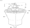
FIG. 1 is a perspective view of a centrifuge vessel according to the present disclosure. -
FIG. 2 is an exploded perspective view of a centrifuge vessel according to the present disclosure. -
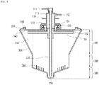
FIG. 3 is a cross-sectional view of a centrifuge vessel taken along line A-A' ofFIG. 1 according to the present disclosure. -
FIG. 4 is a perspective view of aconnection part 100 of a centrifuge vessel according to the present disclosure. -
FIG. 5 is a perspective view of a part of aconnection part 100 of the centrifuge vessel according to the present disclosure. -
FIG. 6 is a cross-sectional perspective view of a part of aconnection part 100 of a centrifuge vessel according to the present disclosure. -
FIGS. 7 and8 are perspective views of a centrifuge vessel of another embodiment of the present disclosure. -
FIGS. 9 and 10 are conceptual views for explaining the characteristics for eliminating the stirring effect of a centrifuge vessel according to the present disclosure. -
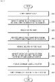
FIG. 11 is a flowchart for explaining an isolation method of SVF using a centrifuge vessel according to the present disclosure. -
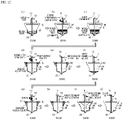
FIG. 12 is a schematic view for explaining an isolation method of SVF using a centrifuge vessel according to the present disclosure. - FIGS. 13 to 15 are the results of a verification test of comparing between SVF isolation using a centrifuge vessel according to the present disclosure and SVF isolation using conventional instruments.
- Hereinafter, a centrifuge vessel according to the present disclosure will be described with reference to the drawings.
- The centrifuge vessel according to the present disclosure is mounted in a centrifuge. The centrifuge generally includes a power member that provides power for rotation, a plurality of bags connected to the centrifuge vessel to accommodate the substances to be separated and the additives, and the separated substances or contaminants therein, a control unit for controlling the operation, a display device for outputting the status of operation, and so on. The centrifuge vessel according to the present disclosure can be applied to any kind of centrifuge, and therefore, the centrifuge will not be redundantly described herein.
- Hereinafter, a centrifuge vessel according to the present disclosure will be described in detail with reference to
FIGS. 1 to 6 . - The centrifuge vessel according to the present disclosure includes a
connection part 100, acover part 200, and abody unit 300. - A
first connection pipe 111, asecond connection pipe 112, a sealingmember housing 113, aconnection pipe housing 115, and a latchingjaw 119 are positioned on an upper portion of theconnection part 100. Although theconnection part 100 is shown in the drawing as including twoconnection pipes - The plurality of
connection pipes connection part 100 are connected to the bags of the centrifuge by separate tubes or the like. With this configuration, the user may be able to feed the analyte or additive into the centrifuge vessel, or remove the separated substance or contaminants out of the centrifuge vessel. - A plurality of
connection pipes body unit 300, and the flow path configuration will be specifically described below. - The sealing
member housing 113 has a sealingmember 130 positioned therein to protect the sealingmember 130 from the outside. The sealingmember 130 may include afirst sealing member 131, asecond sealing member 132, and a third sealing member 133 (seeFIG. 2 ), and may be made of an elastic member, a ceramic member, and a magnetic member, respectively, to increase tightness. - The
connection pipe housing 115 includes a flow path through which a plurality ofconnection pipes body unit 300, and also protects the flow path from the outside. - The
connection pipe housing 115 is configured such that an upper portion and a lower portion are stepped, and thefirst connection pipe 111 is connected to the upper portion and thesecond connection pipe 112 is connected to the lower portion. When the upper and lower portions are stepped, this means that the upper and lower inner diameters of theconnection pipe housing 115 are configured differently from each other, which allows thecenter flow path 120 to be easily inserted into the upper portion, and also allows a protruding portion of theupper plate 150 having the side flow path opening 151 positioned therein to be inserted into the lower portion, and thus allows easy assembly, while maintaining the tightness (seeFIG. 3 ). - The latching
jaw 119 refers to a portion where the centrifuge is latched when the centrifuge vessel is mounted on the centrifuge, and it serves to help the centrifuge vessel to be set in position in the centrifuge. When the centrifuge vessel is mounted for use, user can easily mount the centrifuge by latching the centrifuge to the latchingjaw 119, and can also easily separate the centrifuge by releasing the latchingjaw 119. - The lower portion of the
connection part 100 is inserted into the space within thebody unit 300 and is sealed from the outside by thecover part 200 and the sealingmember 130. Acircular plate 150 is positioned under theconnection part 100. A radial end of theplate 150 is positioned in theside accommodation part 310. In the drawing, theplate 150 is shown as having a circular plane, that is, theplate 150 itself is in a flat cylindrical shape, but any body of revolution may be used. This will be described in detail below. - A
side flow path 152 is provided inside theplate 150 to provide a fluid communication through thesecond connection pipe 112. - One of the advantages of the
plate 150 according to the present disclosure is that theside flow path 152 provided in theplate 150 can be directly connected to theside accommodation part 310. Accordingly, another advantages are obtained such that it is possible to discharge some of the substances sequentially precipitated in theside accommodation part 310 by the centrifugation process through thesecond connection pipe 112, and in the discharge process and the centrifugation process, theplate 150 as a body of revolution does not cause a stirring effect on the solution collected in theside accommodation part 310, so that the outermost precipitate layer not in contact with the discharge port is not stirred. This will be discussed in detail below with reference toFIGS. 9 and 10 . - The
cover part 200 refers to a portion that is seated on the upper portion of thebody unit 300. - An
opening 210 is positioned at an upper center of thecover part 200. Theopening 210 is configured such that the protrusion of theupper plate 150 having the side flow path positioned therein is inserted into and coupled with theopening 210, and thecentral flow path 120 is passed through theopening 210. - A sealing
member seating part 230 is positioned radially outward of theopening 210, and the sealingmember 130 is seated thereon. - A
body connection part 240 protruding upward is positioned radially outward of thecover part 200. A groove is provided on a lower portion of thebody connection part 240 and acover connection part 340 of thebody unit 300 is inserted therein, such that the durability of the centrifuge vessel is increased and separation of thecover part 200 is prevented during rotation. - The
body unit 300 may be divided into anupper body 301, amiddle body 302, and a lower body 303 (seeFIG. 3 ). - The
side accommodation part 310 is positioned radially outward of theupper body 301. Theside accommodation part 310 refers to a portion that protrudes at least radially outward of thebody unit 300. During an operation of the centrifuge, substances separated in the centrifuge vessel begin to be accumulated naturally in theside accommodation part 310 by centrifugal force. When the rotation of the centrifuge is completed, substances of low viscosity will descend by gravity and flow to a loweraccommodating part 330 of thelower body 303, while substance of high viscosity (e.g., SVF) remain in the sideaccommodating part 310. - Preferably, the wall of the
side accommodation part 310 is radially and outwardly protruded and smoothly connected to the wall of thebody unit 300. That is, it is preferable that theupper body 301 and themiddle body 302 are connected smoothly. In this case, substances separated in themiddle body 302 or thelower body 303 can be naturally delivered to theside accommodation part 310 of theupper body 301. While the diameter of themiddle body 302 is shown as being constant inFIG. 3 , the diameter may be different as long as themiddle body 302 is smoothly connected to theupper body 301. - Further, the
side accommodation part 310 extends radially outwards in all directions (that is, by 360 degrees). When only a part of the lobe is extended, it will take the form of the conventional lobe where the SVF is accommodated to some extent. However, when the lobe extends radially outwards in all directions, SVF can be accommodated regardless of directions where the SVF is separated by centrifugation, and as a result, superior yield rate can be expected. - The lower
accommodating part 330 is positioned at an end of thelower body 303 and thecentral flow path 120 is connected to the inside of the loweraccommodating part 330. With this configuration, the substances accumulated in the loweraccommodating part 330 can be discharged to the outside of the centrifuge vessel (seeFIGS. 12c and 12j ). - A plurality of stirring
members 360 are positioned on an inner surface of thelower body 303, i.e., on a bottom surface of thelower body 303. It is preferable that the plurality of stirringmembers 360 are arranged so as to form a plurality of rows toward the center of rotation axis of thebody unit 300.FIG. 2 illustrates fivestirring members 360 in each of three rows, but the number and arrangement may be varied. - Meanwhile, in the illustrated embodiment, the
side accommodation part 310 extending radially outward is positioned in theupper body 301, but another embodiment is also possible in which the side accommodation part is positioned in the middle body or the lower body. In the above case, the plate should also be positioned in the middle body or the lower body where the side accommodation part is positioned. - The flow path of the centrifuge vessel according to the present disclosure will be described with further reference to
FIGS. 3 . As used herein, "flow channel" refers to a fluid communication path between the outside of the centrifuge vessel and the inside of thebody unit 300. - The present disclosure adopts two independent channels.
- The first flow path includes the
first connection pipe 111 and thecentral flow path 120, and the end thereof is positioned at the loweraccommodating part 330. The second flow path includes thesecond connection pipe 112, a radially outer region of the connection pipe housing 115 (that is, an outer region of the central flow path 120), a side flow path opening 151, and aside flow path 152. An end of the second flow path is positioned in theside accommodation part 310. In this example, the side flow path opening 151 is in a shape that is bent at 90 degrees to connect thesecond connection pipe 112 and the side flow path 152 (seeFIGS. 5 and6 ). - The first flow path and the second flow path are independent of each other. In particular, when viewed from the inside of the
connection pipe housing 115, thecentral flow path 120 is positioned nearest to the center, thus constituting the first flow path, and the second flow path is formed on the outside of the wall of thecentral flow path 120 that serves as a boundary. Accordingly, the two flow paths are independent of each other. - The centrifuge vessel according to the present disclosure is advantageous in that the vessel is designed to be easily assembled while having an excellent tightness, thus providing low difficulty of manufacturing and low manufacturing cost.
- The assembling method will be described with reference to
FIG. 2 . - The upper portion of the
connection part 100, which includes the plurality ofconnection pipes connection pipe housing 115, the latchingjaw 119, and the sealingmember housing 113, is integrally molded. - The
first sealing member 131, thesecond sealing member 132, and thethird sealing member 133 are separately molded due to different substances thereof, and then an upper surface of thesecond sealing member 132 is inserted into a lower surface of thefirst sealing member 131 and an upper surface of thethird sealing member 133 is inserted into a lower surface of thesecond sealing member 132 to form anintegrated sealing member 130. - The upper surface of the sealing member 130 (that is, the upper surface of the first sealing member 131) is inserted into the inner surface of the sealing
member housing 113 and the lower surface of the sealing member 130 (that is, the lower surface of the third sealing member 133) is seated on the sealingmember seating part 230 of thecover part 200. In this example, the upper surface of the sealingmember 130 is sized and shaped to fit the inner surface of the sealingmember housing 113, and the lower surface of the sealingmember 130 is sized and shaped to fit the sealingmember seating part 230, such that the sealing is maintained. - Next, the lower portion of the
connection part 100 including thecentral flow path 120 and theplate 150 is inserted into and coupled with the assembly of the upper portion of theconnection part 100, the sealingmember 130 and thecover part 200 from below. Specifically, thecentral flow path 120 is inserted into the upper portion of theconnection pipe housing 115, and the protruding portion of theupper plate 150 where the side flow path opening 151 is positioned is inserted into the lower portion of the connection pipe housing 115 (seeFIG. 3 ). - Next, the
body unit 300 is mounted on thecover part 200. That is, thecover connection part 340 of thebody unit 300 is inserted into a lower portion of thebody connection part 240 of thecover part 200 and fixed in position. A separate adhering or fusing may be further provided for the inserting and fixing. - As shown in
FIGS. 1 to 6 , the centrifuge vessel according to the embodiment of the present disclosure described above has theside accommodation part 310 positioned in the upper portion of themain body 301. - As shown in
FIG. 7 , a centrifuge vessel according to another embodiment of the present disclosure has theside accommodation part 310 positioned in the middle portion of themain body 302. - As shown in
FIG. 8 , a centrifuge vessel according to still another embodiment of the present disclosure has theside accommodation part 310 positioned in the lower portion of themain body 303. - In all of the three embodiments shown in
FIGS. 1 ,7 and8 , theside accommodation part 310 has at least a part extending radially outwards, or preferably, theside accommodation part 310 extends radially outwards in all directions. Further, in all three embodiments, an end of theplate 150 is positioned in theside accommodation part 310. - The characteristic of a centrifuge vessel of eliminating the stirring effect according to the present disclosure will be described below with reference to
FIGS. 9 and 10. FIGS. 9 and 10a illustrate the stirring effect shown in the related art (or in particular, inKorean Patent Publication No. 10-2016-0006076 FIG. 10b illustrates an example of the present disclosure. - In a centrifuge vessel according to the present disclosure, the substance to be separated in the
cover part 200, thebody unit 300 and thebody unit 300 are rotated as the centrifuge is operated. In this situation, the components included in theconnection part 100 are not rotated. That is, thecentral flow path 120, theplate 150, and theside flow path 152 inside theplate 150 included in theconnection part 100 are not rotated. This is because theconnection part 100 is connected to a substance accommodating bag or the like of the centrifuge that supplies the substance through a tube (not shown) or the like. - This is also the case of the related art in which the
plate 150 is not provided, and accordingly, as shown inFIG. 9a , thebody unit 300 and the substance to be separated included therein are rotated, but theside flow path 152 is not rotated when the centrifuge is operated. When the process proceeds to some extent, the substances to be separated are separated into SVF or the like to form a multi-layered structure, and the substances in the multi-layered structure are rotated, but theside flow path 152 is not rotated. - As shown in
FIG. 10a , in a relative observation of this from the perspective of the multiple layers separated, it means that only theside flow path 152 is rotated, while the multiple layers are in a stationary state. Accordingly, theside flow path 152 stirs and disturbs the multiple layers as it is repeatedly dipped into and removed from the multiple separated layers. This causes some of the separated substances including SVF to be re-mixed, which lowers the isolation efficiency. - However, in the embodiment of the present disclosure provided with the
circular plate 150, different aspects are provided. - As shown in
FIG. 10b , in a relative observation from the side of the multiple layers separated, only theplate 150 is rotated, while the multiple layers are in a stationary state. However, only theplate 150 is rotated due to its circular shape, in the same three-dimensional position. That is, the plate is not newly dipped or removed. Accordingly, the multiple layers are not stirred or disturbed, and the stirring effect in which the separated substances including the SVF are re-mixed again is substantially eliminated. - Meanwhile, the
plate 150 for preventing the stirring effect does not necessarily have to be circular, and any shape may be used as long as it is a shape of a body of revolution. As used herein, the "body of revolution" means a figure that always has a constant shape on the cross-section including the rotation axis. - For example, while the
plate 150 is circular inFIG. 10b , the cross-section from the side of the multiple layers is constant as a square. - The
plate 150 may be a body of revolution having a triangular cross-section rather than a rectangular shape. In this case, theplate 150 itself may have a flat conical shape, and the stirring effect is still not occurred, which is preferable. - The
plate 150 may be a body of revolution having a parallelepipedal cross-section. In this case, theplate 150 itself will be of an umbrella shape, and again, the stirring effect is not occurred, which is preferable. - An SVF isolation method using a centrifuge vessel according to the present disclosure will be described below with reference to
FIGS. 11 and12 . -
FIGS. 12a to 12j show the respective steps described with reference toFIG. 11 , in which corresponding reference numerals (S100 to S800) are added at the bottom of each drawing. - The adipose tissue is supplied into the
body unit 300 through the first connection pipe 111 (S100). - Next, washing solution is supplied into the
body unit 300 through thefirst connection pipe 111, and then the centrifuge is operated, rotating and stirring for a predetermined time (S200). Upon completion of the rotating and stirring, the washed adipose tissue and contaminants including blood or the like are separated into upper and lower layers, respectively. The lower layer of the separated contaminants are discharged to the exterior through thecentral flow path 120 whose end is positioned in the loweraccommodating part 330, and removed (S300). - Next, an enzyme such as collagenase for example is supplied and the centrifuge is operated to rotate and stir for a predetermined time (S400). Upon completion of rotating and stirring, the adipose tissue and primary aqueous solution digested by the enzyme are separated radially inwards and outwards, respectively. The digested adipose tissues that are separated radially inwards are discharged to the outside through the
side flow path 152 whose end is positioned in theside accommodation part 310, and removed (S500). - Then the washing solution is additionally supplied to the remaining primary aqueous solution, after which rotating and stirring are performed for a predetermined time (S600). Thus, the secondary aqueous solution and SVF are separated radially inwards and outwards, respectively. The secondary aqueous solution that is separated radially inwards is discharged to the outside through the
side flow path 152 whose end is positioned in theside accommodation part 310, and removed (S700). - Accordingly, only the SVF remains in the
side accommodation part 310, and it is remained positioned in theside accommodation part 310 due to the viscosity of the SVF, that is, the SVF does not descend downward even with its own weight. Accordingly, after a small amount of washing solution is supplied through thefirst connection pipe 111, the centrifuge vessel repeats rotating and stopping. Because the centrifugal force from the rotation causes the washing solution to be spread widely in theside accommodation part 310, by the repeated rotation and stopping, the SVF is precipitated in thelower body 303 by the inertia imparted to the washing solution. Next, the SVF precipitated in thelower body 303 is extracted and collected through the first connection pipe 111 (S800). - Tests were conducted to verify the performance of the centrifuge vessel according to the present disclosure.
- The fat which was aspirated from the abdomen and thigh of 10 male and female adults between the ages of 20 and 40 was introduced into a centrifuge vessel according to the present disclosure, and then SVF was separated according to the method described with reference to
FIGS. 11 and12 . The tests were conducted with first group introduced with 50 ml and the second group introduced with 100 ml. As an enzyme, 50 mg of collagenase was diluted in 50 ml of Hartmann's solution, compared to 50 ml of fat. - The number of obtained cells per 1g of introduced fat (Cells/g), the cell viability (%), and the collagenase activity (PZU/ml), that is, the residual amount of collagenase, were calculated based on the final product obtained according to the method described in
FIGS. 11 and12 . Cell counting for calculating the number of obtained cells and viability was performed using an automated cell counter. - Among the conventional instruments currently available in the market, Multi Station©, Cha-Station©, Lipokitⓒ, and Celution© were selected. The number of obtained cells per 1 g of introduced fat (Cells/g), the cell viability (%), and the collagenase activity (PZU/ml) of each of the instruments are already well known, and accordingly, the corresponding information was compared with the results according to the present disclosure.
- As shown in FIG. 13, it was observed that when the centrifuge vessel according to the present disclosure was used, 2 to 50 times or more cells were obtained as compared to the results obtained from Multi Station©, Cha-Station©, and Lipokitⓒ. However, the number of obtained cells was similar to the results obtained from Celution©.
- As shown in FIG. 14, the viability of the centrifuge vessel according to the present disclosure was very excellent as compared to the results obtained from Lipokit© and Celution©. However, the cell viability of the centrifuge vessel according to the present disclosure was similar or somewhat lower when compared to the results obtained from Multi Station© and Cha-Station©.
- Then the number of obtained cells was compared with the following results.
- Compared with the present disclosure, Multi Station© of the related art exhibited half of the number of obtained cells or less, but the cell viability was somewhat higher. Compared with the present disclosure, Lipokit© and Celution© exhibited similar number of obtained cells, but lower cell viabilitys. That is, the related art exhibited a low viability when a large amount of cells are obtained, and the number of obtained cells was low when the viability was high.
- Therefore, it was confirmed that the present disclosure has excellent cell viability as well as the number of cells obtained, and thus has very excellent final yield rate as compared with the related art.
- As a result of the collagenase activity as shown in FIG. 15, when the centrifuge vessel according to the present disclosure was used, the amount of collagenase residue was about 20% or less of the average value in Multi Station©, Cha-Station©, Lipokitⓒ, and Celution©, thus it was confirmed that it is more stable.
- It will be apparent to those skilled in the art that various modifications and variations can be made to the present disclosure without departing scope of the present disclosure as defined by the following claims and their equivalents. Therefore, the scope of protection of present disclosure is determined by the claims.
Claims (6)
- A centrifuge vessel comprising:a body unit (300) that is rotatable;a cover part (200) that covers the body unit (300); anda connection part (100) provided in the cover part (200) and comprising a plurality of connection pipes (111) and (112) in fluid communication with an inside of the body unit (300),wherein the body unit (300) comprisesa side accommodation part (310) formed on a side surface of the body unit (300) by extending radially outwards in all directions and protruding radially outward of the body unit (300),characterized in thatthe centrifugation vessel comprises a plate (150), said plate (150) being a body of revolution and having a radial end positioned on the side accommodation part (310),wherein a side flow path (152) in fluid communication with one connection pipe (112) of the plurality of connection pipes (111, 112) is provided inside the plate (150),wherein the plate (150) is configured not to rotate when the body unit (300) rotates,wherein an end of the other connection pipe (111) of the connection pipes (111) and (112) reaches the lower body (303) of the body unit (300),wherein the connection part (100) further comprises a connection pipe housing (115),the other connection pipe (111) of the plurality of connection pipes (111) and (112) reaches the lower body (303) of the body unit (300) through a central flow path (120),a part of the central flow path (120) is provided inside the connection pipe housing (115),the one connection pipe (112) is in fluid communication with the side flow path (152) through a space between the connection pipe housing (115) and the central flow path (120), anda side flow path opening (151) connecting a space between the connection pipe housing (115) and the central flow path (120) to the side flow path (152) is disposed at a center of the plate (150),wherein outside of the centrifuge vessel and inside of the side accommodation part (310) are in fluid communication through the connection pipe (112) and the side flow path (152),wherein a substance accommodated in the side accommodation part (310) is discharged to the outside of the centrifuge vessel through the one connection pipe (112) and the side flow path (152), and a substance outside the centrifuge vessel is introduced into the side accommodating part (310),wherein a diameter of an upper portion of the connection pipe housing (115) is smaller than a diameter of a lower portion of the connection pipe housing (115),the central flow path (120) is inserted into and coupled with the upper portion of the connection pipe housing (115), andthe side flow path opening (151) is inserted into and coupled with the lower portion of the connection pipe housing (115).
- The centrifuge vessel according to claim 1, wherein the side accommodation part (310) extends radially outwards of an upper portion, a middle portion, or a lower portion of the body unit (300).
- The centrifuge vessel according to claim 2, wherein the body unit (300) comprises an upper body (301), a middle body (302), and a lower body (303),a diameter of the upper body (301) gradually increases in an upward direction, andthe side accommodating part (310) is a radially outer part of the upper body (301) with an increased diameter.
- The centrifuge vessel according to claim 3, wherein the diameter of the lower body (303) gradually decreases in a downward direction,a plurality of stirring members (360) are positioned on an inner surface of the lower body (303), andthe plurality of stirring members (360) are arranged to form a plurality of rows oriented toward a center of rotation axis of the body unit (300).
- A centrifugation method using the centrifuge vessel according to claim 1, comprising steps of:
separating a substance inside the centrifuge vessel as the body unit (300) is rotated by a rotation of the centrifuge vessel, which is accumulated in the side accommodating part (310), during which the plate (150) is not rotated when the body unit (300) is rotated, thus preventing a stirring effect of the substance that is separated and accumulated in the side accommodating part (310). - An stromal vascular fraction (SVF) isolation method using the centrifugation method according to claim 5, comprising steps of:(a) introducing adipose tissue into the body unit (300) through a first connection pipe (111) of the plurality of connection pipes (111) and (112);(b) supplying the washing solution through the first connection pipe (111) and centrifuging by the centrifugation method to separate the adipose tissue into a washed adipose tissue and a contaminant;(c) removing contaminants from the body unit (300) through the first connection pipe (111);(d) supplying an enzyme through the first connection pipe (111) and centrifuging by the centrifugation method to separate the washed adipose tissue into a digested adipose tissue and a primary aqueous solution;(e) removing the digested adipose tissue from the body unit (300) through the second connection pipe (112) of the plurality of connection pipes (111) and (112);(f) separating a primary aqueous solution into SVF and a secondary aqueous solution by supplying a washing solution through the first connection pipe (111), stirring, and centrifuging by the centrifugal separation method, wherein the SVF is adhered to the side accommodation part (310);(g) removing the secondary aqueous solution from the body unit (300) through the second connection pipe (112);(h) precipitating the SVF adhered to the side accommodating part (310) by inertia to the lower body (303) by supplying a small amount of washing solution through the first connection pipe (111) and then repeating rotating and stopping the centrifuge vessel; and(i) extracting the SVF precipitated in the lower body (303) through the first connection pipe (111).
Applications Claiming Priority (3)
| Application Number | Priority Date | Filing Date | Title |
|---|---|---|---|
| KR20160070331 | 2016-06-07 | ||
| KR1020160129153A KR101736374B1 (en) | 2016-06-07 | 2016-10-06 | A bowl for a centrifuge and method for separation of stromal vascular fraction using the same |
| PCT/KR2016/011685 WO2017213305A1 (en) | 2016-06-07 | 2016-10-18 | Vessel for centrifuge, and svf isolation method using same |
Publications (3)
| Publication Number | Publication Date |
|---|---|
| EP3466542A1 EP3466542A1 (en) | 2019-04-10 |
| EP3466542A4 EP3466542A4 (en) | 2019-11-06 |
| EP3466542B1 true EP3466542B1 (en) | 2022-03-30 |
Family
ID=59048468
Family Applications (1)
| Application Number | Title | Priority Date | Filing Date |
|---|---|---|---|
| EP16904738.8A Active EP3466542B1 (en) | 2016-06-07 | 2016-10-18 | Vessel for centrifuge, and svf isolation method using same |
Country Status (7)
| Country | Link |
|---|---|
| US (1) | US20190299173A1 (en) |
| EP (1) | EP3466542B1 (en) |
| JP (1) | JP6783324B2 (en) |
| KR (1) | KR101736374B1 (en) |
| CN (1) | CN109311008B (en) |
| ES (1) | ES2912916T3 (en) |
| WO (1) | WO2017213305A1 (en) |
Families Citing this family (8)
| Publication number | Priority date | Publication date | Assignee | Title |
|---|---|---|---|---|
| CN115722351B (en) * | 2018-04-02 | 2026-01-06 | 联合技术实验室公司 | Systems and methods for preparing adipose-derived stem cells |
| US10683478B1 (en) * | 2019-05-16 | 2020-06-16 | Shenzhen Eureka biotechnology Co. Ltd | Device and system for processing a liquid sample containing cells |
| KR20210108048A (en) * | 2020-02-25 | 2021-09-02 | (주)시지바이오 | Centrifuging vessel |
| WO2022046026A1 (en) * | 2020-08-24 | 2022-03-03 | Mo Ma | Device and system for processing a liquid sample containing cells |
| JP7640723B2 (en) * | 2020-10-19 | 2025-03-05 | ヨン チョン,ミン | Blood separation tube equipped with a cell activation unit |
| KR102490576B1 (en) * | 2020-10-19 | 2023-01-19 | 전민용 | Blood separate tube with cell activation part |
| WO2024187983A1 (en) * | 2023-03-13 | 2024-09-19 | Sino-Biocan (Shanghai) Biotech Ltd. | Centrifuge devices and separation methods using the centrifuge devices |
| CN116571359B (en) * | 2023-03-13 | 2026-01-27 | 中博瑞康(上海)生物技术有限公司 | Centrifugal device and separation method for centrifugal device |
Family Cites Families (14)
| Publication number | Priority date | Publication date | Assignee | Title |
|---|---|---|---|---|
| US5976388A (en) * | 1997-05-20 | 1999-11-02 | Cobe Cardiovascular Operating Co., Inc. | Method and apparatus for autologous blood salvage |
| EP1057534A1 (en) * | 1999-06-03 | 2000-12-06 | Haemonetics Corporation | Centrifugation bowl with filter core |
| US9144583B2 (en) | 2002-03-29 | 2015-09-29 | Tissue Genesis, Inc. | Cell separation apparatus and methods of use |
| JP2007282552A (en) * | 2006-04-14 | 2007-11-01 | Biomaster Inc | Method for cell separation and system for cell separation |
| US8790519B2 (en) * | 2009-06-16 | 2014-07-29 | Biomet Biologics, Llc | Liquid separation from adipose tissue |
| KR101092683B1 (en) * | 2009-07-08 | 2011-12-09 | 심재훈 | Hot pepper paste containing a sulfur duck and production method thereof |
| KR101316573B1 (en) | 2009-10-27 | 2013-10-15 | 도병록 | System and unit for extracting regenerative cells |
| KR101679671B1 (en) * | 2009-10-27 | 2016-11-28 | 도병록 | System for extracting regenerative cells |
| KR101357160B1 (en) * | 2011-12-14 | 2014-02-17 | 주식회사 휴림바이오셀 | System and method for extracting regenerative cells |
| BR112015010040B1 (en) * | 2012-11-05 | 2020-11-17 | Haemonetics Corporation | continuous flow separation chamber |
| KR101466923B1 (en) * | 2013-01-17 | 2014-12-04 | 주식회사 휴림바이오셀 | Device and System for extracting regenerative cells and Method for extracting regenerative cells using the same |
| KR101667848B1 (en) | 2014-07-08 | 2016-10-19 | (주)시지바이오 | Container for separating stem cells from fattissue and method for separating stem cells from fattissue using the same |
| KR20160070331A (en) | 2014-12-10 | 2016-06-20 | 오상숙 | Clothes storage cover that can hold clothing in various sizes |
| KR101754157B1 (en) | 2015-04-29 | 2017-07-20 | 한국산업기술대학교산학협력단 | Energy storage system and method to improve efficiency of energy by the system |
-
2016
- 2016-10-06 KR KR1020160129153A patent/KR101736374B1/en active Active
- 2016-10-18 US US16/307,446 patent/US20190299173A1/en not_active Abandoned
- 2016-10-18 JP JP2018556835A patent/JP6783324B2/en active Active
- 2016-10-18 ES ES16904738T patent/ES2912916T3/en active Active
- 2016-10-18 EP EP16904738.8A patent/EP3466542B1/en active Active
- 2016-10-18 CN CN201680086546.0A patent/CN109311008B/en active Active
- 2016-10-18 WO PCT/KR2016/011685 patent/WO2017213305A1/en not_active Ceased
Non-Patent Citations (1)
| Title |
|---|
| None * |
Also Published As
| Publication number | Publication date |
|---|---|
| JP6783324B2 (en) | 2020-11-11 |
| ES2912916T3 (en) | 2022-05-30 |
| KR101736374B1 (en) | 2017-05-17 |
| EP3466542A1 (en) | 2019-04-10 |
| WO2017213305A1 (en) | 2017-12-14 |
| CN109311008B (en) | 2021-04-20 |
| JP2019514676A (en) | 2019-06-06 |
| EP3466542A4 (en) | 2019-11-06 |
| CN109311008A (en) | 2019-02-05 |
| US20190299173A1 (en) | 2019-10-03 |
Similar Documents
| Publication | Publication Date | Title |
|---|---|---|
| EP3466542A1 (en) | Vessel for centrifuge, and svf isolation method using same | |
| RU2610591C2 (en) | Density phase separation device (versions) | |
| AU2009225367B2 (en) | Multiple processing chamber set and use thereof | |
| CN105518433A (en) | Body fluid collector, body fluid container, and body fluid collection device | |
| WO2011008836A1 (en) | Method and apparatus for separating biological materials | |
| WO2008048535A2 (en) | Connector for use in single and double breast pumping | |
| CN116571359B (en) | Centrifugal device and separation method for centrifugal device | |
| US11911543B2 (en) | Integrated autotransfusion bowl and the fluid line organizer | |
| WO2016158793A1 (en) | Cell separation device and cell separation system | |
| RU2733517C2 (en) | Method and apparatus for separating and collecting samples | |
| JP6115877B2 (en) | Connection device | |
| CN108587884B (en) | Centrifuge tube | |
| CN214319762U (en) | Exosome extraction element | |
| CN114712698B (en) | Tubing and connectors for blood processing systems | |
| AU2001296599A1 (en) | Multiple processing chamber set and use thereof | |
| KR20140075540A (en) | Fat container | |
| WO2018182378A2 (en) | Container for centrifugation | |
| CN106661527B (en) | Cell separation container, cell separation system and cell separation method | |
| KR101667848B1 (en) | Container for separating stem cells from fattissue and method for separating stem cells from fattissue using the same | |
| CN115125102A (en) | Cell separation device and method | |
| TWI579030B (en) | Cell-separating container, cell-separating system and cell-separating method | |
| CN119588526B (en) | Centrifugal rotor and centrifugal machine | |
| CN105143881A (en) | Bone marrow concentrator | |
| CN216933281U (en) | Urine sampler | |
| WO2024187983A1 (en) | Centrifuge devices and separation methods using the centrifuge devices |
Legal Events
| Date | Code | Title | Description |
|---|---|---|---|
| STAA | Information on the status of an ep patent application or granted ep patent |
Free format text: STATUS: THE INTERNATIONAL PUBLICATION HAS BEEN MADE |
|
| PUAI | Public reference made under article 153(3) epc to a published international application that has entered the european phase |
Free format text: ORIGINAL CODE: 0009012 |
|
| STAA | Information on the status of an ep patent application or granted ep patent |
Free format text: STATUS: REQUEST FOR EXAMINATION WAS MADE |
|
| 17P | Request for examination filed |
Effective date: 20181212 |
|
| AK | Designated contracting states |
Kind code of ref document: A1 Designated state(s): AL AT BE BG CH CY CZ DE DK EE ES FI FR GB GR HR HU IE IS IT LI LT LU LV MC MK MT NL NO PL PT RO RS SE SI SK SM TR |
|
| AX | Request for extension of the european patent |
Extension state: BA ME |
|
| DAV | Request for validation of the european patent (deleted) | ||
| DAX | Request for extension of the european patent (deleted) | ||
| A4 | Supplementary search report drawn up and despatched |
Effective date: 20191009 |
|
| RIC1 | Information provided on ipc code assigned before grant |
Ipc: C12M 1/26 20060101ALI20191003BHEP Ipc: B01F 7/18 20060101ALI20191003BHEP Ipc: C12N 5/071 20100101ALI20191003BHEP Ipc: B01F 7/26 20060101ALI20191003BHEP Ipc: B04B 5/04 20060101ALI20191003BHEP Ipc: C12N 5/0775 20100101ALI20191003BHEP Ipc: A61M 1/36 20060101ALI20191003BHEP Ipc: C12M 1/00 20060101ALI20191003BHEP Ipc: B01L 3/00 20060101AFI20191003BHEP |
|
| STAA | Information on the status of an ep patent application or granted ep patent |
Free format text: STATUS: EXAMINATION IS IN PROGRESS |
|
| 17Q | First examination report despatched |
Effective date: 20200623 |
|
| GRAP | Despatch of communication of intention to grant a patent |
Free format text: ORIGINAL CODE: EPIDOSNIGR1 |
|
| STAA | Information on the status of an ep patent application or granted ep patent |
Free format text: STATUS: GRANT OF PATENT IS INTENDED |
|
| RIC1 | Information provided on ipc code assigned before grant |
Ipc: B04B 11/02 20060101ALI20210920BHEP Ipc: B04B 7/08 20060101ALI20210920BHEP Ipc: B04B 5/04 20060101ALI20210920BHEP Ipc: C12N 5/071 20100101ALI20210920BHEP Ipc: C12N 5/0775 20100101ALI20210920BHEP Ipc: C12M 1/00 20060101ALI20210920BHEP Ipc: C12M 1/26 20060101ALI20210920BHEP Ipc: A61M 1/36 20060101ALI20210920BHEP Ipc: B01L 3/00 20060101AFI20210920BHEP |
|
| INTG | Intention to grant announced |
Effective date: 20211022 |
|
| GRAS | Grant fee paid |
Free format text: ORIGINAL CODE: EPIDOSNIGR3 |
|
| GRAA | (expected) grant |
Free format text: ORIGINAL CODE: 0009210 |
|
| STAA | Information on the status of an ep patent application or granted ep patent |
Free format text: STATUS: THE PATENT HAS BEEN GRANTED |
|
| AK | Designated contracting states |
Kind code of ref document: B1 Designated state(s): AL AT BE BG CH CY CZ DE DK EE ES FI FR GB GR HR HU IE IS IT LI LT LU LV MC MK MT NL NO PL PT RO RS SE SI SK SM TR |
|
| REG | Reference to a national code |
Ref country code: GB Ref legal event code: FG4D |
|
| REG | Reference to a national code |
Ref country code: CH Ref legal event code: EP |
|
| REG | Reference to a national code |
Ref country code: AT Ref legal event code: REF Ref document number: 1478675 Country of ref document: AT Kind code of ref document: T Effective date: 20220415 |
|
| REG | Reference to a national code |
Ref country code: DE Ref legal event code: R096 Ref document number: 602016070641 Country of ref document: DE |
|
| REG | Reference to a national code |
Ref country code: IE Ref legal event code: FG4D |
|
| REG | Reference to a national code |
Ref country code: ES Ref legal event code: FG2A Ref document number: 2912916 Country of ref document: ES Kind code of ref document: T3 Effective date: 20220530 |
|
| REG | Reference to a national code |
Ref country code: LT Ref legal event code: MG9D |
|
| PG25 | Lapsed in a contracting state [announced via postgrant information from national office to epo] |
Ref country code: SE Free format text: LAPSE BECAUSE OF FAILURE TO SUBMIT A TRANSLATION OF THE DESCRIPTION OR TO PAY THE FEE WITHIN THE PRESCRIBED TIME-LIMIT Effective date: 20220330 Ref country code: RS Free format text: LAPSE BECAUSE OF FAILURE TO SUBMIT A TRANSLATION OF THE DESCRIPTION OR TO PAY THE FEE WITHIN THE PRESCRIBED TIME-LIMIT Effective date: 20220330 Ref country code: NO Free format text: LAPSE BECAUSE OF FAILURE TO SUBMIT A TRANSLATION OF THE DESCRIPTION OR TO PAY THE FEE WITHIN THE PRESCRIBED TIME-LIMIT Effective date: 20220630 Ref country code: LT Free format text: LAPSE BECAUSE OF FAILURE TO SUBMIT A TRANSLATION OF THE DESCRIPTION OR TO PAY THE FEE WITHIN THE PRESCRIBED TIME-LIMIT Effective date: 20220330 Ref country code: HR Free format text: LAPSE BECAUSE OF FAILURE TO SUBMIT A TRANSLATION OF THE DESCRIPTION OR TO PAY THE FEE WITHIN THE PRESCRIBED TIME-LIMIT Effective date: 20220330 Ref country code: BG Free format text: LAPSE BECAUSE OF FAILURE TO SUBMIT A TRANSLATION OF THE DESCRIPTION OR TO PAY THE FEE WITHIN THE PRESCRIBED TIME-LIMIT Effective date: 20220630 |
|
| REG | Reference to a national code |
Ref country code: NL Ref legal event code: MP Effective date: 20220330 |
|
| REG | Reference to a national code |
Ref country code: AT Ref legal event code: MK05 Ref document number: 1478675 Country of ref document: AT Kind code of ref document: T Effective date: 20220330 |
|
| PG25 | Lapsed in a contracting state [announced via postgrant information from national office to epo] |
Ref country code: LV Free format text: LAPSE BECAUSE OF FAILURE TO SUBMIT A TRANSLATION OF THE DESCRIPTION OR TO PAY THE FEE WITHIN THE PRESCRIBED TIME-LIMIT Effective date: 20220330 Ref country code: GR Free format text: LAPSE BECAUSE OF FAILURE TO SUBMIT A TRANSLATION OF THE DESCRIPTION OR TO PAY THE FEE WITHIN THE PRESCRIBED TIME-LIMIT Effective date: 20220701 Ref country code: FI Free format text: LAPSE BECAUSE OF FAILURE TO SUBMIT A TRANSLATION OF THE DESCRIPTION OR TO PAY THE FEE WITHIN THE PRESCRIBED TIME-LIMIT Effective date: 20220330 |
|
| PG25 | Lapsed in a contracting state [announced via postgrant information from national office to epo] |
Ref country code: NL Free format text: LAPSE BECAUSE OF FAILURE TO SUBMIT A TRANSLATION OF THE DESCRIPTION OR TO PAY THE FEE WITHIN THE PRESCRIBED TIME-LIMIT Effective date: 20220330 |
|
| PG25 | Lapsed in a contracting state [announced via postgrant information from national office to epo] |
Ref country code: SM Free format text: LAPSE BECAUSE OF FAILURE TO SUBMIT A TRANSLATION OF THE DESCRIPTION OR TO PAY THE FEE WITHIN THE PRESCRIBED TIME-LIMIT Effective date: 20220330 Ref country code: SK Free format text: LAPSE BECAUSE OF FAILURE TO SUBMIT A TRANSLATION OF THE DESCRIPTION OR TO PAY THE FEE WITHIN THE PRESCRIBED TIME-LIMIT Effective date: 20220330 Ref country code: RO Free format text: LAPSE BECAUSE OF FAILURE TO SUBMIT A TRANSLATION OF THE DESCRIPTION OR TO PAY THE FEE WITHIN THE PRESCRIBED TIME-LIMIT Effective date: 20220330 Ref country code: PT Free format text: LAPSE BECAUSE OF FAILURE TO SUBMIT A TRANSLATION OF THE DESCRIPTION OR TO PAY THE FEE WITHIN THE PRESCRIBED TIME-LIMIT Effective date: 20220801 Ref country code: EE Free format text: LAPSE BECAUSE OF FAILURE TO SUBMIT A TRANSLATION OF THE DESCRIPTION OR TO PAY THE FEE WITHIN THE PRESCRIBED TIME-LIMIT Effective date: 20220330 Ref country code: CZ Free format text: LAPSE BECAUSE OF FAILURE TO SUBMIT A TRANSLATION OF THE DESCRIPTION OR TO PAY THE FEE WITHIN THE PRESCRIBED TIME-LIMIT Effective date: 20220330 Ref country code: AT Free format text: LAPSE BECAUSE OF FAILURE TO SUBMIT A TRANSLATION OF THE DESCRIPTION OR TO PAY THE FEE WITHIN THE PRESCRIBED TIME-LIMIT Effective date: 20220330 |
|
| PG25 | Lapsed in a contracting state [announced via postgrant information from national office to epo] |
Ref country code: PL Free format text: LAPSE BECAUSE OF FAILURE TO SUBMIT A TRANSLATION OF THE DESCRIPTION OR TO PAY THE FEE WITHIN THE PRESCRIBED TIME-LIMIT Effective date: 20220330 Ref country code: IS Free format text: LAPSE BECAUSE OF FAILURE TO SUBMIT A TRANSLATION OF THE DESCRIPTION OR TO PAY THE FEE WITHIN THE PRESCRIBED TIME-LIMIT Effective date: 20220730 Ref country code: AL Free format text: LAPSE BECAUSE OF FAILURE TO SUBMIT A TRANSLATION OF THE DESCRIPTION OR TO PAY THE FEE WITHIN THE PRESCRIBED TIME-LIMIT Effective date: 20220330 |
|
| REG | Reference to a national code |
Ref country code: DE Ref legal event code: R097 Ref document number: 602016070641 Country of ref document: DE |
|
| PG25 | Lapsed in a contracting state [announced via postgrant information from national office to epo] |
Ref country code: DK Free format text: LAPSE BECAUSE OF FAILURE TO SUBMIT A TRANSLATION OF THE DESCRIPTION OR TO PAY THE FEE WITHIN THE PRESCRIBED TIME-LIMIT Effective date: 20220330 |
|
| PLBE | No opposition filed within time limit |
Free format text: ORIGINAL CODE: 0009261 |
|
| STAA | Information on the status of an ep patent application or granted ep patent |
Free format text: STATUS: NO OPPOSITION FILED WITHIN TIME LIMIT |
|
| 26N | No opposition filed |
Effective date: 20230103 |
|
| REG | Reference to a national code |
Ref country code: DE Ref legal event code: R119 Ref document number: 602016070641 Country of ref document: DE |
|
| PG25 | Lapsed in a contracting state [announced via postgrant information from national office to epo] |
Ref country code: SI Free format text: LAPSE BECAUSE OF FAILURE TO SUBMIT A TRANSLATION OF THE DESCRIPTION OR TO PAY THE FEE WITHIN THE PRESCRIBED TIME-LIMIT Effective date: 20220330 Ref country code: MC Free format text: LAPSE BECAUSE OF FAILURE TO SUBMIT A TRANSLATION OF THE DESCRIPTION OR TO PAY THE FEE WITHIN THE PRESCRIBED TIME-LIMIT Effective date: 20220330 |
|
| REG | Reference to a national code |
Ref country code: CH Ref legal event code: PL |
|
| REG | Reference to a national code |
Ref country code: BE Ref legal event code: MM Effective date: 20221031 |
|
| GBPC | Gb: european patent ceased through non-payment of renewal fee |
Effective date: 20221018 |
|
| PG25 | Lapsed in a contracting state [announced via postgrant information from national office to epo] |
Ref country code: LU Free format text: LAPSE BECAUSE OF NON-PAYMENT OF DUE FEES Effective date: 20221018 |
|
| P01 | Opt-out of the competence of the unified patent court (upc) registered |
Effective date: 20230527 |
|
| PG25 | Lapsed in a contracting state [announced via postgrant information from national office to epo] |
Ref country code: LI Free format text: LAPSE BECAUSE OF NON-PAYMENT OF DUE FEES Effective date: 20221031 Ref country code: FR Free format text: LAPSE BECAUSE OF NON-PAYMENT OF DUE FEES Effective date: 20221031 Ref country code: DE Free format text: LAPSE BECAUSE OF NON-PAYMENT OF DUE FEES Effective date: 20230503 Ref country code: CH Free format text: LAPSE BECAUSE OF NON-PAYMENT OF DUE FEES Effective date: 20221031 |
|
| PG25 | Lapsed in a contracting state [announced via postgrant information from national office to epo] |
Ref country code: BE Free format text: LAPSE BECAUSE OF NON-PAYMENT OF DUE FEES Effective date: 20221031 |
|
| PG25 | Lapsed in a contracting state [announced via postgrant information from national office to epo] |
Ref country code: IE Free format text: LAPSE BECAUSE OF NON-PAYMENT OF DUE FEES Effective date: 20221018 Ref country code: GB Free format text: LAPSE BECAUSE OF NON-PAYMENT OF DUE FEES Effective date: 20221018 |
|
| PG25 | Lapsed in a contracting state [announced via postgrant information from national office to epo] |
Ref country code: HU Free format text: LAPSE BECAUSE OF FAILURE TO SUBMIT A TRANSLATION OF THE DESCRIPTION OR TO PAY THE FEE WITHIN THE PRESCRIBED TIME-LIMIT; INVALID AB INITIO Effective date: 20161018 |
|
| PG25 | Lapsed in a contracting state [announced via postgrant information from national office to epo] |
Ref country code: CY Free format text: LAPSE BECAUSE OF FAILURE TO SUBMIT A TRANSLATION OF THE DESCRIPTION OR TO PAY THE FEE WITHIN THE PRESCRIBED TIME-LIMIT Effective date: 20220330 |
|
| PG25 | Lapsed in a contracting state [announced via postgrant information from national office to epo] |
Ref country code: MK Free format text: LAPSE BECAUSE OF FAILURE TO SUBMIT A TRANSLATION OF THE DESCRIPTION OR TO PAY THE FEE WITHIN THE PRESCRIBED TIME-LIMIT Effective date: 20220330 |
|
| PG25 | Lapsed in a contracting state [announced via postgrant information from national office to epo] |
Ref country code: TR Free format text: LAPSE BECAUSE OF FAILURE TO SUBMIT A TRANSLATION OF THE DESCRIPTION OR TO PAY THE FEE WITHIN THE PRESCRIBED TIME-LIMIT Effective date: 20220330 |
|
| PG25 | Lapsed in a contracting state [announced via postgrant information from national office to epo] |
Ref country code: MT Free format text: LAPSE BECAUSE OF FAILURE TO SUBMIT A TRANSLATION OF THE DESCRIPTION OR TO PAY THE FEE WITHIN THE PRESCRIBED TIME-LIMIT Effective date: 20220330 |
|
| PGFP | Annual fee paid to national office [announced via postgrant information from national office to epo] |
Ref country code: IT Payment date: 20250924 Year of fee payment: 10 |
|
| PGFP | Annual fee paid to national office [announced via postgrant information from national office to epo] |
Ref country code: ES Payment date: 20251117 Year of fee payment: 10 |