EP3466525A1 - Dehydration system for aqueous organic compounds, operation method therefor, and dehydration method - Google Patents
Dehydration system for aqueous organic compounds, operation method therefor, and dehydration method Download PDFInfo
- Publication number
- EP3466525A1 EP3466525A1 EP17802840.3A EP17802840A EP3466525A1 EP 3466525 A1 EP3466525 A1 EP 3466525A1 EP 17802840 A EP17802840 A EP 17802840A EP 3466525 A1 EP3466525 A1 EP 3466525A1
- Authority
- EP
- European Patent Office
- Prior art keywords
- water
- condenser
- membrane module
- separation membrane
- pressure
- Prior art date
- Legal status (The legal status is an assumption and is not a legal conclusion. Google has not performed a legal analysis and makes no representation as to the accuracy of the status listed.)
- Granted
Links
Images



Classifications
-
- B—PERFORMING OPERATIONS; TRANSPORTING
- B01—PHYSICAL OR CHEMICAL PROCESSES OR APPARATUS IN GENERAL
- B01D—SEPARATION
- B01D61/00—Processes of separation using semi-permeable membranes, e.g. dialysis, osmosis or ultrafiltration; Apparatus, accessories or auxiliary operations specially adapted therefor
- B01D61/36—Pervaporation; Membrane distillation; Liquid permeation
- B01D61/366—Apparatus therefor
-
- B—PERFORMING OPERATIONS; TRANSPORTING
- B01—PHYSICAL OR CHEMICAL PROCESSES OR APPARATUS IN GENERAL
- B01D—SEPARATION
- B01D61/00—Processes of separation using semi-permeable membranes, e.g. dialysis, osmosis or ultrafiltration; Apparatus, accessories or auxiliary operations specially adapted therefor
- B01D61/36—Pervaporation; Membrane distillation; Liquid permeation
-
- B—PERFORMING OPERATIONS; TRANSPORTING
- B01—PHYSICAL OR CHEMICAL PROCESSES OR APPARATUS IN GENERAL
- B01D—SEPARATION
- B01D61/00—Processes of separation using semi-permeable membranes, e.g. dialysis, osmosis or ultrafiltration; Apparatus, accessories or auxiliary operations specially adapted therefor
- B01D61/36—Pervaporation; Membrane distillation; Liquid permeation
- B01D61/362—Pervaporation
-
- B—PERFORMING OPERATIONS; TRANSPORTING
- B01—PHYSICAL OR CHEMICAL PROCESSES OR APPARATUS IN GENERAL
- B01D—SEPARATION
- B01D63/00—Apparatus in general for separation processes using semi-permeable membranes
- B01D63/06—Tubular membrane modules
-
- B—PERFORMING OPERATIONS; TRANSPORTING
- B01—PHYSICAL OR CHEMICAL PROCESSES OR APPARATUS IN GENERAL
- B01D—SEPARATION
- B01D69/00—Semi-permeable membranes for separation processes or apparatus characterised by their form, structure or properties; Manufacturing processes specially adapted therefor
- B01D69/10—Supported membranes; Membrane supports
- B01D69/107—Organic support material
- B01D69/1071—Woven, non-woven or net mesh
-
- B—PERFORMING OPERATIONS; TRANSPORTING
- B01—PHYSICAL OR CHEMICAL PROCESSES OR APPARATUS IN GENERAL
- B01D—SEPARATION
- B01D69/00—Semi-permeable membranes for separation processes or apparatus characterised by their form, structure or properties; Manufacturing processes specially adapted therefor
- B01D69/12—Composite membranes; Ultra-thin membranes
- B01D69/1216—Three or more layers
-
- B—PERFORMING OPERATIONS; TRANSPORTING
- B01—PHYSICAL OR CHEMICAL PROCESSES OR APPARATUS IN GENERAL
- B01D—SEPARATION
- B01D71/00—Semi-permeable membranes for separation processes or apparatus characterised by the material; Manufacturing processes specially adapted therefor
- B01D71/02—Inorganic material
- B01D71/0213—Silicon
-
- B—PERFORMING OPERATIONS; TRANSPORTING
- B01—PHYSICAL OR CHEMICAL PROCESSES OR APPARATUS IN GENERAL
- B01D—SEPARATION
- B01D71/00—Semi-permeable membranes for separation processes or apparatus characterised by the material; Manufacturing processes specially adapted therefor
- B01D71/02—Inorganic material
- B01D71/028—Molecular sieves
-
- C—CHEMISTRY; METALLURGY
- C02—TREATMENT OF WATER, WASTE WATER, SEWAGE, OR SLUDGE
- C02F—TREATMENT OF WATER, WASTE WATER, SEWAGE, OR SLUDGE
- C02F1/00—Treatment of water, waste water, or sewage
- C02F1/008—Control or steering systems not provided for elsewhere in subclass C02F
-
- C—CHEMISTRY; METALLURGY
- C02—TREATMENT OF WATER, WASTE WATER, SEWAGE, OR SLUDGE
- C02F—TREATMENT OF WATER, WASTE WATER, SEWAGE, OR SLUDGE
- C02F1/00—Treatment of water, waste water, or sewage
- C02F1/44—Treatment of water, waste water, or sewage by dialysis, osmosis or reverse osmosis
- C02F1/448—Treatment of water, waste water, or sewage by dialysis, osmosis or reverse osmosis by pervaporation
-
- B—PERFORMING OPERATIONS; TRANSPORTING
- B01—PHYSICAL OR CHEMICAL PROCESSES OR APPARATUS IN GENERAL
- B01D—SEPARATION
- B01D2311/00—Details relating to membrane separation process operations and control
- B01D2311/10—Temperature control
-
- B—PERFORMING OPERATIONS; TRANSPORTING
- B01—PHYSICAL OR CHEMICAL PROCESSES OR APPARATUS IN GENERAL
- B01D—SEPARATION
- B01D2311/00—Details relating to membrane separation process operations and control
- B01D2311/14—Pressure control
-
- C—CHEMISTRY; METALLURGY
- C02—TREATMENT OF WATER, WASTE WATER, SEWAGE, OR SLUDGE
- C02F—TREATMENT OF WATER, WASTE WATER, SEWAGE, OR SLUDGE
- C02F2101/00—Nature of the contaminant
- C02F2101/30—Organic compounds
-
- C—CHEMISTRY; METALLURGY
- C02—TREATMENT OF WATER, WASTE WATER, SEWAGE, OR SLUDGE
- C02F—TREATMENT OF WATER, WASTE WATER, SEWAGE, OR SLUDGE
- C02F2209/00—Controlling or monitoring parameters in water treatment
- C02F2209/02—Temperature
-
- C—CHEMISTRY; METALLURGY
- C02—TREATMENT OF WATER, WASTE WATER, SEWAGE, OR SLUDGE
- C02F—TREATMENT OF WATER, WASTE WATER, SEWAGE, OR SLUDGE
- C02F2209/00—Controlling or monitoring parameters in water treatment
- C02F2209/03—Pressure
Definitions
- the present invention relates to: a dehydration system including a separation membrane module, which is used for separating water from organic solvents in the industrial fields; an operation method of the same; and a dehydration method.
- Separation of water and an organic compound that are contained in an aqueous organic compound is an important technology for purification of aqueous organic compounds in chemical plants as well as recovery of organic compounds from aqueous organic compounds, for example, at precision electronic component factories and lithium battery production plants in the semiconductor industries of printed wiring boards, semiconductor wafers, electronic components, liquid crystal substrates, lenses and the like.
- Distillation has been conventionally employed as a method of dehydrating an aqueous organic compound; however, in recent years, dehydration methods using an inorganic membrane such as a zeolite membrane have been proposed (Patent Documents 1 to 4).
- a pervaporation method in which an aqueous organic compound is brought into contact with one side (e.g., outer side) of a membrane element and the pressure on the other side (e.g., inner side) is reduced so as to allow water to permeate through the membrane element in the form of steam
- a vapor permeation method in which an aqueous organic compound is supplied in a vapor state from the beginning.
- the driving force of water permeation is determined by a difference in water partial pressure between the outer side (the side to which an aqueous organic compound is supplied) and the inner side (the side to which water permeates) of a membrane element.
- a dehydration system in which a separation membrane module is used may be employed as an apparatus for performing dehydration of an aqueous organic compound using a zeolite membrane.
- a tubular membrane element used in this separation membrane module is composed of a tubular porous ceramic support and a zeolite membrane disposed on the support.
- Non-patent Document 1 One example of problems in aqueous organic compound dehydration systems using a separation membrane module equipped with a zeolite membrane as a separation membrane is damage to a membrane element (e.g., Non-patent Document 1). Damage to a membrane element markedly reduces the membrane water selectivity, consequently interfering with the plant operations. Therefore, a countermeasure for suppressing damage to a membrane element is demanded in such dehydration systems.
- Non-patent Document 1 Third Technical/Research Workshop on Application of Membrane Separation to Chemical Processes "Aiming at Technology for Applying Membrane Separation to Chemical Processes: Development of High-Performance Separation Membranes and Forefront of Reaction Membrane Separation", held by Chugoku Economic Federation , etc.; lecture material (" Trouble Cases in Practical Application of Zeolite Membrane"), September 5, 2014
- Non-patent Document 1 In order to solve the above-described problem of damage to a membrane element in dehydration systems using a separation membrane module, generally, the strength of the membrane element is increased as a countermeasure (Non-patent Document 1). Meanwhile, there can be found no case where the cause of damage to a membrane element was investigated in terms of device design or operation method of a dehydration system, particularly defects in a pipe for water vapor permeating through a membrane element or in a condensed water extraction sequence.
- an object of the present invention is to provide: a dehydration system including a zeolite membrane-equipped separation membrane module used for separating water from an aqueous organic compound, in which damage to a membrane element in the separation membrane module can be reduced; and an operation method of the same.
- the present inventor intensively studied to solve the above-described problem and consequently discovered that damage to a membrane element in a dehydration system including a zeolite membrane-equipped separation membrane module is caused by backflow of condensed water, which is generated by condensation of water vapor permeating through the membrane element in a vacuum pipe, into the membrane element.
- the cause of the backflow resides in a pipe connecting the membrane element and a condenser or in a defect of the vacuum pipe and/or condensed water extraction sequence, thereby completing the present invention.
- the dehydration system in the operation of a dehydration system including a zeolite membrane-equipped separation membrane module in a chemical plant, the dehydration system is generally assumed to be automatically and continuously operated outdoors regardless of the season and the time of day. In such a case, particularly in winter nights and the like, water vapor permeating through a membrane element is in a state where it is easily condensed in a vacuum pipe.
- the present invention provides a countermeasure against such condensed water.
- embodiments of the present invention include the followings.
- a dehydration system that can be stably operated for a long period and a dehydration method, in which the occurrence of damage to a membrane element caused by condensed water generated in a pipe connecting a separation membrane module and a condenser is suppressed, as well as a method of stably operating the dehydration system for a long period, are provided.
- One embodiment of the present invention is a dehydration system for separating water from an aqueous organic compound, the dehydration system including: a separation membrane module inside of which one or plural tubular membrane elements, each including a tubular porous ceramic support and a zeolite membrane disposed on the support, are arranged and which separates water from the aqueous organic compound supplied thereto using the one or plural tubular membrane elements; a pressure-reducing means for reducing the pressure on a water permeate side of each tubular membrane element; and a condenser which is arranged between the separation membrane module and the pressure-reducing means via a pipe and condenses water vapor permeating through the tubular membrane element (s) into water, wherein the dehydration system has at least one of the following configurations (1) and (2).
- the "pipe connecting the separation membrane module and the condenser” may be hereinafter referred to as a "transmission pipe”.
- the dehydration system of this embodiment is characterized by having at least one of the configurations (1) and (2).
- Examples of technical ideas common to the configurations (1) and (2) include inhibition of generation of condensed water in the pipe (transmission pipe) connecting the separation membrane module and the condenser of the dehydration system, and inhibition of backflow of condensed water generated in the transmission pipe into the separation membrane module.
- the term "damage to a membrane element” means a state where a defect such as cracking or breakage occurs in either or both of the tubular porous ceramic support and the zeolite membrane that constitute a membrane element and the water permeation selectivity of the membrane element is thereby reduced.
- the configurations (1) and (2) can each contribute to the inhibition of generation and backflow of condensed water in the transmission pipe and, particularly, by adopting the configuration (1), the pipe can be maintained at the saturated water vapor temperature or higher, so that generation of condensed water particularly in the transmission pipe can be inhibited.
- the phrase "arranged downward from a permeated water outlet of the separation membrane module toward the condenser" means any state where the condenser is positioned lower than the permeated water outlet of the separation membrane module and the transmission pipe is connected such that it is not positioned higher than the permeated water outlet of the separation membrane module; however, for avoidance of backflow, it is preferred that at least a part of the transmission pipe that is immediate to the permeated water outlet of the separation membrane module be arranged as vertical as possible.
- the thickness (inner diameter) of the transmission pipe may be selected as appropriate taking into consideration, for example, the length of the pipe, the aqueous organic compound to be treated (e.g., the type, the water content, the treatment amount and the like), other equipments in the dehydration system (e.g., the condenser, the pressure-reducing means and the like), and the presence or absence of other dehydration equipment; however, since condensed water is likely to be generated when the thickness (inner diameter) of the transmission pipe is small, the thickness (inner diameter) of the transmission pipe is preferably not less than 2 cm, more preferably not less than 2.5 cm.
- the dehydration system of this embodiment has at least the configuration (1) and includes, as the above-described temperature-maintaining means, an insulating member which covers the pipe connecting the separation membrane module and the condenser.
- the dehydration system of this embodiment has at least the configuration (1) and includes, as the above-described temperature-maintaining means, a heating means for heating the pipe connecting the separation membrane module and the condenser.
- the dehydration system of this embodiment includes both the insulating member and the heating means as the temperature-maintaining means.
- a heating method is not particularly restricted and, for example, a steam trace (steam pipe) or a heating wire of a heat transfer heater (electrical trace) may be wound around the transmission pipe.
- a steam trace steam pipe
- a heating wire of a heat transfer heater electrical trace
- the dehydration system of this embodiment have both of the configurations (1) and (2).
- the method of operating the dehydration system of this embodiment is a method of operating the above-described dehydration system, which method includes maintaining the temperature of the pipe (transmission pipe) connecting the separation membrane module and the condenser to be 20°C or higher.
- the temperature of the transmission pipe is preferably 40°C or higher, more preferably 60°C or higher, still more preferably 80°C or higher, yet still more preferably 100°C or higher, particularly preferably 110°C or higher, most preferably 120°C or higher.
- the temperature of the pipe to be in a range of -20°C to 20°C with respect to a preset temperature of the separation membrane module.
- the dehydration system of this embodiment can be utilized as an alternative means to a conventional dehydration equipment such as a distillation column, or as a means for post-processing of other dehydration equipment such as a distillation column.
- a conventional dehydration equipment such as a distillation column
- a means for post-processing of other dehydration equipment such as a distillation column.
- an aqueous organic compound recovered from a distillation column arranged for a process preceding the separation membrane module may be supplied to the dehydration system.
- the conditions for operating the distillation column and the dehydration system of the present invention may be determined as appropriate taking into consideration the type, the water content and the like of the aqueous organic compound to be treated.
- the aqueous organic compound to be dehydrated and concentrated by the dehydration system of this embodiment is not particularly restricted, and examples thereof include aqueous organic compounds such as aqueous organic acids, aqueous alcohols, and aqueous organic solvents. More specific examples of the aqueous organic compound include aqueous organic acids, such as citric acid, succinic acid, ethylenediamine tetraacetic acid, tartaric acid, salicylic acid, oxalic acid, acetic acid, formic acid, propionic acid, butyric acid, valeric acid, caproic acid, enanthic acid, caprylic acid, benzoic acid, acrylic acid, adipic acid, malonic acid, malic acid, phthalic acid, glycolic acid, terephthalic acid and fumaric acid; phenols; alcohols, such as methyl alcohol, ethyl alcohol, propyl alcohol, isopropyl alcohol, butyl alcohol, isobutyl alcohol, s-but
- the water content in the aqueous organic compound to be treated is not particularly restricted, and the dehydration system of this embodiment can be applied to, for example, an aqueous organic compound having a water content of 5% by weight or higher.
- PV method pervaporation method
- VP method vapor permeation method
- FIG. 1 is a schematic view illustrating a dehydration system based on a PV method, which is one example of the aqueous organic compound dehydration system of this embodiment.
- a raw material organic compound as a raw material is distilled in a distillation column 11, and a low-boiling-point component is discharged from the top of the column via a pipe P 1 ', while a high-boiling-point component (liquid component) is supplied from the bottom of the column to a separation membrane module 10 via a pipe P 1 .
- a high-boiling-point component liquid component
- an aqueous organic compound constituting this high-boiling-point component is exemplified as a treatment subject; however, an aqueous organic compound constituting a liquid component obtained after condensation of the low-boiling-point component discharged via the pipe P 1 ' may be the treatment subject as well.
- tubular membrane elements Inside the separation membrane module 10, one or plural tubular membrane elements (see FIG. 4 ), each having a tubular porous ceramic support and a zeolite membrane disposed on the support, are arranged. Each tubular membrane element has a separation membrane (zeolite membrane) which does not allow an organic compound to permeate therethrough but selectively allows water to permeate therethrough.
- separation membrane zeolite membrane
- an aqueous organic compound is brought into contact with the outer surface of each tubular membrane element and the pressure on the inner surface side is reduced by a pressure-reducing means to allow water to permeate from the outer surface to the inner surface of the membrane element, whereby the organic compound is concentrated and water is recovered.
- a heating means (not illustrated) is arranged in the separation membrane module 10.
- the membrane element may be of a single-tube type or a multi-tube type, and it is preferred that usually 1 to 2, 000, particularly 50 to 1, 000 membrane elements be arranged apart from one another by a distance of 5 mm to 10 mm.
- the housing size and the number of the membrane elements are changed as appropriate in accordance with the amount of a fluid to be treated. A concrete configuration of the membrane elements is described below.
- the aqueous organic compound thus dehydrated and concentrated without permeating through the membrane element(s) is discharged via a pipe P 2 and then circulated back to the distillation column 11 via a pipe P 2A during a period when the water content is equal to or higher than a reference value, or recovered as a dehydrated organic compound via a pipe P 2B when the water content is equal to or lower than the reference value.
- a condenser 12 In the downstream of the separation membrane module 10, a condenser 12, a water storage tank 13 and a vacuum pump 14 are arranged in series, and water (steam) permeated through the separation membrane(s) in the membrane element(s) is condensed by the condenser 12 and subsequently sent to and retained in the water storage tank 13.
- the retained water is discharged from the bottom of the water storage tank 13 once the amount of the retained water reaches a prescribed level.
- a reduction in pressure on the permeate side that is required as a driving force of water permeating through the membrane(s) is attained by the vacuum pump 14 used as a pressure-reducing means, and the degree of vacuum is controlled by a pressure control valve (not illustrated) arranged in the middle of the pipe.
- a pipe P 3 (transmission pipe) connecting the separation membrane module 10 and the condenser 12 is covered by an insulating member 15 as a temperature-maintaining means, and a steam trace is wound as a heating means on the outer wall of the pipe P 3 , although this is not illustrated in the drawing.
- the insulating member 15 and the steam trace are temperature-maintaining means for inhibiting generation of condensed water caused by condensation of water vapor discharged from the separation membrane module 10 in the pipe P 3 . That is, it is satisfactory as long as the pipe P 3 (transmission pipe) can be maintained to have a temperature at which generation of condensed water can be inhibited.
- the temperature of the pipe P 3 is preferably 40°C or higher, more preferably 60°C or higher, still more preferably 80°C or higher, yet still more preferably 100°C or higher, particularly preferably 110°C or higher, most preferably 120°C or higher.
- the temperature of the pipe P 3 (transmission pipe) is preferably adjusted to be in a range of -20°C to 20°C with respect to a preset temperature of the separation membrane module 10.
- the pipe P 3 (transmission pipe) is preferably heated continuously; however, even if the heating of the pipe P 3 (transmission pipe) is temporarily discontinued for some reason, the temperature can be maintained by the insulating member 15.
- the insulating member 15 is composed of, for example, a common heat-insulating material such as glass wool or rock wool, and is arranged in such a manner to cover the pipe P 3 (transmission pipe) . It is preferred that the insulating member 15 cover the pipe P 3 with as little gap as possible. A gap therebetween may lead to the absence of heating by the heating means, or may cause generation of condensed water due to insufficient heating.
- the stream trace may be wound on the pipe P 3 with or without a gap as long as the steam trace can heat the pipe P 3 to a prescribed temperature.
- heated steam of other system in a chemical plant may also be used.
- heating means e.g., a heat transfer heater
- other heating means e.g., a heat transfer heater
- the pipe P 3 (transmission pipe) is arranged downward from a permeated water outlet of the separation membrane module 10 toward the condenser 12.
- the pipe P 3 transmission pipe
- the pipe P 3 is arranged such that a part thereof immediate to the permeated water outlet (outlet of permeated water vapor) of the separation membrane module 10 is arranged along the vertical direction. This configuration is preferred since it enables to more reliably inhibit backflow into the separation membrane module 10 even when condensed water is generated in the pipe P 3 (transmission pipe) due to failure or the like of the temperature-maintaining means.
- a dehydration system having a separation membrane module is used in a PV method of treating a liquid-form aqueous organic compound supplied from a distillation column; however, the dehydration system of this embodiment may also be used in a VP method.
- a PV method is generally employed when a liquid (feed liquid) of an aqueous organic compound such as an aqueous organic acid, an aqueous alcohol or an aqueous organic solvent that is recovered from the bottom and/or the middle of the distillation column is supplied to the separation membrane module, while a VP method is generally employed when a gas of an aqueous organic compound such as an aqueous organic acid, an aqueous alcohol or an aqueous organic solvent that is recovered from the top and/or the middle of the distillation column is supplied to the separation membrane module.
- the dehydration system has a single separation membrane module; however, the dehydration system may have plural separation membrane modules arranged in series or in parallel as well. Moreover, in the above-described embodiments, a distillation column is used; however, a raw material organic compound may be directly supplied to the dehydration system having the separation membrane module.
- the pipe P 3 (transmission pipe) is configured such that it includes the temperature-maintaining means and is arranged downward from the permeated water outlet of the separation module toward the condenser; however, the pipe P 3 (transmission pipe) may also be configured to have either one of these configurations. Still, from the standpoint of inhibiting generation of condensed water per se, it is preferred that the pipe P 3 (transmission pipe) have at least the temperature-maintaining means.
- the present invention also relates to, as another embodiment, a method of operating a dehydration system for separating water from an aqueous organic compound
- the dehydration system includes: a separation membrane module inside of which one or plural tubular membrane elements, each including a tubular porous ceramic support and a zeolite membrane disposed on the support, are arranged and which separates water from the aqueous organic compound supplied thereto using the one or plural tubular membrane elements; a pressure-reducing means for reducing the pressure on a water permeate side of each tubular membrane element; a condenser which is arranged between the separation membrane module and the pressure-reducing means via a pipe and condenses water vapor permeating through the tubular membrane element (s) into water; and a water storage vessel in which water permeating through the condenser is retained, and the method includes controlling the pressure in the pipe connecting the separation membrane module and the condenser to be an absolute pressure of 20 kPa or less when water retained in the water storage vessel is discharged (
- the "pipe connecting the separation membrane module and the condenser” may be hereinafter referred to as a "transmission pipe” .
- the operation method of this embodiment is characterized by controlling the pressure in the pipe connecting the separation membrane module and the condenser to be an absolute pressure of 20 kPa or less when water retained in the water storage vessel is discharged.
- the membrane element(s) is/are highly likely to be damaged in the case of, for example, removing water from an aqueous organic compound having a high temperature (e.g., about 130°C).
- the dehydration system include a pressure control member which is arranged on a pipe connecting the condenser and the water storage vessel and can be opened and closed, and that the pressure in the pipe connecting the separation membrane module and the condenser is controlled by initially closing the pressure control member when water is discharged from the water storage vessel.
- the phrase "initially closing the pressure control member” means to at least close the pressure control member before performing an operation of cancelling a reduced-pressure state of the water storage vessel.
- a vacuum state on the permeate side of the separation membrane module is maintained by closing the pressure control member before introducing a gas into the water storage vessel.
- the pressure of the permeate side is gradually increased; however, by monitoring the pipe between the separation membrane module and the condenser and controlling the pressure control member under such a condition that does not allow the pressure to exceed an absolute pressure of 20 kPa, the pressure between the separation membrane and the condenser as well as between the condenser and the pressure control member can be maintained in a certain range at all times, and damage to the membrane element (s) caused by pressure fluctuation can thereby be suppressed.
- opening the pressure control member in the end means to at least open the pressure control member after performing an operation of bringing the water storage vessel into a reduced-pressure state.
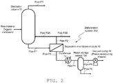
- FIG. 2 is a schematic view illustrating a dehydration system of an aqueous organic compound, which is one embodiment of the present invention and used for a PV method where damage to a membrane element is suppressed by controlling the above-described pressure to be not higher than a specific pressure.
- FIG. 3 is an enlarged schematic view illustrating a section between a separation membrane module and a pressure-reducing means. In FIG. 2 , the section between the separation membrane module and the pressure-reducing means is illustrated in a simple manner.
- a raw material organic compound is distilled in a distillation column 11, and a low-boiling-point component is discharged from the top of the column via a pipe P 1 ', while a high-boiling-point component (liquid component) is supplied from the bottom of the column to a separation membrane module 10 via a pipe P 1 .
- an aqueous organic compound constituting this high-boiling-point component is exemplified as a treatment subject; however, an aqueous organic compound constituting a liquid component obtained after condensation of the low-boiling-point component discharged via the pipe P 1 ' may be the treatment subject as well.
- tubular membrane elements each having a tubular porous ceramic support and a zeolite membrane disposed on the support are arranged.
- Each tubular membrane element has a separation membrane (zeolite membrane) which does not allow an organic compound to permeate therethrough but selectively allows water to permeate therethrough.
- an aqueous organic compound is brought into contact with the outer surface of each tubular membrane element and the pressure of the inner surface side is reduced by a pressure-reducing means to allow water to permeate from the outer surface to the inner surface of the membrane element, whereby the organic compound is concentrated and water is recovered.
- a heating means (not illustrated) is arranged in the separation membrane module 10.
- the membrane element may be of a single-tube type or a multi-tube type, and it is preferred that usually 1 to 2, 000, particularly 50 to 1, 000 membrane elements be arranged apart from one another by a distance of 5 mm to 10 mm.
- the housing size and the number of the membrane elements are changed as appropriate in accordance with the amount of a fluid to be treated. A concrete configuration of the membrane elements is described below.
- the aqueous organic compound thus dehydrated and concentrated without permeating through the membrane element(s) is discharged via a pipe P 2 and then circulated back to the distillation column 11 via a pipe P 2A when the water content is equal to or higher than a reference value, or recovered as a dehydrated organic compound via a pipe P 2B when the water content is equal to or lower than the reference value.
- a condenser 12 In the downstream of the separation membrane module 10, a condenser 12, a water storage vessel 13A and a vacuum pump 14 are arranged in series, and water (steam) permeated through the separation membrane(s) of the membrane element(s) is condensed in the condenser 12 and subsequently sent to and temporarily retained in the water storage vessel 13A. Once the amount of the retained water reaches a prescribed level, the retained water is discharged from the bottom of the water storage vessel 13A and sent to a water storage vessel 13B via a pipe.
- the water storage vessel 13B is larger than the water storage vessel 13A and is thus capable of retaining a greater amount of water.
- a reduced pressure on the permeate side that is required as a driving force of water permeating through the membrane(s) is provided by the vacuum pump 14 used as a pressure-reducing means, and the degree of vacuum is controlled by valves V 1 to V 4 , which are pressure control members arranged in the middle of the respective pipes.
- valves V 1 and V 4 are opened (valves V 2 and V 3 are closed) and, once water retained in the water storage vessel 13A reached a prescribed amount, the valve V 1 is closed first. Then, the valve V 4 is closed and the valves V 2 and V 3 are opened to expose the water storage vessel 13A to the atmosphere, whereby water retained in the water storage vessel 13A is transferred to the water storage vessel 13B. It is noted here that, after the valve V 1 is closed, the operations of opening or closing the valves V 2 , V 3 and V 4 are performed simultaneously; however, these operations may also be performed with a time lag.
- water retained in the water storage vessel 13A is transferred to the water storage vessel 13B by exposing the water storage vessel 13A to the atmosphere; however, a gas other than the atmosphere may be introduced into the water storage vessel 13A to cancel a reduced-pressure state.
- the water storage vessel 13B usually has atmospheric pressure, it may have a reduced pressure as well.
- valves V 1 to V 4 are operated substantially simultaneously without any particular control; however, in the operation method of this embodiment, these valves are operated such that the pressure in the pipe (pipe P 3 ) connecting the separation membrane module 10 and the condenser 12 is controlled to be an absolute pressure of 20 kPa or less.
- valves V 1 and V 4 are in an opened state while the valves V 2 and V 3 are in a closed state, and the absolute pressure on the permeate side of the separation membrane module is 0.5 to 15 kPa or so, with the pressure in the pipe P 3 that connects the separation membrane module 10 and the condenser 12 also being the same.
- the valves V 1 and V 4 are closed when water is discharged from the water storage vessel 13A; however, since there is still a difference in water partial pressure between the outside and the inside of each membrane element in the separation membrane module, the pressure on the permeate side gradually increases with time.
- the pipe P 3 is monitored so as to perform the discharge of water from the water storage vessel 13A (operations of the valves V 2 and V 3 ), the recovery of a degree of vacuum in the water storage vessel 13A (operation of the valve V 4 ) and the recovery of a degree of vacuum in the pipe P 3 (corresponding to the pressure on the permeate side) (operation of the valve V 1 ), all under such a condition where the absolute pressure in the pipe P 3 does not exceed 20 kPa.
- the time required for the absolute pressure in the pipe P 3 to reach 20 kPa after closing of the valve V 1 is dependent on the degree of vacuum during the operation, the aqueous organic compound to be treated (ant its water content), the separation membrane module (membrane element(s) constituting the module), the inner volume of the pipe P 3 and the like and thus cannot be generalized; however, it is usually 1 to 3 minutes or so.
- the inner volume of the water storage vessel 13A, the amount of water to be retained until discharge, the output of the vacuum pump 14 and the like are set as appropriate such that the discharge of water from the water storage vessel 13A and the recovery of a degree of vacuum can be performed during the above-describe period.
- valve V 1 As described above as one example of concrete conditions, after water is discharged from the water storage vessel 13A, it is preferred to open the valve V 1 in the end at the time of reducing the pressure in the water storage vessel 13 and the pipe P 3 .
- opening the valve V 1 after the water storage vessel 13A and the pipe P 3 are brought into a desired reduced-pressure state, since the pressure between the separation membrane module and the condenser as well as between the condenser and the valve V 1 is maintained in a certain range at all times, damage to the membrane elements caused by pressure fluctuation can be suppressed.
- another embodiment of the present invention which is a dehydration method of separating water from an aqueous organic compound, includes, at least: a separation membrane module inside of which one or plural tubular membrane elements, each including a tubular porous ceramic support and a zeolite membrane disposed on the support, are arranged and which separates water from the aqueous organic compound supplied thereto using the one or plural tubular membrane elements; a pressure-reducing means for reducing the pressure on a water permeate side of each tubular membrane element; a condenser which is arranged between the separation membrane module and the pressure-reducing means via a pipe and condenses water vapor permeating through the tubular membrane element(s) into water; and a backflow-inhibiting means for inhibiting backflow of the thus condensed water into the membrane element(s).
- the backflow-inhibiting means has at least one of the following configurations (1) and (2):
- the backflow-inhibiting means includes a water storage vessel in which water permeating through the condenser is retained, and controls the pressure in the pipe connecting the separation membrane module and the condenser to be an absolute pressure of 20 kPa or less when water retained in the water storage vessel is discharged.
- membrane element arranged inside the separation membrane module in the dehydration system of the present invention will now be described. It is noted here that the below-described membrane element represents a preferred mode of the membrane element used in the dehydration system of the present invention, and the membrane element is not restricted to the following as long as the object of the present invention is not impaired.
- a membrane element 1 used in this embodiment that is illustrated in FIG. 4 has a zeolite membrane on (the outer side of) a tubular porous ceramic support and assumes a tubular shape as a whole.
- the "tubular shape” is not restricted to a cylindrical shape and may be a rectangular tube shape; however, from the standpoint of improving the sealing property, the membrane element 1 preferably has a cylindrical (tubular) shape.
- FIGs. 4(A) and 4(B) illustrate one example of the membrane element 1.
- FIG. 4(A) is a drawing that schematically illustrates the outer appearance of the membrane element 1
- FIG. 4(B) is a drawing that schematically illustrates a IIB-IIB cross-section of FIG. 4 (A) .
- the membrane element 1 has a cylindrical porous ceramic support 1a and a zeolite membrane 1b formed on the outer side (outer wall surface) of the porous ceramic support 1a.
- the membrane element 1 illustrated in FIG. 4 which has the zeolite membrane only on the outer wall of the porous ceramic support is used; however, it is also possible to use a membrane element which has a zeolite membrane only on the inner wall or on both the inner wall and the outer wall of a porous ceramic support.
- the porous ceramic support 1a functions as a support that supports the zeolite membrane 1b.
- the material constituting the porous ceramic support 1a is not particularly restricted and may be any chemically stable porous inorganic substance as long as zeolite can be crystallized on its surface or the like in a membrane form.
- Specific examples of such a material include sintered ceramics, such as silica, ⁇ -alumina, ⁇ -alumina, mullite, zirconia, titania, yttria, silicon nitride, and silicon carbide.
- aluminas such as ⁇ -alumina and ⁇ -alumina, and mullite are preferred, and aluminas are particularly preferred.
- the porous ceramic support 1a itself is not required to have a molecular sieving capability.
- fine pores holes, voids
- any known porous ceramic support can be used.
- the porous ceramic support 1a has a porosity of usually 20% or higher, preferably 25% or higher, more preferably 30% or higher, but usually 80% or lower, preferably 60% or lower, more preferably 50% or lower, and the average pore size of the porous ceramic support 1a is usually 0.01 ⁇ m or larger, preferably 0.05 ⁇ m or larger, more preferably 0.1 ⁇ m or larger, with the upper limit thereof being usually 20 ⁇ m or smaller, preferably 10 ⁇ m or smaller, more preferably 5 ⁇ m or smaller.
- the porous ceramic support 1a having such pores not only has a sufficient strength and can appropriately support the zeolite membrane 1b, but also can allow molecules passed through the zeolite membrane 1b to permeate therethrough at a sufficient rate or allow molecules to reach the zeolite membrane 1b at a sufficient rate. Moreover, the porous ceramic support 1a is not easily broken even when a pressure is applied thereto from a sealing member by caulking.
- the porosity and the pore size of the porous ceramic support 1a can be easily determined by mercury porosimetry, SEM observation of a cross-section, or the like. The same also applies to the average pore size; however, the average pore size can also be calculated from the volume and the mass using the true specific gravity.
- the thickness of the porous ceramic support 1a is not particularly restricted as long as the porous ceramic support 1a has a prescribed strength.
- the thickness varies depending on the material, the porosity and the like; however, the thickness is, for example, preferably not less than 0.5 mm, more preferably not less than 0.8 mm, still more preferably not less than 1.3 mm.
- the inner diameter of the porous ceramic support 1a is also not particularly restricted as long as the porous ceramic support 1a has a prescribed strength.
- the inner diameter varies depending on the material, the porosity and the like; however, the ratio of the inner diameter with respect to the thickness of the porous ceramic support 1a (inner diameter (mm)/thickness (mm)) is, for example, preferably not higher than 20, more preferably not higher than 17, still more preferably not higher than 13, particularly preferably not higher than 9.
- the length (length in the axial direction) of the porous ceramic support 1a is also not particularly restricted.
- the zeolite membrane 1b is a thin layer formed on the outer side (outer surface) of the porous ceramic support 1a.
- the mode of the zeolite membrane 1b is not particularly restricted as long as it can appropriately exhibit molecular sieving capability.
- the zeolite membrane 1b is preferably composed of an aluminosilicate; however, as long as the membrane performance is not greatly impaired, a metal element such as Ga, Fe, B, Ti, Zr, Sn or Zn may be used in place of Al, or the zeolite membrane 1b may also contain an element such as Ga, Fe, B, Ti, Zr, Sn, Zn or P along with Al.
- the skeleton of crystal zeolite constituting the pores of the zeolite membrane is preferably an 8 or less-membered oxygen ring, more preferably a 6 to 8-membered oxygen ring.
- zeolite examples include AEI, AFG, ANA, CHA, DDR, EAB, ERI, ESV, FAR, FRA, GIS, ITE, KFI, LEV, LIO, LOS, LTA, LTN, MAR, PAU, RHO, RTH, SOD, STI, TOL, and UFI.
- a membrane constituted by AEI, CHA, DDR, ERI, KFI, LEV, PAU, RHO, RTH, SOD, LTA or UFI-type zeolite it is more preferred to use a membrane constituted by CHA, DDR, RHO or SOD-type zeolite.
- n represents the number of oxygen atoms in a pore having the largest number of oxygen atoms among the pores constituted by a zeolite skeleton and an element T (non-oxygen element constituting the skeleton).
- an organic template (structure-directing agent) may be used as required, and the template is usually not particularly restricted as long as it can yield a desired zeolite structure. It is not necessary to use a template when the zeolite membrane 1b can be synthesized without a template.
- the thickness of the zeolite membrane 1b is not particularly restricted; however, it is usually 0.01 ⁇ m to 30 ⁇ m, preferably 0.01 ⁇ m to 10 ⁇ m. The thinner the zeolite membrane 1b, the more preferred it is, as long as the membrane performance is not greatly impaired.
- Examples of a method of forming the zeolite membrane 1b on the surface of the porous ceramic support 1a include a method of crystallizing zeolite in a membrane form on the surface of the porous ceramic support 1a (see, for example, WO 2013/125660 ).
- FIG. 4 a mode in which the zeolite membrane 1b is formed on the outer wall of the porous ceramic support 1a is illustrated; however, the present invention is not restricted to this mode.
- a mode in which the zeolite membrane 1b is formed on the inner wall of the porous ceramic support 1a, or a mode in which the zeolite membrane 1b is formed on both the outer wall and the inner wall of the porous ceramic support 1a, may be adopted as well.
- the dehydration system is suitable for applications where steady operation is required over a long period (e.g., chemical plants).
Landscapes
- Chemical & Material Sciences (AREA)
- Engineering & Computer Science (AREA)
- Water Supply & Treatment (AREA)
- Chemical Kinetics & Catalysis (AREA)
- Life Sciences & Earth Sciences (AREA)
- Hydrology & Water Resources (AREA)
- Environmental & Geological Engineering (AREA)
- Organic Chemistry (AREA)
- Inorganic Chemistry (AREA)
- Separation Using Semi-Permeable Membranes (AREA)
Abstract
Description
- The present invention relates to: a dehydration system including a separation membrane module, which is used for separating water from organic solvents in the industrial fields; an operation method of the same; and a dehydration method.
- Separation of water and an organic compound that are contained in an aqueous organic compound is an important technology for purification of aqueous organic compounds in chemical plants as well as recovery of organic compounds from aqueous organic compounds, for example, at precision electronic component factories and lithium battery production plants in the semiconductor industries of printed wiring boards, semiconductor wafers, electronic components, liquid crystal substrates, lenses and the like. Distillation has been conventionally employed as a method of dehydrating an aqueous organic compound; however, in recent years, dehydration methods using an inorganic membrane such as a zeolite membrane have been proposed (
Patent Documents 1 to 4). - In dehydration methods using a zeolite membrane as a separation membrane, there are a pervaporation method in which an aqueous organic compound is brought into contact with one side (e.g., outer side) of a membrane element and the pressure on the other side (e.g., inner side) is reduced so as to allow water to permeate through the membrane element in the form of steam, and a vapor permeation method in which an aqueous organic compound is supplied in a vapor state from the beginning. In both of these methods, the driving force of water permeation is determined by a difference in water partial pressure between the outer side (the side to which an aqueous organic compound is supplied) and the inner side (the side to which water permeates) of a membrane element.
- As an apparatus for performing dehydration of an aqueous organic compound using a zeolite membrane, a dehydration system in which a separation membrane module is used may be employed. A tubular membrane element used in this separation membrane module is composed of a tubular porous ceramic support and a zeolite membrane disposed on the support.
- One example of problems in aqueous organic compound dehydration systems using a separation membrane module equipped with a zeolite membrane as a separation membrane is damage to a membrane element (e.g., Non-patent Document 1). Damage to a membrane element markedly reduces the membrane water selectivity, consequently interfering with the plant operations. Therefore, a countermeasure for suppressing damage to a membrane element is demanded in such dehydration systems.
-
- Patent Document 1: Japanese Unexamined Patent Application Publication No.
2003-144871 - Patent Document 2: Japanese Unexamined Patent Application Publication No.
2006-263574 - Patent Document 3: Japanese Unexamined Patent Application Publication No.
2011-121045 - Patent Document 4: Japanese Unexamined Patent Application Publication No.
2012-81463 - Non-patent Document 1: Third Technical/Research Workshop on Application of Membrane Separation to Chemical Processes "Aiming at Technology for Applying Membrane Separation to Chemical Processes: Development of High-Performance Separation Membranes and Forefront of Reaction Membrane Separation", held by Chugoku Economic Federation, etc.; lecture material ("Trouble Cases in Practical Application of Zeolite Membrane"), September 5, 2014
- In order to solve the above-described problem of damage to a membrane element in dehydration systems using a separation membrane module, generally, the strength of the membrane element is increased as a countermeasure (Non-patent Document 1). Meanwhile, there can be found no case where the cause of damage to a membrane element was investigated in terms of device design or operation method of a dehydration system, particularly defects in a pipe for water vapor permeating through a membrane element or in a condensed water extraction sequence.
- Under such circumstances, an object of the present invention is to provide: a dehydration system including a zeolite membrane-equipped separation membrane module used for separating water from an aqueous organic compound, in which damage to a membrane element in the separation membrane module can be reduced; and an operation method of the same.
- The present inventor intensively studied to solve the above-described problem and consequently discovered that damage to a membrane element in a dehydration system including a zeolite membrane-equipped separation membrane module is caused by backflow of condensed water, which is generated by condensation of water vapor permeating through the membrane element in a vacuum pipe, into the membrane element. In addition, the present inventor discovered that the cause of the backflow resides in a pipe connecting the membrane element and a condenser or in a defect of the vacuum pipe and/or condensed water extraction sequence, thereby completing the present invention.
- For example, in the operation of a dehydration system including a zeolite membrane-equipped separation membrane module in a chemical plant, the dehydration system is generally assumed to be automatically and continuously operated outdoors regardless of the season and the time of day. In such a case, particularly in winter nights and the like, water vapor permeating through a membrane element is in a state where it is easily condensed in a vacuum pipe. The present invention provides a countermeasure against such condensed water.
- That is, embodiments of the present invention include the followings.
- [1] A dehydration system for separating water from an aqueous organic compound, the dehydration system including:
- a separation membrane module inside of which one or plural tubular membrane elements, each including a tubular porous ceramic support and a zeolite membrane disposed on the support, are arranged and which separates water from the aqueous organic compound supplied thereto using the one or plural tubular membrane elements;
- a pressure-reducing means for reducing the pressure on a water permeate side of each tubular membrane element; and
- a condenser which is arranged between the separation membrane module and the pressure-reducing means via a pipe and condenses water vapor permeating through the tubular membrane element (s) into water,
- wherein the dehydration system has at least one of the following configurations (1) and (2):
- Configuration (1): the dehydration system includes a temperature-maintaining means for maintaining the pipe connecting the separation membrane module and the condenser to have a temperature at which water does not condense, and
- Configuration (2): the pipe connecting the separation membrane module and the condenser is arranged downward from a permeated water outlet of the separation membrane module toward the condenser.
- [2] The dehydration system according to [1], wherein the dehydration system has at least the configuration (1) and includes, as the temperature-maintaining means, an insulating member which covers the pipe connecting the separation membrane module and the condenser.
- [3] The dehydration system according to [1] or [2], wherein the dehydration system has at least the configuration (1) and includes, as the temperature-maintaining means, a heating means for heating the pipe connecting the separation membrane module and the condenser.
- [4] The dehydration system according to [3], wherein the heating means is a steam trace.
- [5] The dehydration system according to any one of [1] to [4], having both of the configurations (1) and (2).
- [6] A method of operating the dehydration system according to any one of [1] to [5], the method including maintaining the temperature of the pipe connecting the separation membrane module and the condenser to be 20°C or higher.
- [7] The method according to [6], wherein the temperature of the pipe is adjusted to be in a range of -20°C to 20°C with respect to a preset temperature of the separation membrane module.
In the dehydration system including the separation membrane module, when the pressure in the pipe connecting the separation membrane module and the condenser is higher than a specific pressure, the membrane element (s) is/are likely to be damaged. In the present invention, damage of the membrane element(s) can be inhibited by controlling the above-described pressure to be not higher than a specific pressure.
That is, embodiments of the present invention also include the followings. - [8] A method of operating a dehydration system for separating water from an aqueous organic compound, wherein
the dehydration system includes:- a separation membrane module inside of which one or plural tubular membrane elements, each including a tubular porous ceramic support and a zeolite membrane disposed on the support, are arranged and which separates water from the aqueous organic compound supplied thereto using the one or plural tubular membrane elements;
- a pressure-reducing means for reducing the pressure on a water permeate side of each tubular membrane element;
- a condenser which is arranged between the separation membrane module and the pressure-reducing means via a pipe and condenses water vapor permeating through the tubular membrane element (s) into water; and
- a water storage vessel in which water permeating through the condenser is retained, and
- the method includes controlling the pressure in the pipe connecting the separation membrane module and the condenser to be an absolute pressure of 20 kPa or less when water retained in the water storage vessel is discharged.
- [9] The method according to [8], wherein
the dehydration system includes a pressure control member which is arranged on a pipe connecting the condenser and the water storage vessel and can be opened and closed, and
the pressure in the pipe connecting the separation membrane module and the condenser is controlled by initially closing the pressure control member when water is discharged from the water storage vessel. - [10] The method according to [8] or [9], wherein, after water is discharged from the water storage vessel, the pressure control member arranged on the pipe connecting the condenser and the water storage vessel is opened in the end at the time of reducing the pressure in the water storage vessel and the pipe connecting the pressure control member and the water storage vessel.
Embodiments of the present invention further include the followings. - [11] An aqueous organic compound dehydration method of separating water from an aqueous organic compound, the method including:
- a separation membrane module inside of which one or plural tubular membrane elements, each including a tubular porous ceramic support and a zeolite membrane disposed on the support, are arranged and which separates water from the aqueous organic compound supplied thereto using the one or plural tubular membrane elements;
- a pressure-reducing means for reducing the pressure on a water permeate side of each tubular membrane element;
- a condenser which is arranged between the separation membrane module and the pressure-reducing means via a pipe and condenses water vapor permeating through the tubular membrane element (s) into water; and
- a backflow-inhibiting means for inhibiting backflow of the thus condensed water into the membrane element(s).
- [12] The aqueous organic compound dehydration method according to [11], wherein the backflow-inhibiting means has at least one of the following configurations (1) and (2):
- Configuration (1) : the backflow-inhibiting means includes a temperature-maintaining means for maintaining the pipe connecting the separation membrane module and the condenser to have a temperature at which water does not condense, and
- Configuration (2): the pipe connecting the separation membrane module and the condenser is arranged downward from a permeated water outlet of the separation membrane module toward the condenser.
- [13] The aqueous organic compound dehydration method according to [11], wherein
the method includes a water storage vessel in which water permeated through the condenser is retained, and
the backflow-inhibiting means controls the pressure in the pipe connecting the separation membrane module and the condenser to be an absolute pressure of 20 kPa or less when water retained in the water storage vessel is discharged. - According to the present invention, a dehydration system that can be stably operated for a long period and a dehydration method, in which the occurrence of damage to a membrane element caused by condensed water generated in a pipe connecting a separation membrane module and a condenser is suppressed, as well as a method of stably operating the dehydration system for a long period, are provided.
-
-
FIG. 1 is a schematic view illustrating a dehydration system used for a pervaporation method (PV method), which is one embodiment of the dehydration system of the present invention. -
FIG. 2 is a schematic view illustrating a dehydration system used for a pervaporation method (PV method), which is another embodiment of the dehydration system of the present invention. -
FIG. 3 is an enlarged schematic view illustrating a section between a separation membrane module and a pressure-reducing means in the dehydration system according to one embodiment of the operation method of the present invention. -
FIG. 4 is a schematic view for describing one example of a membrane element. - The present invention will now be described in detail by way of examples and the like thereof; however, the present invention is not restricted to the below-described examples and the like, and modifications can be arbitrarily made within a range that does not depart form the gist of the present invention. It is noted here that, in the present specification, those numerical ranges stated with "to" each represent the values or physical amounts that are stated before and after "to".
- One embodiment of the present invention is a dehydration system for separating water from an aqueous organic compound, the dehydration system including: a separation membrane module inside of which one or plural tubular membrane elements, each including a tubular porous ceramic support and a zeolite membrane disposed on the support, are arranged and which separates water from the aqueous organic compound supplied thereto using the one or plural tubular membrane elements; a pressure-reducing means for reducing the pressure on a water permeate side of each tubular membrane element; and a condenser which is arranged between the separation membrane module and the pressure-reducing means via a pipe and condenses water vapor permeating through the tubular membrane element (s) into water, wherein the dehydration system has at least one of the following configurations (1) and (2).
- Configuration (1): the dehydration system includes a temperature-maintaining means for maintaining the pipe connecting the separation membrane module and the condenser to have a temperature at which water does not condense.
- Configuration (2): the pipe connecting the separation membrane module and the condenser is arranged downward from a permeated water outlet of the separation membrane module toward the condenser.
- It is noted here that the "pipe connecting the separation membrane module and the condenser" may be hereinafter referred to as a "transmission pipe".
- The dehydration system of this embodiment is characterized by having at least one of the configurations (1) and (2). Examples of technical ideas common to the configurations (1) and (2) include inhibition of generation of condensed water in the pipe (transmission pipe) connecting the separation membrane module and the condenser of the dehydration system, and inhibition of backflow of condensed water generated in the transmission pipe into the separation membrane module.
- By inhibiting generation and backflow of condensed water in the transmission pipe, the occurrence of damage to a membrane element can be suppressed. In the present specification, the term "damage to a membrane element" means a state where a defect such as cracking or breakage occurs in either or both of the tubular porous ceramic support and the zeolite membrane that constitute a membrane element and the water permeation selectivity of the membrane element is thereby reduced.
- The configurations (1) and (2) can each contribute to the inhibition of generation and backflow of condensed water in the transmission pipe and, particularly, by adopting the configuration (1), the pipe can be maintained at the saturated water vapor temperature or higher, so that generation of condensed water particularly in the transmission pipe can be inhibited.
- Further, by adopting the configuration (2), even when condensed water is generated, since it flows downward, backflow of condensed water into the separation membrane module can be inhibited especially when condensed water is generated. It is noted here that the phrase "arranged downward from a permeated water outlet of the separation membrane module toward the condenser" means any state where the condenser is positioned lower than the permeated water outlet of the separation membrane module and the transmission pipe is connected such that it is not positioned higher than the permeated water outlet of the separation membrane module; however, for avoidance of backflow, it is preferred that at least a part of the transmission pipe that is immediate to the permeated water outlet of the separation membrane module be arranged as vertical as possible.
- In the dehydration system of this embodiment, the thickness (inner diameter) of the transmission pipe may be selected as appropriate taking into consideration, for example, the length of the pipe, the aqueous organic compound to be treated (e.g., the type, the water content, the treatment amount and the like), other equipments in the dehydration system (e.g., the condenser, the pressure-reducing means and the like), and the presence or absence of other dehydration equipment; however, since condensed water is likely to be generated when the thickness (inner diameter) of the transmission pipe is small, the thickness (inner diameter) of the transmission pipe is preferably not less than 2 cm, more preferably not less than 2.5 cm.
- In one preferred mode, the dehydration system of this embodiment has at least the configuration (1) and includes, as the above-described temperature-maintaining means, an insulating member which covers the pipe connecting the separation membrane module and the condenser.
- Further, in another preferred mode, the dehydration system of this embodiment has at least the configuration (1) and includes, as the above-described temperature-maintaining means, a heating means for heating the pipe connecting the separation membrane module and the condenser. In a more preferred mode, the dehydration system of this embodiment includes both the insulating member and the heating means as the temperature-maintaining means.
- A heating method is not particularly restricted and, for example, a steam trace (steam pipe) or a heating wire of a heat transfer heater (electrical trace) may be wound around the transmission pipe. As the heating means, it is preferred to wound a steam trace on the transmission pipe since this makes it easy to obtain a heat source in a chemical plant or the like and to control the temperature.
- From the standpoint of better suppressing the problems caused by condensed water in the transmission pipe, it is more preferred that the dehydration system of this embodiment have both of the configurations (1) and (2).
- The method of operating the dehydration system of this embodiment is a method of operating the above-described dehydration system, which method includes maintaining the temperature of the pipe (transmission pipe) connecting the separation membrane module and the condenser to be 20°C or higher. By maintaining the temperature of the pipe to be 20°C or higher, generation of condensed water in the pipe can be avoided. From the standpoint of more reliably avoiding generation of condensed water, the temperature of the transmission pipe is preferably 40°C or higher, more preferably 60°C or higher, still more preferably 80°C or higher, yet still more preferably 100°C or higher, particularly preferably 110°C or higher, most preferably 120°C or higher.
- More suitably, it is preferred to adjust the temperature of the pipe (transmission pipe) to be in a range of -20°C to 20°C with respect to a preset temperature of the separation membrane module.
- The dehydration system of this embodiment can be utilized as an alternative means to a conventional dehydration equipment such as a distillation column, or as a means for post-processing of other dehydration equipment such as a distillation column. For example, an aqueous organic compound recovered from a distillation column arranged for a process preceding the separation membrane module may be supplied to the dehydration system. In this case, the conditions for operating the distillation column and the dehydration system of the present invention may be determined as appropriate taking into consideration the type, the water content and the like of the aqueous organic compound to be treated.
- The aqueous organic compound to be dehydrated and concentrated by the dehydration system of this embodiment is not particularly restricted, and examples thereof include aqueous organic compounds such as aqueous organic acids, aqueous alcohols, and aqueous organic solvents. More specific examples of the aqueous organic compound include aqueous organic acids, such as citric acid, succinic acid, ethylenediamine tetraacetic acid, tartaric acid, salicylic acid, oxalic acid, acetic acid, formic acid, propionic acid, butyric acid, valeric acid, caproic acid, enanthic acid, caprylic acid, benzoic acid, acrylic acid, adipic acid, malonic acid, malic acid, phthalic acid, glycolic acid, terephthalic acid and fumaric acid; phenols; alcohols, such as methyl alcohol, ethyl alcohol, propyl alcohol, isopropyl alcohol, butyl alcohol, isobutyl alcohol, s-butyl alcohol and t-butyl alcohol; ketones, such as acetone and methyl isobutyl ketone; aldehydes; ethers, such as dioxane and tetrahydrofuran; nitrogen-containing organic compounds such as amides (e.g., dimethylformamide and N-methylpyrrolidone) ; esters, such as acetic acid esters; and organic solvents, such as hexane and toluene.
- The water content in the aqueous organic compound to be treated is not particularly restricted, and the dehydration system of this embodiment can be applied to, for example, an aqueous organic compound having a water content of 5% by weight or higher.
- The dehydration system of this embodiment and the operation method thereof will now be described referring to the drawings.
- Methods of dehydrating and concentrating an aqueous organic compound are broadly classified into pervaporation method (PV method) and vapor permeation method (VP method) and, in the following descriptions of the embodiments, a dehydration system based on a pervaporation method (PV method) performed for an aqueous organic compound supplied from a distillation column and an operation method thereof are exemplified; however, the present invention is not restricted thereto.
-
FIG. 1 is a schematic view illustrating a dehydration system based on a PV method, which is one example of the aqueous organic compound dehydration system of this embodiment. - In a
dehydration system 100 of this embodiment illustrated inFIG. 1 , a raw material organic compound as a raw material is distilled in adistillation column 11, and a low-boiling-point component is discharged from the top of the column via a pipe P1', while a high-boiling-point component (liquid component) is supplied from the bottom of the column to aseparation membrane module 10 via a pipe P1. In the embodiment illustrated inFIG. 1 , an aqueous organic compound constituting this high-boiling-point component is exemplified as a treatment subject; however, an aqueous organic compound constituting a liquid component obtained after condensation of the low-boiling-point component discharged via the pipe P1' may be the treatment subject as well. - Inside the
separation membrane module 10, one or plural tubular membrane elements (seeFIG. 4 ), each having a tubular porous ceramic support and a zeolite membrane disposed on the support, are arranged. Each tubular membrane element has a separation membrane (zeolite membrane) which does not allow an organic compound to permeate therethrough but selectively allows water to permeate therethrough. - In the
separation membrane module 10, an aqueous organic compound is brought into contact with the outer surface of each tubular membrane element and the pressure on the inner surface side is reduced by a pressure-reducing means to allow water to permeate from the outer surface to the inner surface of the membrane element, whereby the organic compound is concentrated and water is recovered. Further, in the PV method, since progress of such dehydration of the aqueous organic compound to be treated usually causes a reduction in temperature, a heating means (not illustrated) is arranged in theseparation membrane module 10. - In the separation membrane module, the membrane element may be of a single-tube type or a multi-tube type, and it is preferred that usually 1 to 2, 000, particularly 50 to 1, 000 membrane elements be arranged apart from one another by a distance of 5 mm to 10 mm. In the separation membrane module, the housing size and the number of the membrane elements are changed as appropriate in accordance with the amount of a fluid to be treated. A concrete configuration of the membrane elements is described below.
- The aqueous organic compound thus dehydrated and concentrated without permeating through the membrane element(s) is discharged via a pipe P2 and then circulated back to the
distillation column 11 via a pipe P2A during a period when the water content is equal to or higher than a reference value, or recovered as a dehydrated organic compound via a pipe P2B when the water content is equal to or lower than the reference value. - In the downstream of the
separation membrane module 10, acondenser 12, awater storage tank 13 and avacuum pump 14 are arranged in series, and water (steam) permeated through the separation membrane(s) in the membrane element(s) is condensed by thecondenser 12 and subsequently sent to and retained in thewater storage tank 13. The retained water is discharged from the bottom of thewater storage tank 13 once the amount of the retained water reaches a prescribed level. A reduction in pressure on the permeate side that is required as a driving force of water permeating through the membrane(s) is attained by thevacuum pump 14 used as a pressure-reducing means, and the degree of vacuum is controlled by a pressure control valve (not illustrated) arranged in the middle of the pipe. - In this embodiment, a pipe P3 (transmission pipe) connecting the
separation membrane module 10 and thecondenser 12 is covered by an insulating member 15 as a temperature-maintaining means, and a steam trace is wound as a heating means on the outer wall of the pipe P3, although this is not illustrated in the drawing. - The insulating member 15 and the steam trace are temperature-maintaining means for inhibiting generation of condensed water caused by condensation of water vapor discharged from the
separation membrane module 10 in the pipe P3. That is, it is satisfactory as long as the pipe P3 (transmission pipe) can be maintained to have a temperature at which generation of condensed water can be inhibited. More specifically, it is preferred to maintain the temperature of the pipe P3 (transmission pipe) at 20°C or higher and, from the standpoint of more reliably avoiding generation of condensed water, the temperature of the transmission pipe is preferably 40°C or higher, more preferably 60°C or higher, still more preferably 80°C or higher, yet still more preferably 100°C or higher, particularly preferably 110°C or higher, most preferably 120°C or higher. - The temperature of the pipe P3 (transmission pipe) is preferably adjusted to be in a range of -20°C to 20°C with respect to a preset temperature of the
separation membrane module 10. - Further, during the operation of the
separation membrane module 10, the pipe P3 (transmission pipe) is preferably heated continuously; however, even if the heating of the pipe P3 (transmission pipe) is temporarily discontinued for some reason, the temperature can be maintained by the insulating member 15. - The insulating member 15 is composed of, for example, a common heat-insulating material such as glass wool or rock wool, and is arranged in such a manner to cover the pipe P3 (transmission pipe) . It is preferred that the insulating member 15 cover the pipe P3 with as little gap as possible. A gap therebetween may lead to the absence of heating by the heating means, or may cause generation of condensed water due to insufficient heating.
- On the other hand, the stream trace may be wound on the pipe P3 with or without a gap as long as the steam trace can heat the pipe P3 to a prescribed temperature. As a heat source of the steam trace, heated steam of other system in a chemical plant may also be used.
- It is noted here that, although the steam trace is used as the heating means in this embodiment, other heating means (e.g., a heat transfer heater) may be used as well.
- Further, the pipe P3 (transmission pipe) is arranged downward from a permeated water outlet of the
separation membrane module 10 toward thecondenser 12. By this configuration, even when condensed water is generated in the pipe P3 (transmission pipe), backflow of the condensed water into the separation membrane module is avoided. In this embodiment, the pipe P3 (transmission pipe) is arranged such that a part thereof immediate to the permeated water outlet (outlet of permeated water vapor) of theseparation membrane module 10 is arranged along the vertical direction. This configuration is preferred since it enables to more reliably inhibit backflow into theseparation membrane module 10 even when condensed water is generated in the pipe P3 (transmission pipe) due to failure or the like of the temperature-maintaining means. - Thus far, the embodiments of the present invention have been described referring to the drawings; however, they are merely examples of the present invention, and various configurations other than the above-described ones can be adopted as well.
- For instance, in one embodiment described above, a case where a dehydration system having a separation membrane module is used in a PV method of treating a liquid-form aqueous organic compound supplied from a distillation column is described; however, the dehydration system of this embodiment may also be used in a VP method. A PV method is generally employed when a liquid (feed liquid) of an aqueous organic compound such as an aqueous organic acid, an aqueous alcohol or an aqueous organic solvent that is recovered from the bottom and/or the middle of the distillation column is supplied to the separation membrane module, while a VP method is generally employed when a gas of an aqueous organic compound such as an aqueous organic acid, an aqueous alcohol or an aqueous organic solvent that is recovered from the top and/or the middle of the distillation column is supplied to the separation membrane module.
- In the above-described embodiments, the dehydration system has a single separation membrane module; however, the dehydration system may have plural separation membrane modules arranged in series or in parallel as well. Moreover, in the above-described embodiments, a distillation column is used; however, a raw material organic compound may be directly supplied to the dehydration system having the separation membrane module.
- In the above-described embodiments, the pipe P3 (transmission pipe) is configured such that it includes the temperature-maintaining means and is arranged downward from the permeated water outlet of the separation module toward the condenser; however, the pipe P3 (transmission pipe) may also be configured to have either one of these configurations. Still, from the standpoint of inhibiting generation of condensed water per se, it is preferred that the pipe P3 (transmission pipe) have at least the temperature-maintaining means.
- The present invention also relates to, as another embodiment, a method of operating a dehydration system for separating water from an aqueous organic compound, wherein the dehydration system includes: a separation membrane module inside of which one or plural tubular membrane elements, each including a tubular porous ceramic support and a zeolite membrane disposed on the support, are arranged and which separates water from the aqueous organic compound supplied thereto using the one or plural tubular membrane elements; a pressure-reducing means for reducing the pressure on a water permeate side of each tubular membrane element; a condenser which is arranged between the separation membrane module and the pressure-reducing means via a pipe and condenses water vapor permeating through the tubular membrane element (s) into water; and a water storage vessel in which water permeating through the condenser is retained, and the method includes controlling the pressure in the pipe connecting the separation membrane module and the condenser to be an absolute pressure of 20 kPa or less when water retained in the water storage vessel is discharged (this method is hereinafter referred to as "the operation method of this embodiment").
- The "pipe connecting the separation membrane module and the condenser" may be hereinafter referred to as a "transmission pipe" .
- The operation method of this embodiment is characterized by controlling the pressure in the pipe connecting the separation membrane module and the condenser to be an absolute pressure of 20 kPa or less when water retained in the water storage vessel is discharged.
- The pressure in the pipe connecting the separation membrane module and the condenser when water is discharged from the water storage vessel has not been previously given great importance; however, since backflow of water and the like are inhibited by controlling the pipe pressure in this manner, the occurrence of damage to the membrane element(s), which is attributed to back-flowed water and causes heat shock and the like, is suppressed.
- That is, according to the studies conducted by the present inventor, it was discovered that heat shock occurs when water accumulated in the condenser, the water storage vessel and the pipe connecting them reaches the membrane inner side, and this causes damage to the membrane element(s). Particularly, the membrane element(s) is/are highly likely to be damaged in the case of, for example, removing water from an aqueous organic compound having a high temperature (e.g., about 130°C).
- In the operation method of this embodiment, it is preferred that the dehydration system include a pressure control member which is arranged on a pipe connecting the condenser and the water storage vessel and can be opened and closed, and that the pressure in the pipe connecting the separation membrane module and the condenser is controlled by initially closing the pressure control member when water is discharged from the water storage vessel.
- It is noted here that, in this embodiment, the phrase "initially closing the pressure control member" means to at least close the pressure control member before performing an operation of cancelling a reduced-pressure state of the water storage vessel.
- In cases where water is discharged from the water storage vessel while supplying an aqueous organic compound to the outer surface of the separation membrane and thereby performing separation, if the pressure control member is in an opened state, a gas (usually the atmosphere) introduced into the water storage vessel for cancelling a reduced-pressure state of the water storage vessel is introduced to the inner side of the separation membrane through the pipe.
- In association with this, water accumulated in the condenser, the water storage vessel and the pipe connecting them reaches the membrane inner side to cause heat shock, damaging the membrane element(s).
- Thus, a vacuum state on the permeate side of the separation membrane module is maintained by closing the pressure control member before introducing a gas into the water storage vessel. As water permeates to the permeate side over time, the pressure of the permeate side is gradually increased; however, by monitoring the pipe between the separation membrane module and the condenser and controlling the pressure control member under such a condition that does not allow the pressure to exceed an absolute pressure of 20 kPa, the pressure between the separation membrane and the condenser as well as between the condenser and the pressure control member can be maintained in a certain range at all times, and damage to the membrane element (s) caused by pressure fluctuation can thereby be suppressed.
- After water is discharged from the water storage vessel, it is preferred to control the pressure between the separation membrane module and the condenser by opening the pressure control member in the end at the time of reducing the pressure again in the water storage vessel and the pipe connecting the pressure control member and the water storage vessel. By operating the pressure control member in this manner, damage to the membrane element(s) caused by pressure fluctuation is suppressed.
- It is noted here that the phrase "opening the pressure control member in the end" means to at least open the pressure control member after performing an operation of bringing the water storage vessel into a reduced-pressure state.
- In the operation method of this embodiment, as the conditions relating to a conventional dehydration equipment such as a distillation column, the aqueous organic compound to be dehydrated and concentrated and the concentration method, the conditions of the above-described embodiments can be applied in the same manner.
-
FIG. 2 is a schematic view illustrating a dehydration system of an aqueous organic compound, which is one embodiment of the present invention and used for a PV method where damage to a membrane element is suppressed by controlling the above-described pressure to be not higher than a specific pressure. Further,FIG. 3 is an enlarged schematic view illustrating a section between a separation membrane module and a pressure-reducing means. InFIG. 2 , the section between the separation membrane module and the pressure-reducing means is illustrated in a simple manner. - In a
dehydration system 200 of this embodiment illustrated inFIG. 2 , a raw material organic compound is distilled in adistillation column 11, and a low-boiling-point component is discharged from the top of the column via a pipe P1', while a high-boiling-point component (liquid component) is supplied from the bottom of the column to aseparation membrane module 10 via a pipe P1. In the embodiment illustrated inFIG. 2 , an aqueous organic compound constituting this high-boiling-point component is exemplified as a treatment subject; however, an aqueous organic compound constituting a liquid component obtained after condensation of the low-boiling-point component discharged via the pipe P1' may be the treatment subject as well. - Inside the
separation membrane module 10, one or plural tubular membrane elements (seeFIG. 3 ) each having a tubular porous ceramic support and a zeolite membrane disposed on the support are arranged. Each tubular membrane element has a separation membrane (zeolite membrane) which does not allow an organic compound to permeate therethrough but selectively allows water to permeate therethrough. - In the
separation membrane module 10, an aqueous organic compound is brought into contact with the outer surface of each tubular membrane element and the pressure of the inner surface side is reduced by a pressure-reducing means to allow water to permeate from the outer surface to the inner surface of the membrane element, whereby the organic compound is concentrated and water is recovered. Further, in the PV method, since progress of such dehydration of the aqueous organic compound to be treated usually causes a reduction in temperature, a heating means (not illustrated) is arranged in theseparation membrane module 10. - In the separation membrane module, the membrane element may be of a single-tube type or a multi-tube type, and it is preferred that usually 1 to 2, 000, particularly 50 to 1, 000 membrane elements be arranged apart from one another by a distance of 5 mm to 10 mm. In the separation membrane module, the housing size and the number of the membrane elements are changed as appropriate in accordance with the amount of a fluid to be treated. A concrete configuration of the membrane elements is described below.
- The aqueous organic compound thus dehydrated and concentrated without permeating through the membrane element(s) is discharged via a pipe P2 and then circulated back to the
distillation column 11 via a pipe P2A when the water content is equal to or higher than a reference value, or recovered as a dehydrated organic compound via a pipe P2B when the water content is equal to or lower than the reference value. - A method of operating the dehydration system will now be described referring to an enlarged schematic view of a section between the separation membrane module and the pressure-reducing means, which is illustrated in
FIG. 3 . - In the downstream of the
separation membrane module 10, acondenser 12, awater storage vessel 13A and avacuum pump 14 are arranged in series, and water (steam) permeated through the separation membrane(s) of the membrane element(s) is condensed in thecondenser 12 and subsequently sent to and temporarily retained in thewater storage vessel 13A. Once the amount of the retained water reaches a prescribed level, the retained water is discharged from the bottom of thewater storage vessel 13A and sent to a water storage vessel 13B via a pipe. The water storage vessel 13B is larger than thewater storage vessel 13A and is thus capable of retaining a greater amount of water. - A reduced pressure on the permeate side that is required as a driving force of water permeating through the membrane(s) is provided by the
vacuum pump 14 used as a pressure-reducing means, and the degree of vacuum is controlled by valves V1 to V4, which are pressure control members arranged in the middle of the respective pipes. - Specifically, during the operation, the valves V1 and V4 are opened (valves V2 and V3 are closed) and, once water retained in the
water storage vessel 13A reached a prescribed amount, the valve V1 is closed first. Then, the valve V4 is closed and the valves V2 and V3 are opened to expose thewater storage vessel 13A to the atmosphere, whereby water retained in thewater storage vessel 13A is transferred to the water storage vessel 13B. It is noted here that, after the valve V1 is closed, the operations of opening or closing the valves V2, V3 and V4 are performed simultaneously; however, these operations may also be performed with a time lag. - In this embodiment, water retained in the
water storage vessel 13A is transferred to the water storage vessel 13B by exposing thewater storage vessel 13A to the atmosphere; however, a gas other than the atmosphere may be introduced into thewater storage vessel 13A to cancel a reduced-pressure state. Further, although the water storage vessel 13B usually has atmospheric pressure, it may have a reduced pressure as well. - In a conventional operation method, at the time of discharging water from the
water storage vessel 13A and recovering a degree of vacuum, the four valves V1 to V4 are operated substantially simultaneously without any particular control; however, in the operation method of this embodiment, these valves are operated such that the pressure in the pipe (pipe P3) connecting theseparation membrane module 10 and thecondenser 12 is controlled to be an absolute pressure of 20 kPa or less. Specifically, during the operation, the valves V1 and V4 are in an opened state while the valves V2 and V3 are in a closed state, and the absolute pressure on the permeate side of the separation membrane module is 0.5 to 15 kPa or so, with the pressure in the pipe P3 that connects theseparation membrane module 10 and thecondenser 12 also being the same. The valves V1 and V4 are closed when water is discharged from thewater storage vessel 13A; however, since there is still a difference in water partial pressure between the outside and the inside of each membrane element in the separation membrane module, the pressure on the permeate side gradually increases with time. Therefore, the pipe P3 is monitored so as to perform the discharge of water from thewater storage vessel 13A (operations of the valves V2 and V3), the recovery of a degree of vacuum in thewater storage vessel 13A (operation of the valve V4) and the recovery of a degree of vacuum in the pipe P3 (corresponding to the pressure on the permeate side) (operation of the valve V1), all under such a condition where the absolute pressure in the pipe P3 does not exceed 20 kPa. - The time required for the absolute pressure in the pipe P3 to reach 20 kPa after closing of the valve V1 is dependent on the degree of vacuum during the operation, the aqueous organic compound to be treated (ant its water content), the separation membrane module (membrane element(s) constituting the module), the inner volume of the pipe P3 and the like and thus cannot be generalized; however, it is usually 1 to 3 minutes or so. The inner volume of the
water storage vessel 13A, the amount of water to be retained until discharge, the output of thevacuum pump 14 and the like are set as appropriate such that the discharge of water from thewater storage vessel 13A and the recovery of a degree of vacuum can be performed during the above-describe period. - One example of concrete conditions of the operation method of this embodiment will now be described; however, the conditions of the operation method are not restricted thereto.
- For instance, when a module equipped with six zeolite membrane elements each having an inner diameter of 12 mm and a length of 1, 200 mm is used as the
separation membrane module 10 and thewater storage vessel 13A and the pipe P3 have an inner volume of 20 L and 2 to 3L, respectively, one example of the order and the time intervals relating to opening and closing of the respective valves are as follows: - (1) closing of V1,
- (2) closing of V4 (15 seconds after closing of V1),
- (3) opening of V3 (5 seconds after closing of V4),
- (4) opening of V2 (5 seconds after opening of V3),
- (5) closing of V2 and V3 (40 seconds after opening of V2 (time for liquid discharge from the water storage vessel 13B),
- (6) opening of V4 (5 seconds after closing of V2 and V3), and
- (7) opening of V1 (30 seconds after opening of V4).
- As described above as one example of concrete conditions, after water is discharged from the
water storage vessel 13A, it is preferred to open the valve V1 in the end at the time of reducing the pressure in thewater storage vessel 13 and the pipe P3. By opening the valve V1 after thewater storage vessel 13A and the pipe P3 are brought into a desired reduced-pressure state, since the pressure between the separation membrane module and the condenser as well as between the condenser and the valve V1 is maintained in a certain range at all times, damage to the membrane elements caused by pressure fluctuation can be suppressed. - Further, another embodiment of the present invention, which is a dehydration method of separating water from an aqueous organic compound, includes, at least: a separation membrane module inside of which one or plural tubular membrane elements, each including a tubular porous ceramic support and a zeolite membrane disposed on the support, are arranged and which separates water from the aqueous organic compound supplied thereto using the one or plural tubular membrane elements; a pressure-reducing means for reducing the pressure on a water permeate side of each tubular membrane element; a condenser which is arranged between the separation membrane module and the pressure-reducing means via a pipe and condenses water vapor permeating through the tubular membrane element(s) into water; and a backflow-inhibiting means for inhibiting backflow of the thus condensed water into the membrane element(s).
- In one preferred mode, the backflow-inhibiting means has at least one of the following configurations (1) and (2):
- Configuration (1) : the backflow-inhibiting means includes a temperature-maintaining means for maintaining the pipe connecting the separation membrane module and the condenser to have a temperature at which water does not condense, and
- Configuration (2): the pipe connecting the separation membrane module and the condenser is arranged downward from a permeated water outlet of the separation membrane module toward the condenser.
- In another preferred mode, the backflow-inhibiting means includes a water storage vessel in which water permeating through the condenser is retained, and controls the pressure in the pipe connecting the separation membrane module and the condenser to be an absolute pressure of 20 kPa or less when water retained in the water storage vessel is discharged.
- The embodiments disclosed herein should be considered in all respects illustrative and not restrictive. In particular, those matters not explicitly stated in the disclosed embodiments, such as operation conditions, working conditions, various parameters, and dimensions, weight, volume and the like of constituents, do not depart from a range that is normally carried out by a person of ordinary skill in the art, and values that can be easily conceived by a person of ordinary skill in the art are adopted.
- The membrane element arranged inside the separation membrane module in the dehydration system of the present invention will now be described. It is noted here that the below-described membrane element represents a preferred mode of the membrane element used in the dehydration system of the present invention, and the membrane element is not restricted to the following as long as the object of the present invention is not impaired.
- A
membrane element 1 used in this embodiment that is illustrated inFIG. 4 has a zeolite membrane on (the outer side of) a tubular porous ceramic support and assumes a tubular shape as a whole. The "tubular shape" is not restricted to a cylindrical shape and may be a rectangular tube shape; however, from the standpoint of improving the sealing property, themembrane element 1 preferably has a cylindrical (tubular) shape. -
FIGs. 4(A) and 4(B) illustrate one example of themembrane element 1.FIG. 4(A) is a drawing that schematically illustrates the outer appearance of themembrane element 1, andFIG. 4(B) is a drawing that schematically illustrates a IIB-IIB cross-section ofFIG. 4 (A) . As illustrated inFIG. 4 , themembrane element 1 has a cylindrical porousceramic support 1a and azeolite membrane 1b formed on the outer side (outer wall surface) of the porousceramic support 1a. - In the dehydration system of the above-described embodiment, the
membrane element 1 illustrated inFIG. 4 which has the zeolite membrane only on the outer wall of the porous ceramic support is used; however, it is also possible to use a membrane element which has a zeolite membrane only on the inner wall or on both the inner wall and the outer wall of a porous ceramic support. - The porous
ceramic support 1a functions as a support that supports thezeolite membrane 1b. The material constituting the porousceramic support 1a is not particularly restricted and may be any chemically stable porous inorganic substance as long as zeolite can be crystallized on its surface or the like in a membrane form. Specific examples of such a material include sintered ceramics, such as silica, α-alumina, γ-alumina, mullite, zirconia, titania, yttria, silicon nitride, and silicon carbide. Thereamong, aluminas, such as α-alumina and γ-alumina, and mullite are preferred, and aluminas are particularly preferred. - The porous
ceramic support 1a itself is not required to have a molecular sieving capability. In the porousceramic support 1a, fine pores (holes, voids) continuous from the outer side toward the inner side are formed. As the porousceramic support 1a having such pores, any known porous ceramic support can be used. - The porous
ceramic support 1a has a porosity of usually 20% or higher, preferably 25% or higher, more preferably 30% or higher, but usually 80% or lower, preferably 60% or lower, more preferably 50% or lower, and the average pore size of the porousceramic support 1a is usually 0.01 µm or larger, preferably 0.05 µm or larger, more preferably 0.1 µm or larger, with the upper limit thereof being usually 20 µm or smaller, preferably 10 µm or smaller, more preferably 5 µm or smaller. The porousceramic support 1a having such pores not only has a sufficient strength and can appropriately support thezeolite membrane 1b, but also can allow molecules passed through thezeolite membrane 1b to permeate therethrough at a sufficient rate or allow molecules to reach thezeolite membrane 1b at a sufficient rate. Moreover, the porousceramic support 1a is not easily broken even when a pressure is applied thereto from a sealing member by caulking. The porosity and the pore size of the porousceramic support 1a can be easily determined by mercury porosimetry, SEM observation of a cross-section, or the like. The same also applies to the average pore size; however, the average pore size can also be calculated from the volume and the mass using the true specific gravity. - The thickness of the porous
ceramic support 1a is not particularly restricted as long as the porousceramic support 1a has a prescribed strength. The thickness varies depending on the material, the porosity and the like; however, the thickness is, for example, preferably not less than 0.5 mm, more preferably not less than 0.8 mm, still more preferably not less than 1.3 mm. - The inner diameter of the porous
ceramic support 1a is also not particularly restricted as long as the porousceramic support 1a has a prescribed strength. The inner diameter varies depending on the material, the porosity and the like; however, the ratio of the inner diameter with respect to the thickness of the porousceramic support 1a (inner diameter (mm)/thickness (mm)) is, for example, preferably not higher than 20, more preferably not higher than 17, still more preferably not higher than 13, particularly preferably not higher than 9. - The length (length in the axial direction) of the porous
ceramic support 1a is also not particularly restricted. - The
zeolite membrane 1b is a thin layer formed on the outer side (outer surface) of the porousceramic support 1a. The mode of thezeolite membrane 1b is not particularly restricted as long as it can appropriately exhibit molecular sieving capability. - The
zeolite membrane 1b is preferably composed of an aluminosilicate; however, as long as the membrane performance is not greatly impaired, a metal element such as Ga, Fe, B, Ti, Zr, Sn or Zn may be used in place of Al, or thezeolite membrane 1b may also contain an element such as Ga, Fe, B, Ti, Zr, Sn, Zn or P along with Al. - Further, the skeleton of crystal zeolite constituting the pores of the zeolite membrane is preferably an 8 or less-membered oxygen ring, more preferably a 6 to 8-membered oxygen ring.
- Examples of the structure of zeolite include AEI, AFG, ANA, CHA, DDR, EAB, ERI, ESV, FAR, FRA, GIS, ITE, KFI, LEV, LIO, LOS, LTA, LTN, MAR, PAU, RHO, RTH, SOD, STI, TOL, and UFI. Thereamong, it is preferred to use a membrane constituted by AEI, CHA, DDR, ERI, KFI, LEV, PAU, RHO, RTH, SOD, LTA or UFI-type zeolite, and it is more preferred to use a membrane constituted by CHA, DDR, RHO or SOD-type zeolite. It is noted here that, in a zeolite having an n-membered oxygen ring, the value of n represents the number of oxygen atoms in a pore having the largest number of oxygen atoms among the pores constituted by a zeolite skeleton and an element T (non-oxygen element constituting the skeleton).
- In the synthesis of a zeolite membrane as the
zeolite membrane 1b, an organic template (structure-directing agent) may be used as required, and the template is usually not particularly restricted as long as it can yield a desired zeolite structure. It is not necessary to use a template when thezeolite membrane 1b can be synthesized without a template. - The thickness of the
zeolite membrane 1b is not particularly restricted; however, it is usually 0.01 µm to 30 µm, preferably 0.01 µm to 10 µm. The thinner thezeolite membrane 1b, the more preferred it is, as long as the membrane performance is not greatly impaired. - Examples of a method of forming the
zeolite membrane 1b on the surface of the porousceramic support 1a include a method of crystallizing zeolite in a membrane form on the surface of the porousceramic support 1a (see, for example,WO 2013/125660 ). - In
FIG. 4 , a mode in which thezeolite membrane 1b is formed on the outer wall of the porousceramic support 1a is illustrated; however, the present invention is not restricted to this mode. A mode in which thezeolite membrane 1b is formed on the inner wall of the porousceramic support 1a, or a mode in which thezeolite membrane 1b is formed on both the outer wall and the inner wall of the porousceramic support 1a, may be adopted as well. - In the aqueous organic solvent dehydration system according to the present invention, the occurrence of damage to a separation membrane element of the separation membrane module is inhibited; therefore, the dehydration system is suitable for applications where steady operation is required over a long period (e.g., chemical plants).
-
- 1:
- separation membrane element
- 1a:
- porous ceramic support
- 1b:
- zeolite membrane
- 10:
- separation membrane module
- 11:
- distillation column
- 12:
- condenser
- 13:
- water storage tank
- 13A, 13B:
- water storage vessel
- 14:
- vacuum pump
- 15:
- insulating member
- 100, 200:
- dehydration system
- P1, P1', P2, P2A, P2B:
- pipe (non-permeate side)
- P3:
- pipe (transmission pipe)
- P4, P5, P6:
- pipe
- V1, V2, V3, V4:
- valve (pressure control member)
Claims (13)
- A dehydration system for separating water from an aqueous organic compound, said dehydration system comprising:a separation membrane module inside of which one or plural tubular membrane elements, each comprising a tubular porous ceramic support and a zeolite membrane disposed on said support, are arranged and which separates water from said aqueous organic compound supplied thereto using said one or plural tubular membrane elements;a pressure-reducing means for reducing the pressure on a water permeate side of each tubular membrane element; anda condenser which is arranged between said separation membrane module and said pressure-reducing means via a pipe and condenses water vapor permeating through said tubular membrane element(s) into water,wherein said dehydration system has at least one of the following configurations (1) and (2):Configuration (1): said dehydration system comprises a temperature-maintaining means for maintaining said pipe connecting said separation membrane module and said condenser to have a temperature at which water does not condense, andConfiguration (2): said pipe connecting said separation membrane module and said condenser is arranged downward from a permeated water outlet of said separation membrane module toward said condenser.
- The dehydration system according to claim 1, wherein said dehydration system has at least said configuration (1) and comprises, as said temperature-maintaining means, an insulating member which covers said pipe connecting said separation membrane module and said condenser.
- The dehydration system according to claim 1 or 2, wherein said dehydration system has at least said configuration (1) and comprises, as said temperature-maintaining means, a heating means for heating said pipe connecting said separation membrane module and said condenser.
- The dehydration system according to claim 3, wherein said heating means is a steam trace or an electrical trace.
- The dehydration system according to any one of claims 1 to 4, having both of said configurations (1) and (2).
- A method of operating the dehydration system according to any one of claims 1 to 5, said method comprising maintaining the temperature of said pipe connecting said separation membrane module and said condenser to be 20°C or higher.
- The method according to claim 6, wherein the temperature of said pipe is adjusted to be in a range of -20°C to 20°C with respect to a preset temperature of said separation membrane module.
- A method of operating a dehydration system for separating water from an aqueous organic compound, wherein
said dehydration system comprises:a separation membrane module inside of which one or plural tubular membrane elements, each comprising a tubular porous ceramic support and a zeolite membrane disposed on said support, are arranged and which separates water from said aqueous organic compound supplied thereto using said one or plural tubular membrane elements;a pressure-reducing means for reducing the pressure on a water permeate side of each tubular membrane element;a condenser which is arranged between said separation membrane module and said pressure-reducing means via a pipe and condenses water vapor permeating through said tubular membrane element(s) into water; anda water storage vessel in which water permeating through said condenser is retained, andsaid method comprises controlling the pressure in said pipe connecting said separation membrane module and said condenser to be an absolute pressure of 20 kPa or less when water retained in the water storage vessel is discharged. - The method according to claim 8, wherein
said dehydration system comprises a pressure control member which is arranged on a pipe connecting said condenser and said water storage vessel and can be opened and closed, and
the pressure in said pipe connecting said separation membrane module and said condenser is controlled by initially closing said pressure control member when water is discharged from said water storage vessel. - The method according to claim 8 or 9, wherein, after water is discharged from said water storage vessel, said pressure control member arranged on said pipe connecting said condenser and said water storage vessel is opened in the end at the time of reducing the pressure in said water storage vessel and said pipe connecting said pressure control member and said water storage vessel.
- An aqueous organic compound dehydration method of separating water from an aqueous organic compound, said method comprising:a separation membrane module inside of which one or plural tubular membrane elements, each comprising a tubular porous ceramic support and a zeolite membrane disposed on said support, are arranged and which separates water from said aqueous organic compound supplied thereto using said one or plural tubular membrane elements;a pressure-reducing means for reducing the pressure on a water permeate side of each tubular membrane element;a condenser which is arranged between said separation membrane module and said pressure-reducing means via a pipe and condenses water vapor permeating through said tubular membrane element(s) into water; anda backflow-inhibiting means for inhibiting backflow of the thus condensed water into said membrane element(s).
- The aqueous organic compound dehydration method according to claim 11, wherein said backflow-inhibiting means has at least one of the following configurations (1) and (2):Configuration (1) : said backflow-inhibiting means comprises a temperature-maintaining means for maintaining said pipe connecting said separation membrane module and said condenser to have a temperature at which water does not condense, andConfiguration (2): said pipe connecting said separation membrane module and said condenser is arranged downward from a permeated water outlet of said separation membrane module toward said condenser.
- The aqueous organic compound dehydration method according to claim 11, wherein
said method comprises a water storage vessel in which water permeated through said condenser is retained, and
said backflow-inhibiting means controls the pressure in the pipe connecting said separation membrane module and said condenser to be an absolute pressure of 20 kPa or less when water retained in the water storage vessel is discharged.
Applications Claiming Priority (3)
| Application Number | Priority Date | Filing Date | Title |
|---|---|---|---|
| JP2016106415 | 2016-05-27 | ||
| JP2016170944 | 2016-09-01 | ||
| PCT/JP2017/019393 WO2017204254A1 (en) | 2016-05-27 | 2017-05-24 | Dehydration system for aqueous organic compounds, operation method therefor, and dehydration method |
Publications (3)
| Publication Number | Publication Date |
|---|---|
| EP3466525A1 true EP3466525A1 (en) | 2019-04-10 |
| EP3466525A4 EP3466525A4 (en) | 2019-06-05 |
| EP3466525B1 EP3466525B1 (en) | 2023-12-13 |
Family
ID=60411329
Family Applications (1)
| Application Number | Title | Priority Date | Filing Date |
|---|---|---|---|
| EP17802840.3A Active EP3466525B1 (en) | 2016-05-27 | 2017-05-24 | Dehydration system for aqueous organic compounds, operation method therefor, and dehydration method |
Country Status (5)
| Country | Link |
|---|---|
| US (1) | US20190091630A1 (en) |
| EP (1) | EP3466525B1 (en) |
| JP (1) | JP7070408B2 (en) |
| CN (1) | CN109195688A (en) |
| WO (1) | WO2017204254A1 (en) |
Families Citing this family (3)
| Publication number | Priority date | Publication date | Assignee | Title |
|---|---|---|---|---|
| US11578628B2 (en) * | 2020-10-23 | 2023-02-14 | Gas Technology Insitute | Method and system to selectively recover water vapor and latent heat from exhaust gas streams |
| KR102464360B1 (en) * | 2021-12-27 | 2022-11-09 | (주)파인텍 | The dehydration apparatus for organic solvent using membrane |
| CN116409839B (en) * | 2023-06-12 | 2023-08-08 | 东莞市鹏锦机械科技有限公司 | A kind of NMP waste liquid purification system and process |
Family Cites Families (21)
| Publication number | Priority date | Publication date | Assignee | Title |
|---|---|---|---|---|
| JPS5573301A (en) * | 1978-11-24 | 1980-06-03 | Japan Atom Energy Res Inst | Concentrating method and apparatus for aqueous solution |
| JPS58180204A (en) * | 1982-04-19 | 1983-10-21 | Kuri Kagaku Sochi Kk | Separation using osmotic evaporation membrane |
| JPH067780Y2 (en) * | 1984-11-20 | 1994-03-02 | 徳山曹達株式会社 | Liquid mixture separator |
| ATE64690T1 (en) * | 1986-07-29 | 1991-07-15 | Gft Ges Fuer Trenntechnik | PERVAPORATION PROCESS AND MEMBRANE. |
| US4787919A (en) * | 1987-06-23 | 1988-11-29 | Union Carbide Corporation | Membrane separation system and process |
| JPH0557151A (en) * | 1991-08-30 | 1993-03-09 | Mitsui Eng & Shipbuild Co Ltd | Selective permeation separator for organic substances |
| JP2600290Y2 (en) * | 1993-11-05 | 1999-10-04 | 日東電工株式会社 | Pervaporation membrane separation equipment |
| KR100654271B1 (en) * | 2003-02-21 | 2006-12-08 | 가부시키가이샤 붓산 나노테크 겐큐쇼 | Method for concentrating water-soluble organic material |
| US8926731B2 (en) * | 2005-09-13 | 2015-01-06 | Rasirc | Methods and devices for producing high purity steam |
| WO2007058698A2 (en) * | 2005-09-13 | 2007-05-24 | Rasirc | Method of producing high purity steam |
| JP5135671B2 (en) * | 2005-09-28 | 2013-02-06 | 三菱化学株式会社 | Method for producing zeolite separation membrane |
| CN102206197A (en) * | 2011-03-31 | 2011-10-05 | 天津大学 | Intermediate storage tank-carrying batch distillation and pervaporation coupling method for separating tetrahydrofuran from water and device thereof |
| CN108031300B (en) * | 2012-02-24 | 2022-02-08 | 三菱化学株式会社 | Zeolite Membrane Complex |
| CN202516478U (en) * | 2012-05-07 | 2012-11-07 | 成都连接流体分离科技有限公司 | Maltitol diluted liquid continuous membrane concentration device |
| JP2014046300A (en) * | 2012-09-03 | 2014-03-17 | National Institute Of Advanced Industrial & Technology | Dehydration method of solution by membrane |
| JP5681160B2 (en) * | 2012-11-02 | 2015-03-04 | 本田技研工業株式会社 | Fuel separator and separator state determination method |
| KR20150102975A (en) * | 2012-11-16 | 2015-09-09 | 엑손모빌 리서치 앤드 엔지니어링 컴퍼니 | Improved membrane separation process using mixed vapor-liquid feed |
| CN103071307B (en) * | 2013-01-23 | 2015-04-22 | 江苏九天高科技股份有限公司 | Rectification-steam penetration-coupled organic solvent dewatering method and device |
| JP2015127026A (en) * | 2013-12-27 | 2015-07-09 | 日本碍子株式会社 | Separation device, separation method and separation membrane |
| JP6221889B2 (en) * | 2014-03-26 | 2017-11-01 | 三菱ケミカル株式会社 | Multi-tube separation membrane module |
| JP2016027938A (en) * | 2014-07-11 | 2016-02-25 | 日本碍子株式会社 | Membrane regeneration method, membrane regeneration apparatus, and separation apparatus |
-
2017
- 2017-05-24 CN CN201780032744.3A patent/CN109195688A/en active Pending
- 2017-05-24 WO PCT/JP2017/019393 patent/WO2017204254A1/en not_active Ceased
- 2017-05-24 JP JP2018519585A patent/JP7070408B2/en active Active
- 2017-05-24 EP EP17802840.3A patent/EP3466525B1/en active Active
-
2018
- 2018-11-27 US US16/201,278 patent/US20190091630A1/en not_active Abandoned
Also Published As
| Publication number | Publication date |
|---|---|
| JPWO2017204254A1 (en) | 2019-03-28 |
| US20190091630A1 (en) | 2019-03-28 |
| EP3466525B1 (en) | 2023-12-13 |
| WO2017204254A1 (en) | 2017-11-30 |
| CN109195688A (en) | 2019-01-11 |
| JP7070408B2 (en) | 2022-05-18 |
| EP3466525A4 (en) | 2019-06-05 |
Similar Documents
| Publication | Publication Date | Title |
|---|---|---|
| Cui et al. | Preparation and application of zeolite/ceramic microfiltration membranes for treatment of oil contaminated water | |
| US9085476B2 (en) | Pervaporation membranes highly selective for volatile solvents present in fermentation broths | |
| EP2818232B1 (en) | Zeolite membrane complex | |
| Tsuru et al. | Nanofiltration in non-aqueous solutions by porous silica–zirconia membranes | |
| US7341663B2 (en) | Spiral-wound liquid membrane module for separation of fluids and gases | |
| Elyassi et al. | Ethanol/water mixture pervaporation performance of b‐oriented silicalite‐1 membranes made by gel‐free secondary growth | |
| US20190091630A1 (en) | Dehydration system for aqueous organic compounds, operation method therefor, and dehydration method | |
| JP5585307B2 (en) | VOC recovery equipment | |
| Shen et al. | Synthesis of silicalite-1 membrane with two silicon source by secondary growth method and its pervaporation performance | |
| CN113613764A (en) | Zeolite membrane composite, method for producing zeolite membrane composite, method for treating zeolite membrane composite, and method for separating zeolite membrane composite | |
| JP6592914B2 (en) | Separation membrane module | |
| Cho et al. | Synthesis, ethanol dehydration and thermal stability of NaA zeolite/alumina composite membranes with narrow non-zeolitic pores and thin intermediate layer | |
| JP2020075864A (en) | Method for producing alcohol | |
| JP6500499B2 (en) | Separation membrane module and method of operating the same | |
| JP2016041419A (en) | Separation method and separation apparatus | |
| JP6221889B2 (en) | Multi-tube separation membrane module | |
| US12599869B2 (en) | Gas separation method and gas separation apparatus | |
| Soydaş et al. | Separation of gas and organic/water mixtures by MFI type zeolite membranes synthesized in a flow system | |
| EP2853515A1 (en) | A system and process for water treatment | |
| CN119343172A (en) | Separation device operation method and separation device | |
| JP2017042724A (en) | Separation method | |
| JP2016027938A (en) | Membrane regeneration method, membrane regeneration apparatus, and separation apparatus | |
| JP2017104827A (en) | Method for using separation device and separation device | |
| JP2016179417A (en) | Separation method and separation device | |
| JP6728583B2 (en) | How to remove trace alcohol |
Legal Events
| Date | Code | Title | Description |
|---|---|---|---|
| STAA | Information on the status of an ep patent application or granted ep patent |
Free format text: STATUS: THE INTERNATIONAL PUBLICATION HAS BEEN MADE |
|
| PUAI | Public reference made under article 153(3) epc to a published international application that has entered the european phase |
Free format text: ORIGINAL CODE: 0009012 |
|
| STAA | Information on the status of an ep patent application or granted ep patent |
Free format text: STATUS: REQUEST FOR EXAMINATION WAS MADE |
|
| 17P | Request for examination filed |
Effective date: 20181221 |
|
| AK | Designated contracting states |
Kind code of ref document: A1 Designated state(s): AL AT BE BG CH CY CZ DE DK EE ES FI FR GB GR HR HU IE IS IT LI LT LU LV MC MK MT NL NO PL PT RO RS SE SI SK SM TR |
|
| AX | Request for extension of the european patent |
Extension state: BA ME |
|
| A4 | Supplementary search report drawn up and despatched |
Effective date: 20190503 |
|
| RIC1 | Information provided on ipc code assigned before grant |
Ipc: B01D 61/36 20060101AFI20190426BHEP Ipc: B01D 63/06 20060101ALI20190426BHEP Ipc: B01D 69/12 20060101ALI20190426BHEP Ipc: B01D 71/02 20060101ALI20190426BHEP Ipc: B01D 69/10 20060101ALI20190426BHEP |
|
| DAV | Request for validation of the european patent (deleted) | ||
| DAX | Request for extension of the european patent (deleted) | ||
| STAA | Information on the status of an ep patent application or granted ep patent |
Free format text: STATUS: EXAMINATION IS IN PROGRESS |
|
| 17Q | First examination report despatched |
Effective date: 20200807 |
|
| GRAP | Despatch of communication of intention to grant a patent |
Free format text: ORIGINAL CODE: EPIDOSNIGR1 |
|
| STAA | Information on the status of an ep patent application or granted ep patent |
Free format text: STATUS: GRANT OF PATENT IS INTENDED |
|
| INTG | Intention to grant announced |
Effective date: 20230713 |
|
| P01 | Opt-out of the competence of the unified patent court (upc) registered |
Effective date: 20230906 |
|
| GRAS | Grant fee paid |
Free format text: ORIGINAL CODE: EPIDOSNIGR3 |
|
| GRAA | (expected) grant |
Free format text: ORIGINAL CODE: 0009210 |
|
| STAA | Information on the status of an ep patent application or granted ep patent |
Free format text: STATUS: THE PATENT HAS BEEN GRANTED |
|
| AK | Designated contracting states |
Kind code of ref document: B1 Designated state(s): AL AT BE BG CH CY CZ DE DK EE ES FI FR GB GR HR HU IE IS IT LI LT LU LV MC MK MT NL NO PL PT RO RS SE SI SK SM TR |
|
| REG | Reference to a national code |
Ref country code: GB Ref legal event code: FG4D |
|
| REG | Reference to a national code |
Ref country code: CH Ref legal event code: EP |
|
| REG | Reference to a national code |
Ref country code: DE Ref legal event code: R096 Ref document number: 602017077511 Country of ref document: DE |
|
| REG | Reference to a national code |
Ref country code: IE Ref legal event code: FG4D |
|
| PG25 | Lapsed in a contracting state [announced via postgrant information from national office to epo] |
Ref country code: GR Free format text: LAPSE BECAUSE OF FAILURE TO SUBMIT A TRANSLATION OF THE DESCRIPTION OR TO PAY THE FEE WITHIN THE PRESCRIBED TIME-LIMIT Effective date: 20240314 |
|
| REG | Reference to a national code |
Ref country code: LT Ref legal event code: MG9D |
|
| PG25 | Lapsed in a contracting state [announced via postgrant information from national office to epo] |
Ref country code: LT Free format text: LAPSE BECAUSE OF FAILURE TO SUBMIT A TRANSLATION OF THE DESCRIPTION OR TO PAY THE FEE WITHIN THE PRESCRIBED TIME-LIMIT Effective date: 20231213 |
|
| REG | Reference to a national code |
Ref country code: NL Ref legal event code: MP Effective date: 20231213 |
|
| PG25 | Lapsed in a contracting state [announced via postgrant information from national office to epo] |
Ref country code: ES Free format text: LAPSE BECAUSE OF FAILURE TO SUBMIT A TRANSLATION OF THE DESCRIPTION OR TO PAY THE FEE WITHIN THE PRESCRIBED TIME-LIMIT Effective date: 20231213 |
|
| PG25 | Lapsed in a contracting state [announced via postgrant information from national office to epo] |
Ref country code: LT Free format text: LAPSE BECAUSE OF FAILURE TO SUBMIT A TRANSLATION OF THE DESCRIPTION OR TO PAY THE FEE WITHIN THE PRESCRIBED TIME-LIMIT Effective date: 20231213 Ref country code: GR Free format text: LAPSE BECAUSE OF FAILURE TO SUBMIT A TRANSLATION OF THE DESCRIPTION OR TO PAY THE FEE WITHIN THE PRESCRIBED TIME-LIMIT Effective date: 20240314 Ref country code: ES Free format text: LAPSE BECAUSE OF FAILURE TO SUBMIT A TRANSLATION OF THE DESCRIPTION OR TO PAY THE FEE WITHIN THE PRESCRIBED TIME-LIMIT Effective date: 20231213 Ref country code: BG Free format text: LAPSE BECAUSE OF FAILURE TO SUBMIT A TRANSLATION OF THE DESCRIPTION OR TO PAY THE FEE WITHIN THE PRESCRIBED TIME-LIMIT Effective date: 20240313 |
|
| REG | Reference to a national code |
Ref country code: AT Ref legal event code: MK05 Ref document number: 1640014 Country of ref document: AT Kind code of ref document: T Effective date: 20231213 |
|
| PG25 | Lapsed in a contracting state [announced via postgrant information from national office to epo] |
Ref country code: NL Free format text: LAPSE BECAUSE OF FAILURE TO SUBMIT A TRANSLATION OF THE DESCRIPTION OR TO PAY THE FEE WITHIN THE PRESCRIBED TIME-LIMIT Effective date: 20231213 |
|
| PG25 | Lapsed in a contracting state [announced via postgrant information from national office to epo] |
Ref country code: SE Free format text: LAPSE BECAUSE OF FAILURE TO SUBMIT A TRANSLATION OF THE DESCRIPTION OR TO PAY THE FEE WITHIN THE PRESCRIBED TIME-LIMIT Effective date: 20231213 Ref country code: RS Free format text: LAPSE BECAUSE OF FAILURE TO SUBMIT A TRANSLATION OF THE DESCRIPTION OR TO PAY THE FEE WITHIN THE PRESCRIBED TIME-LIMIT Effective date: 20231213 Ref country code: NO Free format text: LAPSE BECAUSE OF FAILURE TO SUBMIT A TRANSLATION OF THE DESCRIPTION OR TO PAY THE FEE WITHIN THE PRESCRIBED TIME-LIMIT Effective date: 20240313 Ref country code: NL Free format text: LAPSE BECAUSE OF FAILURE TO SUBMIT A TRANSLATION OF THE DESCRIPTION OR TO PAY THE FEE WITHIN THE PRESCRIBED TIME-LIMIT Effective date: 20231213 Ref country code: LV Free format text: LAPSE BECAUSE OF FAILURE TO SUBMIT A TRANSLATION OF THE DESCRIPTION OR TO PAY THE FEE WITHIN THE PRESCRIBED TIME-LIMIT Effective date: 20231213 Ref country code: HR Free format text: LAPSE BECAUSE OF FAILURE TO SUBMIT A TRANSLATION OF THE DESCRIPTION OR TO PAY THE FEE WITHIN THE PRESCRIBED TIME-LIMIT Effective date: 20231213 |
|
| PG25 | Lapsed in a contracting state [announced via postgrant information from national office to epo] |
Ref country code: IS Free format text: LAPSE BECAUSE OF FAILURE TO SUBMIT A TRANSLATION OF THE DESCRIPTION OR TO PAY THE FEE WITHIN THE PRESCRIBED TIME-LIMIT Effective date: 20240413 |
|
| PG25 | Lapsed in a contracting state [announced via postgrant information from national office to epo] |
Ref country code: CZ Free format text: LAPSE BECAUSE OF FAILURE TO SUBMIT A TRANSLATION OF THE DESCRIPTION OR TO PAY THE FEE WITHIN THE PRESCRIBED TIME-LIMIT Effective date: 20231213 Ref country code: AT Free format text: LAPSE BECAUSE OF FAILURE TO SUBMIT A TRANSLATION OF THE DESCRIPTION OR TO PAY THE FEE WITHIN THE PRESCRIBED TIME-LIMIT Effective date: 20231213 |
|
| PG25 | Lapsed in a contracting state [announced via postgrant information from national office to epo] |
Ref country code: SK Free format text: LAPSE BECAUSE OF FAILURE TO SUBMIT A TRANSLATION OF THE DESCRIPTION OR TO PAY THE FEE WITHIN THE PRESCRIBED TIME-LIMIT Effective date: 20231213 |
|
| PG25 | Lapsed in a contracting state [announced via postgrant information from national office to epo] |
Ref country code: SM Free format text: LAPSE BECAUSE OF FAILURE TO SUBMIT A TRANSLATION OF THE DESCRIPTION OR TO PAY THE FEE WITHIN THE PRESCRIBED TIME-LIMIT Effective date: 20231213 Ref country code: SK Free format text: LAPSE BECAUSE OF FAILURE TO SUBMIT A TRANSLATION OF THE DESCRIPTION OR TO PAY THE FEE WITHIN THE PRESCRIBED TIME-LIMIT Effective date: 20231213 Ref country code: RO Free format text: LAPSE BECAUSE OF FAILURE TO SUBMIT A TRANSLATION OF THE DESCRIPTION OR TO PAY THE FEE WITHIN THE PRESCRIBED TIME-LIMIT Effective date: 20231213 Ref country code: IT Free format text: LAPSE BECAUSE OF FAILURE TO SUBMIT A TRANSLATION OF THE DESCRIPTION OR TO PAY THE FEE WITHIN THE PRESCRIBED TIME-LIMIT Effective date: 20231213 Ref country code: IS Free format text: LAPSE BECAUSE OF FAILURE TO SUBMIT A TRANSLATION OF THE DESCRIPTION OR TO PAY THE FEE WITHIN THE PRESCRIBED TIME-LIMIT Effective date: 20240413 Ref country code: EE Free format text: LAPSE BECAUSE OF FAILURE TO SUBMIT A TRANSLATION OF THE DESCRIPTION OR TO PAY THE FEE WITHIN THE PRESCRIBED TIME-LIMIT Effective date: 20231213 Ref country code: CZ Free format text: LAPSE BECAUSE OF FAILURE TO SUBMIT A TRANSLATION OF THE DESCRIPTION OR TO PAY THE FEE WITHIN THE PRESCRIBED TIME-LIMIT Effective date: 20231213 Ref country code: AT Free format text: LAPSE BECAUSE OF FAILURE TO SUBMIT A TRANSLATION OF THE DESCRIPTION OR TO PAY THE FEE WITHIN THE PRESCRIBED TIME-LIMIT Effective date: 20231213 |
|
| PG25 | Lapsed in a contracting state [announced via postgrant information from national office to epo] |
Ref country code: PT Free format text: LAPSE BECAUSE OF FAILURE TO SUBMIT A TRANSLATION OF THE DESCRIPTION OR TO PAY THE FEE WITHIN THE PRESCRIBED TIME-LIMIT Effective date: 20240415 Ref country code: PL Free format text: LAPSE BECAUSE OF FAILURE TO SUBMIT A TRANSLATION OF THE DESCRIPTION OR TO PAY THE FEE WITHIN THE PRESCRIBED TIME-LIMIT Effective date: 20231213 |
|
| PG25 | Lapsed in a contracting state [announced via postgrant information from national office to epo] |
Ref country code: PT Free format text: LAPSE BECAUSE OF FAILURE TO SUBMIT A TRANSLATION OF THE DESCRIPTION OR TO PAY THE FEE WITHIN THE PRESCRIBED TIME-LIMIT Effective date: 20240415 Ref country code: PL Free format text: LAPSE BECAUSE OF FAILURE TO SUBMIT A TRANSLATION OF THE DESCRIPTION OR TO PAY THE FEE WITHIN THE PRESCRIBED TIME-LIMIT Effective date: 20231213 |
|
| REG | Reference to a national code |
Ref country code: DE Ref legal event code: R097 Ref document number: 602017077511 Country of ref document: DE |
|
| PG25 | Lapsed in a contracting state [announced via postgrant information from national office to epo] |
Ref country code: DK Free format text: LAPSE BECAUSE OF FAILURE TO SUBMIT A TRANSLATION OF THE DESCRIPTION OR TO PAY THE FEE WITHIN THE PRESCRIBED TIME-LIMIT Effective date: 20231213 |
|
| PLBE | No opposition filed within time limit |
Free format text: ORIGINAL CODE: 0009261 |
|
| STAA | Information on the status of an ep patent application or granted ep patent |
Free format text: STATUS: NO OPPOSITION FILED WITHIN TIME LIMIT |
|
| PG25 | Lapsed in a contracting state [announced via postgrant information from national office to epo] |
Ref country code: SI Free format text: LAPSE BECAUSE OF FAILURE TO SUBMIT A TRANSLATION OF THE DESCRIPTION OR TO PAY THE FEE WITHIN THE PRESCRIBED TIME-LIMIT Effective date: 20231213 |
|
| PG25 | Lapsed in a contracting state [announced via postgrant information from national office to epo] |
Ref country code: SI Free format text: LAPSE BECAUSE OF FAILURE TO SUBMIT A TRANSLATION OF THE DESCRIPTION OR TO PAY THE FEE WITHIN THE PRESCRIBED TIME-LIMIT Effective date: 20231213 Ref country code: DK Free format text: LAPSE BECAUSE OF FAILURE TO SUBMIT A TRANSLATION OF THE DESCRIPTION OR TO PAY THE FEE WITHIN THE PRESCRIBED TIME-LIMIT Effective date: 20231213 |
|
| 26N | No opposition filed |
Effective date: 20240916 |
|
| REG | Reference to a national code |
Ref country code: CH Ref legal event code: PL |
|
| PG25 | Lapsed in a contracting state [announced via postgrant information from national office to epo] |
Ref country code: MC Free format text: LAPSE BECAUSE OF FAILURE TO SUBMIT A TRANSLATION OF THE DESCRIPTION OR TO PAY THE FEE WITHIN THE PRESCRIBED TIME-LIMIT Effective date: 20231213 |
|
| PG25 | Lapsed in a contracting state [announced via postgrant information from national office to epo] |
Ref country code: LU Free format text: LAPSE BECAUSE OF NON-PAYMENT OF DUE FEES Effective date: 20240524 |
|
| GBPC | Gb: european patent ceased through non-payment of renewal fee |
Effective date: 20240524 |
|
| PG25 | Lapsed in a contracting state [announced via postgrant information from national office to epo] |
Ref country code: MC Free format text: LAPSE BECAUSE OF FAILURE TO SUBMIT A TRANSLATION OF THE DESCRIPTION OR TO PAY THE FEE WITHIN THE PRESCRIBED TIME-LIMIT Effective date: 20231213 Ref country code: LU Free format text: LAPSE BECAUSE OF NON-PAYMENT OF DUE FEES Effective date: 20240524 Ref country code: CH Free format text: LAPSE BECAUSE OF NON-PAYMENT OF DUE FEES Effective date: 20240531 |
|
| REG | Reference to a national code |
Ref country code: BE Ref legal event code: MM Effective date: 20240531 |
|
| PG25 | Lapsed in a contracting state [announced via postgrant information from national office to epo] |
Ref country code: IE Free format text: LAPSE BECAUSE OF NON-PAYMENT OF DUE FEES Effective date: 20240524 |
|
| PG25 | Lapsed in a contracting state [announced via postgrant information from national office to epo] |
Ref country code: BE Free format text: LAPSE BECAUSE OF NON-PAYMENT OF DUE FEES Effective date: 20240531 |
|
| PG25 | Lapsed in a contracting state [announced via postgrant information from national office to epo] |
Ref country code: FR Free format text: LAPSE BECAUSE OF NON-PAYMENT OF DUE FEES Effective date: 20240531 |
|
| PG25 | Lapsed in a contracting state [announced via postgrant information from national office to epo] |
Ref country code: GB Free format text: LAPSE BECAUSE OF NON-PAYMENT OF DUE FEES Effective date: 20240524 |
|
| PGFP | Annual fee paid to national office [announced via postgrant information from national office to epo] |
Ref country code: DE Payment date: 20250402 Year of fee payment: 9 |
|
| PG25 | Lapsed in a contracting state [announced via postgrant information from national office to epo] |
Ref country code: CY Free format text: LAPSE BECAUSE OF FAILURE TO SUBMIT A TRANSLATION OF THE DESCRIPTION OR TO PAY THE FEE WITHIN THE PRESCRIBED TIME-LIMIT; INVALID AB INITIO Effective date: 20170524 |
|
| PG25 | Lapsed in a contracting state [announced via postgrant information from national office to epo] |
Ref country code: HU Free format text: LAPSE BECAUSE OF FAILURE TO SUBMIT A TRANSLATION OF THE DESCRIPTION OR TO PAY THE FEE WITHIN THE PRESCRIBED TIME-LIMIT; INVALID AB INITIO Effective date: 20170524 |
|
| PG25 | Lapsed in a contracting state [announced via postgrant information from national office to epo] |
Ref country code: FI Free format text: LAPSE BECAUSE OF FAILURE TO SUBMIT A TRANSLATION OF THE DESCRIPTION OR TO PAY THE FEE WITHIN THE PRESCRIBED TIME-LIMIT Effective date: 20231213 |
|
| PG25 | Lapsed in a contracting state [announced via postgrant information from national office to epo] |
Ref country code: TR Free format text: LAPSE BECAUSE OF FAILURE TO SUBMIT A TRANSLATION OF THE DESCRIPTION OR TO PAY THE FEE WITHIN THE PRESCRIBED TIME-LIMIT Effective date: 20231213 |