EP3466467A1 - Needle shield assembly - Google Patents
Needle shield assembly Download PDFInfo
- Publication number
- EP3466467A1 EP3466467A1 EP17195204.7A EP17195204A EP3466467A1 EP 3466467 A1 EP3466467 A1 EP 3466467A1 EP 17195204 A EP17195204 A EP 17195204A EP 3466467 A1 EP3466467 A1 EP 3466467A1
- Authority
- EP
- European Patent Office
- Prior art keywords
- needle shield
- needle
- shield assembly
- cover
- passages
- Prior art date
- Legal status (The legal status is an assumption and is not a legal conclusion. Google has not performed a legal analysis and makes no representation as to the accuracy of the status listed.)
- Granted
Links
Images


Classifications
-
- A—HUMAN NECESSITIES
- A61—MEDICAL OR VETERINARY SCIENCE; HYGIENE
- A61M—DEVICES FOR INTRODUCING MEDIA INTO, OR ONTO, THE BODY; DEVICES FOR TRANSDUCING BODY MEDIA OR FOR TAKING MEDIA FROM THE BODY; DEVICES FOR PRODUCING OR ENDING SLEEP OR STUPOR
- A61M5/00—Devices for bringing media into the body in a subcutaneous, intra-vascular or intramuscular way; Accessories therefor, e.g. filling or cleaning devices, arm-rests
- A61M5/178—Syringes
- A61M5/31—Details
- A61M5/32—Needles; Details of needles pertaining to their connection with syringe or hub; Accessories for bringing the needle into, or holding the needle on, the body; Devices for protection of needles
- A61M5/3202—Devices for protection of the needle before use, e.g. caps
-
- A—HUMAN NECESSITIES
- A61—MEDICAL OR VETERINARY SCIENCE; HYGIENE
- A61M—DEVICES FOR INTRODUCING MEDIA INTO, OR ONTO, THE BODY; DEVICES FOR TRANSDUCING BODY MEDIA OR FOR TAKING MEDIA FROM THE BODY; DEVICES FOR PRODUCING OR ENDING SLEEP OR STUPOR
- A61M5/00—Devices for bringing media into the body in a subcutaneous, intra-vascular or intramuscular way; Accessories therefor, e.g. filling or cleaning devices, arm-rests
- A61M5/001—Apparatus specially adapted for cleaning or sterilising syringes or needles
-
- A—HUMAN NECESSITIES
- A61—MEDICAL OR VETERINARY SCIENCE; HYGIENE
- A61M—DEVICES FOR INTRODUCING MEDIA INTO, OR ONTO, THE BODY; DEVICES FOR TRANSDUCING BODY MEDIA OR FOR TAKING MEDIA FROM THE BODY; DEVICES FOR PRODUCING OR ENDING SLEEP OR STUPOR
- A61M5/00—Devices for bringing media into the body in a subcutaneous, intra-vascular or intramuscular way; Accessories therefor, e.g. filling or cleaning devices, arm-rests
- A61M5/178—Syringes
- A61M5/31—Details
- A61M5/32—Needles; Details of needles pertaining to their connection with syringe or hub; Accessories for bringing the needle into, or holding the needle on, the body; Devices for protection of needles
- A61M5/3205—Apparatus for removing or disposing of used needles or syringes, e.g. containers; Means for protection against accidental injuries from used needles
- A61M5/321—Means for protection against accidental injuries by used needles
-
- A—HUMAN NECESSITIES
- A61—MEDICAL OR VETERINARY SCIENCE; HYGIENE
- A61M—DEVICES FOR INTRODUCING MEDIA INTO, OR ONTO, THE BODY; DEVICES FOR TRANSDUCING BODY MEDIA OR FOR TAKING MEDIA FROM THE BODY; DEVICES FOR PRODUCING OR ENDING SLEEP OR STUPOR
- A61M5/00—Devices for bringing media into the body in a subcutaneous, intra-vascular or intramuscular way; Accessories therefor, e.g. filling or cleaning devices, arm-rests
- A61M5/178—Syringes
- A61M5/31—Details
- A61M2005/3117—Means preventing contamination of the medicament compartment of a syringe
- A61M2005/3118—Means preventing contamination of the medicament compartment of a syringe via the distal end of a syringe, i.e. syringe end for mounting a needle cannula
-
- A—HUMAN NECESSITIES
- A61—MEDICAL OR VETERINARY SCIENCE; HYGIENE
- A61M—DEVICES FOR INTRODUCING MEDIA INTO, OR ONTO, THE BODY; DEVICES FOR TRANSDUCING BODY MEDIA OR FOR TAKING MEDIA FROM THE BODY; DEVICES FOR PRODUCING OR ENDING SLEEP OR STUPOR
- A61M2207/00—Methods of manufacture, assembly or production
-
- A—HUMAN NECESSITIES
- A61—MEDICAL OR VETERINARY SCIENCE; HYGIENE
- A61M—DEVICES FOR INTRODUCING MEDIA INTO, OR ONTO, THE BODY; DEVICES FOR TRANSDUCING BODY MEDIA OR FOR TAKING MEDIA FROM THE BODY; DEVICES FOR PRODUCING OR ENDING SLEEP OR STUPOR
- A61M5/00—Devices for bringing media into the body in a subcutaneous, intra-vascular or intramuscular way; Accessories therefor, e.g. filling or cleaning devices, arm-rests
- A61M5/178—Syringes
- A61M5/31—Details
- A61M5/32—Needles; Details of needles pertaining to their connection with syringe or hub; Accessories for bringing the needle into, or holding the needle on, the body; Devices for protection of needles
- A61M5/3202—Devices for protection of the needle before use, e.g. caps
- A61M5/3204—Needle cap remover, i.e. devices to dislodge protection cover from needle or needle hub, e.g. deshielding devices
Definitions
- the present invention relates to a needle shield assembly and in particular a needle shield assembly comprising a rigid needle shield.
- RNS rigid needle shields
- the RNS comprises a core of soft material such as rubber or thermoplastic elastomers with a shell or cover of harder material such as polypropylene.
- the combination provides increased safety when handling the needle shield during removal and re-attachment as well as increased protection of the needle if the attached needle shield is exposed to lateral or oblique forces that could potentially bend the needle.
- the RNS is provided with passages since the material of the outer cover is impermeable to sterilization gases such as ethylene oxide or steam.
- the inner core is gas permeable so that the sterilizing gas may reach the injection needle during the sterilization operation.
- the aim of the present application is to provide a needle shield assembly for a syringe characterised by the features of the independent patent claim.
- Preferable embodiments form the subject of the dependent patent claims.
- the needle shield assembly may comprise an inner needle shield which is flexible and designed to enclose a major part of a hollow injection needle of said syringe and an outer needle shield which is rigid and designed to enclose a major part of said inner flexible needle shield, which outer needle shield is arranged with a number of passages for allowing sterilizing agents to reach said injection needle during a sterilization process.
- This needle shield assembly may generally be regarded as a rigid needle shield or RNS.
- the needle shield assembly may further comprise a cover element arranged adjacent the passages such as to prevent the interior of the injection needle from being exposed to oxygen via the passages of the rigid needle shield after a sterilization process.
- a cover element it is ensured that oxygen from the environment cannot enter the injection needle and adversely affect the medicament contained in the syringe, which will prolong the shelf or storage life of the medicament.
- the cover element may be made of an oxygen-impermeable material.
- the cover element may comprise a sleeve arranged to be attached to and cover at least a part of the outer needle shield comprising the passages.
- the sleeve may in this regard be pushed onto the outer needle shield from a proximal end of the needle shield assembly.
- the sleeve may comprise gripping elements capable of engaging an outer surface of the outer needle shield. This is a favourable solution in that it provides a removal of the needle shield assembly by a pulling action on the sleeve.
- the gripping elements may comprise mainly friction enhancing elements, enhancing the friction between the sleeve and the outer needle shield.
- the gripping elements may comprise positive connecting elements.
- the cover element may comprise a needle tip cover arranged to be movable inside the inner needle shield from a first position proximal of the injection needle to a second position enclosing at least a proximal part of the injection needle comprising the outlet of the passage of the injection needle.
- the needle tip cover may be of a material allowing the injection needle to be imbedded therein.
- the flexible needle shield may further comprise an annular inwardly directed support element, and wherein the needle tip cover is moved into contact with the support element when moved to the second position.
- the outer needle shield may be arranged with a proximally directed passage, through which passage the needle tip cover is accessible for movement from the first position to the second position. The needle tip cover may thus be moved between the positions by an appropriate tool fitting into the passage of the outer needle shield.
- the needle shield assembly may further comprise connecting elements, designed for connection with a cap of a medicament delivery device.
- the connecting elements may comprise mainly friction enhancing elements, enhancing the friction between the cap and the sleeve.
- the connecting elements may comprise positive connecting elements.
- the cover element may be an integral part of a cap of a medicament delivery device.
- Figure 1 shows a syringe 10 having a stopper 12 and being provided with a conventional rigid needle shield or RNS 14.
- the RNS 14 has an inner shield 16 of softer flexible material capable of surrounding and protecting an injection needle 18 of the syringe 10.
- the material of the inner shield 16 may be rubber, thermoplastic elastomers or other having the same type of material properties.
- the material of the inner shield 16 is permeable by gases such as sterilizing gases that are used to sterilize in particular the interior passage of the injection needle 18.
- the sterilizing gases may for example comprise ethylene oxide or steam.
- an outer rigid shield 20 is placed coaxially.
- the outer shield 20 comprises a material that is much harder than the inner shield such as polypropylene, which also is impermeable to sterilizing gases.
- the outer shield 20 is arranged with passages 22, such as slits as shown in Fig. 1 .
- the aim is to prolong the shelf life of the syringe and to minimize the penetration of surrounding oxygen into in particular the passage of the injection needle, thereby preventing exposure of the medicament to oxygen, which would degrade the medicament.
- the closure is in the form of an elongated tube 24 closed in a proximal end thereof.
- the tube 24 may have a diameter that corresponds to the outer diameter of the outer shield 20 such that a press fit is obtained when the tube 24 is pressed onto the outer shield 20.
- the distal end of the tube 24 may be provided with an annular inwardly directed ledge 26 that will provide a firm contact with the outer surface of the outer shield 20.
- the distal end of the tube 24 may be arranged with an outwardly directed portion 27, in the embodiment shown outwardly inclined. This portion may then fit into a recess 28 in a protective cap 30 that is removed when a dose is to be administered, as seen in Fig. 3 .
- Figures 4 and 5 show a variant of protecting the inner passage and thus the medicament from oxygen after sterilization.
- an inner shield 32 is arranged with a generally tubular passage 34 in its proximal end in which the tip of the injection needle 18 fits when the RNS is put onto the injection needle 18.
- a needle tip cover 36 is arranged movable, which needle tip cover 36 is made of a material impermeable to oxygen.
- the proximal end surface of an outer shield 38 is arranged with a central passage 40, whereby the tubular passage 34 of the inner shield 32 is accessible.
- the needle tip cover 36 is in a proximal position as seen in Fig. 4 whereby the injection needle 18 can be completely exposed to sterilization gases.
- the needle tip cover 34 may be of a flexible material allowing penetration by the injection needle.
- the needle tip cover 34 may have a closed recess or passage having a diameter somewhat smaller than the outer diameter of the injection needle 18, into which recess the tip may fit.
- FIG. 6 and 7 A variant to the embodiment of Figs. 4 and 5 is shown in Figs. 6 and 7 .
- the inner passage 34 is arranged with a first inwardly directed rather small ledge 42 that will prevent he needle tip cover 36 from moving in the passage 34 until the needle tip cover 36 is pushed passed the first ledge 42 by an appropriate tool. By this it is prevented that the needle tip cover 36 is unintentionally blocking the tip of the injection needle 18 during the sterilization sequence.
- the needle tip cover 36 is pushed past the first ledge 42 and onto the tip of the injection needle 18, Fig. 7 .
- a second ledge 44 may be arranged that preferably is larger than the first ledge 42, where the second ledge 44 functions as a stop surface for the needle tip cover 36, ascertaining that the needle tip cover 36 cannot be pushed too far onto the needle tip.
- FIG. 8 A further alternative is shown in figures 8 to 11 .
- a closure is arranged that is designed as a cap 46, Figs. 8 and 9 , that encloses a major part of the outer surface of the outer shield 20 of the RNS.
- the cap 46 may be pushed onto the outer shield 20 of the RNS after sterilization.
- the RNS is supported in the distal end when the cap 46 is pushed onto the RNS.
- the cap 46 may further preferably be arranged with gripping elements 48 that are capable of providing a grip on the surface of the outer shield 20 in order to be able to remove the RNS when the syringe is to be used.
- the gripping elements may comprise wedge-shaped inwardly directed ledges 48 as seen in Figs. 7 and 8 .
- the wedge-shaped ledges 48 and the length of the cap may be designed such that the ledges 48 are placed behind the distal end surface of the outer shield 20 when the cap is mounted onto the RNS.
- a number of longitudinal slits 50 may be provided around the distal end area of the cap 46, forming a number of distally directed tongues 52 that tare flexible in the generally radial direction, wherein the ledges 48 are positioned on the inner surfaces of the tongues 52.
- the ledges 48 may flex out radially during the mounting of the cap 46 onto the RNS, wherein the tongues 52 may flex back inwards after the ledges 48 have passed the distal end of the outer shield 20 of the RNS.
- the outer shield 20 may be specially designed to accommodate ledges of the outer cap, Fig. 10 , for example having recesses 54 or ledges that cooperate with the ledges 48 of the cap 46.
- support surfaces may be arranged.
- the outer surface of the outer cap 20 is arranged with proximally directed surfaces 58 that are inclined in relation to the longitudinal axis of the outer shield. These surfaces 58 are designed and arranged to cooperate with distally directed surfaces 60 that also are inclined such that when the outer shield is connected to the cap, the inclined surfaces 58, 60 are moved in abutment with each other.
- the cap 46 may be an integral part of a safety cap 62 as seen in Fig. 11 .
- the cap 46 may be an integral part of a safety cap 62 as seen in Fig. 11 .
Landscapes
- Health & Medical Sciences (AREA)
- Engineering & Computer Science (AREA)
- Hematology (AREA)
- Anesthesiology (AREA)
- Biomedical Technology (AREA)
- Heart & Thoracic Surgery (AREA)
- Vascular Medicine (AREA)
- Life Sciences & Earth Sciences (AREA)
- Animal Behavior & Ethology (AREA)
- General Health & Medical Sciences (AREA)
- Public Health (AREA)
- Veterinary Medicine (AREA)
- Environmental & Geological Engineering (AREA)
- Infusion, Injection, And Reservoir Apparatuses (AREA)
Abstract
Description
- The present invention relates to a needle shield assembly and in particular a needle shield assembly comprising a rigid needle shield.
- During the last decades, so called rigid needle shields or RNS have been used with medicament delivery devices. The RNS comprises a core of soft material such as rubber or thermoplastic elastomers with a shell or cover of harder material such as polypropylene. The combination provides increased safety when handling the needle shield during removal and re-attachment as well as increased protection of the needle if the attached needle shield is exposed to lateral or oblique forces that could potentially bend the needle.
- In order to be able to sterilize the injection needle with an attached RNS, the RNS is provided with passages since the material of the outer cover is impermeable to sterilization gases such as ethylene oxide or steam. However, the inner core is gas permeable so that the sterilizing gas may reach the injection needle during the sterilization operation. A drawback with this solution is that the inner core is
- The aim of the present application is to provide a needle shield assembly for a syringe characterised by the features of the independent patent claim. Preferable embodiments form the subject of the dependent patent claims.
- According to a main aspect, the needle shield assembly may comprise an inner needle shield which is flexible and designed to enclose a major part of a hollow injection needle of said syringe and an outer needle shield which is rigid and designed to enclose a major part of said inner flexible needle shield, which outer needle shield is arranged with a number of passages for allowing sterilizing agents to reach said injection needle during a sterilization process. This needle shield assembly may generally be regarded as a rigid needle shield or RNS.
- According to a preferable feature, the needle shield assembly may further comprise a cover element arranged adjacent the passages such as to prevent the interior of the injection needle from being exposed to oxygen via the passages of the rigid needle shield after a sterilization process. With such a cover element, it is ensured that oxygen from the environment cannot enter the injection needle and adversely affect the medicament contained in the syringe, which will prolong the shelf or storage life of the medicament. In this regard, the cover element may be made of an oxygen-impermeable material.
- In one feasible embodiment, the cover element may comprise a sleeve arranged to be attached to and cover at least a part of the outer needle shield comprising the passages. The sleeve may in this regard be pushed onto the outer needle shield from a proximal end of the needle shield assembly. Further, the sleeve may comprise gripping elements capable of engaging an outer surface of the outer needle shield. This is a favourable solution in that it provides a removal of the needle shield assembly by a pulling action on the sleeve. In this regard, the gripping elements may comprise mainly friction enhancing elements, enhancing the friction between the sleeve and the outer needle shield. As an alternative, the gripping elements may comprise positive connecting elements.
- As an alternative, the cover element may comprise a needle tip cover arranged to be movable inside the inner needle shield from a first position proximal of the injection needle to a second position enclosing at least a proximal part of the injection needle comprising the outlet of the passage of the injection needle.
- The needle tip cover may be of a material allowing the injection needle to be imbedded therein. In addition, the flexible needle shield may further comprise an annular inwardly directed support element, and wherein the needle tip cover is moved into contact with the support element when moved to the second position. Further with this alternative, the outer needle shield may be arranged with a proximally directed passage, through which passage the needle tip cover is accessible for movement from the first position to the second position. The needle tip cover may thus be moved between the positions by an appropriate tool fitting into the passage of the outer needle shield.
- The needle shield assembly may further comprise connecting elements, designed for connection with a cap of a medicament delivery device. In this regard, the connecting elements may comprise mainly friction enhancing elements, enhancing the friction between the cap and the sleeve. As an alternative, the connecting elements may comprise positive connecting elements.
- According to a further aspect, the cover element may be an integral part of a cap of a medicament delivery device. With this solution, the number of components of the medicament delivery device may be reduced with maintained functionality.
- These and other aspects of, and advantages with, the present invention will become apparent from the following detailed description of the invention and from the accompanying drawings.
- In the following detailed description of the invention, reference will be made to the accompanying drawings, of which
-
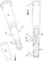
Fig. 1 is a perspective view of a rigid needle shield mounted on a syringe and a first alternative of a cover according to the application, -
Fig. 2 is a cross-sectional view of the needle shield assembly ofFig. 1 , -
Fig. 3 is a cross-sectional view of the needle shield assembly connected with a protective cap of a medicament delivery device, -
Figs. 4 and 5 are cross-sectional view of a second alternative of a cover according to the application, -
Figs. 6 and 7 are cross-sectional views of a modification of the alternative ofFigs. 4 and 5 , -
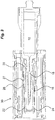
Fig. 8 is a cross-sectional view of a third alternative of a cover according to the application, -
Fig. 9 is a perspective view of an end area of the third alternative ofFig. 8 , -
Fig. 10 is a modified outer shield for a needle shield assembly, and -
Fig. 11 is a perspective view of the third alternative integrated with a protective cap of a medicament delivery device. -
Figure 1 shows asyringe 10 having astopper 12 and being provided with a conventional rigid needle shield orRNS 14. TheRNS 14 has aninner shield 16 of softer flexible material capable of surrounding and protecting aninjection needle 18 of thesyringe 10. The material of theinner shield 16 may be rubber, thermoplastic elastomers or other having the same type of material properties. The material of theinner shield 16 is permeable by gases such as sterilizing gases that are used to sterilize in particular the interior passage of theinjection needle 18. The sterilizing gases may for example comprise ethylene oxide or steam. Outside theinner shield 16, an outerrigid shield 20 is placed coaxially. Theouter shield 20 comprises a material that is much harder than the inner shield such as polypropylene, which also is impermeable to sterilizing gases. In order to allow sterilization, with the outer and inner shields mounted onto an injection needle, theouter shield 20 is arranged withpassages 22, such as slits as shown inFig. 1 . - According to the present application, the aim is to prolong the shelf life of the syringe and to minimize the penetration of surrounding oxygen into in particular the passage of the injection needle, thereby preventing exposure of the medicament to oxygen, which would degrade the medicament. This may be done according to one solution shown in
Figs. 1 and 2 , wherein thepassages 22 in the outer shield are covered by a suitable closure. In the embodiment shown inFig. 1 and 2 , the closure is in the form of anelongated tube 24 closed in a proximal end thereof. Thetube 24 may have a diameter that corresponds to the outer diameter of theouter shield 20 such that a press fit is obtained when thetube 24 is pressed onto theouter shield 20. As an alternative or in addition, the distal end of thetube 24 may be provided with an annular inwardly directedledge 26 that will provide a firm contact with the outer surface of theouter shield 20. Further, in order to provide a support for pulling the whole unit with the RNS and the closure off theinjection needle 18 when thesyringe 10 is to be used for delivering a dose, the distal end of thetube 24 may be arranged with an outwardly directedportion 27, in the embodiment shown outwardly inclined. This portion may then fit into arecess 28 in aprotective cap 30 that is removed when a dose is to be administered, as seen inFig. 3 . -
Figures 4 and 5 show a variant of protecting the inner passage and thus the medicament from oxygen after sterilization. In this case aninner shield 32 is arranged with a generallytubular passage 34 in its proximal end in which the tip of theinjection needle 18 fits when the RNS is put onto theinjection needle 18. Inside the tubular passage aneedle tip cover 36 is arranged movable, whichneedle tip cover 36 is made of a material impermeable to oxygen. Further the proximal end surface of an outer shield 38 is arranged with acentral passage 40, whereby thetubular passage 34 of theinner shield 32 is accessible. When an injection needle is to be sterilized, theneedle tip cover 36 is in a proximal position as seen inFig. 4 whereby theinjection needle 18 can be completely exposed to sterilization gases. After sterilization, a suitable tool is inserted through thecentral passage 40 of the outer shield 38 and theneedle tip cover 36 is pushed onto the tip of theinjection needle 18, whereby the passage in the injection needle is closed. In this regard, theneedle tip cover 34 may be of a flexible material allowing penetration by the injection needle. Alternatively or in addition, theneedle tip cover 34 may have a closed recess or passage having a diameter somewhat smaller than the outer diameter of theinjection needle 18, into which recess the tip may fit. - A variant to the embodiment of
Figs. 4 and 5 is shown inFigs. 6 and 7 . Here theinner passage 34 is arranged with a first inwardly directed rathersmall ledge 42 that will prevent he needle tip cover 36 from moving in thepassage 34 until theneedle tip cover 36 is pushed passed thefirst ledge 42 by an appropriate tool. By this it is prevented that theneedle tip cover 36 is unintentionally blocking the tip of theinjection needle 18 during the sterilization sequence. When the sterilization sequence has been performed theneedle tip cover 36 is pushed past thefirst ledge 42 and onto the tip of theinjection needle 18,Fig. 7 . With this variant asecond ledge 44 may be arranged that preferably is larger than thefirst ledge 42, where thesecond ledge 44 functions as a stop surface for theneedle tip cover 36, ascertaining that theneedle tip cover 36 cannot be pushed too far onto the needle tip. - A further alternative is shown in
figures 8 to 11 . Here a closure is arranged that is designed as acap 46,Figs. 8 and 9 , that encloses a major part of the outer surface of theouter shield 20 of the RNS. Thecap 46 may be pushed onto theouter shield 20 of the RNS after sterilization. Preferably the RNS is supported in the distal end when thecap 46 is pushed onto the RNS. Thecap 46 may further preferably be arranged withgripping elements 48 that are capable of providing a grip on the surface of theouter shield 20 in order to be able to remove the RNS when the syringe is to be used. In one example the gripping elements may comprise wedge-shaped inwardly directedledges 48 as seen inFigs. 7 and8 . Alternatively the wedge-shapedledges 48 and the length of the cap may be designed such that theledges 48 are placed behind the distal end surface of theouter shield 20 when the cap is mounted onto the RNS. In order to facilitate the assembly of the outer cap with the cap, a number oflongitudinal slits 50 may be provided around the distal end area of thecap 46, forming a number of distally directedtongues 52 that tare flexible in the generally radial direction, wherein theledges 48 are positioned on the inner surfaces of thetongues 52. With this solution, theledges 48 may flex out radially during the mounting of thecap 46 onto the RNS, wherein thetongues 52 may flex back inwards after theledges 48 have passed the distal end of theouter shield 20 of the RNS. As an alternative, theouter shield 20 may be specially designed to accommodate ledges of the outer cap,Fig. 10 , forexample having recesses 54 or ledges that cooperate with theledges 48 of thecap 46. Further, in order to obtain a rotational lock between theouter shield 20 and the cap, support surfaces may be arranged. In the embodiment shown, the outer surface of theouter cap 20 is arranged with proximally directedsurfaces 58 that are inclined in relation to the longitudinal axis of the outer shield. Thesesurfaces 58 are designed and arranged to cooperate with distally directedsurfaces 60 that also are inclined such that when the outer shield is connected to the cap, theinclined surfaces - According to a development of the last embodiment, the
cap 46 may be an integral part of asafety cap 62 as seen inFig. 11 . With this solution, fewer components are needed for obtaining the same function. - It is to be understood that the embodiments described above and shown in the drawings are to be regarded only as non-limiting examples and that the needle shield assembly may be modified in many ways within the scope of the patent claims.
Claims (15)
- A needle shield assembly for a syringe (10), comprising- an inner needle shield (16) which is flexible and designed to enclose a major part of a hollow injection needle (18) of said syringe;- an outer needle shield (20) which is rigid and designed to enclose a major part of said inner needle shield (16), which outer needle shield (20) is arranged with a number of passages (22) for allowing sterilizing agents to reach said injection needle (18) during a sterilization process;characterised in that said needle shield assembly further comprises a cover element (24; 36; 46) arranged adjacent said passages (22) such as to prevent the interior of said injection needle (18) from being exposed to oxygen via said passages (22) of said outer needle shield (20) after said sterilization process.
- The needle shield assembly of claim 1, wherein said cover element (24; 36; 46) is made of an oxygen-impermeable material.
- The needle shield assembly of claim 1, wherein said cover element comprises a sleeve (36; 42) arranged to be attached to and cover at least a part of the outer needle shield (20) that comprises the passages (22).
- The needle shield assembly of claim 3, wherein said sleeve (36; 42) comprises gripping elements (24, 26; 46, 48) capable of engaging an outer surface of the rigid needle shield.
- The needle shield assembly of claim 4, wherein the gripping elements (24; 46) comprise mainly friction enhancing elements, enhancing the friction between said sleeve and said outer needle shield.
- The needle shield assembly of claim 4, wherein the gripping elements (26; 48) comprise positive connecting elements.
- The needle shield assembly of claim 2, wherein said cover element comprises a needle tip cover (36) arranged to be movable inside said inner needle shield (16) from a first position proximal of said injection needle to a second position enclosing at least a proximal part of said injection needle (18).
- The needle shield assembly of claim 7, wherein said needle tip cover (36) is of a material allowing said injection needle (18) to be imbedded therein.
- The needle shield assembly of claim 7 or 8, wherein said inner needle shield further comprises an annular inwardly directed support element (44), and wherein said needle tip cover (36) is moved into contact with said support element (44) when moved to the second position.
- The needle shield assembly of any of claims 7 to 9, wherein said outer needle shield (20) is arranged with a proximally directed passage (40), through which passage (40) said needle tip cover (36) is accessible for movement from said first position to said second position.
- The needle shield assembly of any of the claims 3 to 10, further comprising connecting elements (27), designed for connection with a cap (30) of a medicament delivery device.
- The needle shield assembly of claim 11, wherein the connecting elements comprise mainly friction enhancing elements, enhancing the friction between said cap and said sleeve.
- The needle shield assembly of claim 11, wherein the connecting elements comprise positive connecting elements.
- The needle shield assembly according to any of the preceding claims, wherein said cover element (46) is an integral part of a cap (62) of a medicament delivery device.
- A medicament delivery device comprising a needle shield assembly according to any of the claims 1 to 14.
Priority Applications (2)
| Application Number | Priority Date | Filing Date | Title |
|---|---|---|---|
| EP17195204.7A EP3466467B1 (en) | 2017-10-06 | 2017-10-06 | Needle shield assembly |
| US16/150,395 US11045609B2 (en) | 2017-10-06 | 2018-10-03 | Protective assembly for a syringe |
Applications Claiming Priority (1)
| Application Number | Priority Date | Filing Date | Title |
|---|---|---|---|
| EP17195204.7A EP3466467B1 (en) | 2017-10-06 | 2017-10-06 | Needle shield assembly |
Publications (2)
| Publication Number | Publication Date |
|---|---|
| EP3466467A1 true EP3466467A1 (en) | 2019-04-10 |
| EP3466467B1 EP3466467B1 (en) | 2022-04-27 |
Family
ID=60037471
Family Applications (1)
| Application Number | Title | Priority Date | Filing Date |
|---|---|---|---|
| EP17195204.7A Active EP3466467B1 (en) | 2017-10-06 | 2017-10-06 | Needle shield assembly |
Country Status (2)
| Country | Link |
|---|---|
| US (1) | US11045609B2 (en) |
| EP (1) | EP3466467B1 (en) |
Citations (6)
| Publication number | Priority date | Publication date | Assignee | Title |
|---|---|---|---|---|
| US2700386A (en) * | 1953-05-07 | 1955-01-25 | Robert W Ogle | Syringe |
| US2860635A (en) * | 1957-03-20 | 1958-11-18 | Edgar H Wilburn | Sterilizable and sterilized hypodermic syringe assemblies |
| GB920341A (en) * | 1960-03-09 | 1963-03-06 | Roy Acton Glasson | Surgical needles |
| FR2777787A1 (en) * | 1998-04-22 | 1999-10-29 | Stelmi Trading International | Syringe needle guard comprising rigid outer shell over-molded onto supple liner with axial cavity for needle holder |
| US20050027259A1 (en) * | 2003-04-09 | 2005-02-03 | Arzneimittel Gmbh Apotheker Vetter & Co. Ravensburg | Prefilled hypodermic syringe |
| US20140364805A1 (en) * | 2007-09-25 | 2014-12-11 | Becton Dickinson France S.A.S | Injector with deshielder |
Family Cites Families (2)
| Publication number | Priority date | Publication date | Assignee | Title |
|---|---|---|---|---|
| FR2816848B1 (en) * | 2000-11-17 | 2003-06-20 | Rumpler Technologies | PROTECTION DEVICE FOR SYRINGE NEEDLE |
| CN107106777B (en) * | 2014-12-22 | 2020-10-02 | 诺和诺德股份有限公司 | Injection device with removable cap |
-
2017
- 2017-10-06 EP EP17195204.7A patent/EP3466467B1/en active Active
-
2018
- 2018-10-03 US US16/150,395 patent/US11045609B2/en active Active
Patent Citations (6)
| Publication number | Priority date | Publication date | Assignee | Title |
|---|---|---|---|---|
| US2700386A (en) * | 1953-05-07 | 1955-01-25 | Robert W Ogle | Syringe |
| US2860635A (en) * | 1957-03-20 | 1958-11-18 | Edgar H Wilburn | Sterilizable and sterilized hypodermic syringe assemblies |
| GB920341A (en) * | 1960-03-09 | 1963-03-06 | Roy Acton Glasson | Surgical needles |
| FR2777787A1 (en) * | 1998-04-22 | 1999-10-29 | Stelmi Trading International | Syringe needle guard comprising rigid outer shell over-molded onto supple liner with axial cavity for needle holder |
| US20050027259A1 (en) * | 2003-04-09 | 2005-02-03 | Arzneimittel Gmbh Apotheker Vetter & Co. Ravensburg | Prefilled hypodermic syringe |
| US20140364805A1 (en) * | 2007-09-25 | 2014-12-11 | Becton Dickinson France S.A.S | Injector with deshielder |
Also Published As
| Publication number | Publication date |
|---|---|
| US20190105446A1 (en) | 2019-04-11 |
| US11045609B2 (en) | 2021-06-29 |
| EP3466467B1 (en) | 2022-04-27 |
Similar Documents
| Publication | Publication Date | Title |
|---|---|---|
| DK2919834T3 (en) | INJECTION NEEDLE UNIT | |
| JP5563075B2 (en) | Drug container holder configuration | |
| TWI543789B (en) | Device for removing delivery member shields | |
| JP3553949B2 (en) | Implant injection device | |
| US6648858B2 (en) | Safety device for a sheathed, prefilled injection syringe | |
| US20140224688A1 (en) | Package for a medicament delivery device | |
| JP6105288B2 (en) | Pen needle removal device for drug delivery device | |
| TWI605846B (en) | Medicament delivery device | |
| JP2009523039A (en) | Safety needle | |
| JP2018502670A (en) | Device for protecting a needle, syringe equipped with such a device, and method for making a pre-filled cemented needle syringe | |
| JP2016526996A (en) | Needle shield removal device (remover) | |
| JP6125513B2 (en) | Needle safety device | |
| JP4961355B2 (en) | A passively protected and filled syringe | |
| CN105960255A (en) | Injection needle covering system | |
| JP2018518317A (en) | Syringe with joined needle | |
| WO2016158627A1 (en) | Assembly for protecting puncture needle, syringe assembly, and method for manufacturing same | |
| US11878155B2 (en) | Passive integrated safety device and an injection device comprising this passive integrated safety device | |
| JP2020509883A (en) | Needle protection device for prefilled syringe with staked needle, and syringe with such device | |
| DK2734257T3 (en) | Needle protection devices | |
| EP3466467B1 (en) | Needle shield assembly | |
| US11318259B2 (en) | Needle shield remover | |
| CN113727748B (en) | Needle cap with undercut | |
| US11052201B2 (en) | Protective cover for a dental syringe needle | |
| JP2022535670A (en) | pen needle magazine | |
| US11857772B2 (en) | Needle shield remover |
Legal Events
| Date | Code | Title | Description |
|---|---|---|---|
| PUAI | Public reference made under article 153(3) epc to a published international application that has entered the european phase |
Free format text: ORIGINAL CODE: 0009012 |
|
| STAA | Information on the status of an ep patent application or granted ep patent |
Free format text: STATUS: THE APPLICATION HAS BEEN PUBLISHED |
|
| AK | Designated contracting states |
Kind code of ref document: A1 Designated state(s): AL AT BE BG CH CY CZ DE DK EE ES FI FR GB GR HR HU IE IS IT LI LT LU LV MC MK MT NL NO PL PT RO RS SE SI SK SM TR |
|
| AX | Request for extension of the european patent |
Extension state: BA ME |
|
| STAA | Information on the status of an ep patent application or granted ep patent |
Free format text: STATUS: REQUEST FOR EXAMINATION WAS MADE |
|
| 17P | Request for examination filed |
Effective date: 20190917 |
|
| RBV | Designated contracting states (corrected) |
Designated state(s): AL AT BE BG CH CY CZ DE DK EE ES FI FR GB GR HR HU IE IS IT LI LT LU LV MC MK MT NL NO PL PT RO RS SE SI SK SM TR |
|
| STAA | Information on the status of an ep patent application or granted ep patent |
Free format text: STATUS: EXAMINATION IS IN PROGRESS |
|
| 17Q | First examination report despatched |
Effective date: 20200619 |
|
| GRAP | Despatch of communication of intention to grant a patent |
Free format text: ORIGINAL CODE: EPIDOSNIGR1 |
|
| STAA | Information on the status of an ep patent application or granted ep patent |
Free format text: STATUS: GRANT OF PATENT IS INTENDED |
|
| INTG | Intention to grant announced |
Effective date: 20211209 |
|
| GRAS | Grant fee paid |
Free format text: ORIGINAL CODE: EPIDOSNIGR3 |
|
| GRAA | (expected) grant |
Free format text: ORIGINAL CODE: 0009210 |
|
| STAA | Information on the status of an ep patent application or granted ep patent |
Free format text: STATUS: THE PATENT HAS BEEN GRANTED |
|
| AK | Designated contracting states |
Kind code of ref document: B1 Designated state(s): AL AT BE BG CH CY CZ DE DK EE ES FI FR GB GR HR HU IE IS IT LI LT LU LV MC MK MT NL NO PL PT RO RS SE SI SK SM TR |
|
| REG | Reference to a national code |
Ref country code: GB Ref legal event code: FG4D |
|
| REG | Reference to a national code |
Ref country code: CH Ref legal event code: EP |
|
| REG | Reference to a national code |
Ref country code: DE Ref legal event code: R096 Ref document number: 602017056478 Country of ref document: DE |
|
| REG | Reference to a national code |
Ref country code: AT Ref legal event code: REF Ref document number: 1486438 Country of ref document: AT Kind code of ref document: T Effective date: 20220515 |
|
| REG | Reference to a national code |
Ref country code: IE Ref legal event code: FG4D |
|
| REG | Reference to a national code |
Ref country code: LT Ref legal event code: MG9D |
|
| REG | Reference to a national code |
Ref country code: NL Ref legal event code: MP Effective date: 20220427 |
|
| REG | Reference to a national code |
Ref country code: AT Ref legal event code: MK05 Ref document number: 1486438 Country of ref document: AT Kind code of ref document: T Effective date: 20220427 |
|
| PG25 | Lapsed in a contracting state [announced via postgrant information from national office to epo] |
Ref country code: NL Free format text: LAPSE BECAUSE OF FAILURE TO SUBMIT A TRANSLATION OF THE DESCRIPTION OR TO PAY THE FEE WITHIN THE PRESCRIBED TIME-LIMIT Effective date: 20220427 |
|
| PG25 | Lapsed in a contracting state [announced via postgrant information from national office to epo] |
Ref country code: SE Free format text: LAPSE BECAUSE OF FAILURE TO SUBMIT A TRANSLATION OF THE DESCRIPTION OR TO PAY THE FEE WITHIN THE PRESCRIBED TIME-LIMIT Effective date: 20220427 Ref country code: PT Free format text: LAPSE BECAUSE OF FAILURE TO SUBMIT A TRANSLATION OF THE DESCRIPTION OR TO PAY THE FEE WITHIN THE PRESCRIBED TIME-LIMIT Effective date: 20220829 Ref country code: NO Free format text: LAPSE BECAUSE OF FAILURE TO SUBMIT A TRANSLATION OF THE DESCRIPTION OR TO PAY THE FEE WITHIN THE PRESCRIBED TIME-LIMIT Effective date: 20220727 Ref country code: LT Free format text: LAPSE BECAUSE OF FAILURE TO SUBMIT A TRANSLATION OF THE DESCRIPTION OR TO PAY THE FEE WITHIN THE PRESCRIBED TIME-LIMIT Effective date: 20220427 Ref country code: HR Free format text: LAPSE BECAUSE OF FAILURE TO SUBMIT A TRANSLATION OF THE DESCRIPTION OR TO PAY THE FEE WITHIN THE PRESCRIBED TIME-LIMIT Effective date: 20220427 Ref country code: GR Free format text: LAPSE BECAUSE OF FAILURE TO SUBMIT A TRANSLATION OF THE DESCRIPTION OR TO PAY THE FEE WITHIN THE PRESCRIBED TIME-LIMIT Effective date: 20220728 Ref country code: FI Free format text: LAPSE BECAUSE OF FAILURE TO SUBMIT A TRANSLATION OF THE DESCRIPTION OR TO PAY THE FEE WITHIN THE PRESCRIBED TIME-LIMIT Effective date: 20220427 Ref country code: ES Free format text: LAPSE BECAUSE OF FAILURE TO SUBMIT A TRANSLATION OF THE DESCRIPTION OR TO PAY THE FEE WITHIN THE PRESCRIBED TIME-LIMIT Effective date: 20220427 Ref country code: BG Free format text: LAPSE BECAUSE OF FAILURE TO SUBMIT A TRANSLATION OF THE DESCRIPTION OR TO PAY THE FEE WITHIN THE PRESCRIBED TIME-LIMIT Effective date: 20220727 Ref country code: AT Free format text: LAPSE BECAUSE OF FAILURE TO SUBMIT A TRANSLATION OF THE DESCRIPTION OR TO PAY THE FEE WITHIN THE PRESCRIBED TIME-LIMIT Effective date: 20220427 |
|
| PG25 | Lapsed in a contracting state [announced via postgrant information from national office to epo] |
Ref country code: RS Free format text: LAPSE BECAUSE OF FAILURE TO SUBMIT A TRANSLATION OF THE DESCRIPTION OR TO PAY THE FEE WITHIN THE PRESCRIBED TIME-LIMIT Effective date: 20220427 Ref country code: PL Free format text: LAPSE BECAUSE OF FAILURE TO SUBMIT A TRANSLATION OF THE DESCRIPTION OR TO PAY THE FEE WITHIN THE PRESCRIBED TIME-LIMIT Effective date: 20220427 Ref country code: LV Free format text: LAPSE BECAUSE OF FAILURE TO SUBMIT A TRANSLATION OF THE DESCRIPTION OR TO PAY THE FEE WITHIN THE PRESCRIBED TIME-LIMIT Effective date: 20220427 Ref country code: IS Free format text: LAPSE BECAUSE OF FAILURE TO SUBMIT A TRANSLATION OF THE DESCRIPTION OR TO PAY THE FEE WITHIN THE PRESCRIBED TIME-LIMIT Effective date: 20220827 |
|
| REG | Reference to a national code |
Ref country code: DE Ref legal event code: R097 Ref document number: 602017056478 Country of ref document: DE |
|
| PG25 | Lapsed in a contracting state [announced via postgrant information from national office to epo] |
Ref country code: SM Free format text: LAPSE BECAUSE OF FAILURE TO SUBMIT A TRANSLATION OF THE DESCRIPTION OR TO PAY THE FEE WITHIN THE PRESCRIBED TIME-LIMIT Effective date: 20220427 Ref country code: SK Free format text: LAPSE BECAUSE OF FAILURE TO SUBMIT A TRANSLATION OF THE DESCRIPTION OR TO PAY THE FEE WITHIN THE PRESCRIBED TIME-LIMIT Effective date: 20220427 Ref country code: RO Free format text: LAPSE BECAUSE OF FAILURE TO SUBMIT A TRANSLATION OF THE DESCRIPTION OR TO PAY THE FEE WITHIN THE PRESCRIBED TIME-LIMIT Effective date: 20220427 Ref country code: EE Free format text: LAPSE BECAUSE OF FAILURE TO SUBMIT A TRANSLATION OF THE DESCRIPTION OR TO PAY THE FEE WITHIN THE PRESCRIBED TIME-LIMIT Effective date: 20220427 Ref country code: DK Free format text: LAPSE BECAUSE OF FAILURE TO SUBMIT A TRANSLATION OF THE DESCRIPTION OR TO PAY THE FEE WITHIN THE PRESCRIBED TIME-LIMIT Effective date: 20220427 Ref country code: CZ Free format text: LAPSE BECAUSE OF FAILURE TO SUBMIT A TRANSLATION OF THE DESCRIPTION OR TO PAY THE FEE WITHIN THE PRESCRIBED TIME-LIMIT Effective date: 20220427 |
|
| PLBE | No opposition filed within time limit |
Free format text: ORIGINAL CODE: 0009261 |
|
| STAA | Information on the status of an ep patent application or granted ep patent |
Free format text: STATUS: NO OPPOSITION FILED WITHIN TIME LIMIT |
|
| PG25 | Lapsed in a contracting state [announced via postgrant information from national office to epo] |
Ref country code: AL Free format text: LAPSE BECAUSE OF FAILURE TO SUBMIT A TRANSLATION OF THE DESCRIPTION OR TO PAY THE FEE WITHIN THE PRESCRIBED TIME-LIMIT Effective date: 20220427 |
|
| 26N | No opposition filed |
Effective date: 20230130 |
|
| PG25 | Lapsed in a contracting state [announced via postgrant information from national office to epo] |
Ref country code: SI Free format text: LAPSE BECAUSE OF FAILURE TO SUBMIT A TRANSLATION OF THE DESCRIPTION OR TO PAY THE FEE WITHIN THE PRESCRIBED TIME-LIMIT Effective date: 20220427 Ref country code: MC Free format text: LAPSE BECAUSE OF FAILURE TO SUBMIT A TRANSLATION OF THE DESCRIPTION OR TO PAY THE FEE WITHIN THE PRESCRIBED TIME-LIMIT Effective date: 20220427 |
|
| P01 | Opt-out of the competence of the unified patent court (upc) registered |
Effective date: 20230425 |
|
| REG | Reference to a national code |
Ref country code: BE Ref legal event code: MM Effective date: 20221031 |
|
| PG25 | Lapsed in a contracting state [announced via postgrant information from national office to epo] |
Ref country code: LU Free format text: LAPSE BECAUSE OF NON-PAYMENT OF DUE FEES Effective date: 20221006 |
|
| PG25 | Lapsed in a contracting state [announced via postgrant information from national office to epo] |
Ref country code: BE Free format text: LAPSE BECAUSE OF NON-PAYMENT OF DUE FEES Effective date: 20221031 |
|
| PG25 | Lapsed in a contracting state [announced via postgrant information from national office to epo] |
Ref country code: IE Free format text: LAPSE BECAUSE OF NON-PAYMENT OF DUE FEES Effective date: 20221006 |
|
| PG25 | Lapsed in a contracting state [announced via postgrant information from national office to epo] |
Ref country code: IT Free format text: LAPSE BECAUSE OF FAILURE TO SUBMIT A TRANSLATION OF THE DESCRIPTION OR TO PAY THE FEE WITHIN THE PRESCRIBED TIME-LIMIT Effective date: 20220427 |
|
| PG25 | Lapsed in a contracting state [announced via postgrant information from national office to epo] |
Ref country code: HU Free format text: LAPSE BECAUSE OF FAILURE TO SUBMIT A TRANSLATION OF THE DESCRIPTION OR TO PAY THE FEE WITHIN THE PRESCRIBED TIME-LIMIT; INVALID AB INITIO Effective date: 20171006 |
|
| PG25 | Lapsed in a contracting state [announced via postgrant information from national office to epo] |
Ref country code: CY Free format text: LAPSE BECAUSE OF FAILURE TO SUBMIT A TRANSLATION OF THE DESCRIPTION OR TO PAY THE FEE WITHIN THE PRESCRIBED TIME-LIMIT Effective date: 20220427 |
|
| PG25 | Lapsed in a contracting state [announced via postgrant information from national office to epo] |
Ref country code: MK Free format text: LAPSE BECAUSE OF FAILURE TO SUBMIT A TRANSLATION OF THE DESCRIPTION OR TO PAY THE FEE WITHIN THE PRESCRIBED TIME-LIMIT Effective date: 20220427 |
|
| PG25 | Lapsed in a contracting state [announced via postgrant information from national office to epo] |
Ref country code: TR Free format text: LAPSE BECAUSE OF FAILURE TO SUBMIT A TRANSLATION OF THE DESCRIPTION OR TO PAY THE FEE WITHIN THE PRESCRIBED TIME-LIMIT Effective date: 20220427 |
|
| PG25 | Lapsed in a contracting state [announced via postgrant information from national office to epo] |
Ref country code: MT Free format text: LAPSE BECAUSE OF FAILURE TO SUBMIT A TRANSLATION OF THE DESCRIPTION OR TO PAY THE FEE WITHIN THE PRESCRIBED TIME-LIMIT Effective date: 20220427 |
|
| PGFP | Annual fee paid to national office [announced via postgrant information from national office to epo] |
Ref country code: GB Payment date: 20240906 Year of fee payment: 8 |
|
| PGFP | Annual fee paid to national office [announced via postgrant information from national office to epo] |
Ref country code: FR Payment date: 20240923 Year of fee payment: 8 |
|
| PG25 | Lapsed in a contracting state [announced via postgrant information from national office to epo] |
Ref country code: BG Free format text: LAPSE BECAUSE OF FAILURE TO SUBMIT A TRANSLATION OF THE DESCRIPTION OR TO PAY THE FEE WITHIN THE PRESCRIBED TIME-LIMIT Effective date: 20220427 |
|
| PG25 | Lapsed in a contracting state [announced via postgrant information from national office to epo] |
Ref country code: BG Free format text: LAPSE BECAUSE OF FAILURE TO SUBMIT A TRANSLATION OF THE DESCRIPTION OR TO PAY THE FEE WITHIN THE PRESCRIBED TIME-LIMIT Effective date: 20220427 |
|
| PGFP | Annual fee paid to national office [announced via postgrant information from national office to epo] |
Ref country code: DE Payment date: 20240904 Year of fee payment: 8 |
|
| PGFP | Annual fee paid to national office [announced via postgrant information from national office to epo] |
Ref country code: CH Payment date: 20241101 Year of fee payment: 8 |