EP3466333A1 - Biomagnetism measuring device - Google Patents
Biomagnetism measuring device Download PDFInfo
- Publication number
- EP3466333A1 EP3466333A1 EP17806823.5A EP17806823A EP3466333A1 EP 3466333 A1 EP3466333 A1 EP 3466333A1 EP 17806823 A EP17806823 A EP 17806823A EP 3466333 A1 EP3466333 A1 EP 3466333A1
- Authority
- EP
- European Patent Office
- Prior art keywords
- magnetic sensors
- measuring device
- biomagnetism measuring
- sensors
- biomagnetism
- Prior art date
- Legal status (The legal status is an assumption and is not a legal conclusion. Google has not performed a legal analysis and makes no representation as to the accuracy of the status listed.)
- Ceased
Links
Images



Classifications
-
- A—HUMAN NECESSITIES
- A61—MEDICAL OR VETERINARY SCIENCE; HYGIENE
- A61B—DIAGNOSIS; SURGERY; IDENTIFICATION
- A61B5/00—Measuring for diagnostic purposes; Identification of persons
- A61B5/05—Detecting, measuring or recording for diagnosis by means of electric currents or magnetic fields; Measuring using microwaves or radio waves
-
- G—PHYSICS
- G01—MEASURING; TESTING
- G01R—MEASURING ELECTRIC VARIABLES; MEASURING MAGNETIC VARIABLES
- G01R33/00—Arrangements or instruments for measuring magnetic variables
-
- G—PHYSICS
- G01—MEASURING; TESTING
- G01R—MEASURING ELECTRIC VARIABLES; MEASURING MAGNETIC VARIABLES
- G01R33/00—Arrangements or instruments for measuring magnetic variables
- G01R33/0094—Sensor arrays
-
- A—HUMAN NECESSITIES
- A61—MEDICAL OR VETERINARY SCIENCE; HYGIENE
- A61B—DIAGNOSIS; SURGERY; IDENTIFICATION
- A61B2562/00—Details of sensors; Constructional details of sensor housings or probes; Accessories for sensors
- A61B2562/02—Details of sensors specially adapted for in-vivo measurements
- A61B2562/0223—Magnetic field sensors
-
- A—HUMAN NECESSITIES
- A61—MEDICAL OR VETERINARY SCIENCE; HYGIENE
- A61B—DIAGNOSIS; SURGERY; IDENTIFICATION
- A61B2562/00—Details of sensors; Constructional details of sensor housings or probes; Accessories for sensors
- A61B2562/04—Arrangements of multiple sensors of the same type
- A61B2562/046—Arrangements of multiple sensors of the same type in a matrix array
-
- A—HUMAN NECESSITIES
- A61—MEDICAL OR VETERINARY SCIENCE; HYGIENE
- A61B—DIAGNOSIS; SURGERY; IDENTIFICATION
- A61B2562/00—Details of sensors; Constructional details of sensor housings or probes; Accessories for sensors
- A61B2562/16—Details of sensor housings or probes; Details of structural supports for sensors
-
- A—HUMAN NECESSITIES
- A61—MEDICAL OR VETERINARY SCIENCE; HYGIENE
- A61B—DIAGNOSIS; SURGERY; IDENTIFICATION
- A61B2576/00—Medical imaging apparatus involving image processing or analysis
- A61B2576/02—Medical imaging apparatus involving image processing or analysis specially adapted for a particular organ or body part
- A61B2576/023—Medical imaging apparatus involving image processing or analysis specially adapted for a particular organ or body part for the heart
-
- A—HUMAN NECESSITIES
- A61—MEDICAL OR VETERINARY SCIENCE; HYGIENE
- A61B—DIAGNOSIS; SURGERY; IDENTIFICATION
- A61B2576/00—Medical imaging apparatus involving image processing or analysis
- A61B2576/02—Medical imaging apparatus involving image processing or analysis specially adapted for a particular organ or body part
- A61B2576/026—Medical imaging apparatus involving image processing or analysis specially adapted for a particular organ or body part for the brain
-
- A—HUMAN NECESSITIES
- A61—MEDICAL OR VETERINARY SCIENCE; HYGIENE
- A61B—DIAGNOSIS; SURGERY; IDENTIFICATION
- A61B5/00—Measuring for diagnostic purposes; Identification of persons
- A61B5/40—Detecting, measuring or recording for evaluating the nervous system
- A61B5/4058—Detecting, measuring or recording for evaluating the nervous system for evaluating the central nervous system
- A61B5/4064—Evaluating the brain
Definitions
- the present invention relates to a biomagnetism measuring device that uses a magnetic sensor.
- MR magneto resistive
- MR element magneto resistive element
- MR sensors are widely used as magnetic heads in hard disc devices, rotation sensors (encoders) and position sensors. Further, in recent years, the widespread use of mobile devices such as smartphones and tablet devices has led to these mobile devices being provided with orientation sensors having MR sensors which use geomagnetism to measure orientation. The information obtained from the orientation sensor is used for navigation which uses location information obtained by a global positioning system (GPS).
- GPS global positioning system
- highly sensitive magnetic detection technology is not required for such industrial applications.
- highly sensitive magnetic detection is not required because magnets and the like are used as reference signals.
- orientation sensors do not require highly sensitive magnetic detection because it is enough to detect absolute azimuth with geomagnetism as a reference.
- biomagnetism measuring devices such as cerebral magnetometers, magneto cardiograms and muscular magnetometers which detect weak, low frequency magnetism generated by electrical activity in the brain, heart or muscles in a body have been used in recent years.
- Brain magnetism generated by electrical activity in the brain is approximately 1/100 million the strength of geomagnetism
- cardiomagnetism generated by electrical activity of the heart is approximately 1/1 million the strength of geomagnetism.
- biomagnetism the magnetic sensors used to detect magnetism generated by the body
- a SQUID sensor is a magnetic sensor that uses the phenomenon of superconductivity and has a Josephson junction. Because of this, SQUID sensors need to be cooled with a refrigerant such as liquid helium or liquid nitrogen during use. Therefore, SQUID sensors must be provided in a dewar that stores refrigerant, which makes it difficult for SQUID sensors to make close contact with a body for detection of biomagnetism.
- a plurality of the SQUID sensors are arranged in an array inside the dewar.
- the SQUID sensors must be arranged such that the Josephson junctions inside the SQUID sensors are not electromagnetically affected. Therefore, it is difficult to change the arrangement of SQUID sensors and replace or remove SQUID sensors.
- SQUID sensors have a problem in that, despite being high-precision magnetic sensors, they cannot be used close enough to the body and are difficult to handle.
- a biomagnetism measuring device which uses MR sensors that can detect slight magnetism at room temperature, thereby eliminating the need for cooling.
- Patent Document 2 there is proposed a biomagnetism measuring device in which a covering member which shields the body from an external magnetic field is formed into a helmet shape or a cylindrical shape, and MR sensors are provided inside the covering member in an array.
- the MR sensors may not be able to detect magnetism depending on the subject to be measured (body) because of reduced contact between the subject to be measured and the MR sensors.
- optimal MR sensor positions will be different for a subject to be measured that has a body shape different to that of a human, such as an animal.
- the resolution of required measurement results and optimal positions of the MR sensors will differ depending on the site to be measured.
- the inventors of the present invention carried out extensive research in order to solve the above-mentioned problem. As a result, the inventors found that it is possible to provide a biomagnetism measuring device with which magnetic sensors can be disposed at optimal positions according to the object to be measured by holding a plurality of magnetic sensors such that the magnetic sensors can be removed or moved. Thus, the inventors completed the present invention. More specifically, the present invention provides the following.
- a biomagnetism measuring device with which magnetic sensors can be disposed at optimal positions according to the object to be measured.
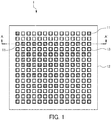
- FIG. 1 is a plan view for illustrating an example of a biomagnetism measuring device according to an embodiment of the present invention.
- FIG. 2 is a partially expanded view taken long the line A-A' in the biomagnetism measuring device in FIG. 1 .
- the biomagnetism measuring device 1 includes a plurality of magnetic sensors 11 configured to detect biomagnetism and a holding portion 12 which removably holds the magnetic sensors 11. Frames 13 which removably hold the magnetic sensors 11 are arranged in an array in the holding portion 12.
- the magnetic sensors 11 are configured to detect a magnetic field generated by a body to be measured (hereinafter referred to as "subject").
- a body to be measured hereinafter referred to as "subject”
- Examples of the type of sensor used as the magnetic sensor 11 include a giant magnetoresistance sensor (GMR sensor), a tunnel magneto resistance sensor (TMR sensor), an anisotropic magneto resistive sensor (AMR sensor), magnetic impedance sensor (MI sensor) and a fluxgate sensor.
- the magnetic sensor 11 used in this embodiment may be any kind of magnetic sensor provided that the magnetic sensor can detect a magnetic field (normal component) between about 10 -4 T (tesla) and 10 -10 T (tesla).
- the magnetic sensor 11 used in this embodiment can acquire the same amount of information as a SQUID sensor, can be used at room temperature and does not need to be disposed in a dewar that stores refrigerant. In addition, the magnetic sensors 11 can be brought closer to a body and are easier to handle than when SQUID sensors are used.
- the magnetic sensors 11 may or may not have wiring for receiving signals and power supply. However, because the plurality of magnetic sensors 11 are disposed in the biomagnetism measuring device 1, the biomagnetism measuring device 1 preferably includes wiring 15 as illustrated in FIG. 2 in order to prevent complex wiring.
- Signals detected by the magnetic sensors 11 are sent to a calculation unit (not shown).
- the calculation unit generates biomagnetic information from the signals detected by the magnetic sensors 11 and visualizes and outputs this information to a display device.
- the frames 13 are disposed in an array (14x14) in the holding portion 12.
- the frames 13 are configured to removably hold the magnetic sensors 11.
- a plurality of through holes 14 which accept insertion of the magnetic sensors 11 are formed in the holding portion 12, and the frames 13 which removably hold the magnetic sensors 11 are attached to openings which oppose the measurement subject of the through hole 14.
- the magnetic sensors 11 are not attached to the frames 13 using any particular mechanism and may be attached using a fixing tool such as a screw. With this configuration, the magnetic sensors 11 can be removed to the holding portion 12 and the frames 13 such that detection surfaces of the magnetic sensors 11 oppose a body.
- the above-described holding portion 12, frame 13 and fixing tools are preferably made of a plastic material such as an acrylic resin, a nonferrous metal such as copper or brass, or a nonmagnetic material such as wood.
- a plastic material such as an acrylic resin, a nonferrous metal such as copper or brass, or a nonmagnetic material such as wood.
- the person conducting the measurement determines the number of magnetic sensors 11 required and the positions of the magnetic sensors 11 according to the subject to be measured, for example, the stature of the subject or the site and attaches the predetermined magnetic sensors 11 at optimal positions on the frames 3 in the holding portion 2 of the biomagnetism measuring device 1. If the magnetic sensors 11 include the wiring 15 for receiving signals, the magnetic sensors 11 may be inserted into the through holes 14 from beneath the holding portion 12 and attached to the frames 13 using the fixing tools.
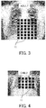
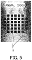
- the biomagnetism measuring device 1 For example, if using the biomagnetism measuring device 1 to obtain a magneto cardiogram and the subject is an adult, 42 magnetic sensors 11 should be attached to an array of 6x7 frames 13 (see FIG. 3 ) of the frames 13 arranged in a 14x14 array. If the subject is a child, 20 magnetic sensors 11 should be attached to an array of 5x4 frames 13 (see FIG. 4 ) of the frames 13 arranged in a 14x14 array. If the subject is a dog, 38 magnetic sensors 11 should be attached to an array of 5x1+7x4+5x1 frames 13 (see FIG. 5 ) of the frames 13 arranged in a 14x14 array.
- the positions of the frames 13 selected in order to attach the magnetic sensors 11 may be at a central portion or a peripheral portion of the holding portion 12 but are preferably at a central portion in consideration of improving stability of the subject.
- the resolution of required measurement results may differ.
- the magnetic sensors 11 may be concentrated at positions that require high resolution results and may be dispersed at positions that do not require high resolution results.
- the person conducting the measurement guides the subject so that the site to be measured is placed on the biomagnetism measuring device 1 disposed with the magnetic sensors 11 and checks if the detection surfaces of the magnetic sensors 11 are in close contact with the site to be measured. Then, the person conducting the measurement operates the biomagnetism measuring device 1 using an operation unit (not shown) and starts the measurement. Further, after guiding the subject so that the site to be measured is placed on the biomagnetism measuring device 1 disposed with the magnetic sensors 11, the person conducting the measurement may readjust the arrangement of the magnetic sensors 11 while confirming that the detection surfaces of the magnetic sensors 11 are in close contact with the site to be measured on the basis of the detection results of the magnetic sensors 11 by operating the biomagnetism measuring device 1.
- the magnetic sensors 11 are preferably disposed directly below the site to be measured. Therefore, for example, a subject 100 may lay face up on an examination table 2 embedded with the biomagnetism measuring device 1 (see FIG. 6 ). Alternatively, the subject 100 may lay face down on the examination table 2 (see FIG. 7 ). Through the subject 100 laying down on the examination table 2 embedded with the biomagnetism measuring device 1, gravity works on the subject 100 to improve contact between the body surface of the subject 100 and the detection surfaces of the magnetic sensors 11. As a result, the biomagnetism measuring device 1 can obtain more accurate biomagnetic information.
- biomagnetic information can be obtained in the optimal area.
- trouble such as biomagnetic information not being obtained due to lack of contact between the magnetic sensors 11 and the body is prevented.
- signal reception and power supply to unnecessary magnetic sensors 11 does not occur and power and costs can be saved.
- the number of magnetic sensors 11 required can be reduced. As a result, signal reception and power supply to unnecessary magnetic sensors 11 does not occur and power and costs can be saved.
- FIGS. 8 to 10 Modification examples of the biomagnetism measuring device according to this embodiment are described below with reference to FIGS. 8 to 10 . Note that in FIGS. 8 to 10 , components that are the same as above-described components are denoted by the same reference symbols and descriptions thereof are omitted.
- FIG. 8 illustrates a first modification example of the biomagnetism measuring device.
- the magnetic sensors 11 are removably held by the frames 13 in the holding portion 12, but the magnetic sensors 11 may be movably held by rails 16.
- a plurality of rails 16 which movably hold the magnetic sensors 11 are formed in parallel in the holding portion 12. With this configuration, the plurality of magnetic sensors 11 can be moved to arbitrary positions along the rails 16.
- the number of magnetic sensors 11 and rails 16 is not particularly limited and may be chosen as appropriate depending on the site to be measured.
- the magnetic sensors 11 may or may not be removable from the rails 16.
- the rails 16 are preferably made of a plastic material such as an acrylic resin, a nonferrous metal such as copper or brass, or a nonmagnetic material such as wood. Forming the holding portion 12 and the rails 16 of a nonmagnetic material can suppress fluctuation in environmental magnetism even if the holding portion 12 and the rails 16 vibrate due to the subject moving, for example, breathing. Therefore, the influence of fluctuation in environmental magnetism on the magnetic sensors 11 can be suppressed.
- a plastic material such as an acrylic resin, a nonferrous metal such as copper or brass, or a nonmagnetic material such as wood.
- the person conducting the measurement can easily move the magnetic sensors 11 along the rails 16 while checking measurement results when measuring biomagnetism of the subject.
- the biomagnetism measuring device 1' formed with the rails 16 in the holding portion 12 it is easy align the magnetic sensors 11 during measurement.
- FIG. 9 illustrates a second modification example of the biomagnetism measuring device.
- the above-described holding portion 12 is a molded body integrally molded with a nonmagnetic material such as plastic, a holding portion 17 may be made of a flexible material.
- the holding portion 17 illustrated in FIG. 9 includes a plurality of fixing portions 18 which individually fix the plurality of magnetic sensors 11 and hinges 19 which link the plurality of fixing portions 18 to each other.
- the hinges 19 By forming the hinges 19 of a flexible material such as rubber, the magnetic sensors 11 can be arranged on the holding portion 17 according to the shape of the body even if the body is uneven or curved, and the detection surfaces of the magnetic sensors 11 can make close contact with the body surface of the body.
- the biomagnetism measuring device including the holding portion 17 can accurately measure biomagnetism.
- the fixing portions 18 may also be made of a flexible material provided that the fixing portions 18 can fix the magnetic sensors 11.
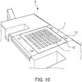
- FIG. 10 illustrates a third modification example of the biomagnetism measuring device.
- the biomagnetism measuring device 1 illustrated in FIGS. 6 and 7 is embedded into an examination table which the subject 100 lies on, the table into which the biomagnetism measuring device 1 is embedded is not limited thereto.
- the biomagnetism measuring device 1 may be embedded into a measurement table 3 which is smaller than the examination table 2.
- the measurement table 3 illustrated in FIG. 10 magnetism generated from the hand can be detected without the subject lying down on the table, and the magnetic sensors 11 can be attached at the optimal positions according to the size of the hand and the required resolution.
Landscapes
- Health & Medical Sciences (AREA)
- Life Sciences & Earth Sciences (AREA)
- Physics & Mathematics (AREA)
- Animal Behavior & Ethology (AREA)
- Medical Informatics (AREA)
- Veterinary Medicine (AREA)
- Public Health (AREA)
- Biophysics (AREA)
- Pathology (AREA)
- Engineering & Computer Science (AREA)
- Biomedical Technology (AREA)
- Heart & Thoracic Surgery (AREA)
- General Health & Medical Sciences (AREA)
- Molecular Biology (AREA)
- Surgery (AREA)
- Nuclear Medicine, Radiotherapy & Molecular Imaging (AREA)
- Radiology & Medical Imaging (AREA)
- Condensed Matter Physics & Semiconductors (AREA)
- General Physics & Mathematics (AREA)
- Measurement And Recording Of Electrical Phenomena And Electrical Characteristics Of The Living Body (AREA)
Abstract
Description
- The present invention relates to a biomagnetism measuring device that uses a magnetic sensor.
- As a magnetic sensor which detects magnetism, there is conventionally known a magneto resistive (MR) sensor which uses a magneto resistive element (MR element). DC resistance acting on the MR element fluctuates according to the strength of the magnetic field. The MR sensor uses the degree of fluctuation of DC resistance to detect magnetic field variance or the presence of magnetic material as a change in voltage.
- MR sensors are widely used as magnetic heads in hard disc devices, rotation sensors (encoders) and position sensors. Further, in recent years, the widespread use of mobile devices such as smartphones and tablet devices has led to these mobile devices being provided with orientation sensors having MR sensors which use geomagnetism to measure orientation. The information obtained from the orientation sensor is used for navigation which uses location information obtained by a global positioning system (GPS).
- However, highly sensitive magnetic detection technology is not required for such industrial applications. For example, in rotation sensors and position sensors, highly sensitive magnetic detection is not required because magnets and the like are used as reference signals. Further, orientation sensors do not require highly sensitive magnetic detection because it is enough to detect absolute azimuth with geomagnetism as a reference.
- Incidentally, for medical applications, biomagnetism measuring devices such as cerebral magnetometers, magneto cardiograms and muscular magnetometers which detect weak, low frequency magnetism generated by electrical activity in the brain, heart or muscles in a body have been used in recent years. Brain magnetism generated by electrical activity in the brain is approximately 1/100 million the strength of geomagnetism, and cardiomagnetism generated by electrical activity of the heart is approximately 1/1 million the strength of geomagnetism. Because of this, the magnetic sensors used to detect magnetism generated by the body (hereinafter also referred to as "biomagnetism") are required to have extremely precise detection ability.
- As a high-precision magnetic sensor which can is capable of highly precise magnetic detection, there is known a superconducting quantum interference device (hereinafter also referred to as "SQUID") (see, for example, Patent Document 1).
- A SQUID sensor is a magnetic sensor that uses the phenomenon of superconductivity and has a Josephson junction. Because of this, SQUID sensors need to be cooled with a refrigerant such as liquid helium or liquid nitrogen during use. Therefore, SQUID sensors must be provided in a dewar that stores refrigerant, which makes it difficult for SQUID sensors to make close contact with a body for detection of biomagnetism.
- Further, a plurality of the SQUID sensors are arranged in an array inside the dewar. However, the SQUID sensors must be arranged such that the Josephson junctions inside the SQUID sensors are not electromagnetically affected. Therefore, it is difficult to change the arrangement of SQUID sensors and replace or remove SQUID sensors.
- Therefore, SQUID sensors have a problem in that, despite being high-precision magnetic sensors, they cannot be used close enough to the body and are difficult to handle.
- In light of this, there has been proposed a biomagnetism measuring device which uses MR sensors that can detect slight magnetism at room temperature, thereby eliminating the need for cooling. For example, in
Patent Document 2, there is proposed a biomagnetism measuring device in which a covering member which shields the body from an external magnetic field is formed into a helmet shape or a cylindrical shape, and MR sensors are provided inside the covering member in an array. With this biomagnetism measuring device which uses MR sensors, there is no need to dispose the MR sensors in a dewar and the MR sensors are easier to handle and can be brought closer to the body compared to a device which uses SQUID sensors. -
- Patent Document 1: Japanese Unexamined Patent Application, Publication No.
2012-020143 - Patent Document 2: Japanese Unexamined Patent Application, Publication No.
2012-095939 - However, if the MR sensors are fixed in place as in the biomagnetism measuring device described in
Patent Document 2, the MR sensors may not be able to detect magnetism depending on the subject to be measured (body) because of reduced contact between the subject to be measured and the MR sensors. For example, optimal MR sensor positions will be different for a subject to be measured that has a body shape different to that of a human, such as an animal. In addition, the resolution of required measurement results and optimal positions of the MR sensors will differ depending on the site to be measured. - It is an object of the present invention to provide a biomagnetism measuring device with which magnetic sensors can be disposed at optimal positions according to the object to be measured.
- The inventors of the present invention carried out extensive research in order to solve the above-mentioned problem. As a result, the inventors found that it is possible to provide a biomagnetism measuring device with which magnetic sensors can be disposed at optimal positions according to the object to be measured by holding a plurality of magnetic sensors such that the magnetic sensors can be removed or moved. Thus, the inventors completed the present invention. More specifically, the present invention provides the following.
- (1) The present invention is a biomagnetism measuring device including a plurality of magnetic sensors configured to detect biomagnetism; and holding portions which removably or movably hold the plurality of magnetic sensors such that the plurality of magnetic sensors oppose a body.
- (2) The present invention is the biomagnetism measuring device of (1), in which frames are arranged in an array in the holding portion, the frames holding the plurality of magnetic sensors such that the plurality of magnetic sensors can be removed.
- (3) The present invention is the biomagnetism measuring device of (1), in which rails are arranged in an array in the holding portion, the rails holding the plurality of magnetic sensors such that the plurality of magnetic sensors can be slidably moved.
- (4) The present invention is the biomagnetism measuring device of any of (1) to (3), in which the holding portion is made of a nonmagnetic material.
- (5) The present invention is the biomagnetism measuring device of any of (1) to (4), in which the holding portion is made of a flexible material.
- (6) The present invention is the biomagnetism measuring device of any of (1) to (5), in which the magnetic sensors are disposed directly below a site to be measured.
- According to the present invention, there can be provided a biomagnetism measuring device with which magnetic sensors can be disposed at optimal positions according to the object to be measured.
-
-
FIG. 1 is a plan view for illustrating an exemplary configuration of a biomagnetism measuring device according to an embodiment of the present invention. -
FIG. 2 is a partially expanded view taken long the line A-A' in the biomagnetism measuring device inFIG. 1 . -
FIG. 3 is an explanatory diagram which shows an X-ray image of an adult subject overlaid with an arrangement diagram of magnetic sensors. -
FIG. 4 is an explanatory diagram which shows an X-ray image of a child subject overlaid with an arrangement diagram of magnetic sensors. -
FIG. 5 is an explanatory diagram which shows an X-ray image of a dog subject overlaid with an arrangement diagram of magnetic sensors. -
FIG. 6 is an explanatory diagram for explaining a configuration in which the magnetic sensors are disposed directly below a subject. -
FIG. 7 is an explanatory diagram for explaining another configuration in which the magnetic sensors are disposed directly below a subject. -
FIG. 8 is a plan view for illustrating a first modification example of the biomagnetism measuring device, in which a holding portion is provided with a rail. -
FIG. 9 is a plan view for illustrating a second modification example of the biomagnetism measuring device, in which the holding portion is made of a flexible material. -
FIG. 10 is a perspective view for illustrating a third modification example of the biomagnetism measuring device in which a table provided with the biomagnetism measuring device has been replaced with that having another configuration. - An embodiment of the present invention is described in detail below, but the present invention is not limited to the following embodiment and may be changed as appropriate without departing from the object of the present invention.
-
FIG. 1 is a plan view for illustrating an example of a biomagnetism measuring device according to an embodiment of the present invention.FIG. 2 is a partially expanded view taken long the line A-A' in the biomagnetism measuring device inFIG. 1 . As illustrated inFIG. 1 , the biomagnetismmeasuring device 1 includes a plurality ofmagnetic sensors 11 configured to detect biomagnetism and aholding portion 12 which removably holds themagnetic sensors 11.Frames 13 which removably hold themagnetic sensors 11 are arranged in an array in theholding portion 12. - The
magnetic sensors 11 are configured to detect a magnetic field generated by a body to be measured (hereinafter referred to as "subject"). Examples of the type of sensor used as themagnetic sensor 11 include a giant magnetoresistance sensor (GMR sensor), a tunnel magneto resistance sensor (TMR sensor), an anisotropic magneto resistive sensor (AMR sensor), magnetic impedance sensor (MI sensor) and a fluxgate sensor. Themagnetic sensor 11 used in this embodiment may be any kind of magnetic sensor provided that the magnetic sensor can detect a magnetic field (normal component) between about 10-4 T (tesla) and 10-10 T (tesla). Themagnetic sensor 11 used in this embodiment can acquire the same amount of information as a SQUID sensor, can be used at room temperature and does not need to be disposed in a dewar that stores refrigerant. In addition, themagnetic sensors 11 can be brought closer to a body and are easier to handle than when SQUID sensors are used. - The
magnetic sensors 11 may or may not have wiring for receiving signals and power supply. However, because the plurality ofmagnetic sensors 11 are disposed in thebiomagnetism measuring device 1, thebiomagnetism measuring device 1 preferably includeswiring 15 as illustrated inFIG. 2 in order to prevent complex wiring. - Signals detected by the
magnetic sensors 11 are sent to a calculation unit (not shown). The calculation unit generates biomagnetic information from the signals detected by themagnetic sensors 11 and visualizes and outputs this information to a display device. - As illustrated in
FIG. 1 , theframes 13 are disposed in an array (14x14) in the holdingportion 12. Theframes 13 are configured to removably hold themagnetic sensors 11. As illustrated inFIG. 2 , a plurality of throughholes 14 which accept insertion of themagnetic sensors 11 are formed in the holdingportion 12, and theframes 13 which removably hold themagnetic sensors 11 are attached to openings which oppose the measurement subject of the throughhole 14. Themagnetic sensors 11 are not attached to theframes 13 using any particular mechanism and may be attached using a fixing tool such as a screw. With this configuration, themagnetic sensors 11 can be removed to the holdingportion 12 and theframes 13 such that detection surfaces of themagnetic sensors 11 oppose a body. - The above-described
holding portion 12,frame 13 and fixing tools (not shown) are preferably made of a plastic material such as an acrylic resin, a nonferrous metal such as copper or brass, or a nonmagnetic material such as wood. Forming the holdingportion 12, theframes 13 and the fixing tools of a nonmagnetic material can suppress fluctuation in environmental magnetism even if the holdingportion 12, theframes 13 and the fixing tools vibrate due to the subject moving, for example, breathing. Therefore, the influence of fluctuation in environmental magnetism on themagnetic sensors 11 can be suppressed. - The procedure of measuring biomagnetism using the
biomagnetism measuring device 1 with the above-described configuration is described with reference toFIGS. 3 to 7 . - First, the person conducting the measurement determines the number of
magnetic sensors 11 required and the positions of themagnetic sensors 11 according to the subject to be measured, for example, the stature of the subject or the site and attaches the predeterminedmagnetic sensors 11 at optimal positions on theframes 3 in the holdingportion 2 of thebiomagnetism measuring device 1. If themagnetic sensors 11 include thewiring 15 for receiving signals, themagnetic sensors 11 may be inserted into the throughholes 14 from beneath the holdingportion 12 and attached to theframes 13 using the fixing tools. - For example, if using the
biomagnetism measuring device 1 to obtain a magneto cardiogram and the subject is an adult, 42magnetic sensors 11 should be attached to an array of 6x7 frames 13 (seeFIG. 3 ) of theframes 13 arranged in a 14x14 array. If the subject is a child, 20magnetic sensors 11 should be attached to an array of 5x4 frames 13 (seeFIG. 4 ) of theframes 13 arranged in a 14x14 array. If the subject is a dog, 38magnetic sensors 11 should be attached to an array of 5x1+7x4+5x1 frames 13 (seeFIG. 5 ) of theframes 13 arranged in a 14x14 array. Among theframes 13 arranged in a 14x14 array on the holdingportion 12, the positions of theframes 13 selected in order to attach themagnetic sensors 11 may be at a central portion or a peripheral portion of the holdingportion 12 but are preferably at a central portion in consideration of improving stability of the subject. - Depending on the site of the patient, the resolution of required measurement results may differ. In this case, as illustrated in
FIG. 1 , themagnetic sensors 11 may be concentrated at positions that require high resolution results and may be dispersed at positions that do not require high resolution results. - Then, the person conducting the measurement guides the subject so that the site to be measured is placed on the
biomagnetism measuring device 1 disposed with themagnetic sensors 11 and checks if the detection surfaces of themagnetic sensors 11 are in close contact with the site to be measured. Then, the person conducting the measurement operates thebiomagnetism measuring device 1 using an operation unit (not shown) and starts the measurement. Further, after guiding the subject so that the site to be measured is placed on thebiomagnetism measuring device 1 disposed with themagnetic sensors 11, the person conducting the measurement may readjust the arrangement of themagnetic sensors 11 while confirming that the detection surfaces of themagnetic sensors 11 are in close contact with the site to be measured on the basis of the detection results of themagnetic sensors 11 by operating thebiomagnetism measuring device 1. - In terms of improving contact between the detection surfaces of the
magnetic sensors 11 and the site to be measured, themagnetic sensors 11 are preferably disposed directly below the site to be measured. Therefore, for example, a subject 100 may lay face up on an examination table 2 embedded with the biomagnetism measuring device 1 (seeFIG. 6 ). Alternatively, the subject 100 may lay face down on the examination table 2 (seeFIG. 7 ). Through the subject 100 laying down on the examination table 2 embedded with thebiomagnetism measuring device 1, gravity works on the subject 100 to improve contact between the body surface of the subject 100 and the detection surfaces of themagnetic sensors 11. As a result, thebiomagnetism measuring device 1 can obtain more accurate biomagnetic information. - In this way, through arranging the
magnetic sensors 11 at the optimal positions according to the stature and the site of the subject (body), biomagnetic information can be obtained in the optimal area. As a result, trouble such as biomagnetic information not being obtained due to lack of contact between themagnetic sensors 11 and the body is prevented. In addition, because only the requiredmagnetic sensors 11 are arranged, signal reception and power supply to unnecessarymagnetic sensors 11 does not occur and power and costs can be saved. - By attaching the
magnetic sensors 11 at the optimal positions according to the required resolution of measurement results, the number ofmagnetic sensors 11 required can be reduced. As a result, signal reception and power supply to unnecessarymagnetic sensors 11 does not occur and power and costs can be saved. - Modification examples of the biomagnetism measuring device according to this embodiment are described below with reference to
FIGS. 8 to 10 . Note that inFIGS. 8 to 10 , components that are the same as above-described components are denoted by the same reference symbols and descriptions thereof are omitted. -
FIG. 8 illustrates a first modification example of the biomagnetism measuring device. In thebiomagnetism measuring device 1 illustrated inFIGS. 1 and2 , themagnetic sensors 11 are removably held by theframes 13 in the holdingportion 12, but themagnetic sensors 11 may be movably held byrails 16. - In the biomagnetism measuring device 1' illustrated in
FIG. 8 , a plurality ofrails 16 which movably hold themagnetic sensors 11 are formed in parallel in the holdingportion 12. With this configuration, the plurality ofmagnetic sensors 11 can be moved to arbitrary positions along therails 16. The number ofmagnetic sensors 11 and rails 16 is not particularly limited and may be chosen as appropriate depending on the site to be measured. Themagnetic sensors 11 may or may not be removable from therails 16. - Similar to the holding
portion 12, therails 16 are preferably made of a plastic material such as an acrylic resin, a nonferrous metal such as copper or brass, or a nonmagnetic material such as wood. Forming the holdingportion 12 and therails 16 of a nonmagnetic material can suppress fluctuation in environmental magnetism even if the holdingportion 12 and therails 16 vibrate due to the subject moving, for example, breathing. Therefore, the influence of fluctuation in environmental magnetism on themagnetic sensors 11 can be suppressed. - With the biomagnetism measuring device 1' formed with the
rails 16 in the holdingportion 12, the person conducting the measurement can easily move themagnetic sensors 11 along therails 16 while checking measurement results when measuring biomagnetism of the subject. In other words, with the biomagnetism measuring device 1' formed with therails 16 in the holdingportion 12, it is easy align themagnetic sensors 11 during measurement. -
FIG. 9 illustrates a second modification example of the biomagnetism measuring device. Although the above-describedholding portion 12 is a molded body integrally molded with a nonmagnetic material such as plastic, a holdingportion 17 may be made of a flexible material. - The holding
portion 17 illustrated inFIG. 9 includes a plurality of fixingportions 18 which individually fix the plurality ofmagnetic sensors 11 and hinges 19 which link the plurality of fixingportions 18 to each other. By forming thehinges 19 of a flexible material such as rubber, themagnetic sensors 11 can be arranged on the holdingportion 17 according to the shape of the body even if the body is uneven or curved, and the detection surfaces of themagnetic sensors 11 can make close contact with the body surface of the body. As a result, the biomagnetism measuring device including the holdingportion 17 can accurately measure biomagnetism. Note that the fixingportions 18 may also be made of a flexible material provided that the fixingportions 18 can fix themagnetic sensors 11. -
FIG. 10 illustrates a third modification example of the biomagnetism measuring device. Although thebiomagnetism measuring device 1 illustrated inFIGS. 6 and 7 is embedded into an examination table which the subject 100 lies on, the table into which thebiomagnetism measuring device 1 is embedded is not limited thereto. - For example, if the site to be measured is part of a limb of the subject (for example, a hand), as illustrated in
FIG. 10 , thebiomagnetism measuring device 1 may be embedded into a measurement table 3 which is smaller than the examination table 2. With the measurement table 3 illustrated inFIG. 10 , magnetism generated from the hand can be detected without the subject lying down on the table, and themagnetic sensors 11 can be attached at the optimal positions according to the size of the hand and the required resolution. -
- 1
- biomagnetism measuring device
- 2
- examination table
- 3
- measurement table
- 11
- magnetic sensor
- 12
- holding portion
- 13
- frame
- 14
- through hole
- 15
- wiring
- 16
- rail
- 17
- holding portion
- 18
- fixing portion
- 19
- hinge
Claims (6)
- A biomagnetism measuring device comprising:a plurality of magnetic sensors configured to detect biomagnetism; andholding portions which removably or movably hold the plurality of magnetic sensors such that the plurality of magnetic sensors oppose a body.
- The biomagnetism measuring device according to claim 1, wherein frames are arranged in an array in the holding portion, the frames holding the plurality of magnetic sensors such that the plurality of magnetic sensors can be removed.
- The biomagnetism measuring device according to claim 1, wherein rails are arranged in an array in the holding portion, the rails holding the plurality of magnetic sensors such that the plurality of magnetic sensors can be slidably moved.
- The biomagnetism measuring device according to any one of claims 1 to 3, wherein the holding portion is made of a nonmagnetic material.
- The biomagnetism measuring device according to any one of claims 1 to 4, wherein the holding portion is made of a flexible material.
- The biomagnetism measuring device according to any one of claims 1 to 5, wherein the plurality of magnetic sensors are disposed directly below a site to be measured.
Applications Claiming Priority (2)
| Application Number | Priority Date | Filing Date | Title |
|---|---|---|---|
| JP2016112192 | 2016-06-03 | ||
| PCT/JP2017/020574 WO2017209273A1 (en) | 2016-06-03 | 2017-06-02 | Biomagnetism measuring device |
Publications (2)
| Publication Number | Publication Date |
|---|---|
| EP3466333A1 true EP3466333A1 (en) | 2019-04-10 |
| EP3466333A4 EP3466333A4 (en) | 2020-03-04 |
Family
ID=60478738
Family Applications (1)
| Application Number | Title | Priority Date | Filing Date |
|---|---|---|---|
| EP17806823.5A Ceased EP3466333A4 (en) | 2016-06-03 | 2017-06-02 | BIOMAGNETISM MEASURING DEVICE |
Country Status (5)
| Country | Link |
|---|---|
| US (1) | US11647928B2 (en) |
| EP (1) | EP3466333A4 (en) |
| JP (1) | JP7075340B2 (en) |
| CN (1) | CN109414212B (en) |
| WO (1) | WO2017209273A1 (en) |
Cited By (1)
| Publication number | Priority date | Publication date | Assignee | Title |
|---|---|---|---|---|
| EP3685743B1 (en) * | 2017-10-16 | 2022-07-20 | National University Corporation Tokyo Medical and Dental University | Biomagnetism measurement device |
Families Citing this family (16)
| Publication number | Priority date | Publication date | Assignee | Title |
|---|---|---|---|---|
| US11317843B2 (en) * | 2016-08-02 | 2022-05-03 | National University Corporation Tokyo Medical And Dental University | Biomagnetism measuring device |
| JP6857345B2 (en) * | 2016-09-30 | 2021-04-14 | 国立大学法人 東京医科歯科大学 | Biological information measuring device |
| JP6664568B1 (en) | 2018-08-22 | 2020-03-13 | 旭化成エレクトロニクス株式会社 | Magnetic field measuring device, magnetic field measuring method, magnetic field measuring program |
| JP7309350B2 (en) | 2018-12-03 | 2023-07-18 | 朝日インテック株式会社 | Treatment system and image generation method |
| JP7218560B2 (en) * | 2018-12-13 | 2023-02-07 | Tdk株式会社 | magnetic field detector |
| JP6936405B2 (en) | 2018-12-26 | 2021-09-15 | 旭化成エレクトロニクス株式会社 | Magnetic field measuring device |
| US11497425B2 (en) | 2019-03-08 | 2022-11-15 | Asahi Kasei Microdevices Corporation | Magnetic field measurement apparatus |
| CN110710966B (en) * | 2019-11-12 | 2020-07-21 | 北京航空航天大学 | A wearable flexible brain magnetic cap of sucking disc formula for measuring human brain magnetic field signal |
| JP7468178B2 (en) * | 2020-06-17 | 2024-04-16 | Tdk株式会社 | Magnetic Sensor Array |
| EP4445842A4 (en) * | 2021-12-10 | 2025-06-18 | Shimadzu Corporation | BIOMAGNETISM MEASURING DEVICE |
| KR20230158963A (en) | 2022-05-13 | 2023-11-21 | 엘지전자 주식회사 | Air conditioner |
| KR20230158955A (en) | 2022-05-13 | 2023-11-21 | 엘지전자 주식회사 | Air conditioner |
| KR20230159258A (en) | 2022-05-13 | 2023-11-21 | 엘지전자 주식회사 | Air conditioner |
| KR20230158954A (en) | 2022-05-13 | 2023-11-21 | 엘지전자 주식회사 | Air conditioner |
| KR20230158959A (en) | 2022-05-13 | 2023-11-21 | 엘지전자 주식회사 | Air conditioner |
| CN116616775B (en) * | 2023-05-06 | 2026-03-24 | 北京大学 | A portable detection device for measuring the biomagnetic field of laboratory animals. |
Family Cites Families (14)
| Publication number | Priority date | Publication date | Assignee | Title |
|---|---|---|---|---|
| JPH0640868B2 (en) * | 1991-08-19 | 1994-06-01 | 株式会社超伝導センサ研究所 | Biomagnetic field measurement device |
| EP0884601B1 (en) | 1997-06-11 | 2002-10-02 | Kanazawa Institute of Technology | Magnetometer |
| JP4034429B2 (en) | 1998-07-31 | 2008-01-16 | 株式会社東芝 | Biomagnetic measurement device |
| JP4077945B2 (en) | 1998-08-11 | 2008-04-23 | 株式会社東芝 | Biomagnetic measurement device |
| JP3846675B2 (en) | 1999-06-29 | 2006-11-15 | 独立行政法人科学技術振興機構 | Pneumoconiosis or lung function imaging device by in vivo magnetic measurement |
| US7130675B2 (en) * | 2002-06-28 | 2006-10-31 | Tristan Technologies, Inc. | High-resolution magnetoencephalography system and method |
| US7603153B2 (en) * | 2005-12-12 | 2009-10-13 | Sterling Investments Lc | Multi-element probe array |
| US8583208B2 (en) | 2006-02-23 | 2013-11-12 | University Corporation, Kanazawa Institute Of Technology | Superconducting magnetism measuring apparatus, biomagnetism measuring apparatus, and sensor cylinder cover and sheet for biomagnetism measuring apparatus |
| KR101108134B1 (en) * | 2009-09-14 | 2012-01-31 | 한국표준과학연구원 | Receiving device for magnetic measurement sensor |
| JP2012095939A (en) | 2010-11-05 | 2012-05-24 | Konica Minolta Holdings Inc | Biomagnetism measurement device and method thereof |
| US8933696B2 (en) * | 2011-05-20 | 2015-01-13 | Konica Minolta, Inc. | Magnetic sensor and biomagnetism measurement system |
| JP2013124873A (en) * | 2011-12-13 | 2013-06-24 | Seiko Epson Corp | Magnetic field measuring system and cell array |
| US9125581B2 (en) | 2012-05-23 | 2015-09-08 | Seiko Epson Corporation | Continuous modeling for dipole localization from 2D MCG images with unknown depth |
| GB201211704D0 (en) | 2012-07-02 | 2012-08-15 | Univ Leeds | Magnetometer for medical use |
-
2017
- 2017-06-02 WO PCT/JP2017/020574 patent/WO2017209273A1/en not_active Ceased
- 2017-06-02 CN CN201780032459.1A patent/CN109414212B/en active Active
- 2017-06-02 JP JP2018521011A patent/JP7075340B2/en active Active
- 2017-06-02 EP EP17806823.5A patent/EP3466333A4/en not_active Ceased
- 2017-06-02 US US16/306,069 patent/US11647928B2/en active Active
Cited By (1)
| Publication number | Priority date | Publication date | Assignee | Title |
|---|---|---|---|---|
| EP3685743B1 (en) * | 2017-10-16 | 2022-07-20 | National University Corporation Tokyo Medical and Dental University | Biomagnetism measurement device |
Also Published As
| Publication number | Publication date |
|---|---|
| US20190133477A1 (en) | 2019-05-09 |
| WO2017209273A1 (en) | 2017-12-07 |
| JP7075340B2 (en) | 2022-05-25 |
| EP3466333A4 (en) | 2020-03-04 |
| US11647928B2 (en) | 2023-05-16 |
| CN109414212B (en) | 2023-03-21 |
| JPWO2017209273A1 (en) | 2019-05-16 |
| CN109414212A (en) | 2019-03-01 |
Similar Documents
| Publication | Publication Date | Title |
|---|---|---|
| US11647928B2 (en) | Biomagnetism measuring device | |
| US11317843B2 (en) | Biomagnetism measuring device | |
| JP7048949B2 (en) | Biomagnetic measuring device | |
| US7650178B2 (en) | Magnetic field sensor-based navigation system to track MR image-guided interventional procedures | |
| WO2020120924A1 (en) | Apparatus and method(s) in biomagnetic measurements | |
| FI83266C (en) | Method and apparatus for locating electrodes attached to the crown of a human, especially the head | |
| EP0312570A1 (en) | Apparatus and method for making biomagnetic measurements | |
| US20150369887A1 (en) | Methods and apparatuses related to instrumentation for magnetic relaxometry measurements | |
| JP2002272695A (en) | Versatile high-sensitivity magnetic detection device | |
| US12573113B2 (en) | System and method for displaying the location of a ferromagnetic object in a living organism | |
| Schell et al. | Hall-effect magnetic tracking device for Magnetic Resonance Imaging | |
| JPH04109929A (en) | Method for measuring living body magnetism | |
| Adachi et al. | A SQUID biomagnetometer system for measurement of spinal cord evoked magnetic fields | |
| Yoshida et al. | A 129-channel vector neuromagnetic imaging system | |
| US5372132A (en) | Sensor positioning aid and method | |
| Adachi et al. | Single triangular coil used to identify the position and orientation of a subject for biomagnetic measurements | |
| Matlashov et al. | SQUIDs for magnetic resonance imaging at ultra-low magnetic field | |
| Biller et al. | Magnetic marker monitoring: a novel approach for magnetic marker design | |
| JPH0555126B2 (en) | ||
| Adachi et al. | Evaluation of directional dependence of sensitivity for room-temperature magnetic flux sensors with wide sensitivity region | |
| Ilmoniemi | the need for and road to hybrid Magnetic Magnetoencephalography–reSonance iMaging | |
| Zotev et al. | Multi-sensor system for simultaneous ultra-low-field MRI and MEG | |
| Kraus Jr et al. | Performance of a Novel SQUID-Based | |
| Matlochov et al. | Performance of a novel squid-based superconducting imaging-surface magnetoencephalography system | |
| Frinak et al. | Measurements of potential differences in human subjects induced by motion in a superconducting magnetic field |
Legal Events
| Date | Code | Title | Description |
|---|---|---|---|
| STAA | Information on the status of an ep patent application or granted ep patent |
Free format text: STATUS: THE INTERNATIONAL PUBLICATION HAS BEEN MADE |
|
| PUAI | Public reference made under article 153(3) epc to a published international application that has entered the european phase |
Free format text: ORIGINAL CODE: 0009012 |
|
| STAA | Information on the status of an ep patent application or granted ep patent |
Free format text: STATUS: REQUEST FOR EXAMINATION WAS MADE |
|
| 17P | Request for examination filed |
Effective date: 20181231 |
|
| AK | Designated contracting states |
Kind code of ref document: A1 Designated state(s): AL AT BE BG CH CY CZ DE DK EE ES FI FR GB GR HR HU IE IS IT LI LT LU LV MC MK MT NL NO PL PT RO RS SE SI SK SM TR |
|
| AX | Request for extension of the european patent |
Extension state: BA ME |
|
| DAV | Request for validation of the european patent (deleted) | ||
| DAX | Request for extension of the european patent (deleted) | ||
| RIC1 | Information provided on ipc code assigned before grant |
Ipc: A61B 5/00 20060101ALN20191007BHEP Ipc: A61B 5/05 20060101AFI20191007BHEP Ipc: A61B 5/04 20060101ALI20191007BHEP Ipc: G01R 33/00 20060101ALI20191007BHEP |
|
| A4 | Supplementary search report drawn up and despatched |
Effective date: 20200131 |
|
| RIC1 | Information provided on ipc code assigned before grant |
Ipc: A61B 5/05 20060101AFI20200127BHEP Ipc: A61B 5/00 20060101ALN20200127BHEP Ipc: G01R 33/00 20060101ALI20200127BHEP Ipc: A61B 5/04 20060101ALI20200127BHEP |
|
| STAA | Information on the status of an ep patent application or granted ep patent |
Free format text: STATUS: EXAMINATION IS IN PROGRESS |
|
| 17Q | First examination report despatched |
Effective date: 20200904 |
|
| REG | Reference to a national code |
Ref country code: DE Ref legal event code: R003 |
|
| STAA | Information on the status of an ep patent application or granted ep patent |
Free format text: STATUS: THE APPLICATION HAS BEEN REFUSED |
|
| 18R | Application refused |
Effective date: 20210718 |